4RF XE20001300 Aprisa XE 2G0-500-vv User Manual Part 90
4RF Limited Aprisa XE 2G0-500-vv Part 90
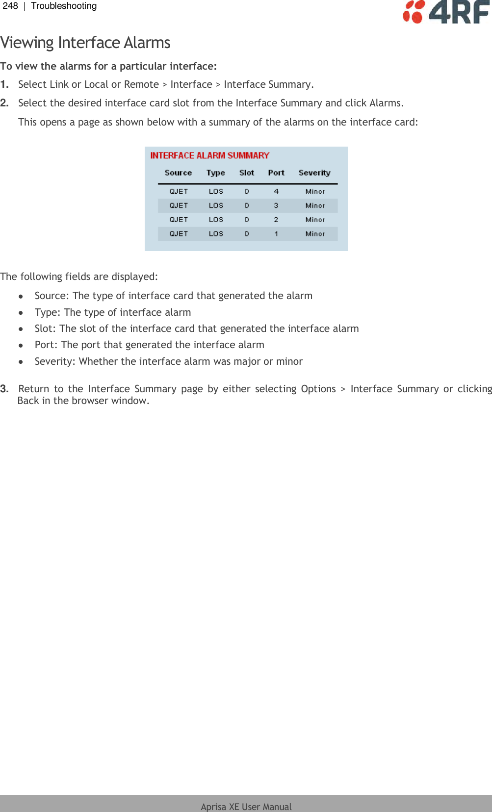
UserManual.wiki
>
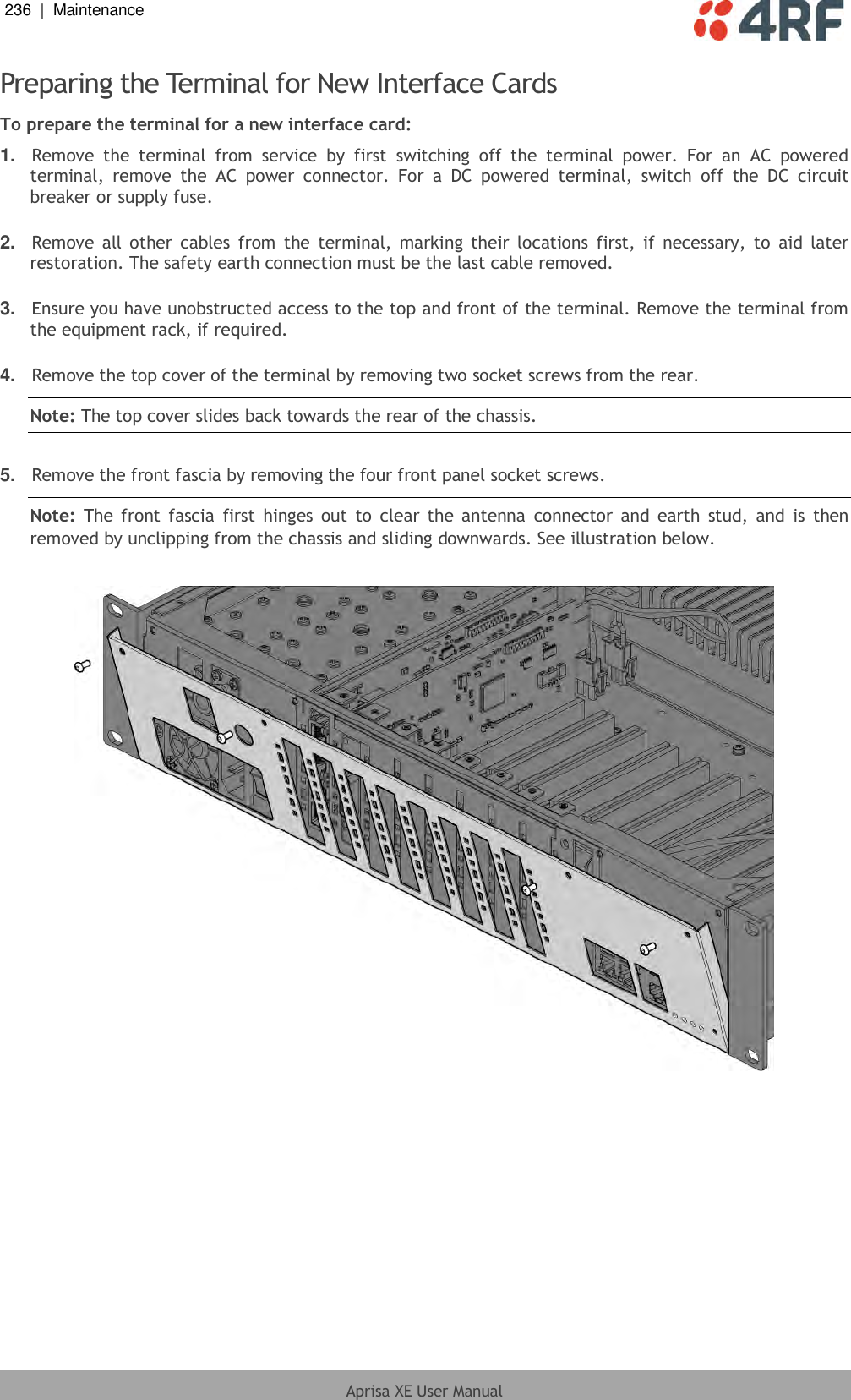
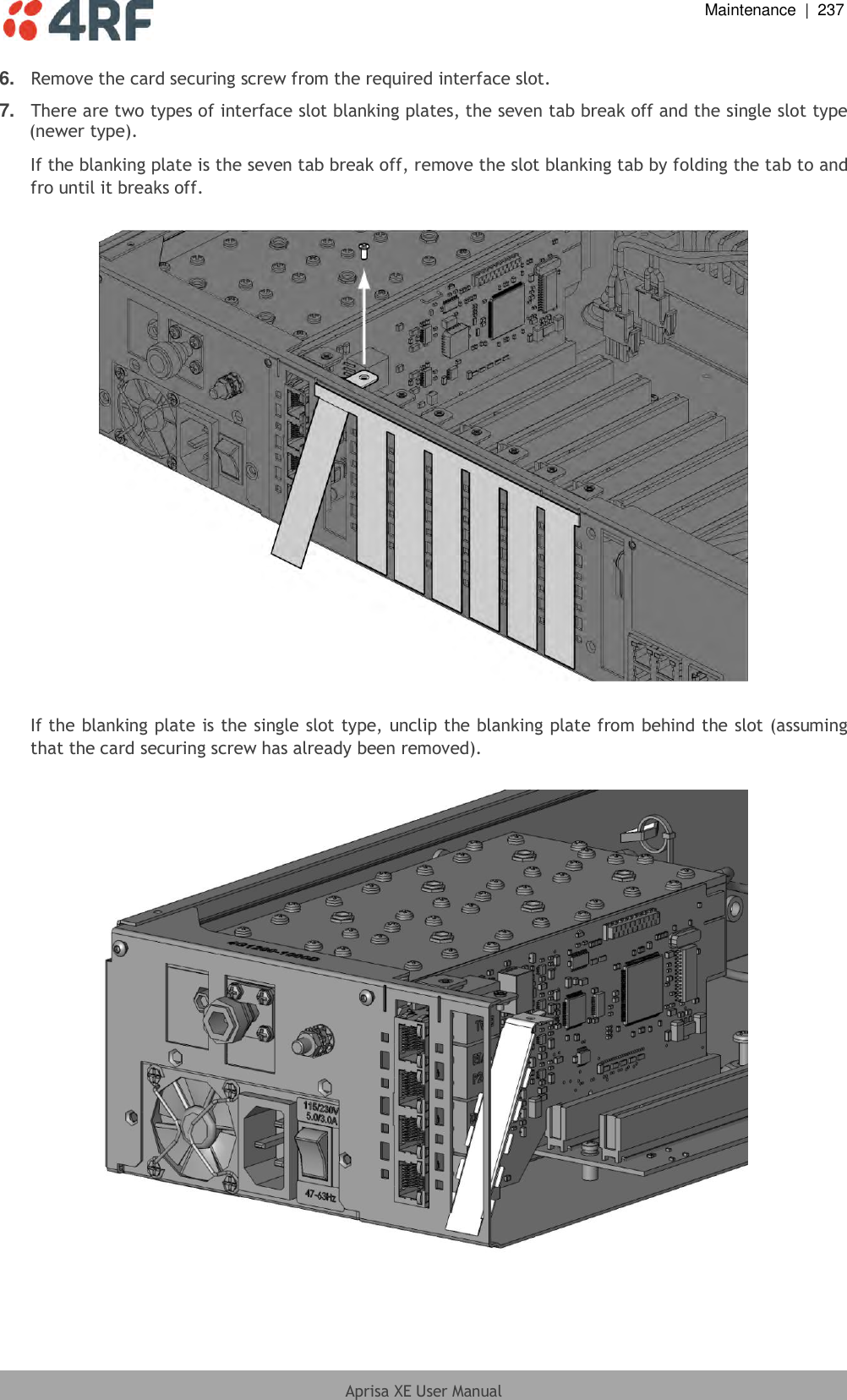
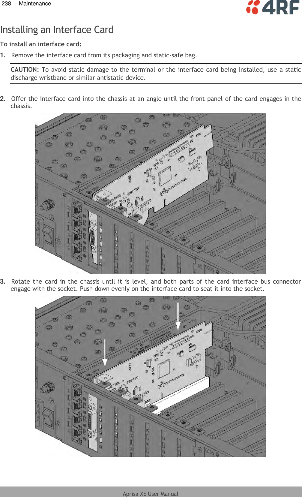
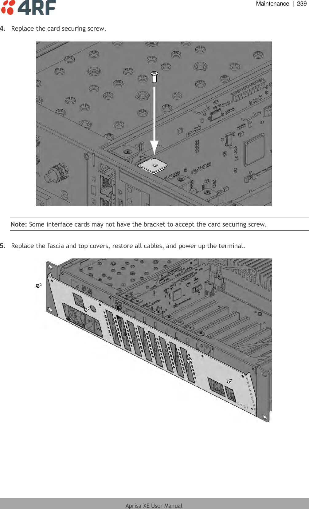
4RF
>
XE20001300 User Manual
User Manual Revised
Navigation menu
Upload a User Manual
Namespaces
Wiki Guide
HTML
PDF
Info
Views
User Manual
Discussion / Help
Navigation
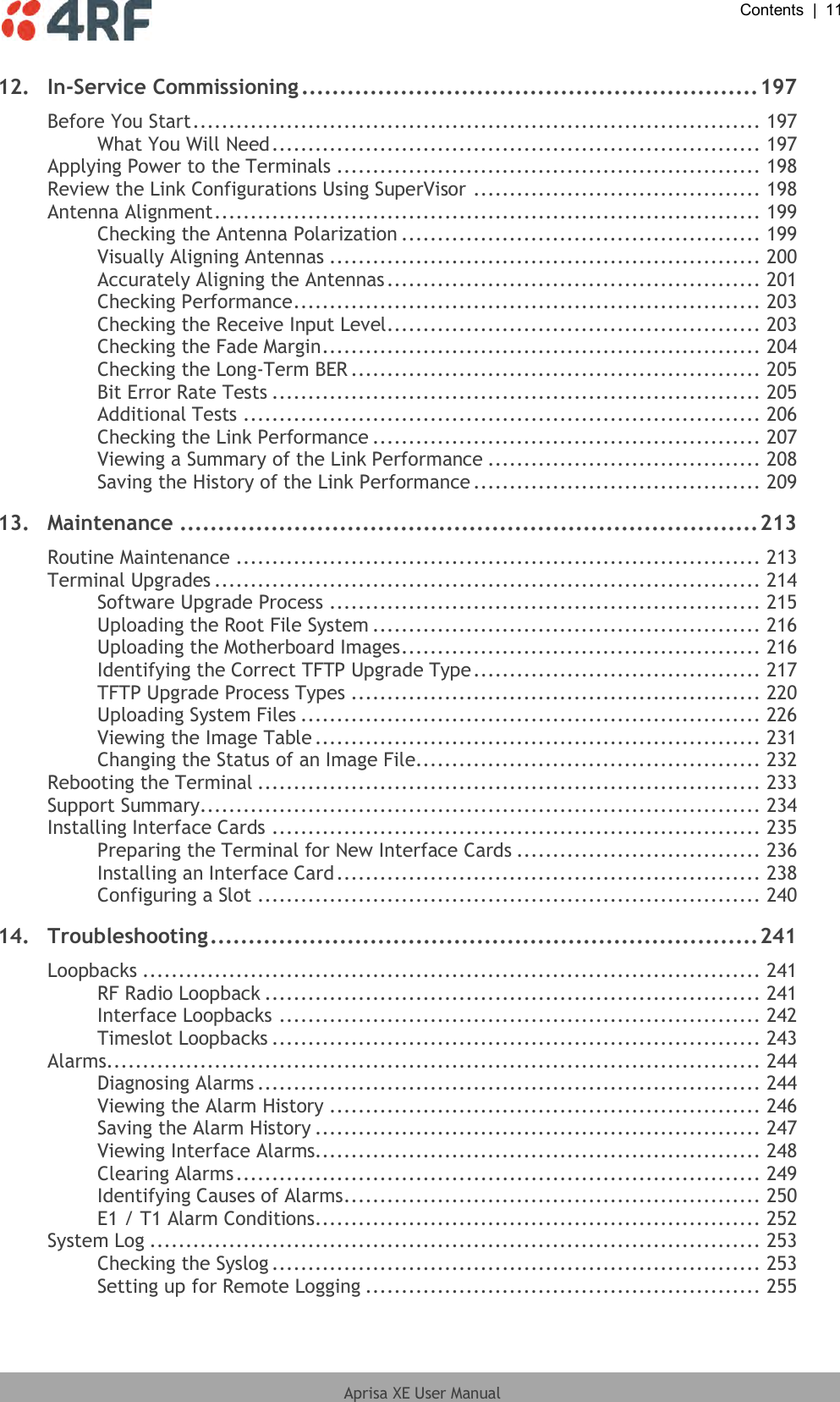

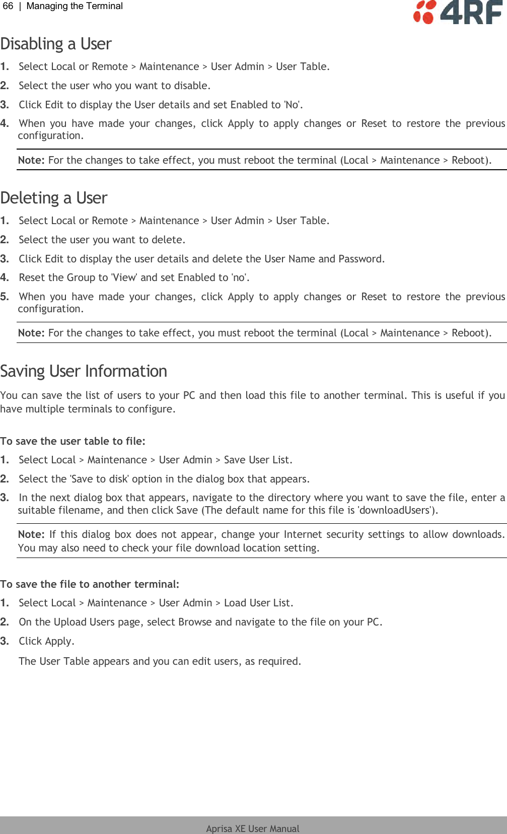
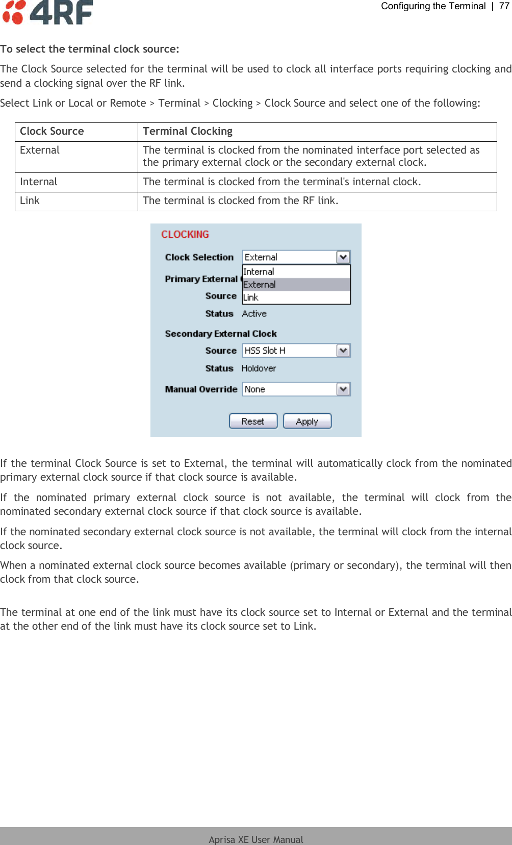
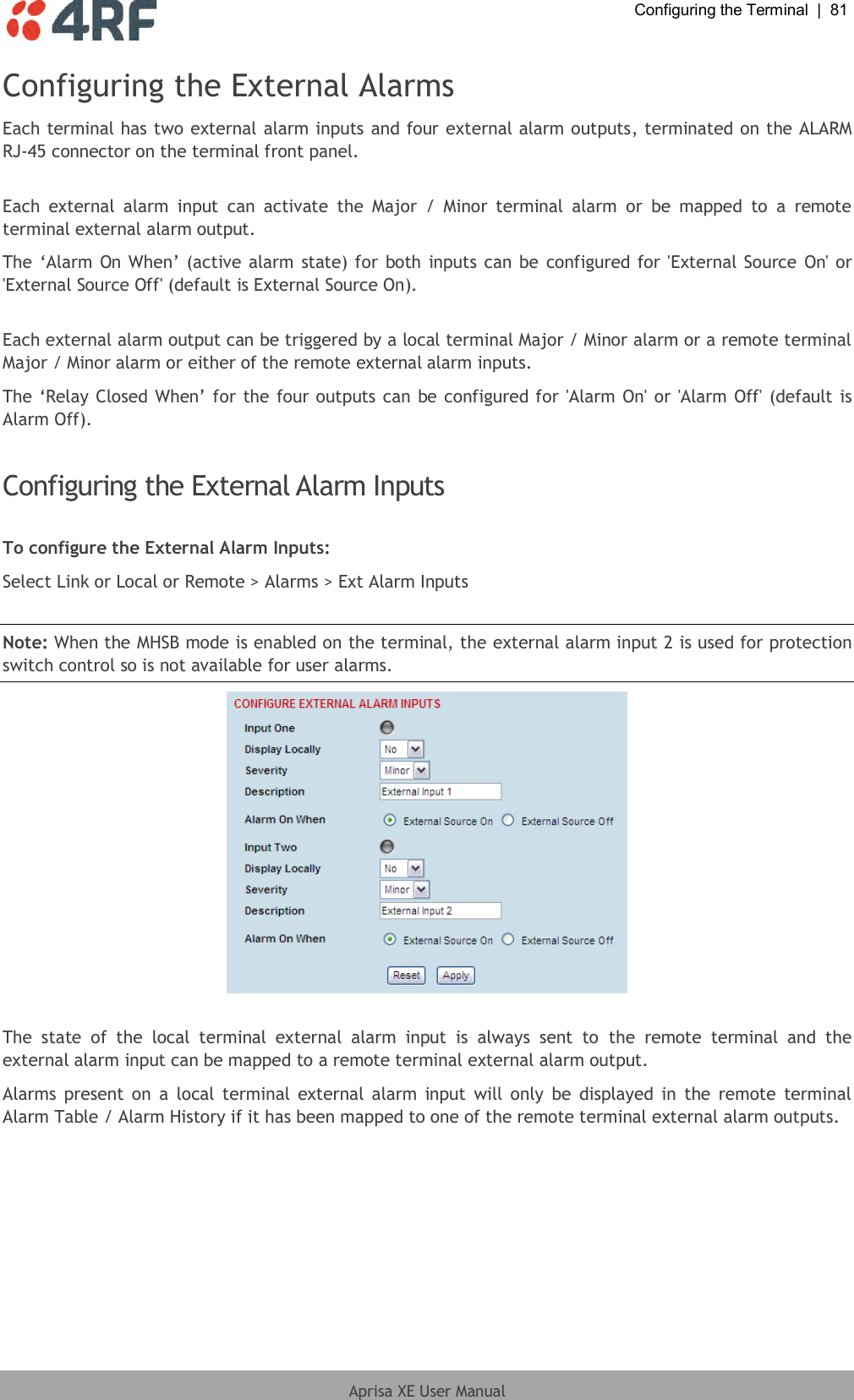
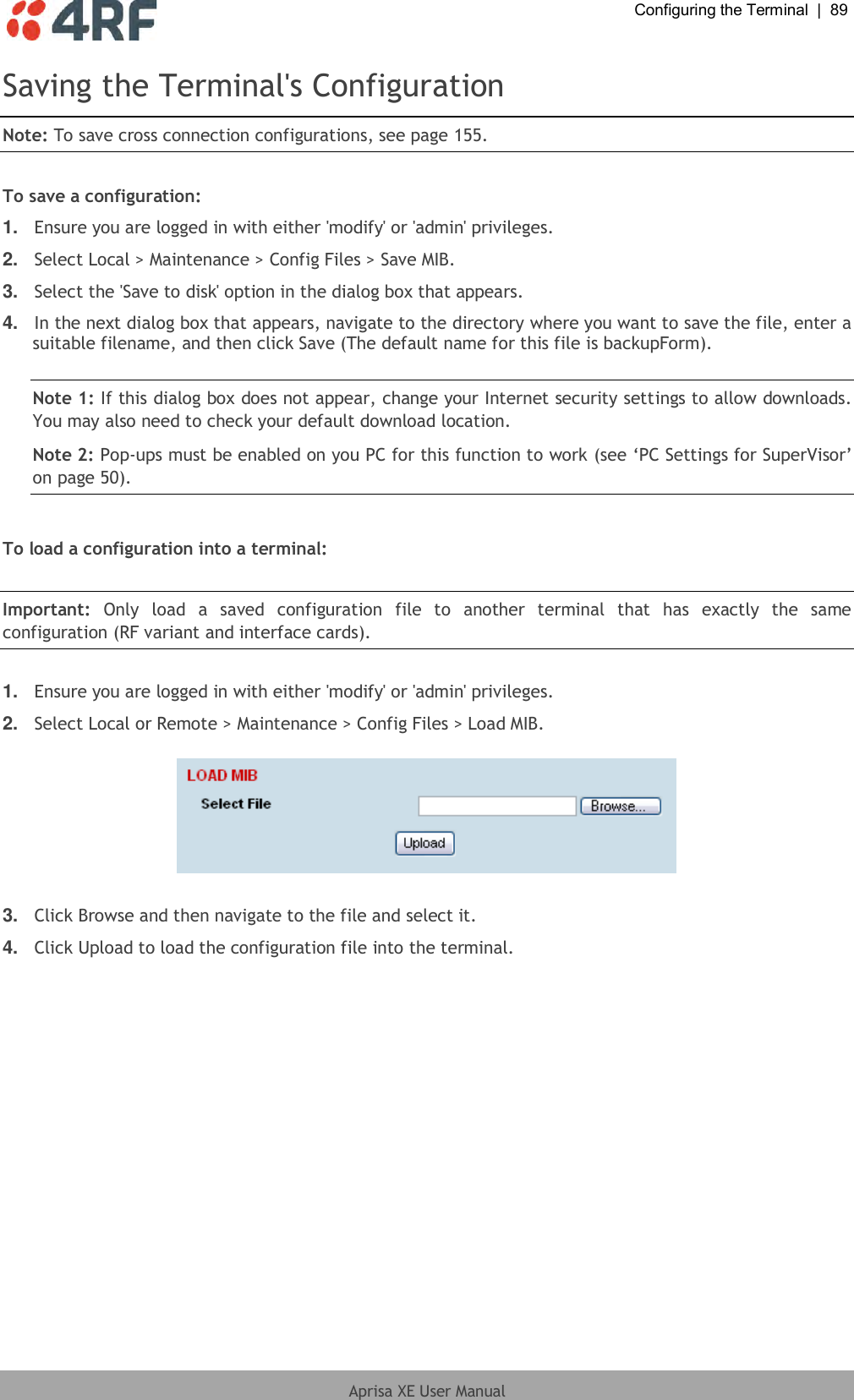

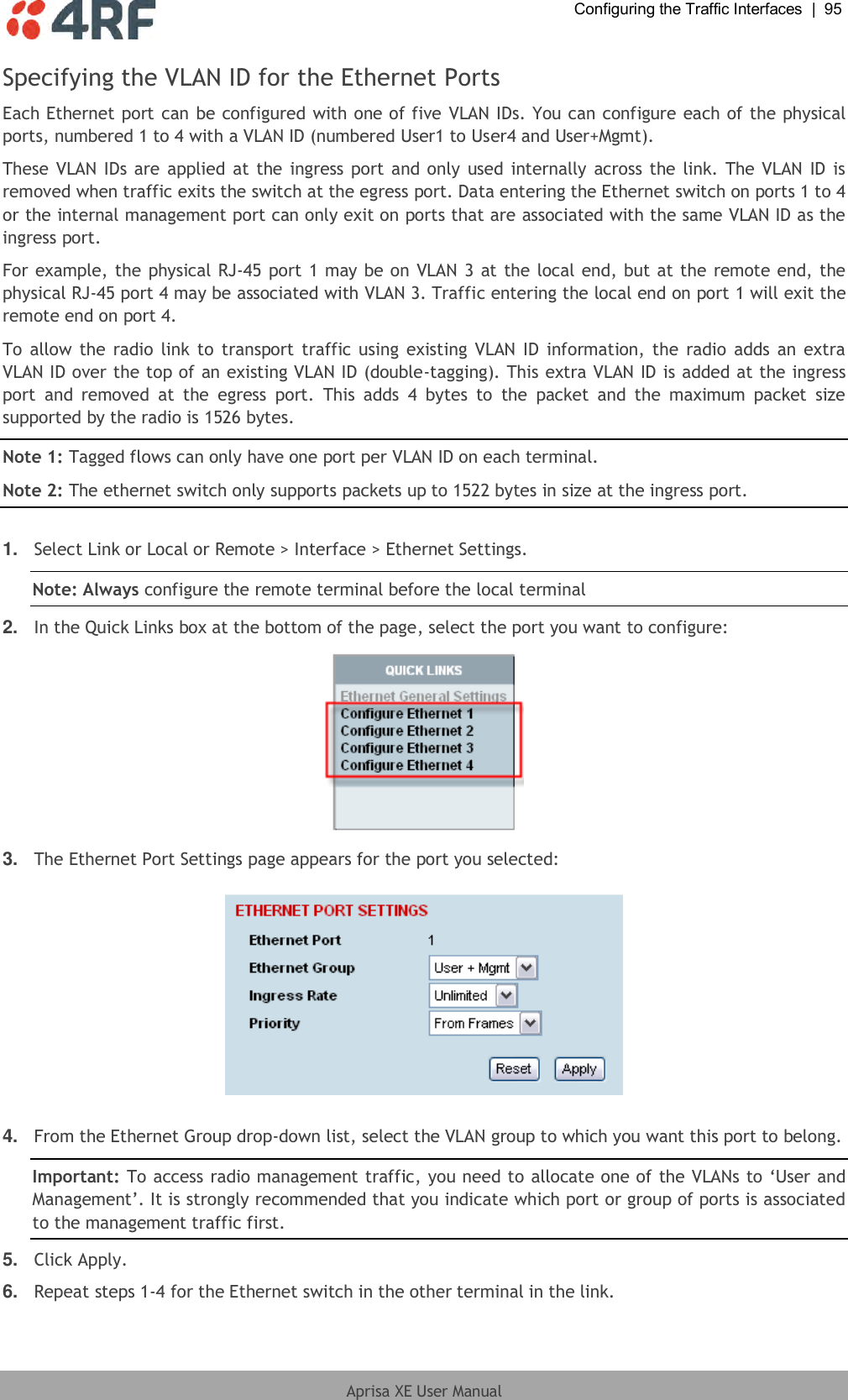
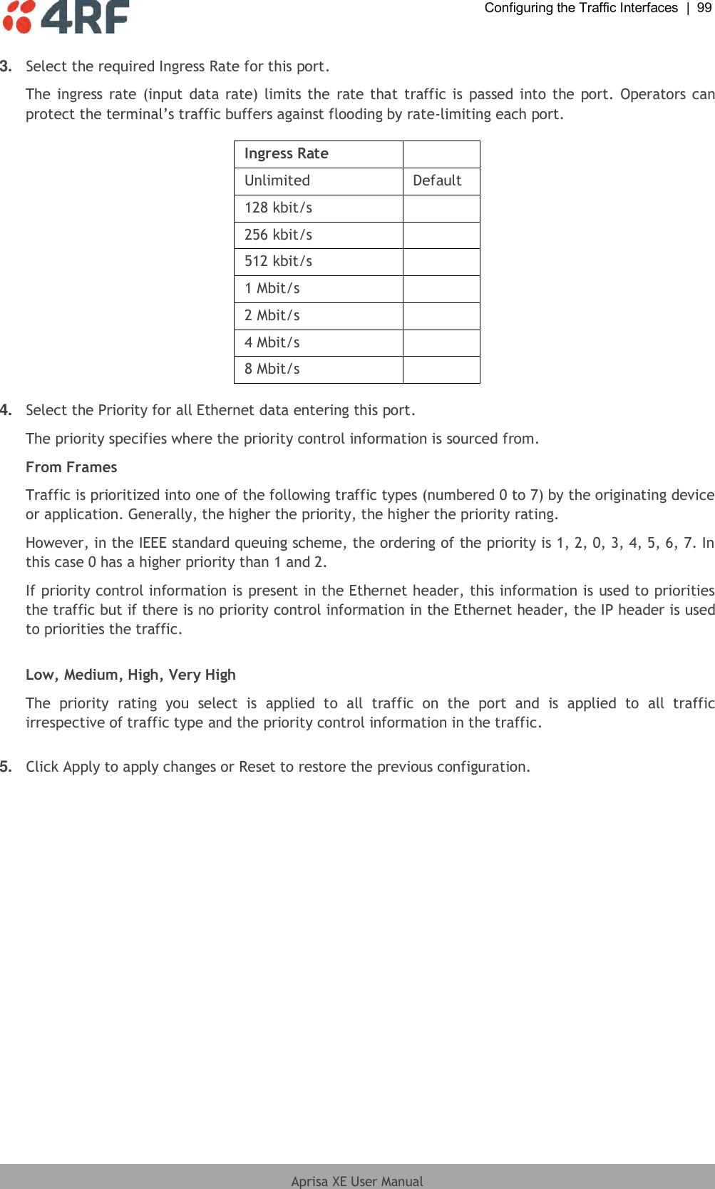
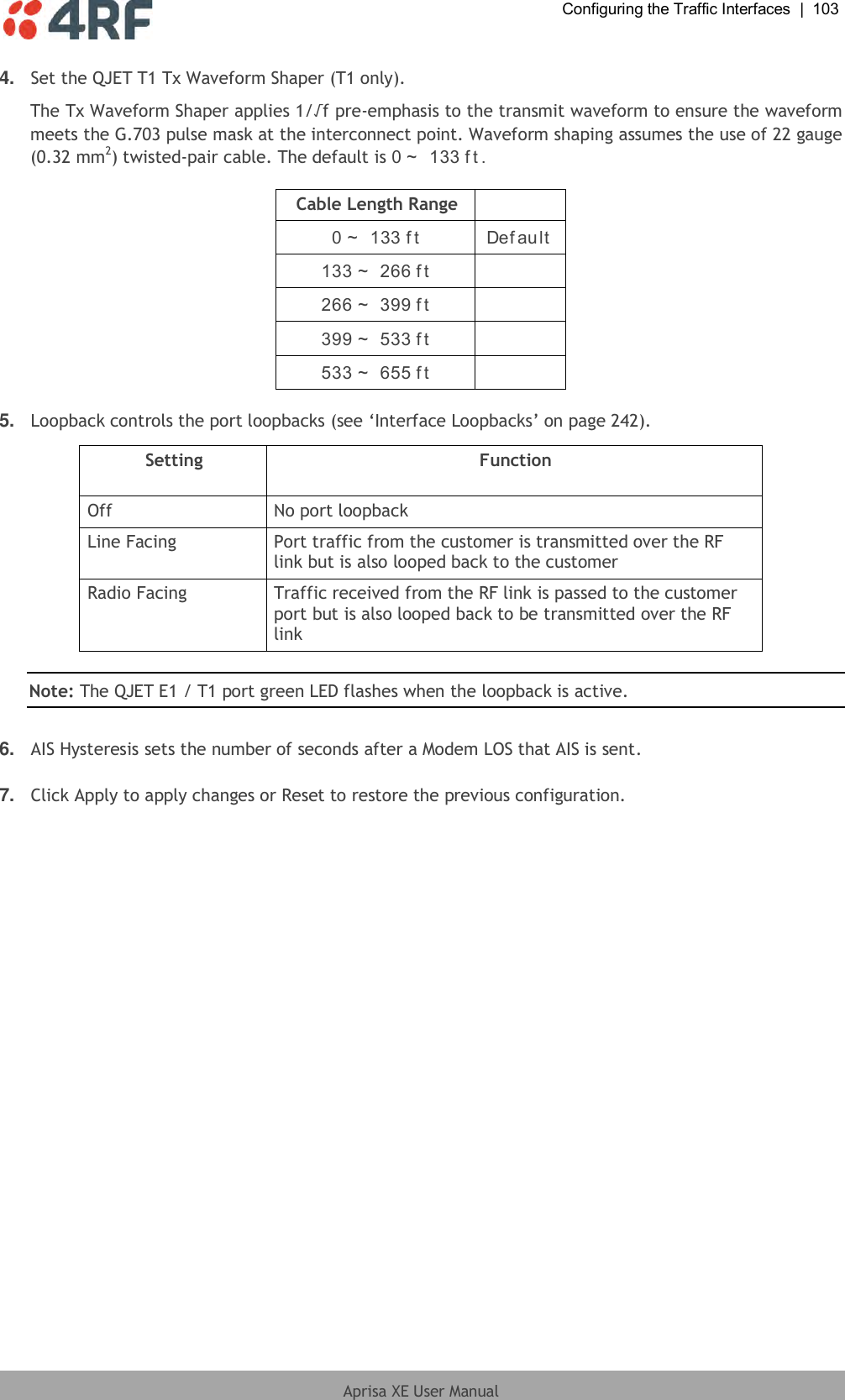
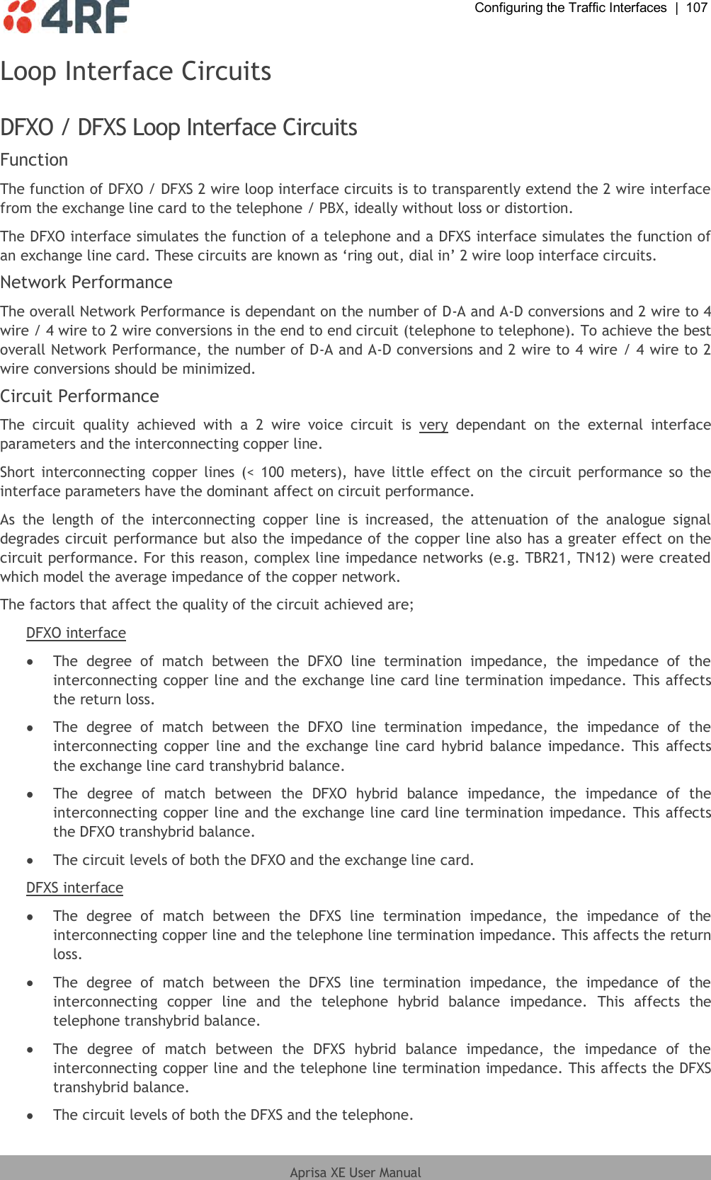
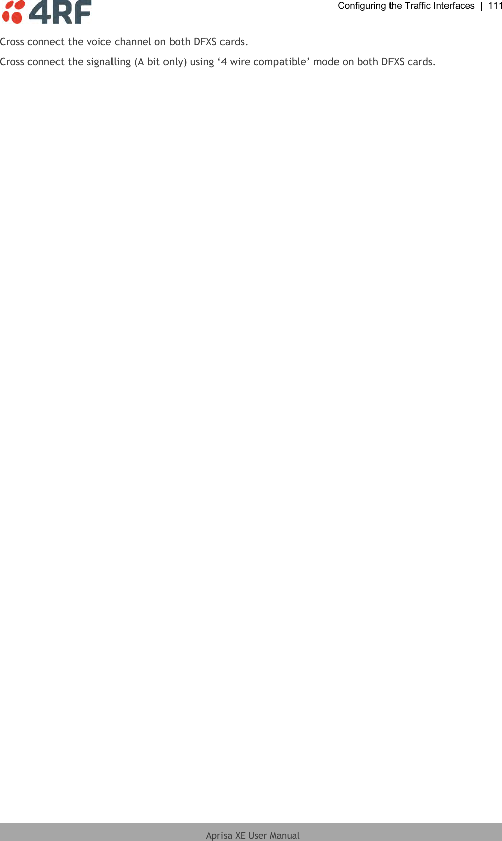
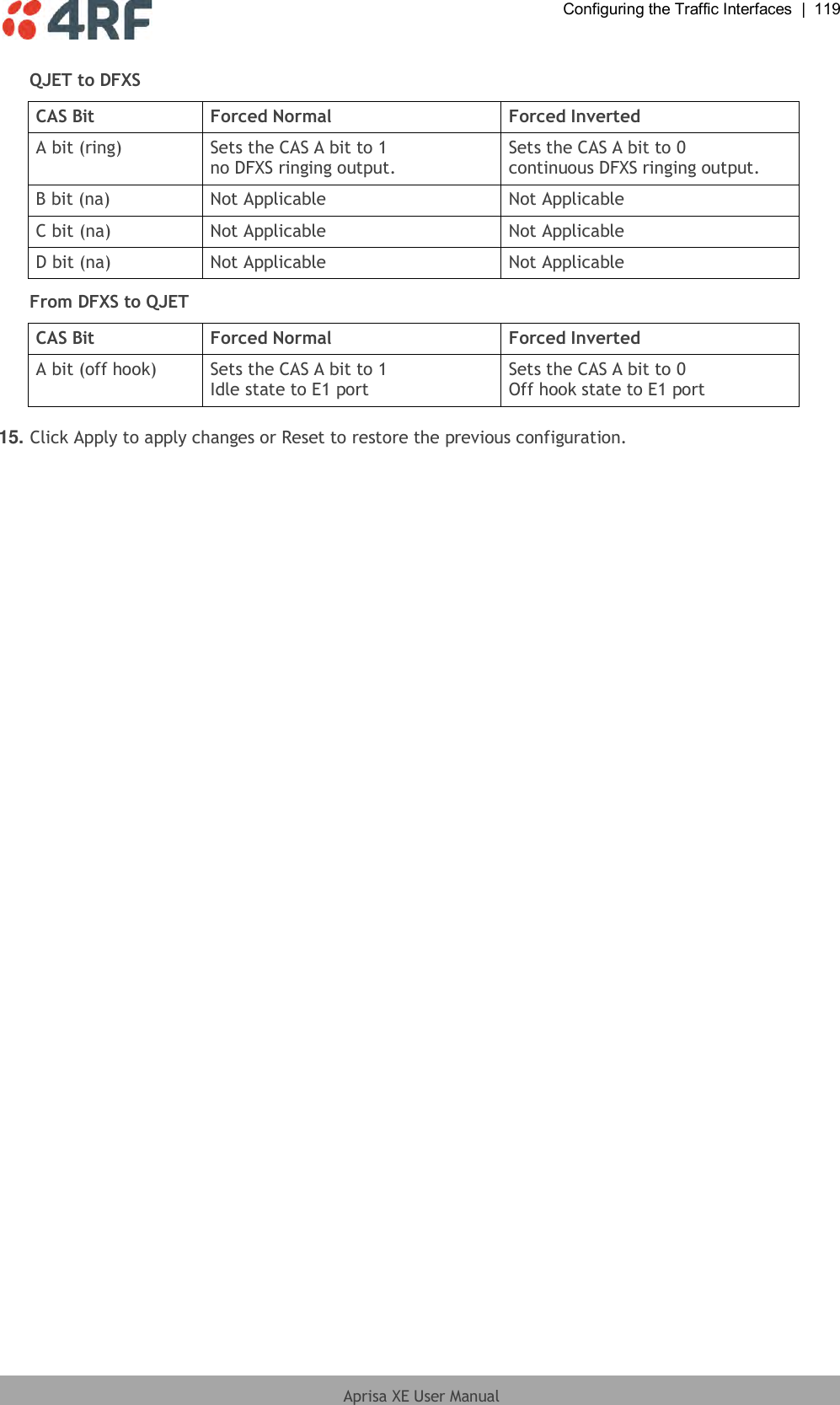
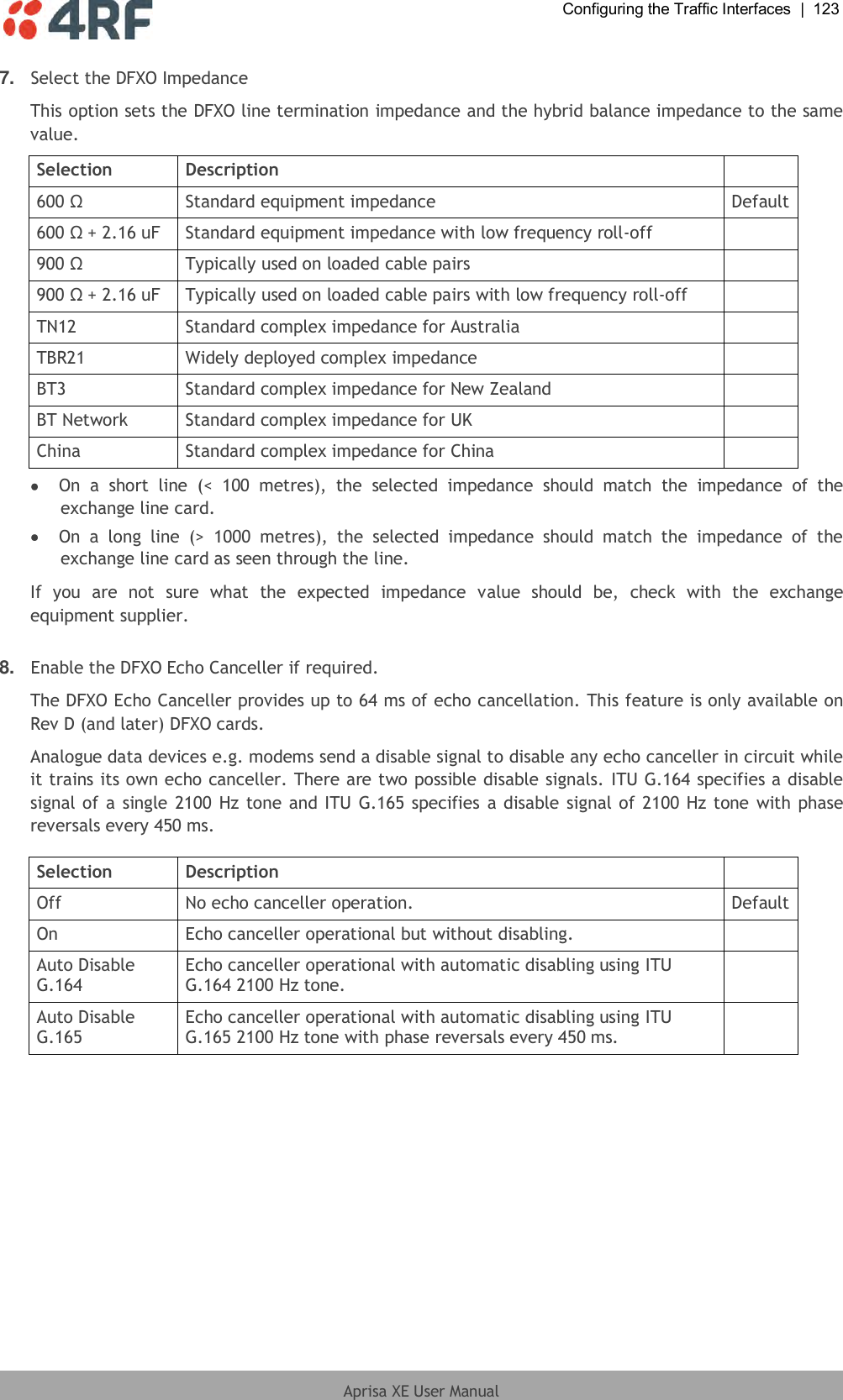
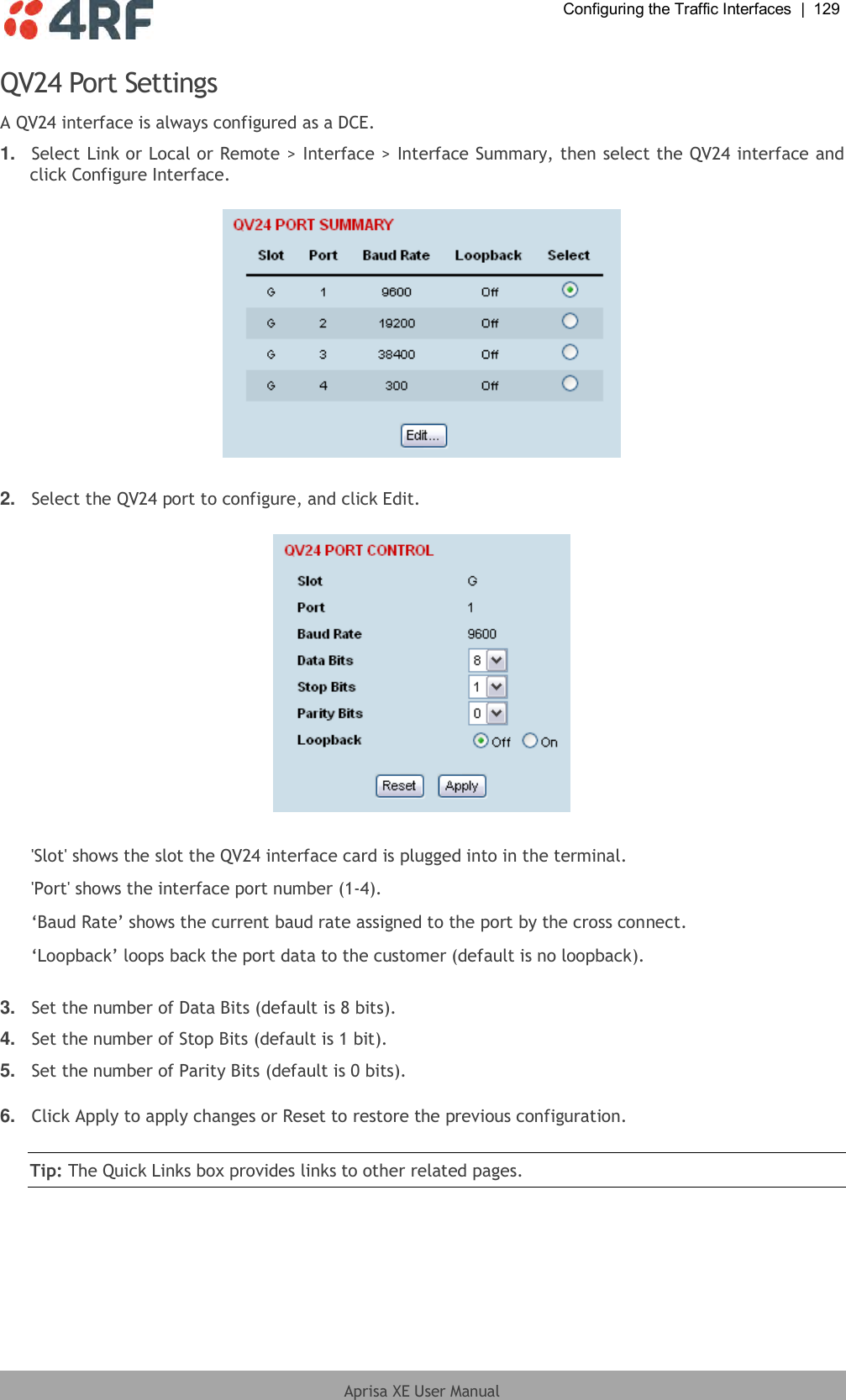
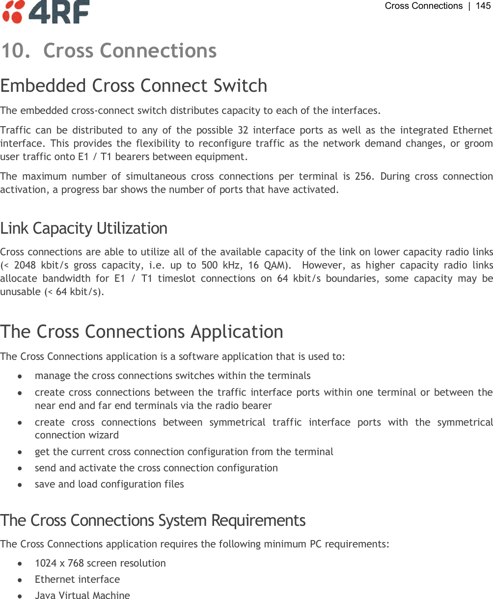
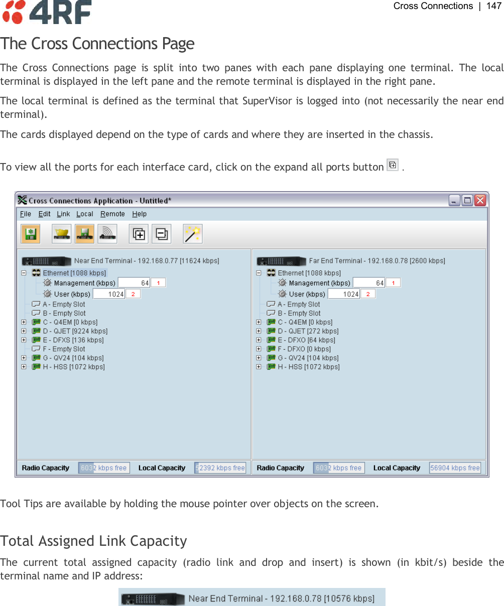

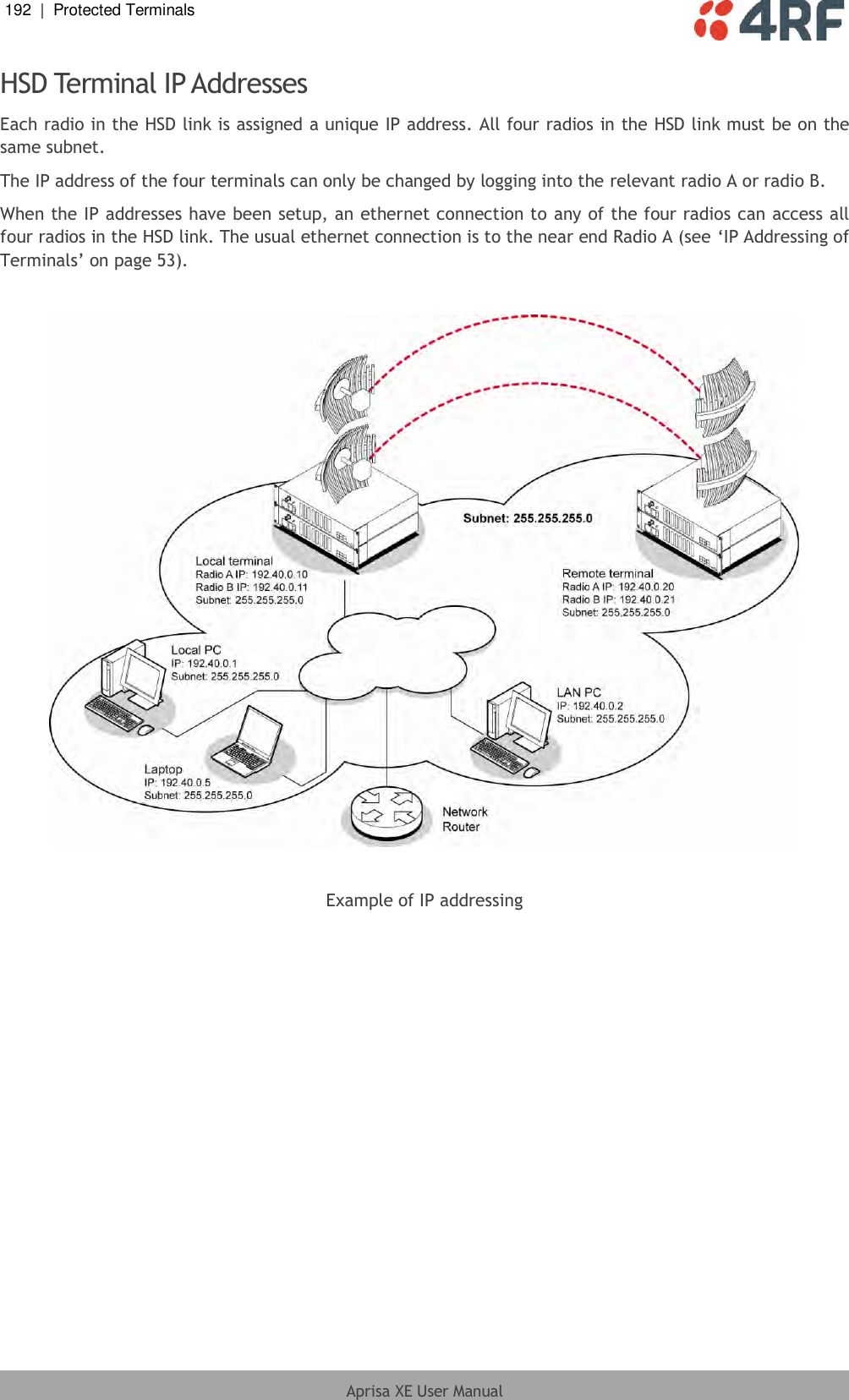
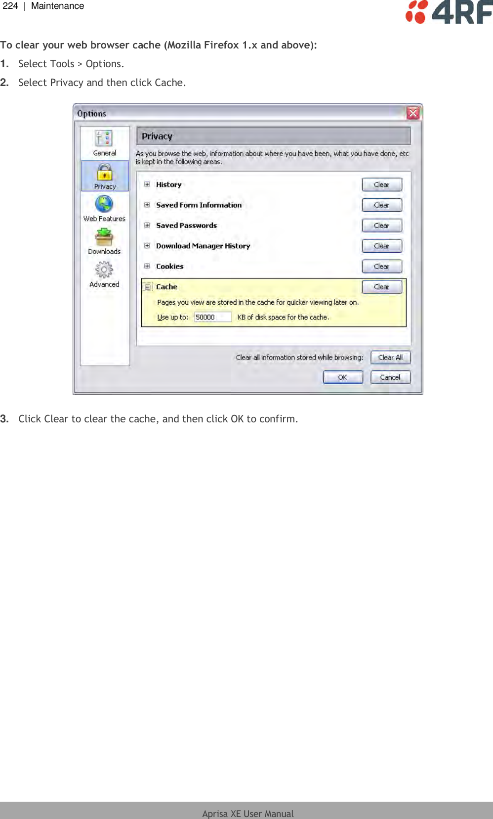
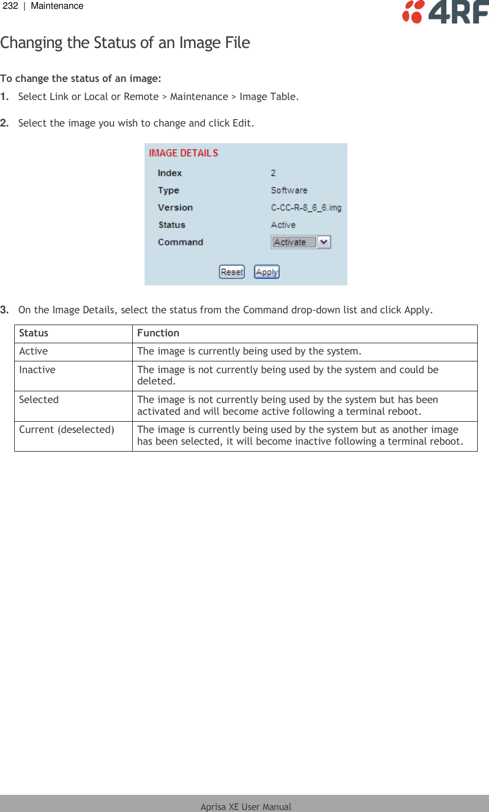
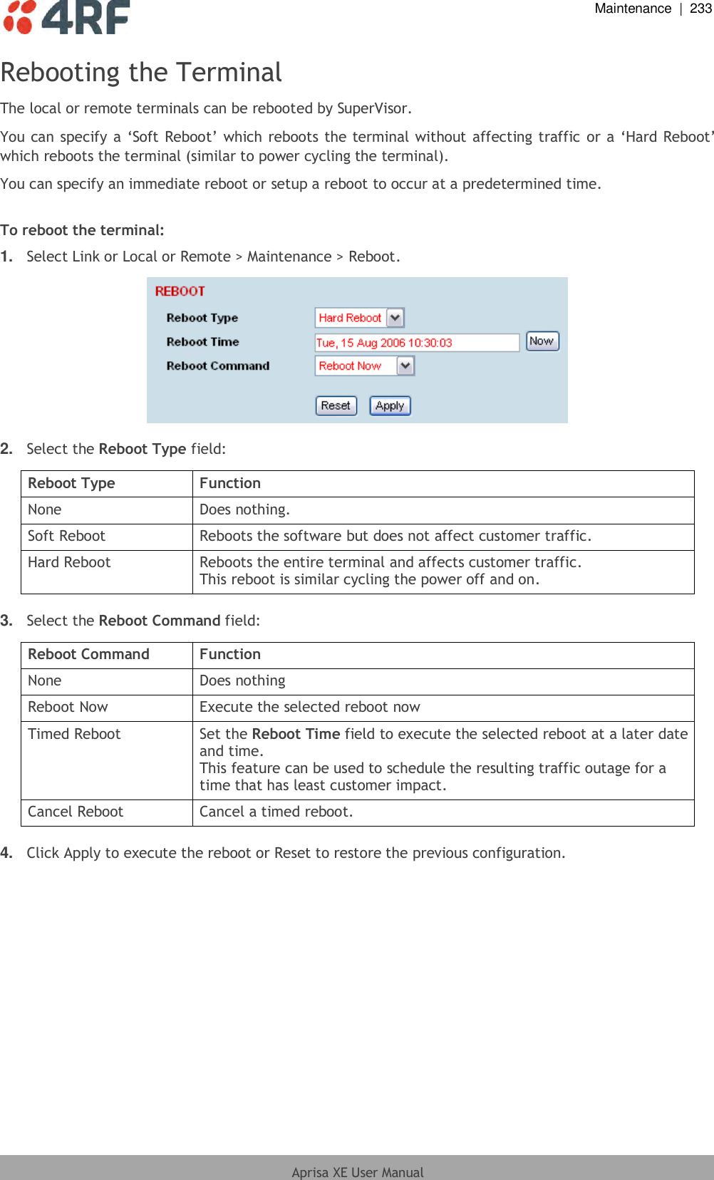
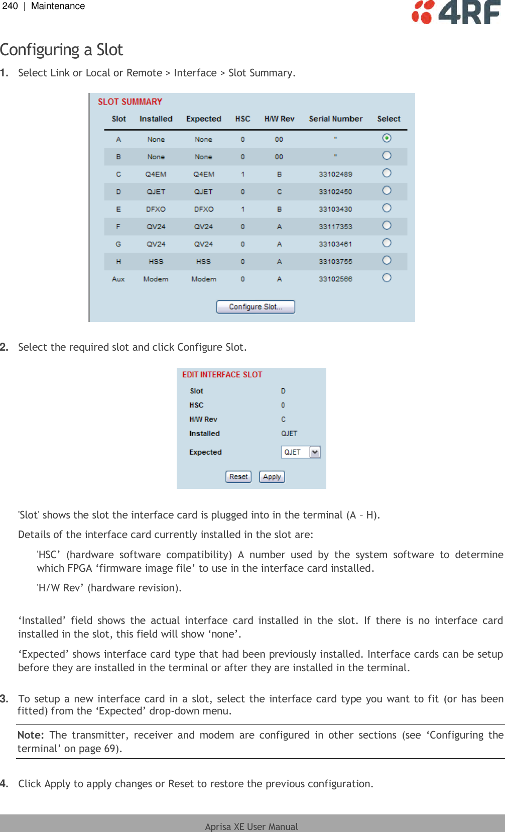
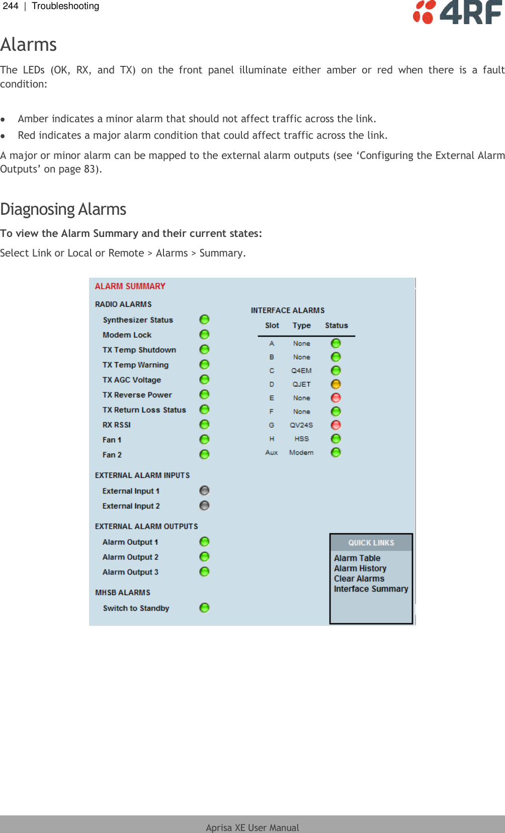
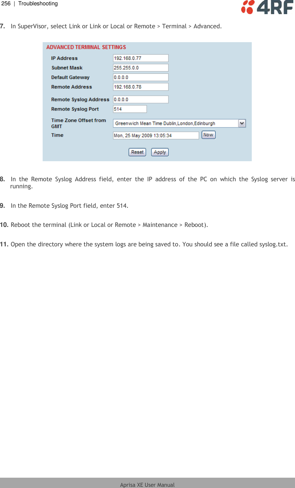
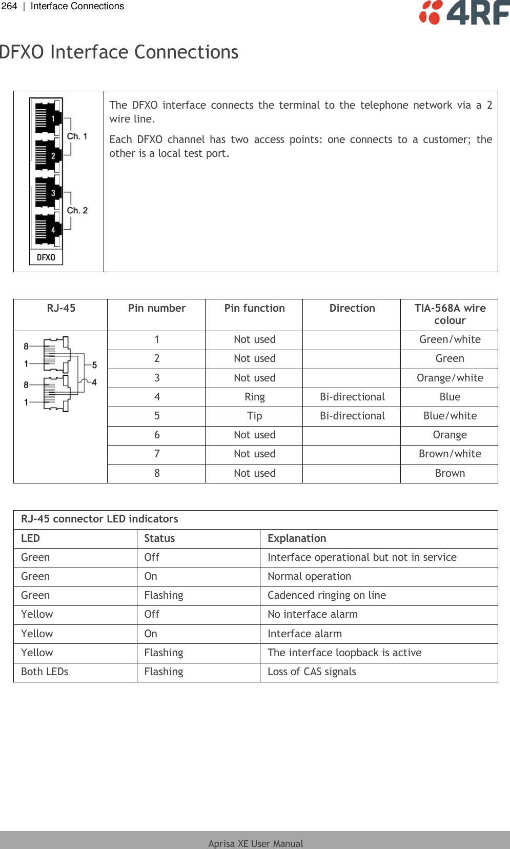
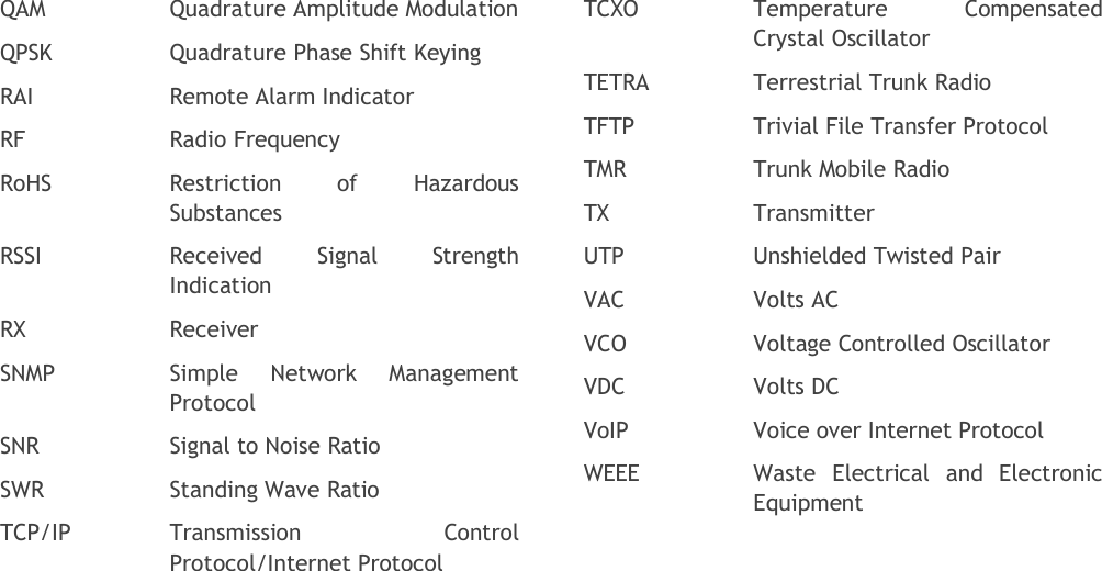
![222 | Maintenance Aprisa XE User Manual Step 2: Log into the Local terminal Use SuperVisor to log into the Near end terminal (now the Local terminal) (see ‘IP Addressing of Terminals’ on page 53) with either 'modify' or 'admin' privileges. Step 3: Run the TFTP upgrade process on the Remote terminal 1. Select Remote > Maintenance > Upload > TFTP Upgrade. 2. Enter the IP address of the TFTP server. 3. Enter the version number of the software that you are upgrading to as a three digit number separated by underscores, for example, 8_6_77_E0 for ETSI variants. 4. Click Apply and check the TFTP server for download activity. The Upgrade Result changes from 'Executing' to either 'Succeeded' or 'Failed'. Note: This may take several minutes when upgrading the remote terminal. If the upgrade has failed: The TFTP server IP address may be set incorrectly The 'Current Directory' on the TFTP server was not pointing to the location of the upload config file e.g. 'Rel_8_6_77_E0.cfg' . There may not be enough free space in the image table to write the file. Inactive images can be deleted (and the terminal rebooted) to free up space for the new image (see ‘Changing the Status of an Image File’ on page 232). Step 4: Reboot the Remote terminal Reboot the remote terminal before proceeding with the next step of the upgrade process (see ‘Rebooting the Terminal’ on page 233). 1. Select Remote > Maintenance > Reboot and select [Hard Reboot] Communications to SuperVisor remote page will fail until the remote terminal reboot has completed.](https://usermanual.wiki/4RF/XE20001300/User-Guide-1961219-Page-225.png)
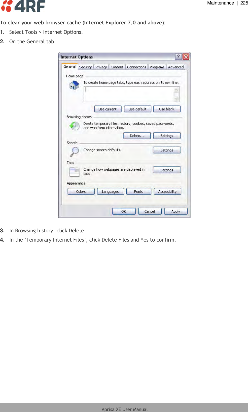
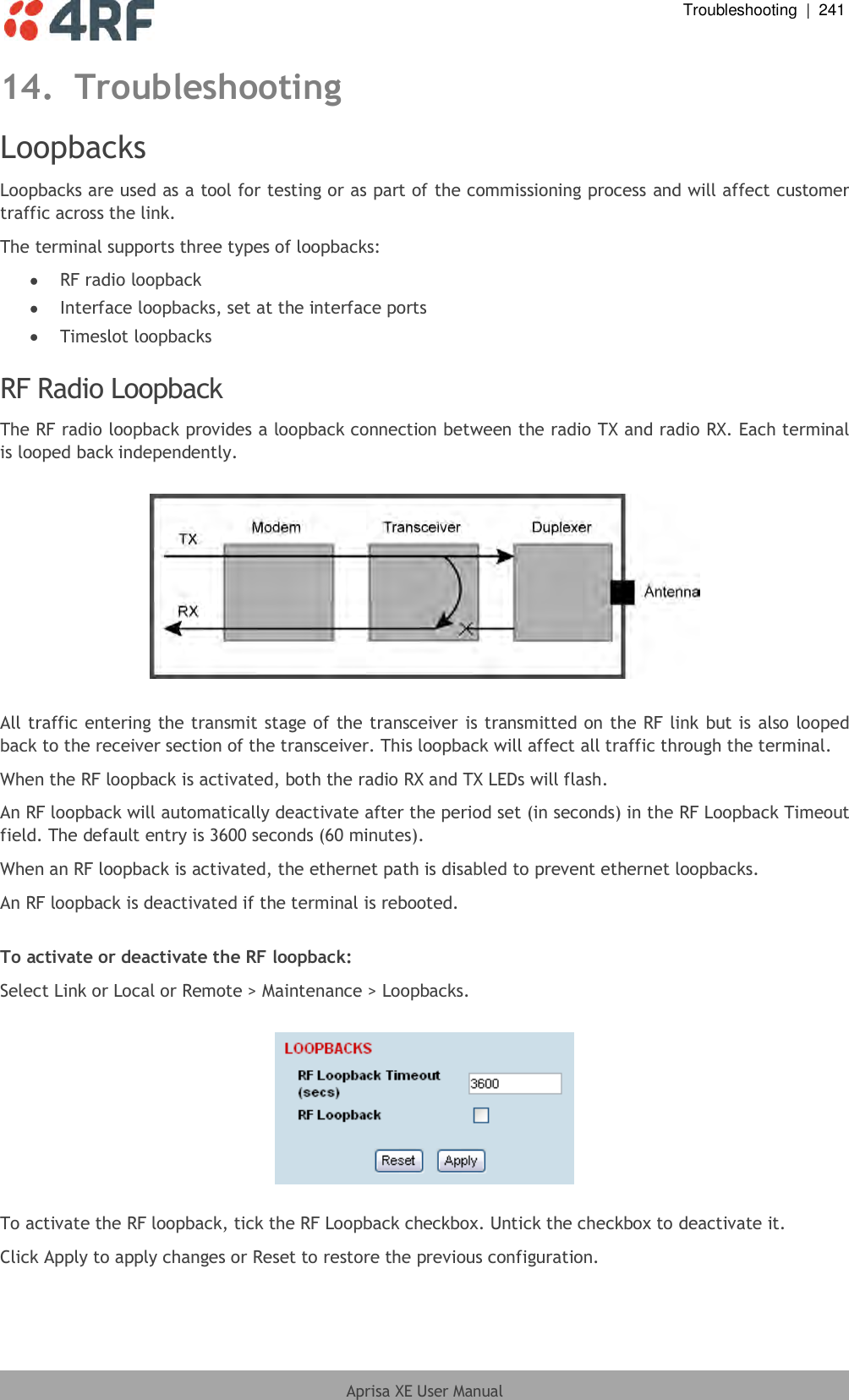
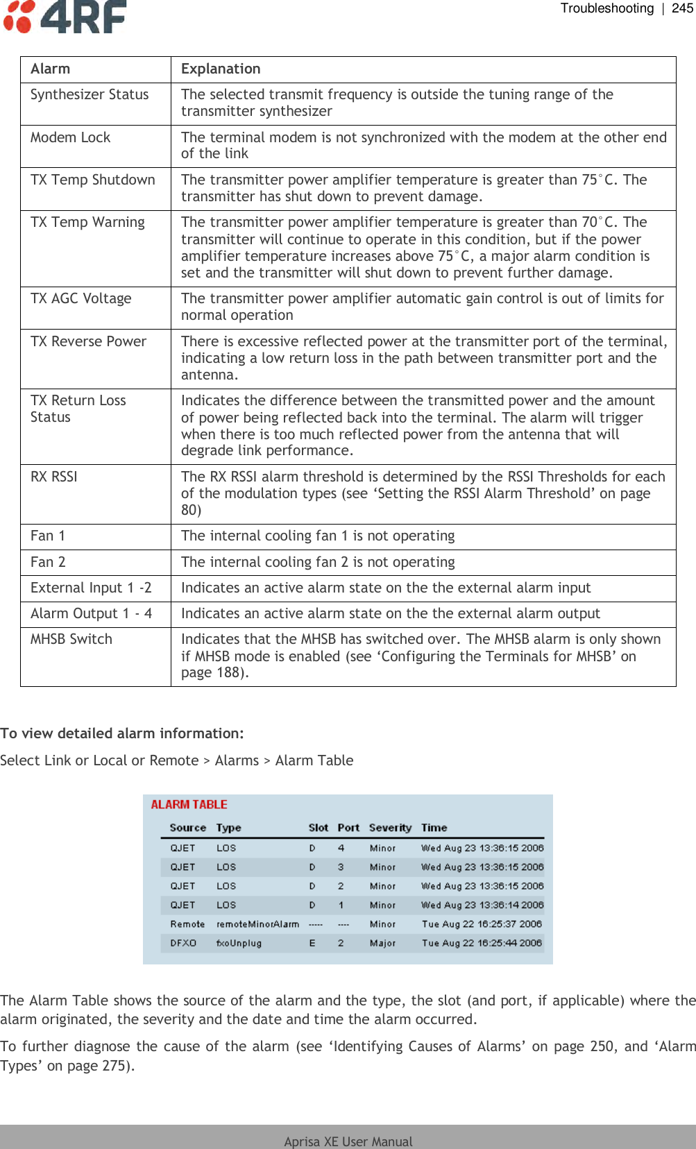
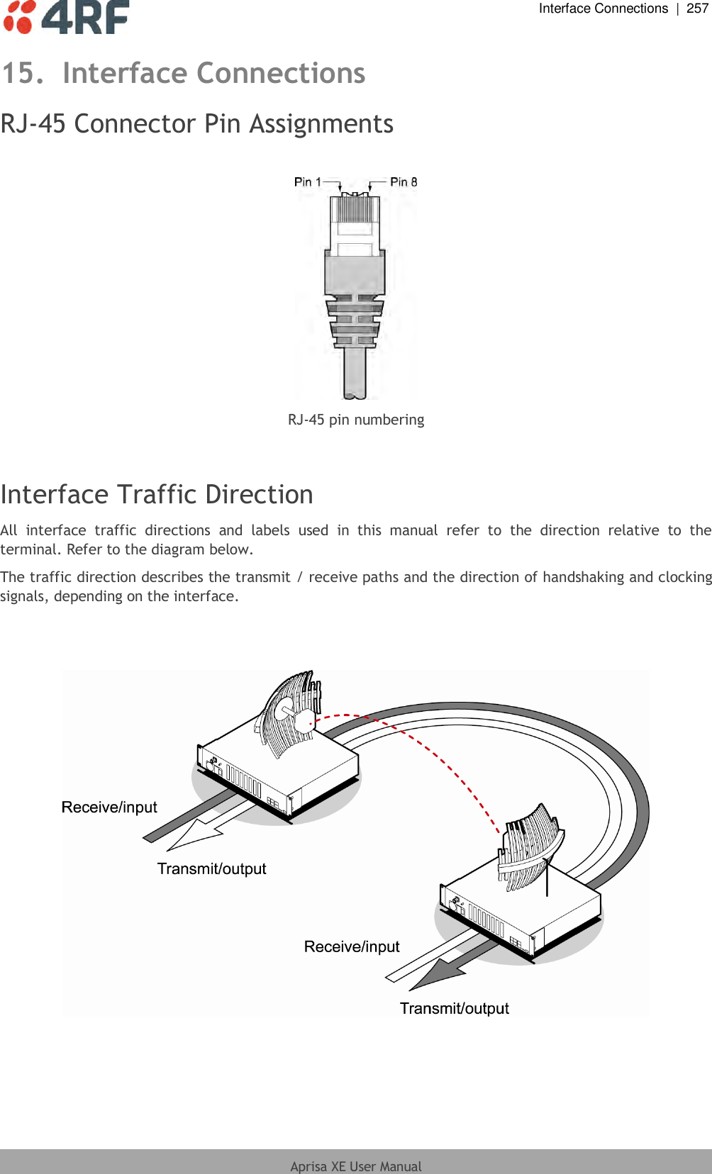
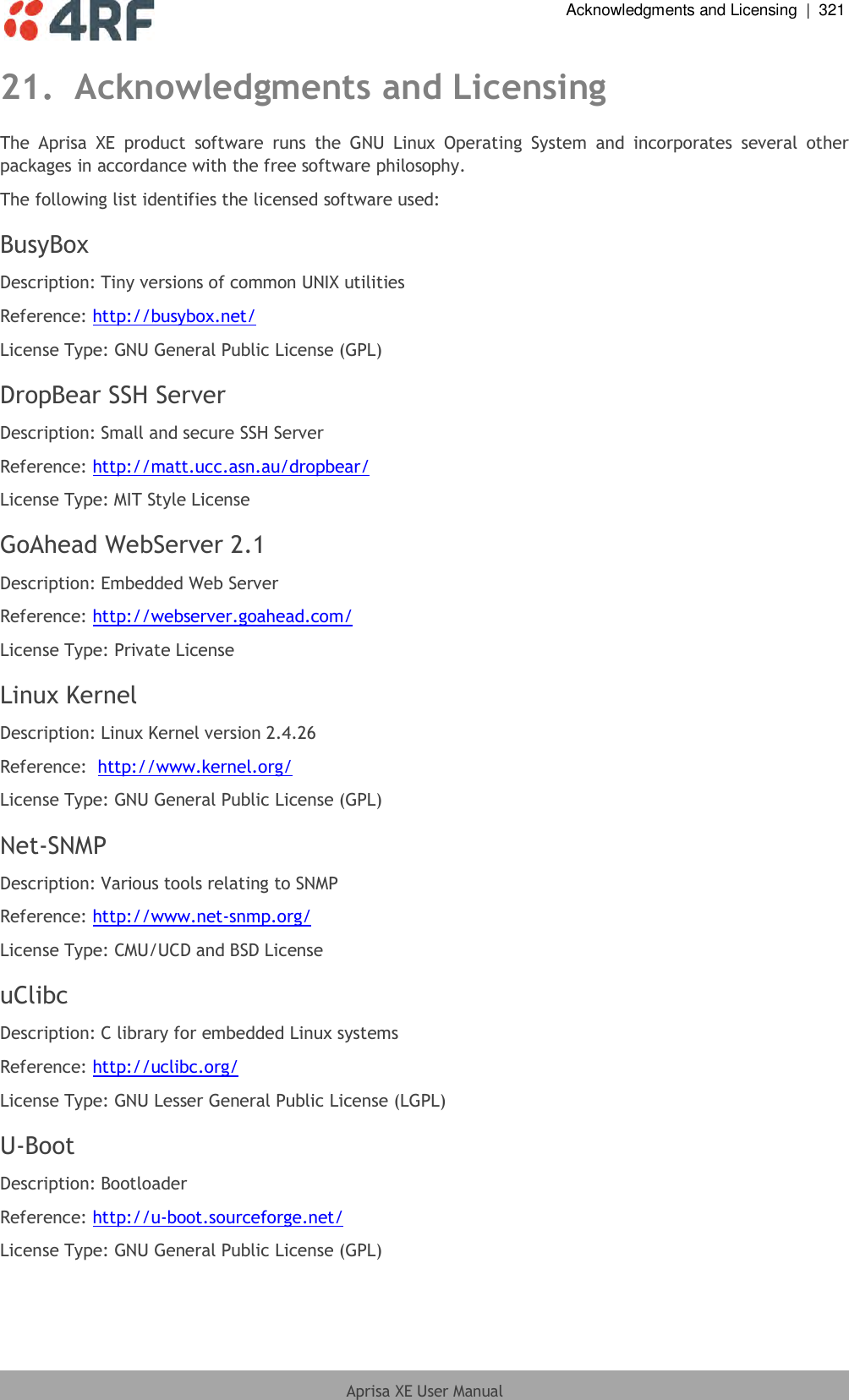
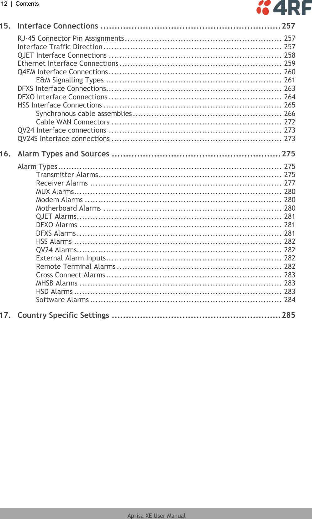
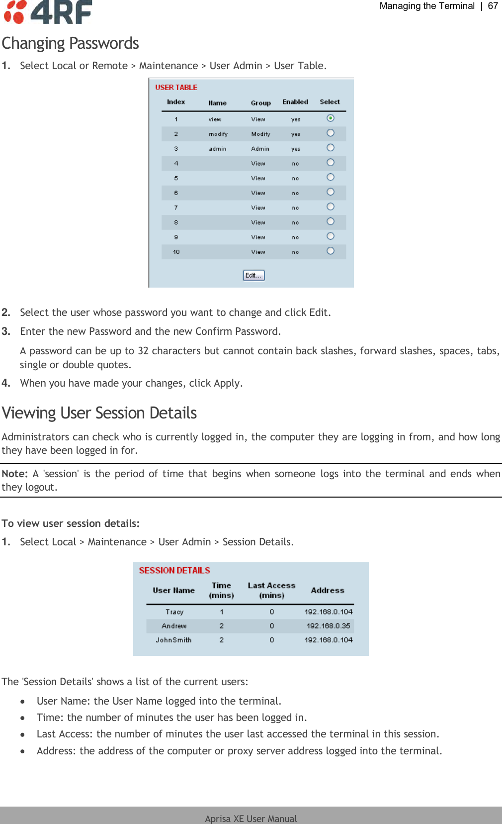
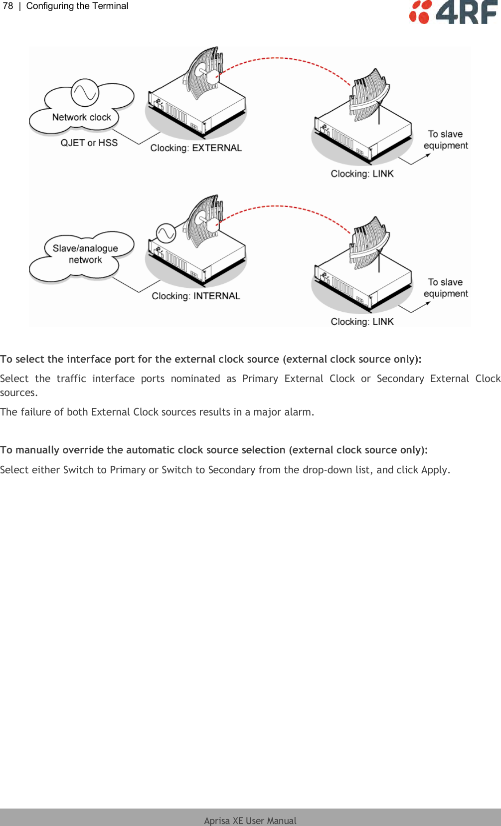
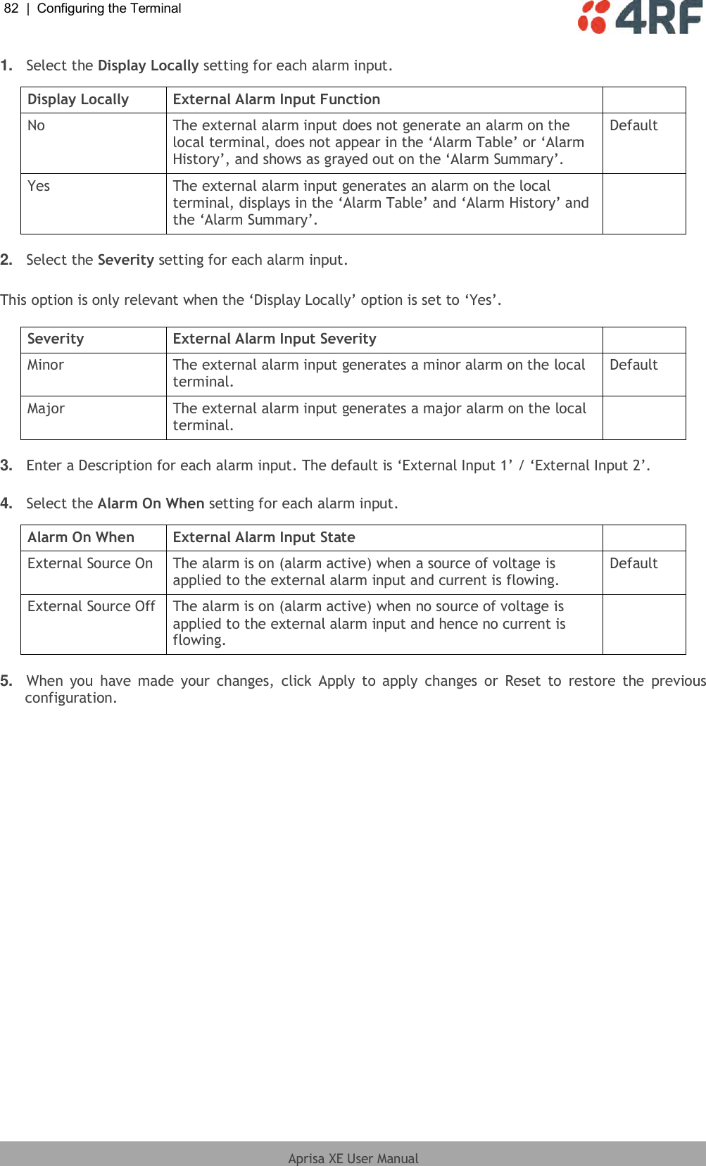
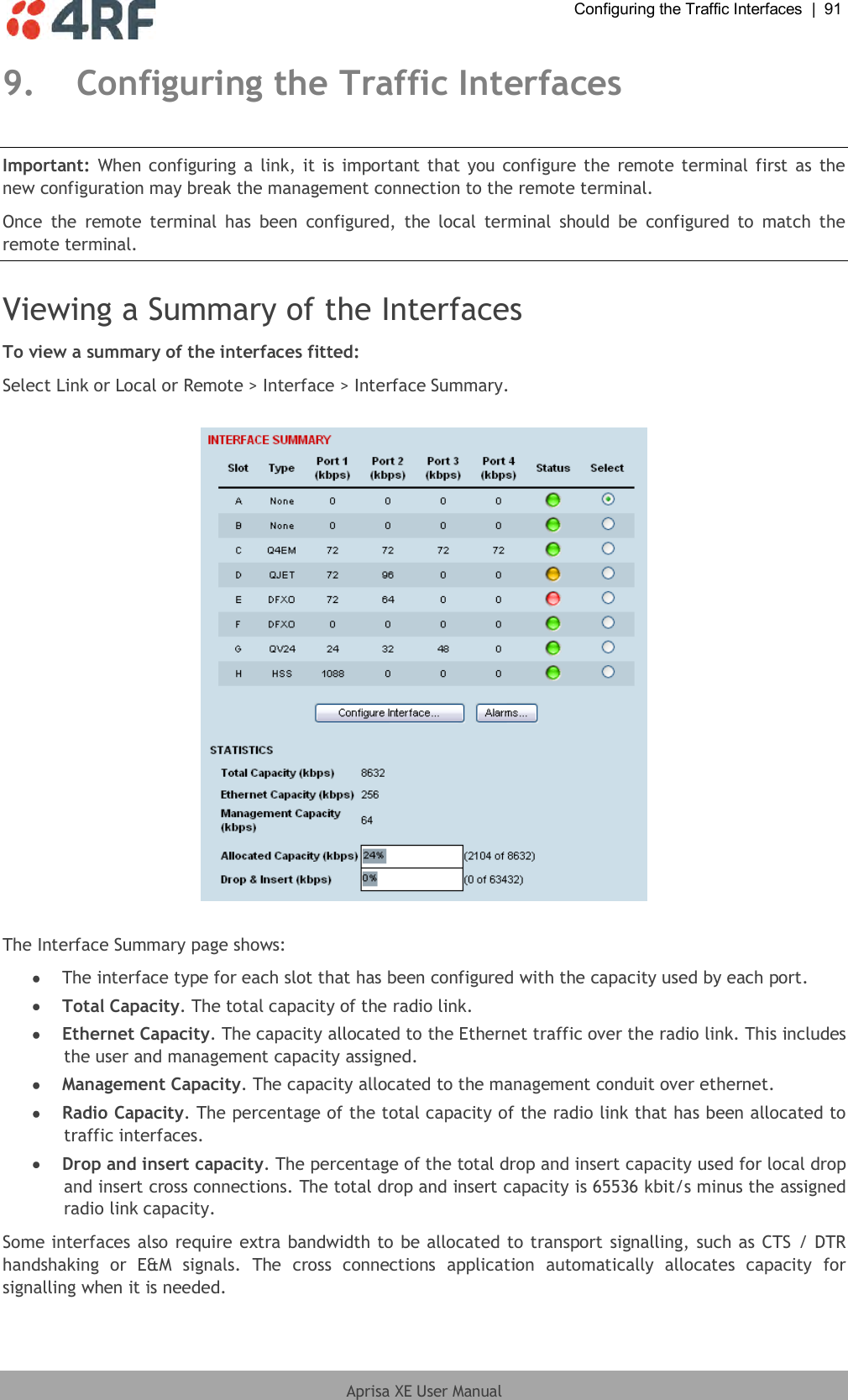
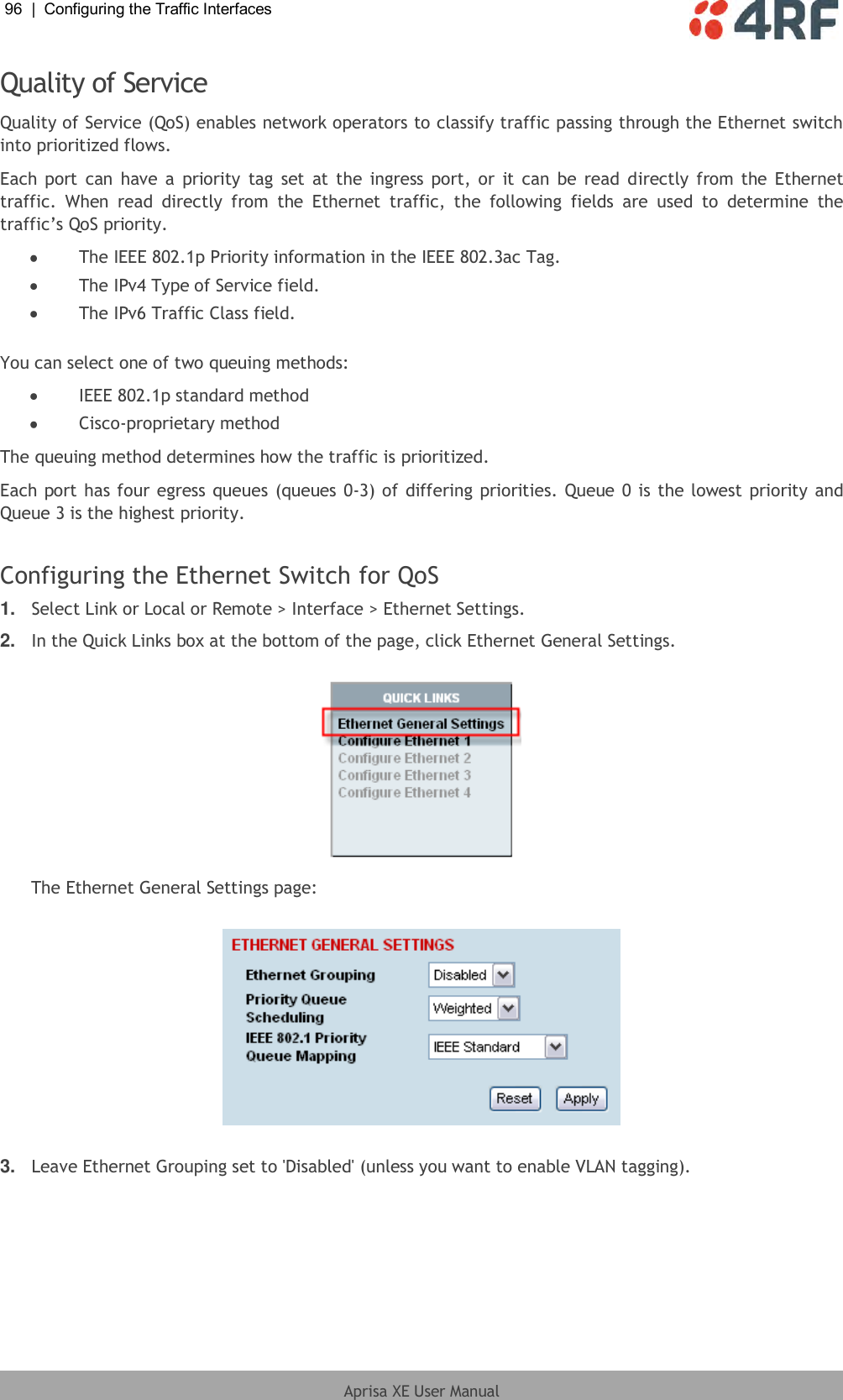
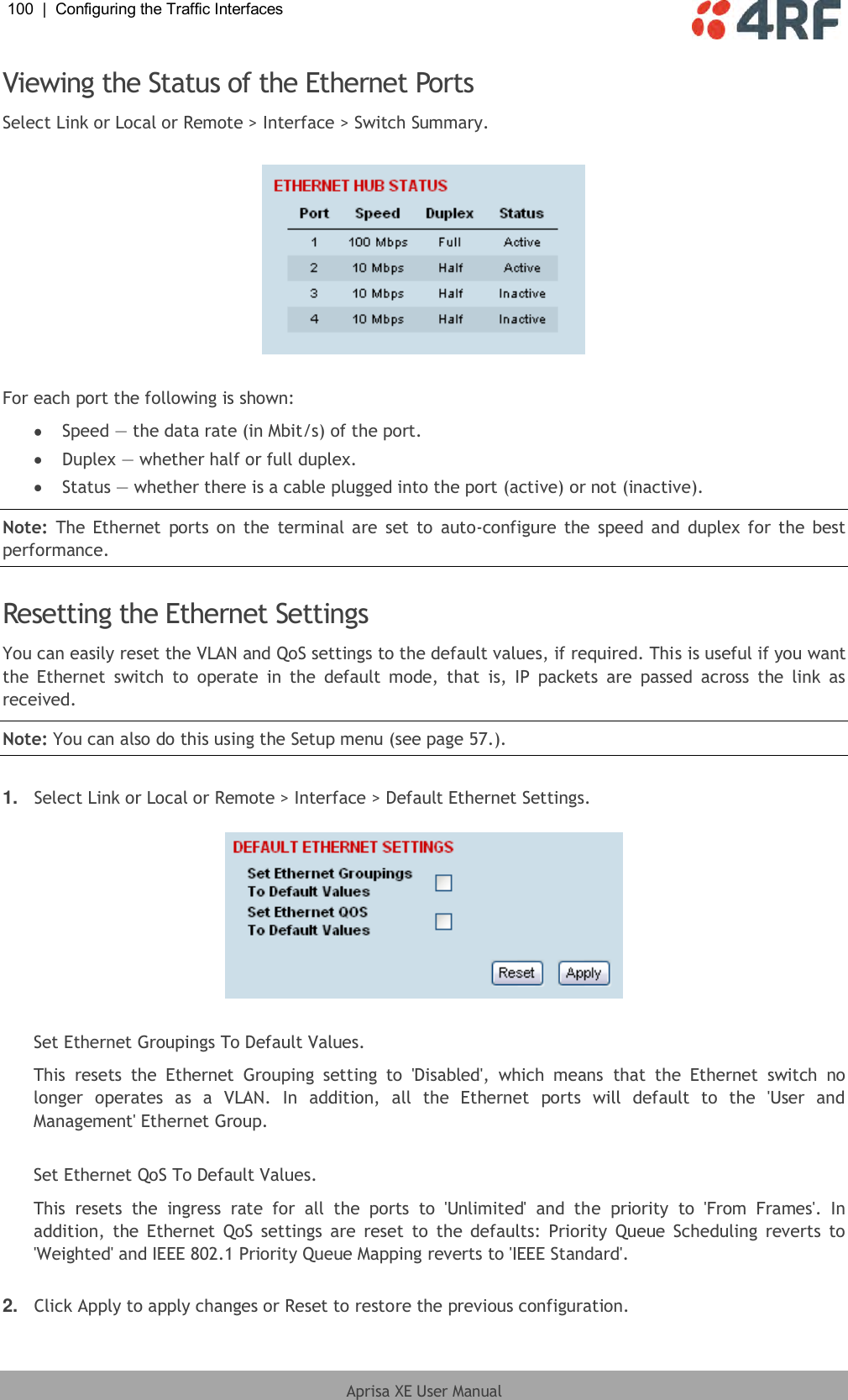
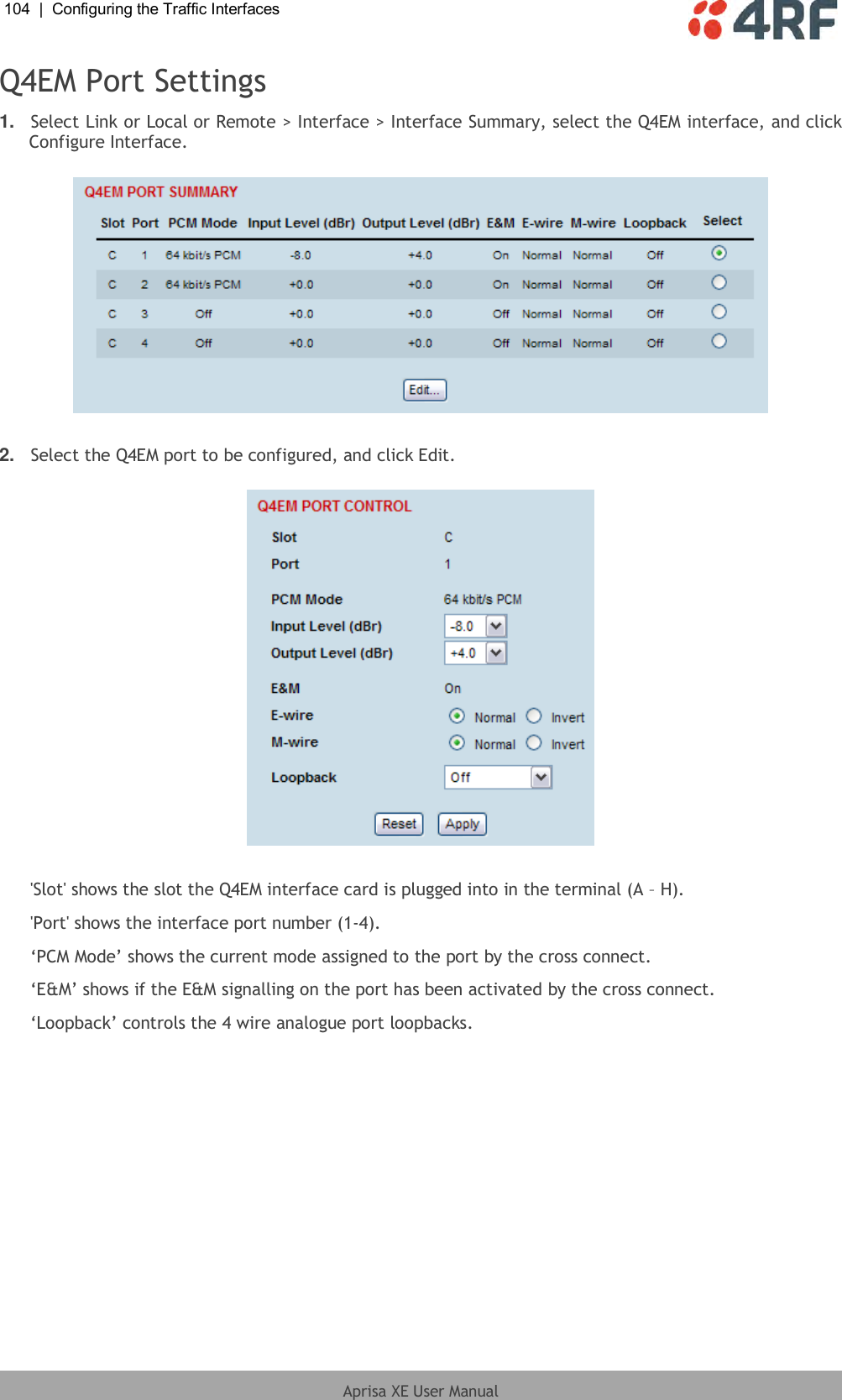
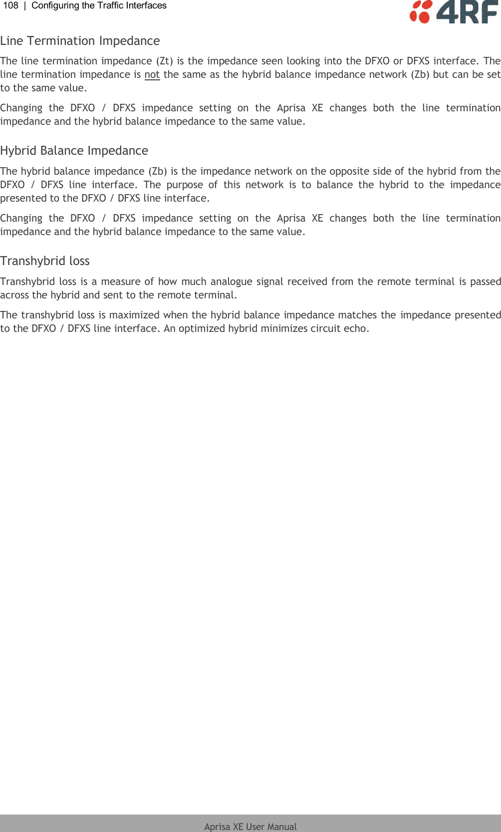
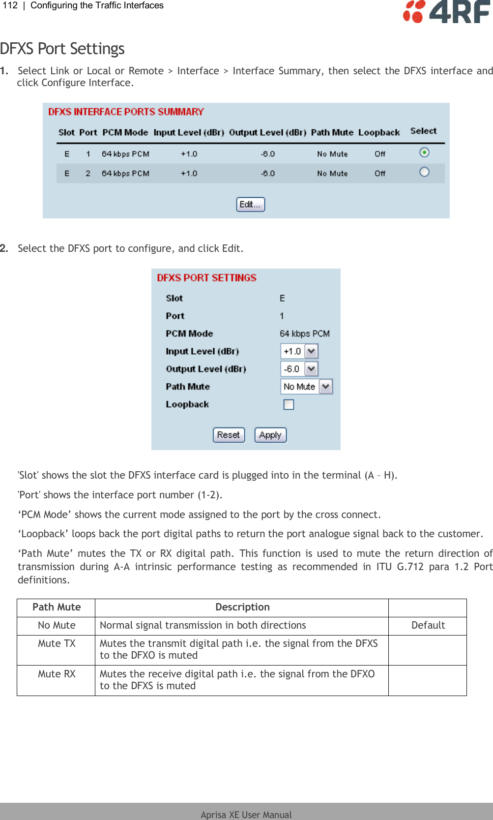
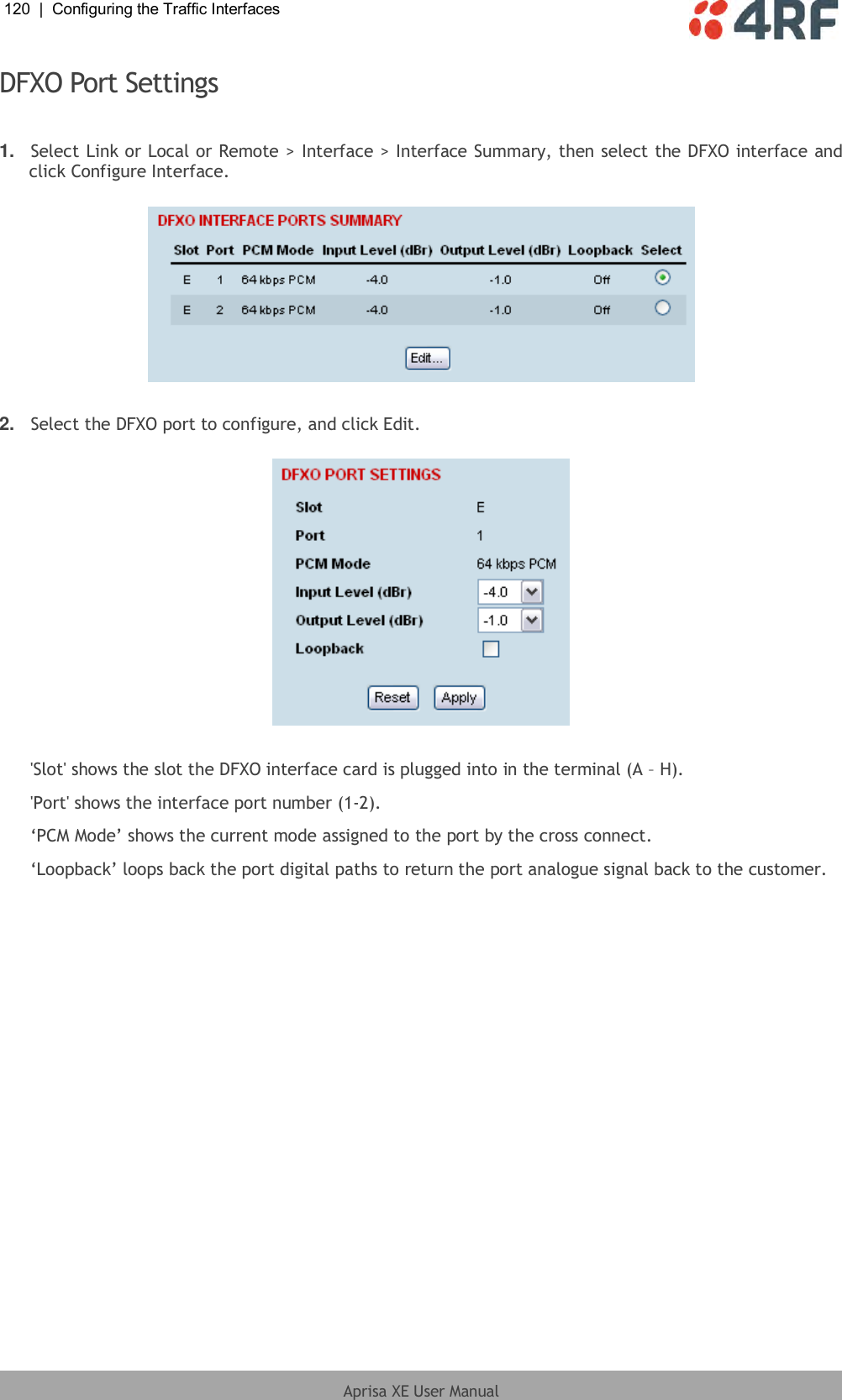
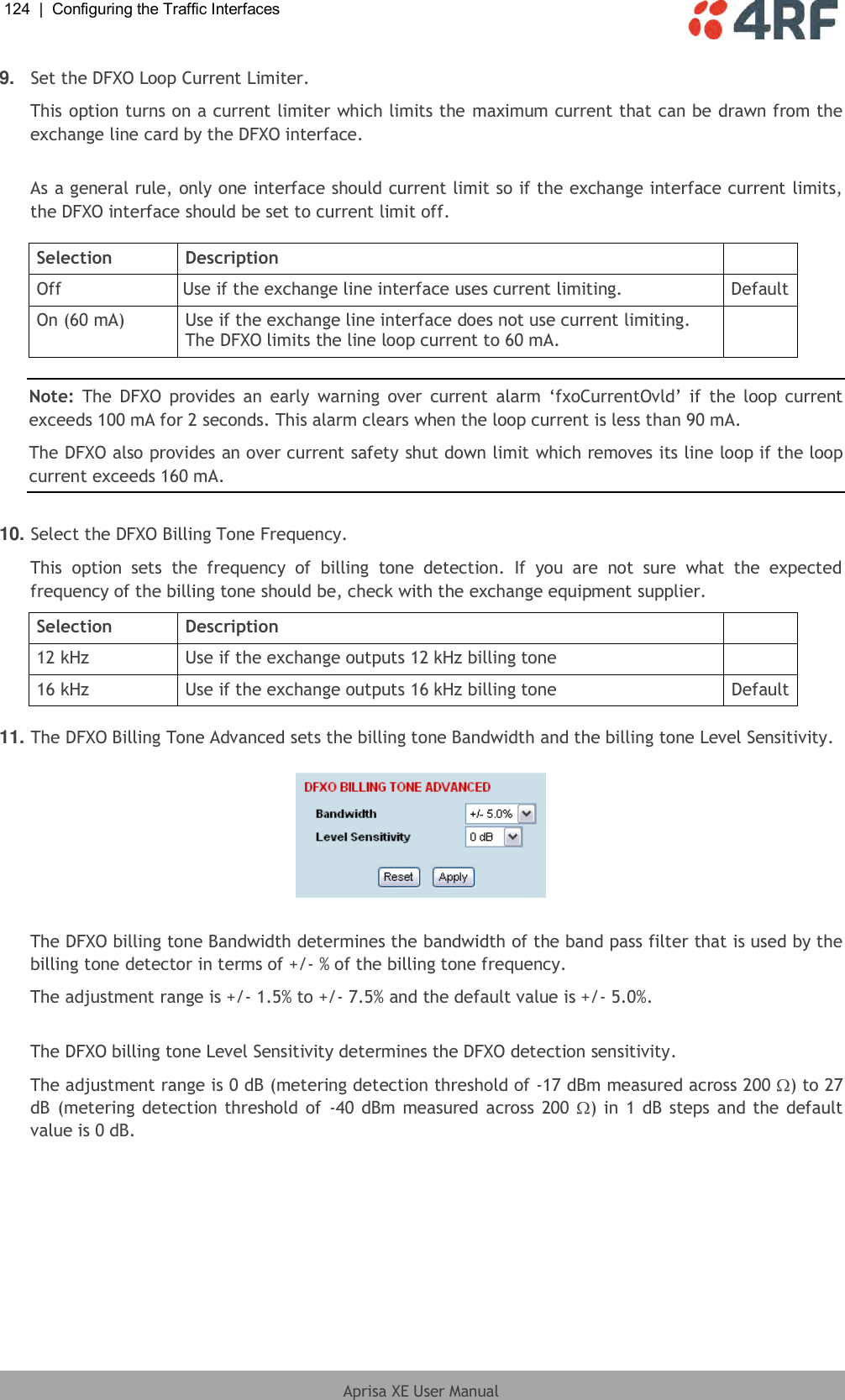
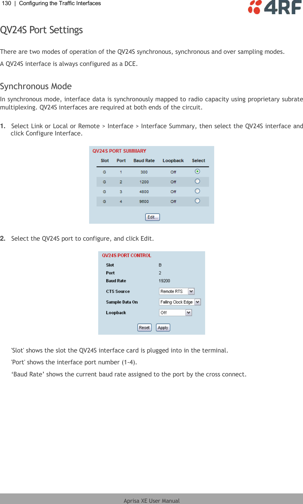
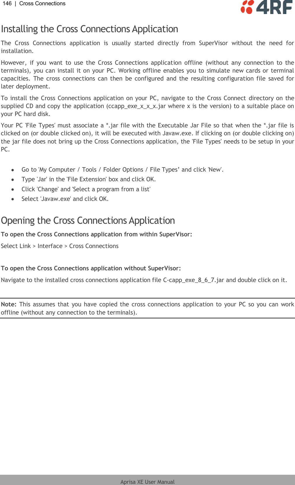
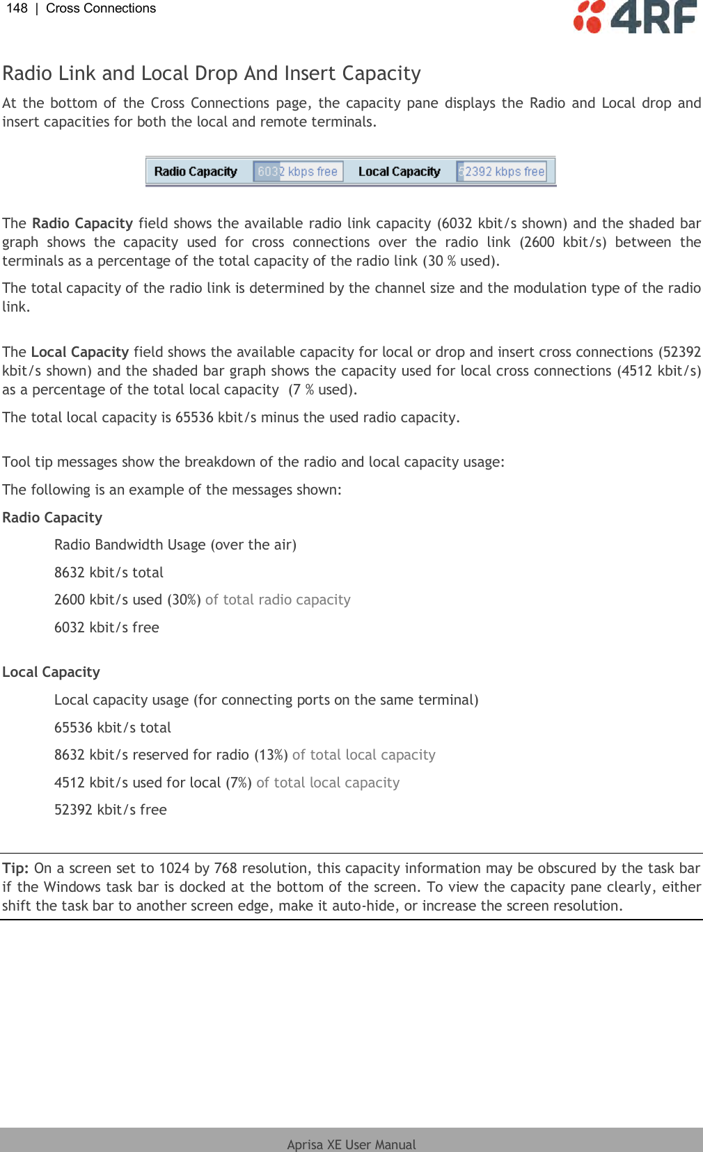
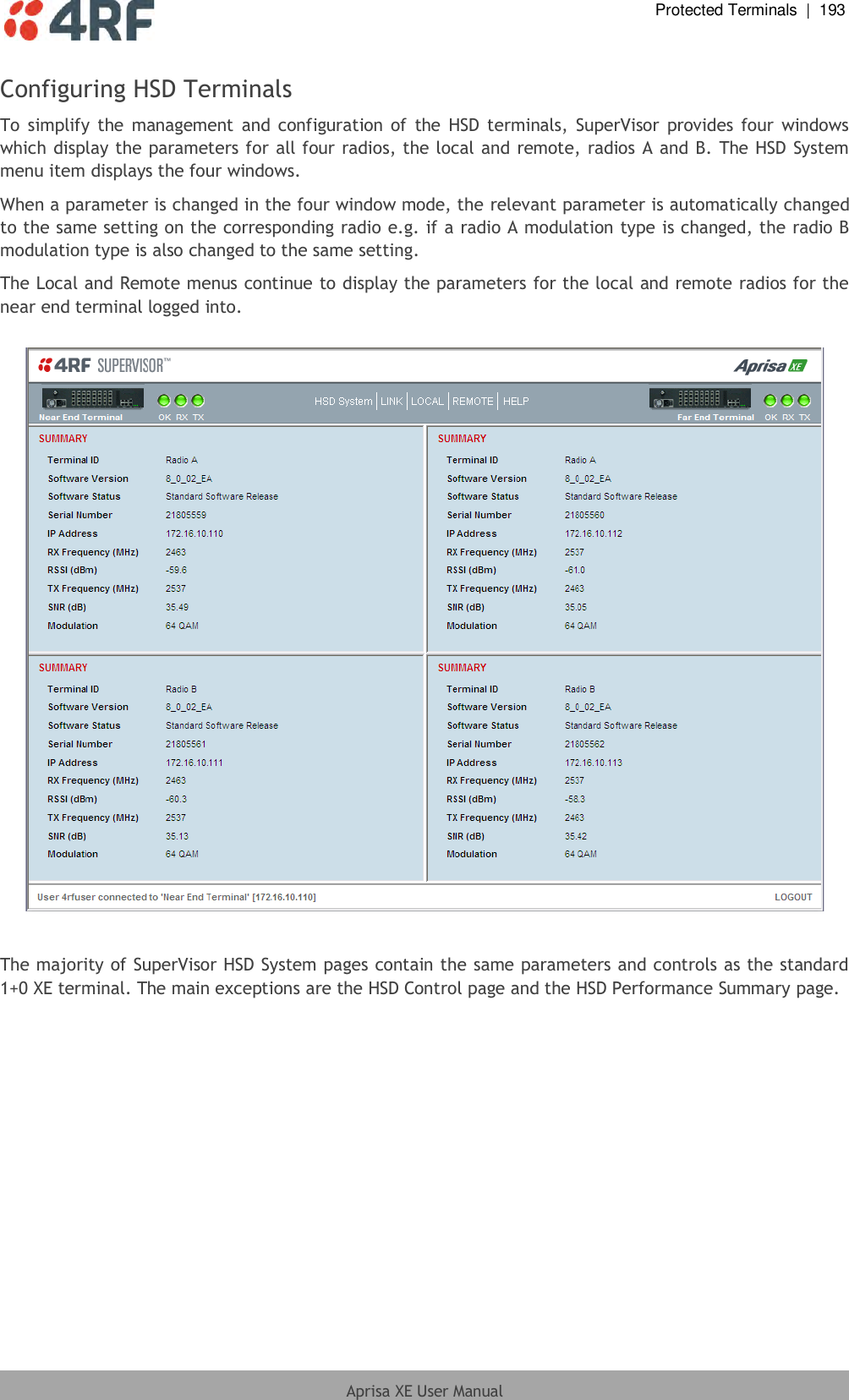
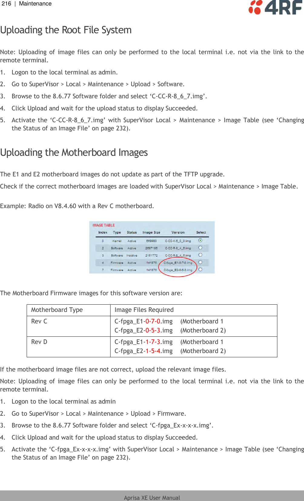
![Maintenance | 223 Aprisa XE User Manual Step 5: Run the TFTP upgrade process on the Local terminal. 1. Select Local > Maintenance > Upload > TFTP Upgrade. 2. Enter the IP address of the TFTP server (that you noted earlier) 3. Enter the version number of the software (that you are upgrading to) for example, 8_6_77_E0. 4. Click Apply and check the TFTP server for download activity. The Upgrade Result changes from 'Executing' to either 'Succeeded' or 'Failed'. Note: This may take several minutes when upgrading the remote terminal. Step 6: Reboot the Local terminal Reboot the local terminal before proceeding with the next step of the upgrade process (see ‘Rebooting the Terminal’ on page 233). 1. Select Local > Maintenance > Reboot and select [Hard Reboot] 2. Log back into the Local terminal when the reboot has completed. Step 7: Clear the Java and web browser caches After upgrading the terminal you should clear the Java and web browser caches. The files stored in them may cause the SuperVisor and Cross Connections applications to display incorrectly. To clear the Java cache (Windows XP, Java 1.6): 1. Select Start > Control Panel. 2. Select Java 3. Click the General tab. 4. In the ‘Temporary Internet Files’, click Settings 5. Click on ‘Delete Files’ (‘Applications and Applets’ and ‘Trace and Log Files’ both ticked) and OK to confirm.](https://usermanual.wiki/4RF/XE20001300/User-Guide-1961219-Page-226.png)