ACSS an L 3 Communications and Thales TT-950 TCAS II User Manual Part 1
ACSS an L-3 Communications and Thales Company TCAS II Part 1
UserManual.wiki
>
ACSS an L 3 Communications and Thales
>
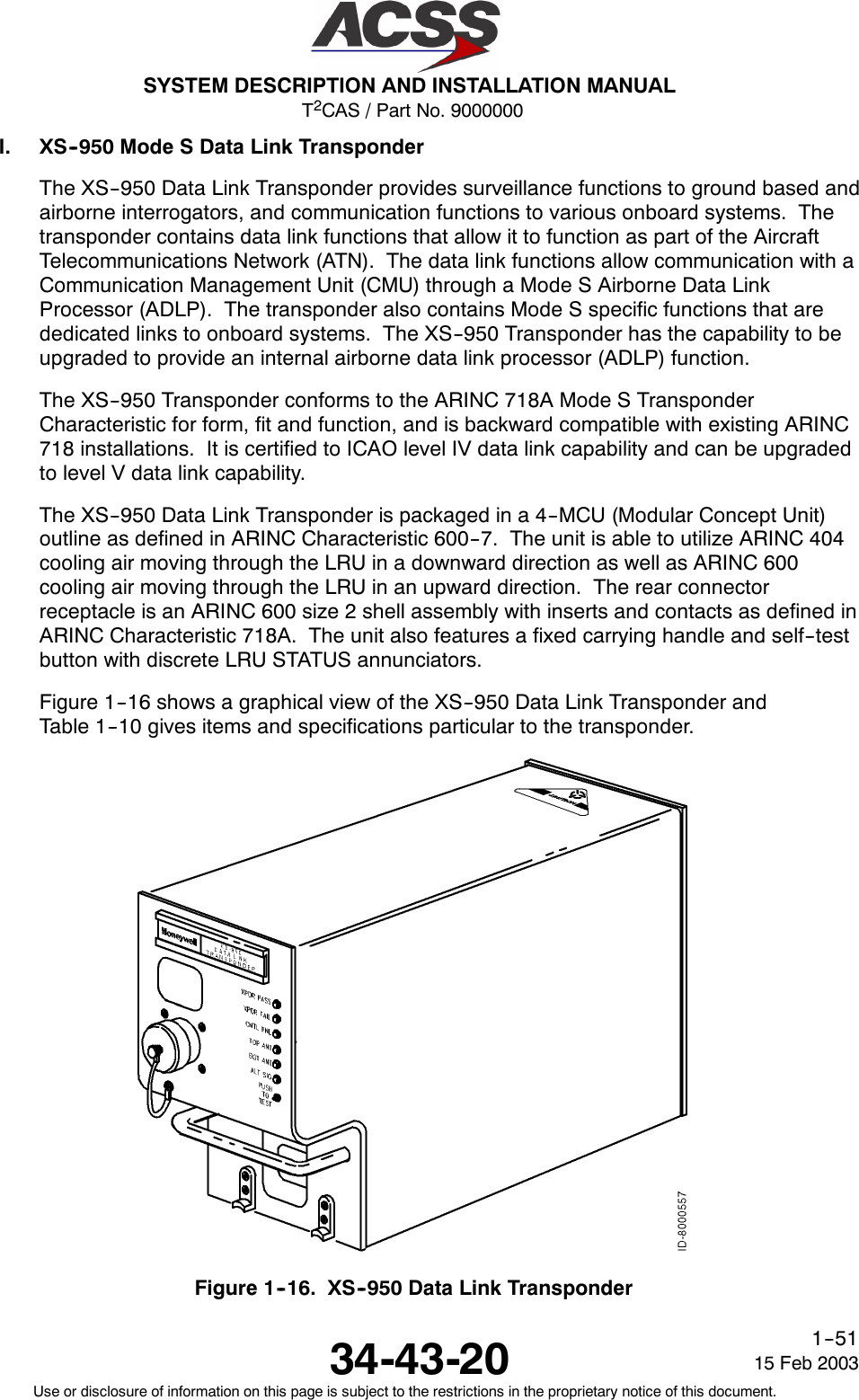
TT-950 User Manual
>
User Manual Part 1
Contents
1.
User Manual Part 1
2.
User Manual Part 2
User Manual Part 1
Navigation menu
Upload a User Manual
Namespaces
Wiki Guide
HTML
PDF
Info
Views
User Manual
Discussion / Help
Navigation

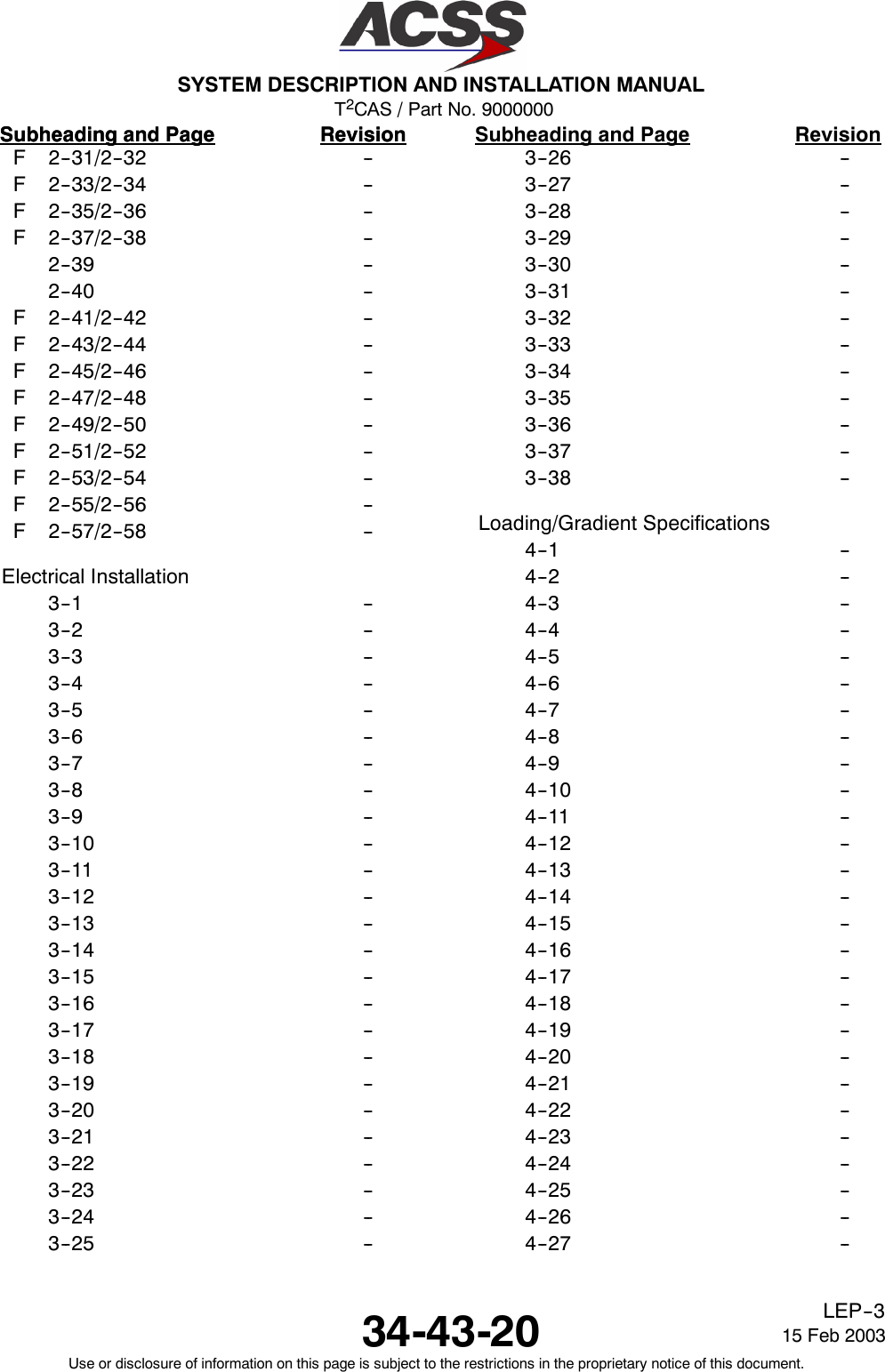

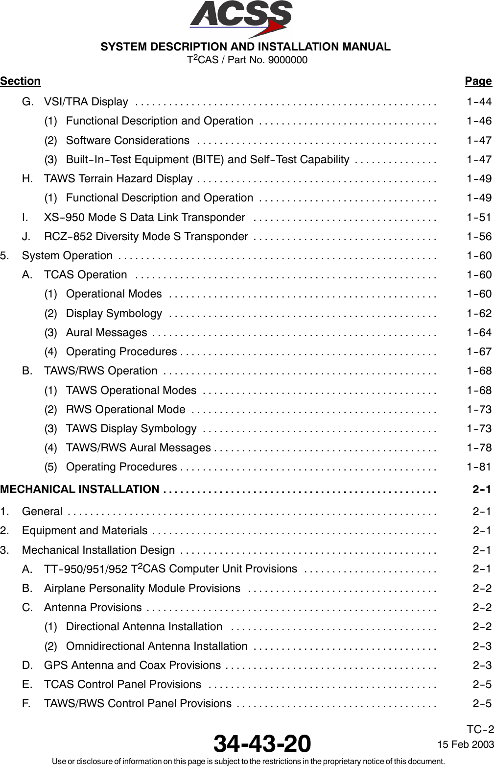
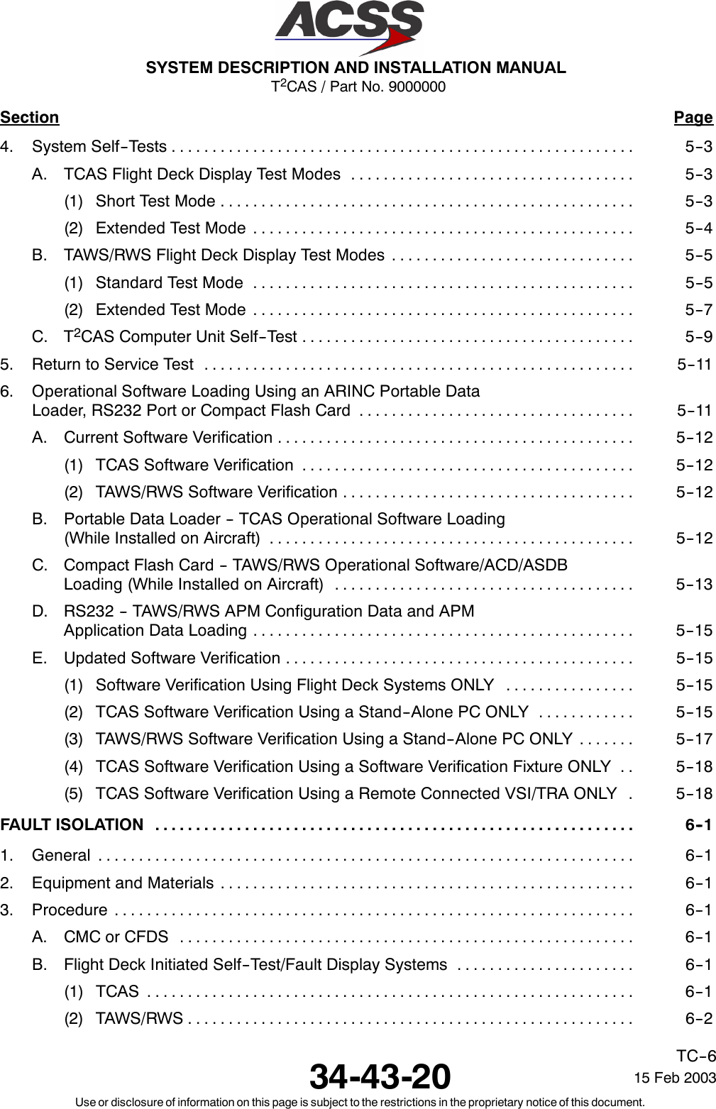
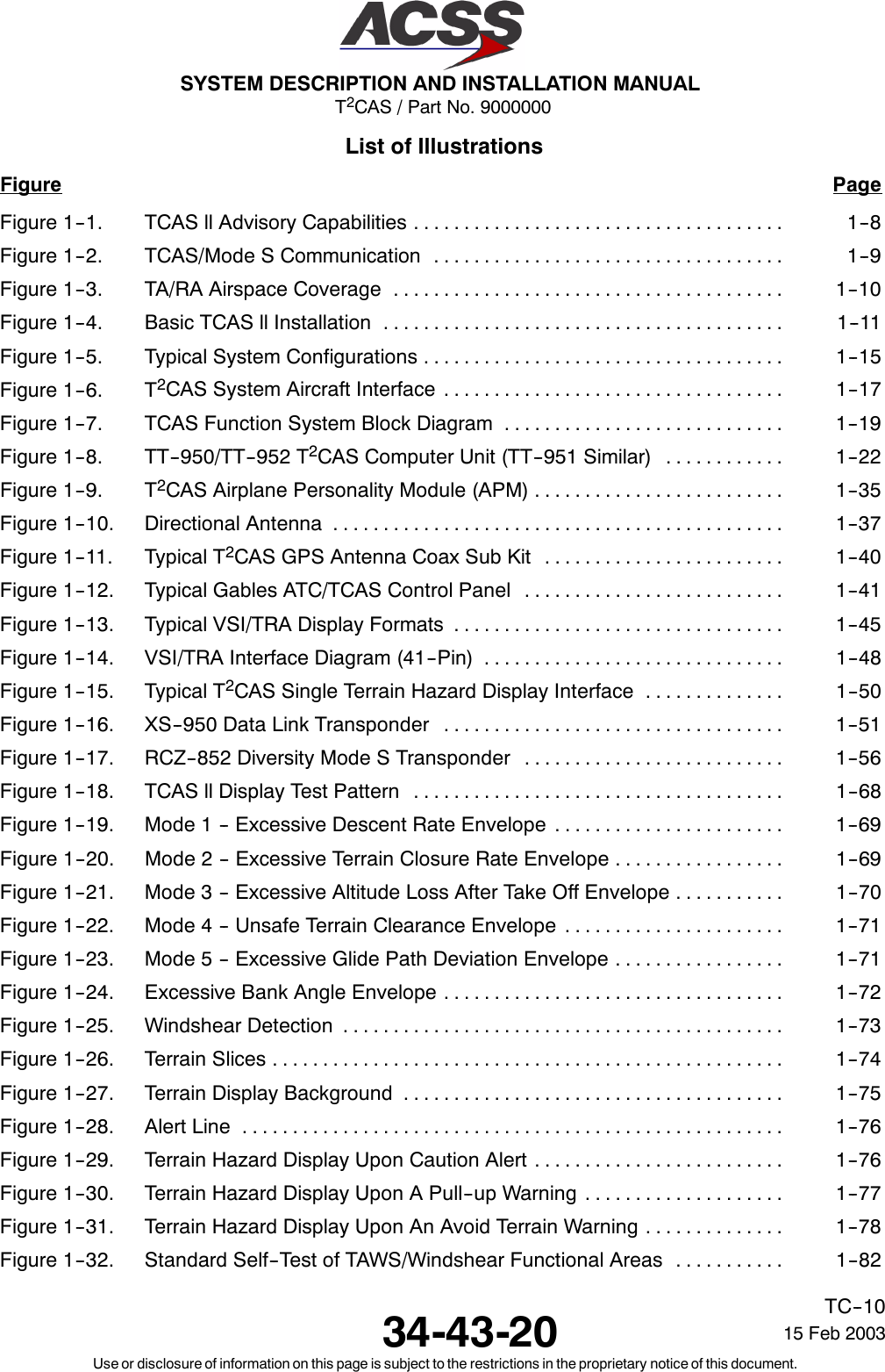
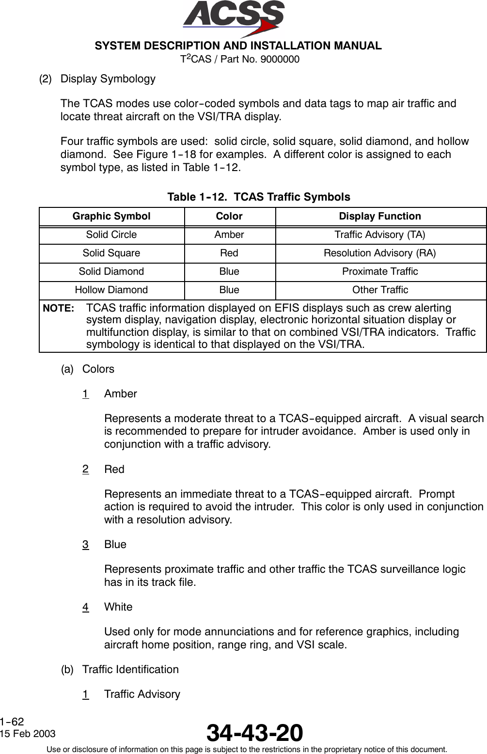
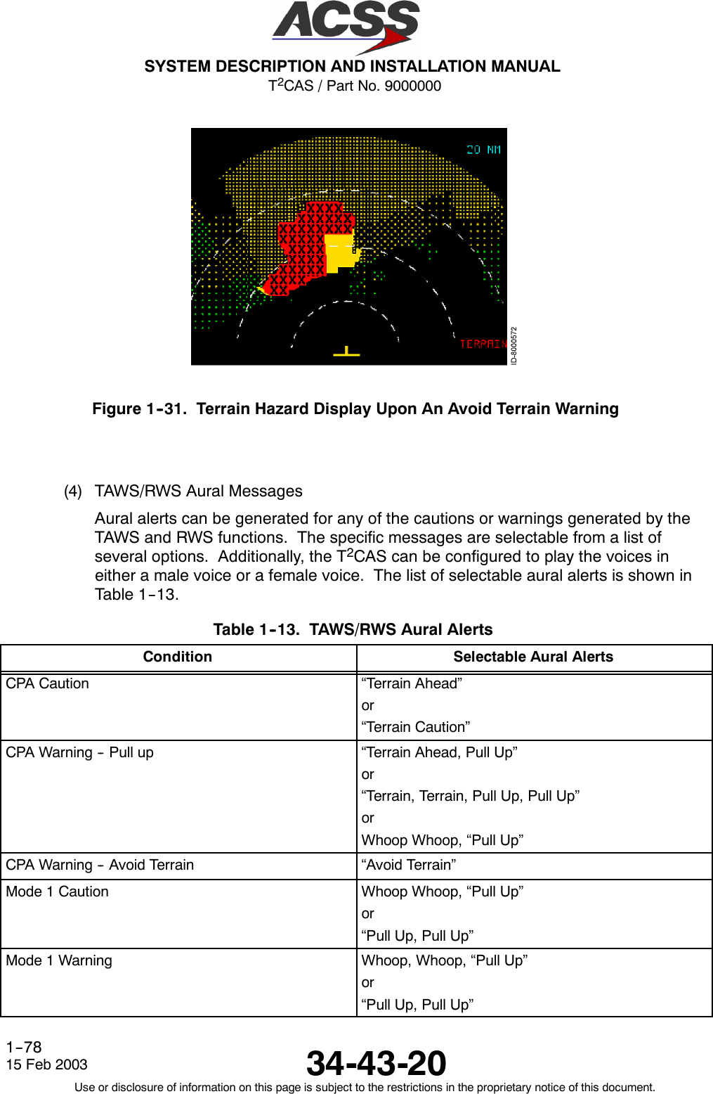
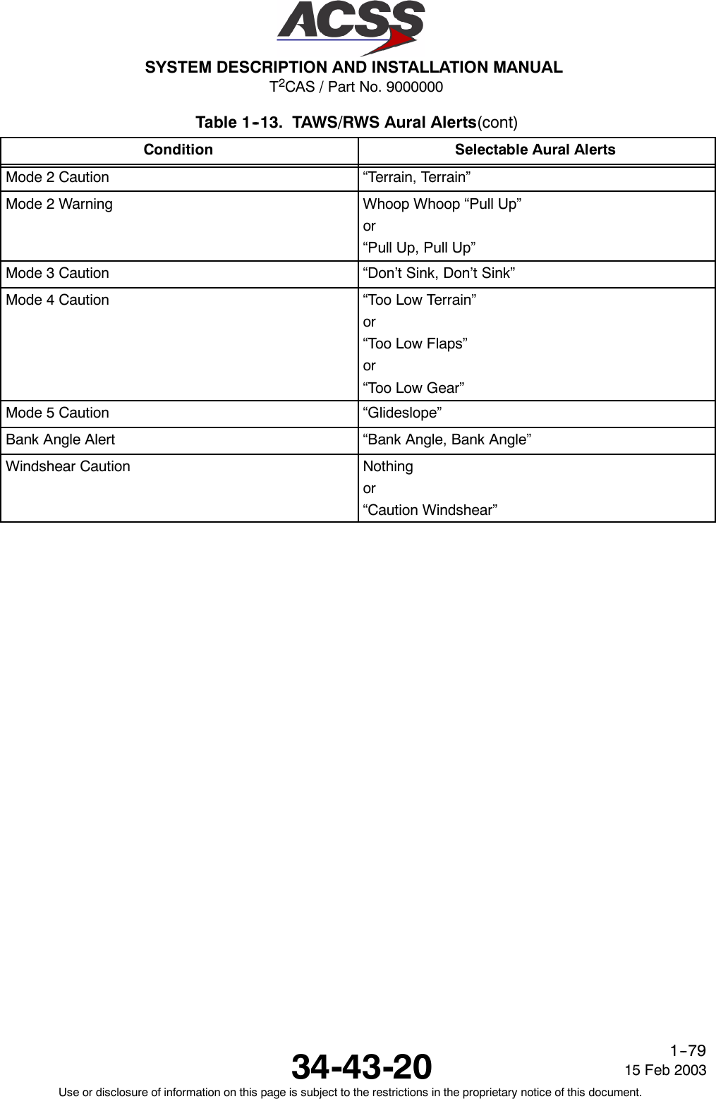
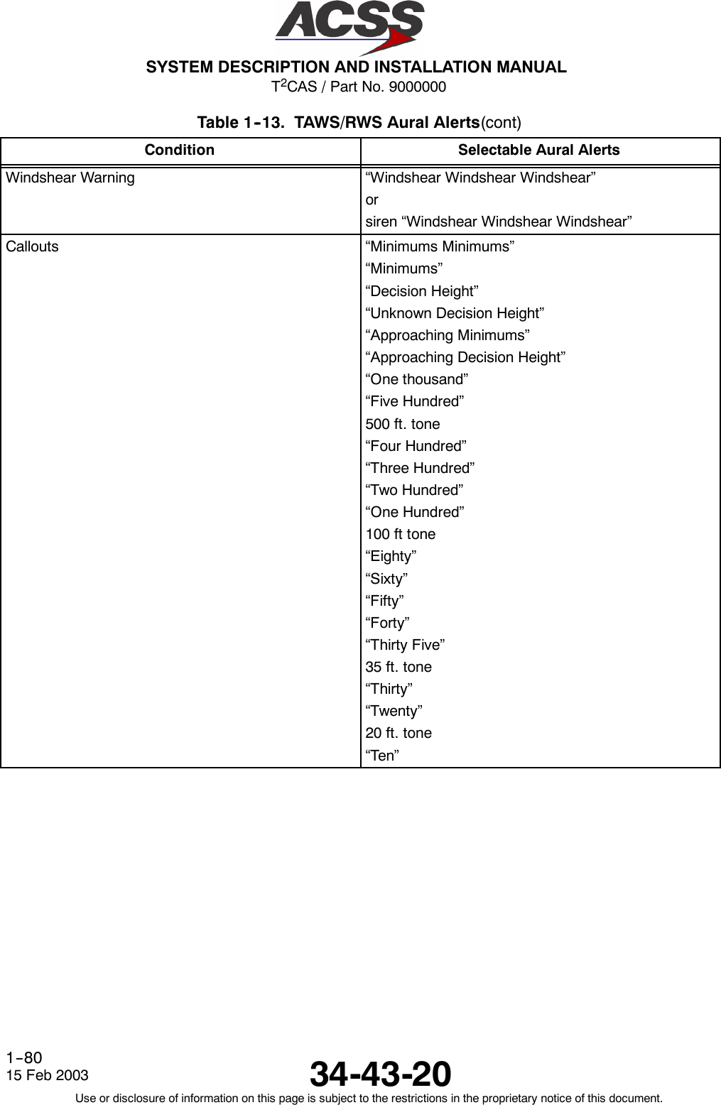
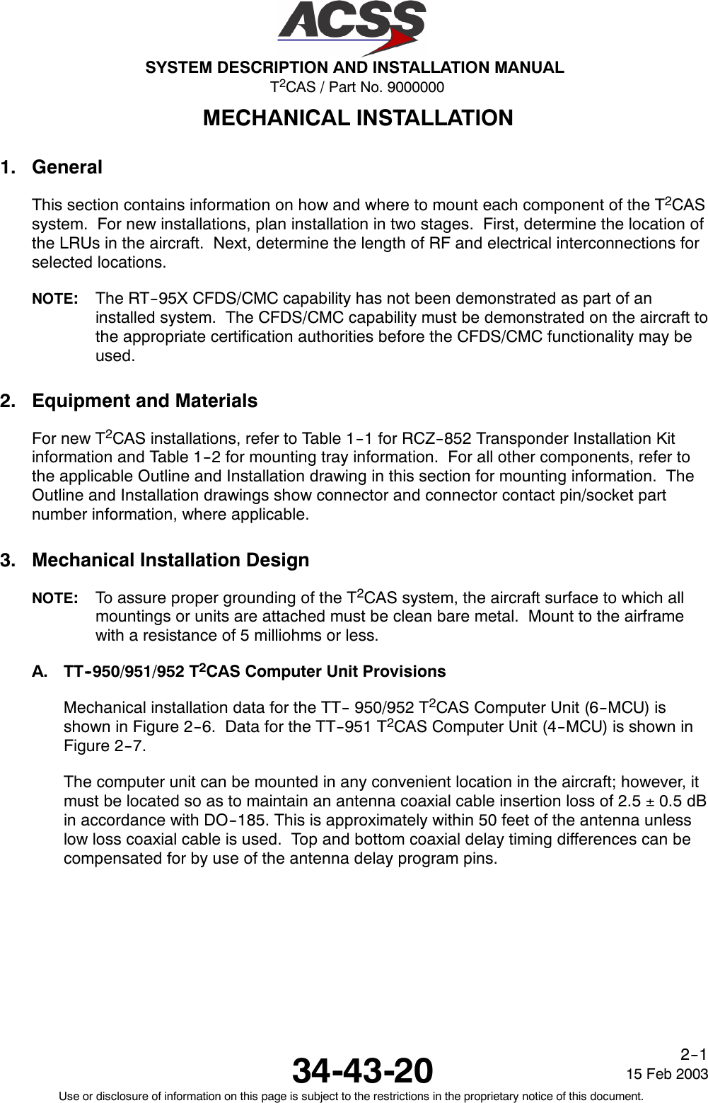
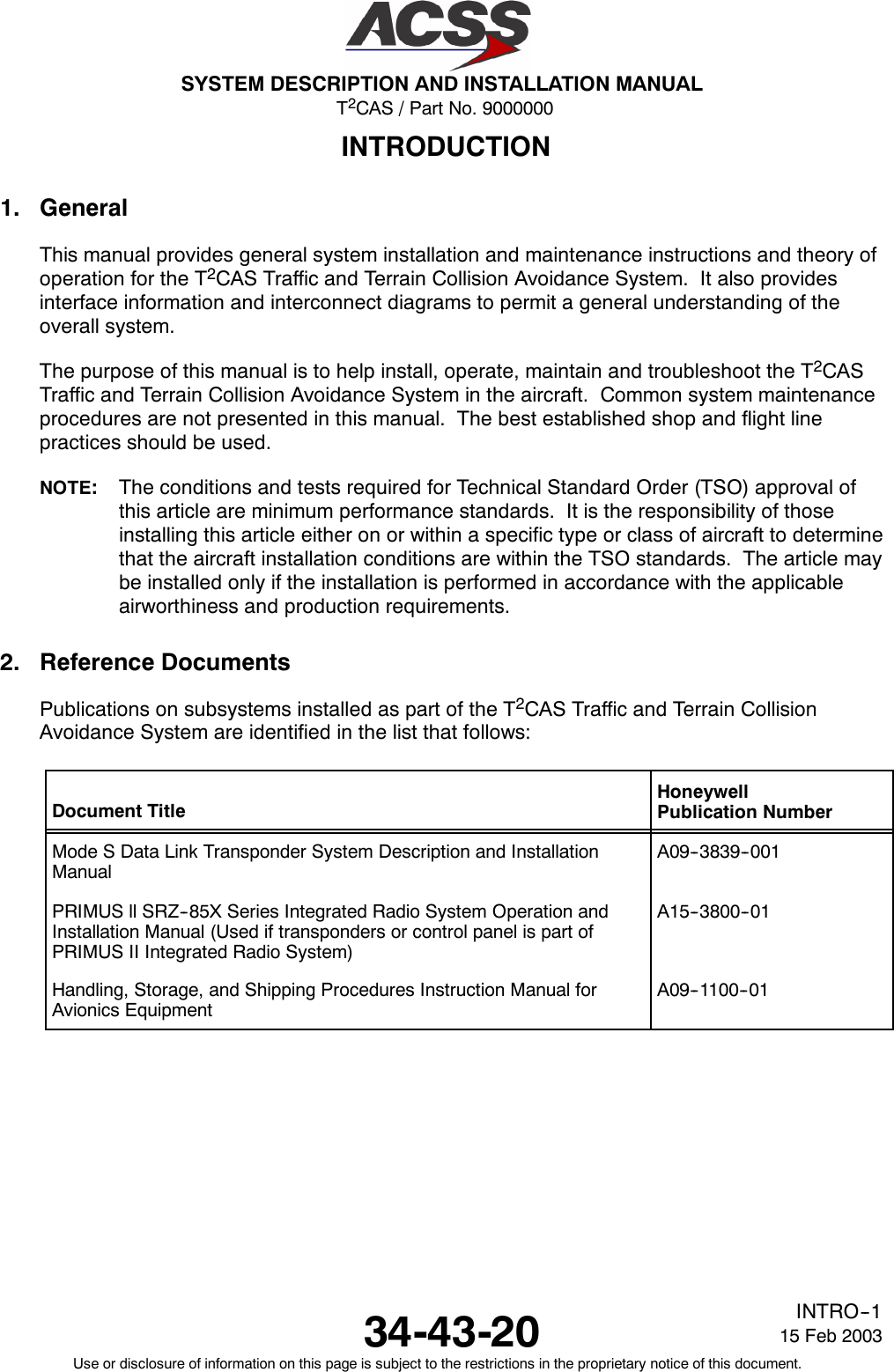
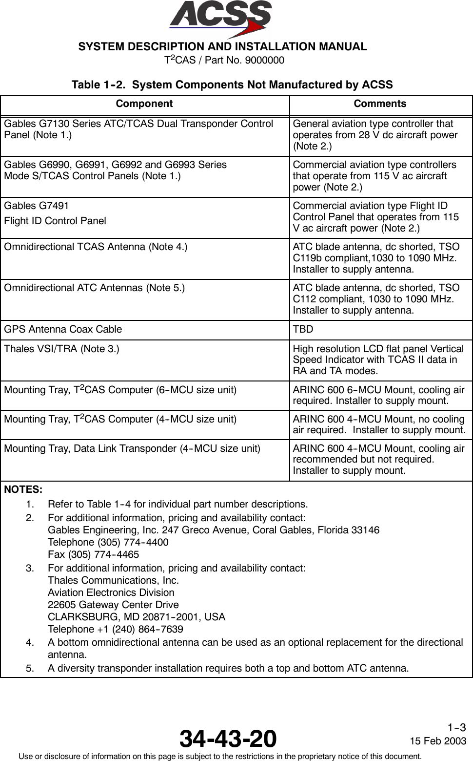
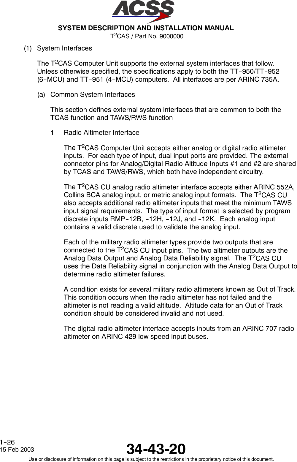
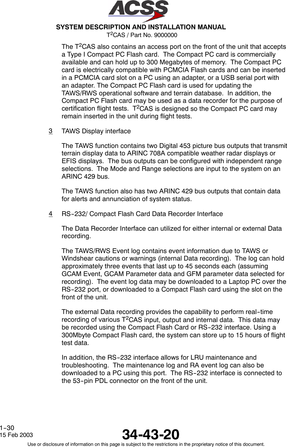
![T2CAS / Part No. 9000000SYSTEM DESCRIPTION AND INSTALLATION MANUAL34-43-20 15 Feb 2003Use or disclosure of information on this page is subject to the restrictions in the proprietary notice of this document.TC--14List of Tables (cont)Table PageTable 4--11. Analog Input Impedance 4--67........................................Table 4--12. 3W Synchro AC References 4--67.....................................Table 4--13. APM/ASDB Programmable Digital Inputs 4--68..........................Table 4--14. APM/ASDB Programmable Digital Outputs 4--69........................Table 4--15. Source Destination Identifier (SDI) 4--70................................Table 4--16. Sign Status Matrix (SSM) [BNR] 4--70..................................Table 4--17. Sign Status Matrix (SSM) [BCD] 4--71..................................Table 4--18. APM/ASDB Programmable Discrete Inputs 4--72........................Table 4--19. APM/ASDB Programmable Discrete Outputs 4--73......................Table 4--20. Navigation Accuracy 4--79............................................Table 4--21. True Display Orientation Left 4--84.....................................Table 4--22. True Display Orientation Right 4--84...................................Table 4--23. A429 Output Bus GCAM Event Data Labels 4--87.......................Table 4--24. OMS Label 350 Discretes 4--89.......................................Table 4--25. OMS Label 351 Discretes 4--90.......................................Table 4--26. OMS Label 352 Discretes 4--91.......................................Table 5--1. Equipment 5--1....................................................Table 5--2. Computer Unit Harness Checkout 5--1...............................Table 5--3. Extended Test Menu Selections 5--5.................................Table 5--4. Compact Flash Upload / LED correlation 5--13..........................Table 6--1. TCAS Aural and VSI/TRA Annunciations 6--4.........................Table 6--2. System Status Page Fault Messages 6--8............................Table 6--3. Computer Unit Self--Test Execution 6--26..............................Table 6--4. TCAS Fault Reporting and Corrective Actions 6--28.....................Table 6--5. Antenna Wiring Resistance 6--29......................................Table 7-- 1. Materials 7--1.....................................................Table 9--1. Equipment and Materials 9--1.......................................Table 10--1. LRU Maintenance Manual 10--1......................................Table B--1. Aircraft Configuration B--3...........................................](https://usermanual.wiki/ACSS-an-L-3-Communications-and-Thales/TT-950.User-Manual-Part-1/User-Guide-302827-Page-28.png)
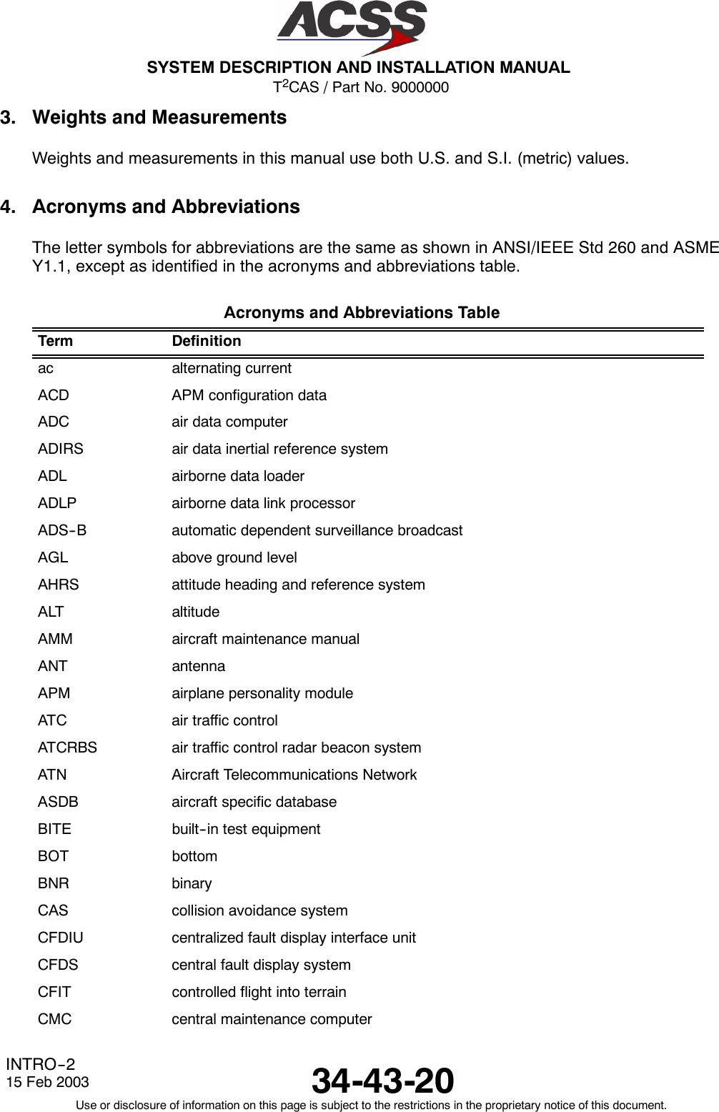
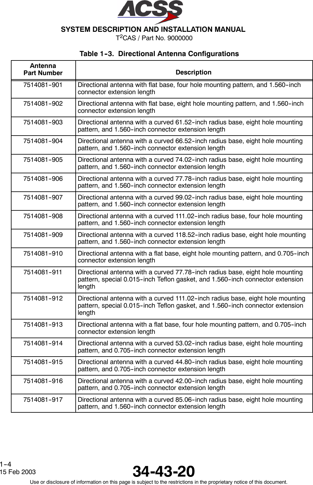

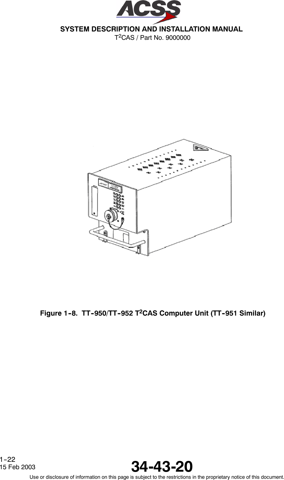
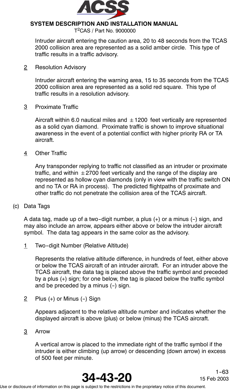
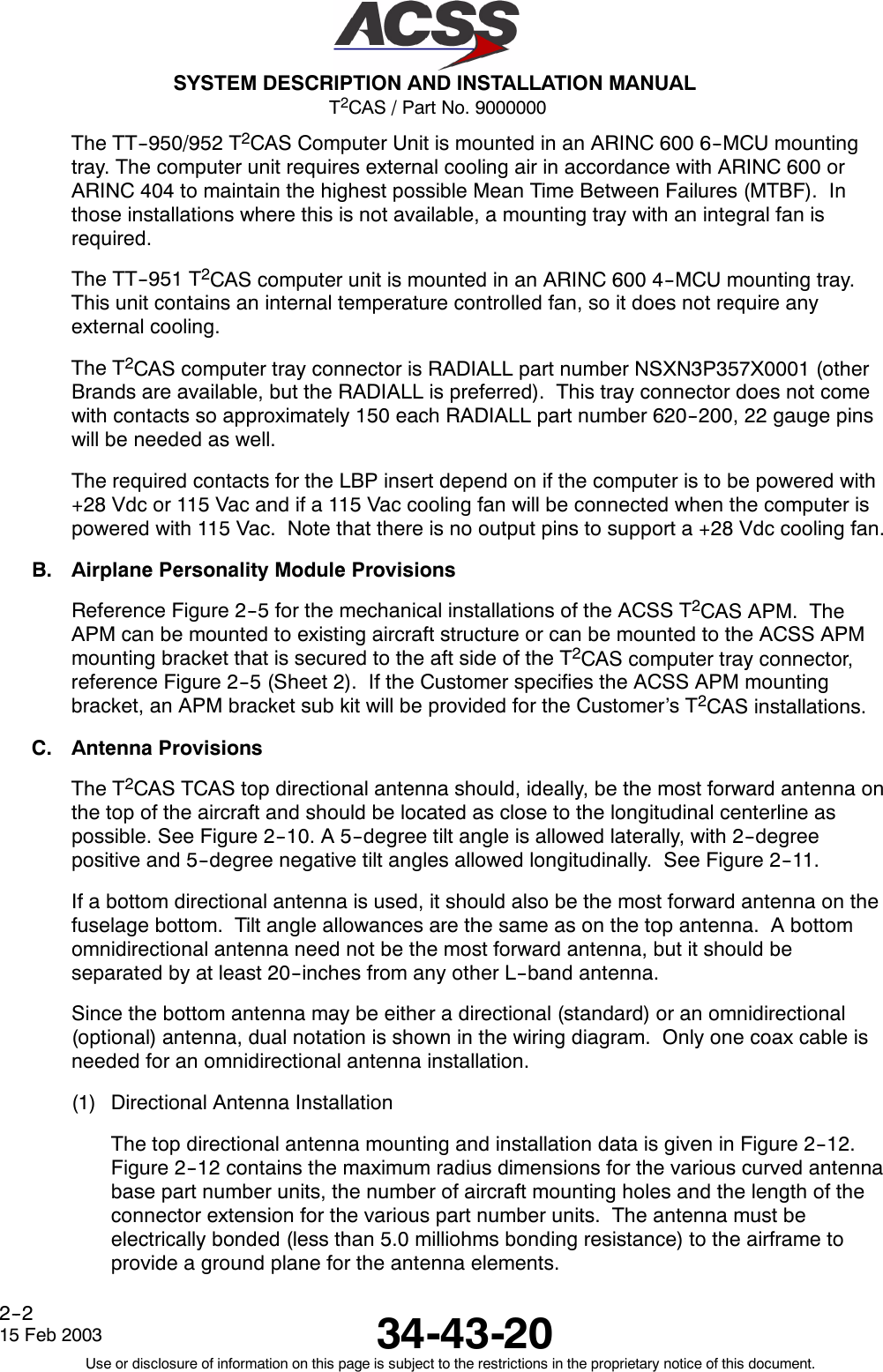
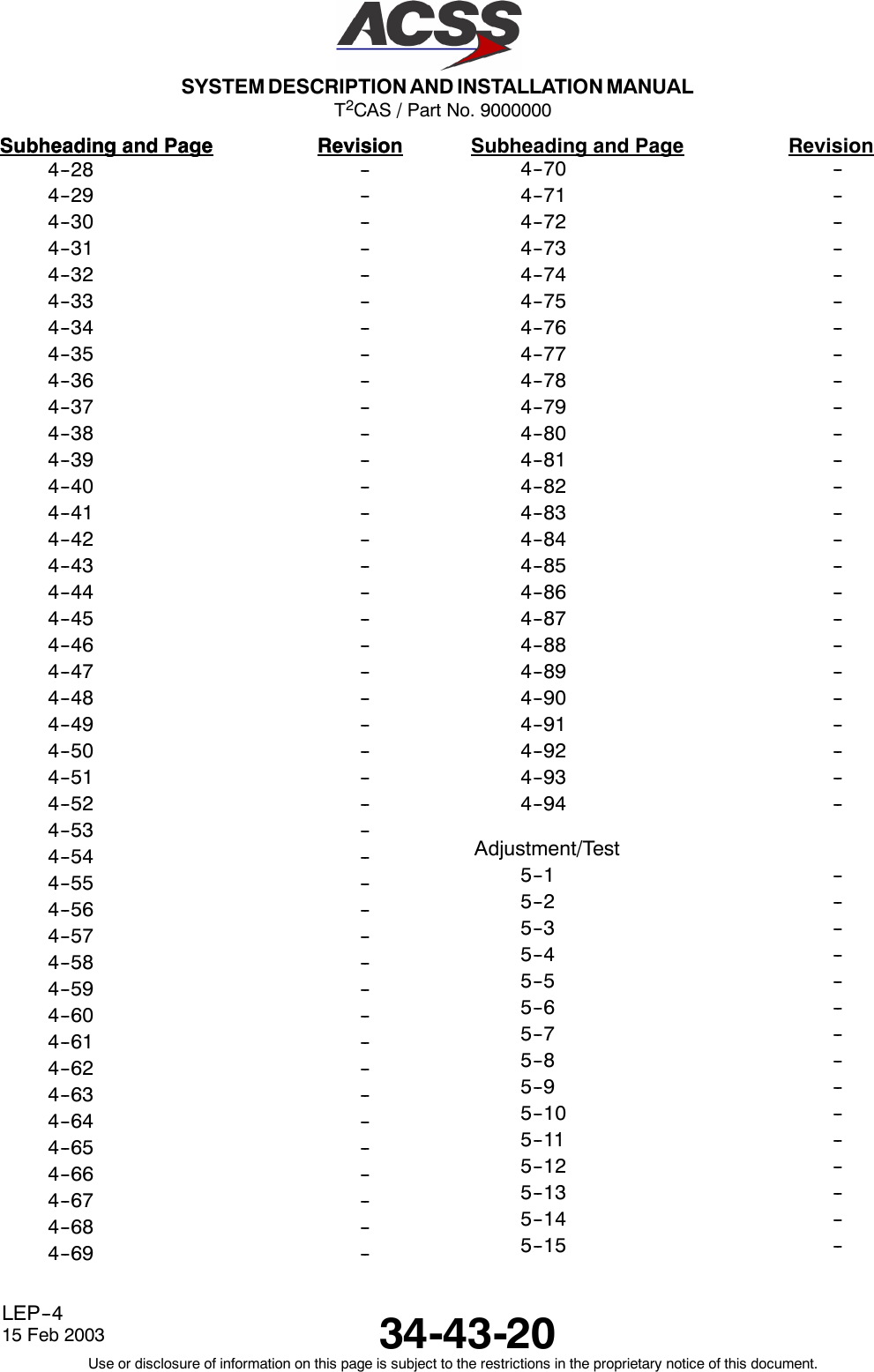
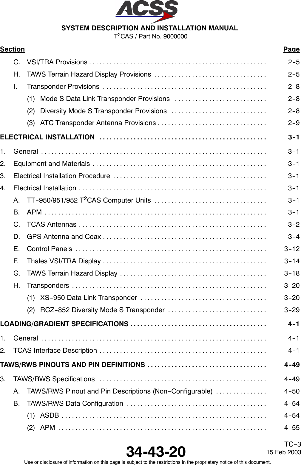
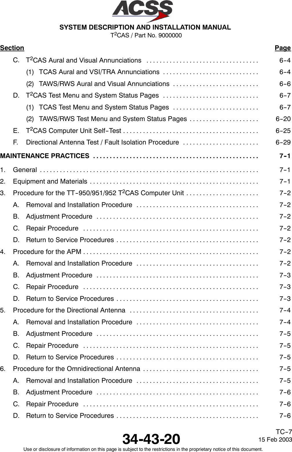
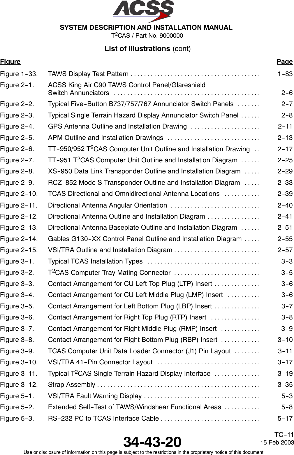
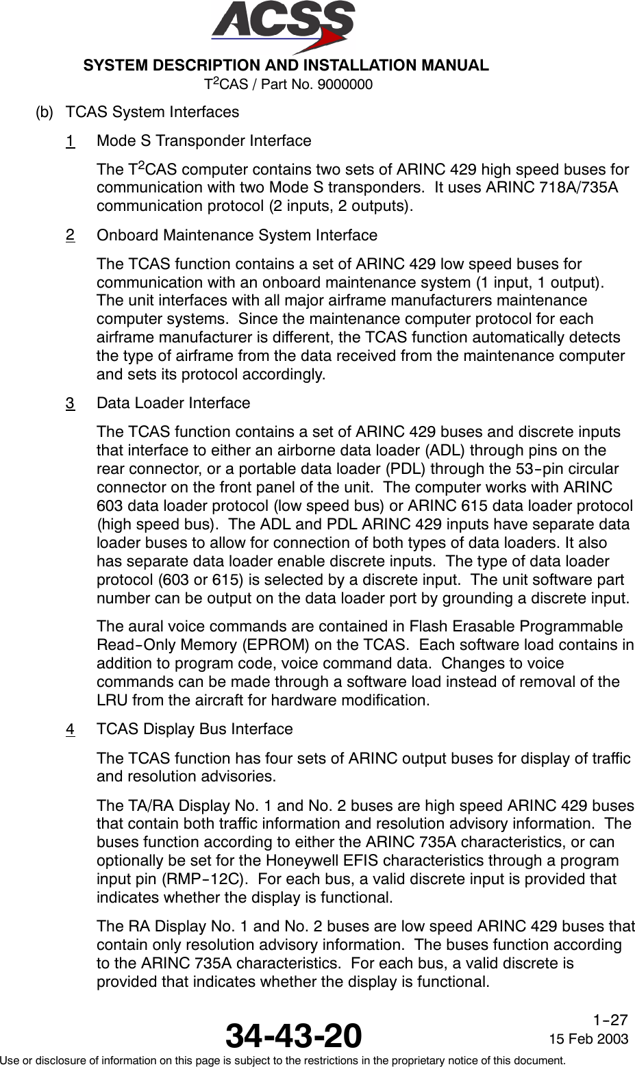
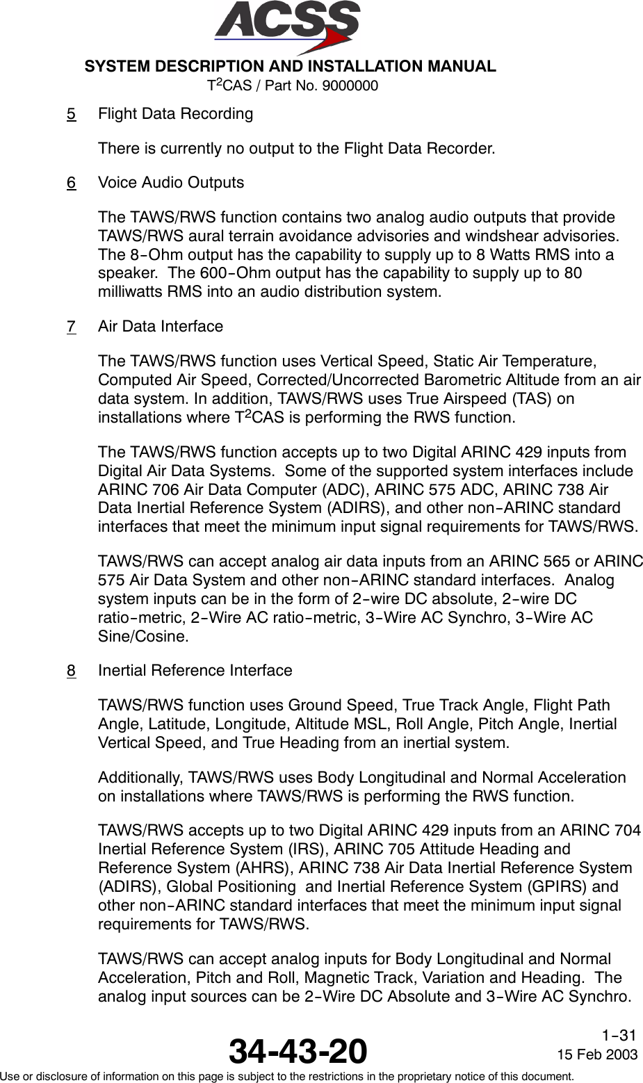
![T2CAS / Part No. 9000000SYSTEM DESCRIPTION AND INSTALLATION MANUAL34-43-2015 Feb 2003Use or disclosure of information on this page is subject to the restrictions in the proprietary notice of this document.1--24Table 1--6. TT--950/951/952 T2CAS Computer Unit Leading Particulars (cont)Item Specification-- FanOff(controlledbytemperaturesensor) ..... Temp sensor < +25 Deg CMounting:•TT--950/TT--952 ............................... ARINC 600 6--MCU Tray Assembly•TT--951 ...................................... ARINC 600 4--MCU Tray AssemblyTSO:AllUnits(TCAS/TAWS) ..........................All Units (with Reactive Windshear) ................TT--952(withGPS) .............................C119b (with deviation)2, C151AC117AC129ASoftwareDevelopmentSpecification ............... DO--178B, Level BEnvironmental Specifications (TT--950/--952) ........ DO--160D (with deviation)1Environmental Category [(A2)(F2)Y]BBB[(HBR)(RB1)(SM)]EXXXXXZ[EBZ]A[EZ]Z[RR]M[A3E3]XXAEnvironmental Specifications (TT--951) ............. DO--160D (with deviation)1Environmental Category [(A2)(F2)X]BBB[(HBR)(RB1)(SM)]EXXXXXZ[BZ]AZZ[RR]M[A3E3]XXA•Temperature / Altitude [A2F2]:-- OperatingTemperature ...................... --55 to +70 degrees C-- Ground Survival Temperature ................ --55 to +85 degrees C-- Altitude .................................... Sea Level to 55,000 feet-- LossofCooling ............................. +40 degrees C for 300 minutes minimumRF Transmitter Characteristics:•Transmitter Frequency ......................... 1030 ±0.01 MHz•RF Peak Output Power:-- Minimum................................... 53.3 dBm (210 Watts)-- Nominal ................................... 55.3 dBm (335 Watts)-- Maximum .................................. 57.3 dBm (540 Watts)•UnwantedOutputPowerinanInactiveState...... --72 dBm](https://usermanual.wiki/ACSS-an-L-3-Communications-and-Thales/TT-950.User-Manual-Part-1/User-Guide-302827-Page-57.png)
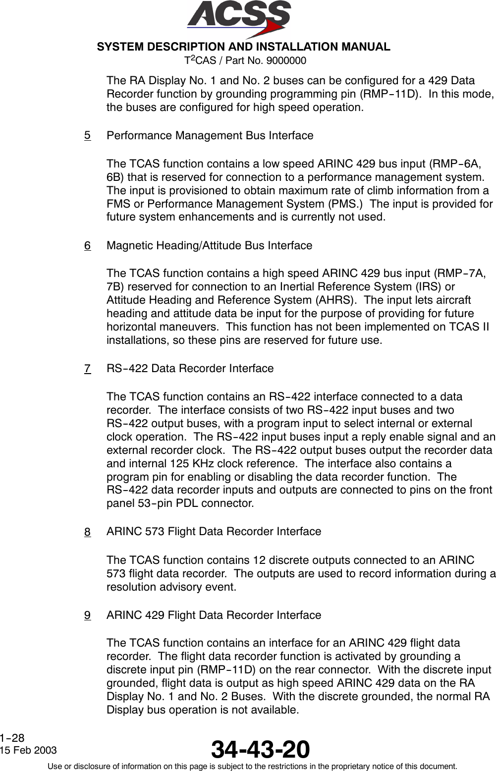
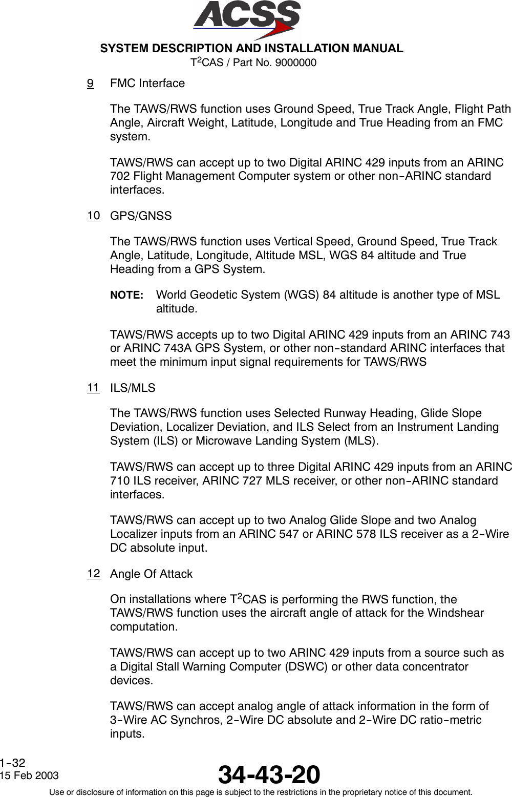
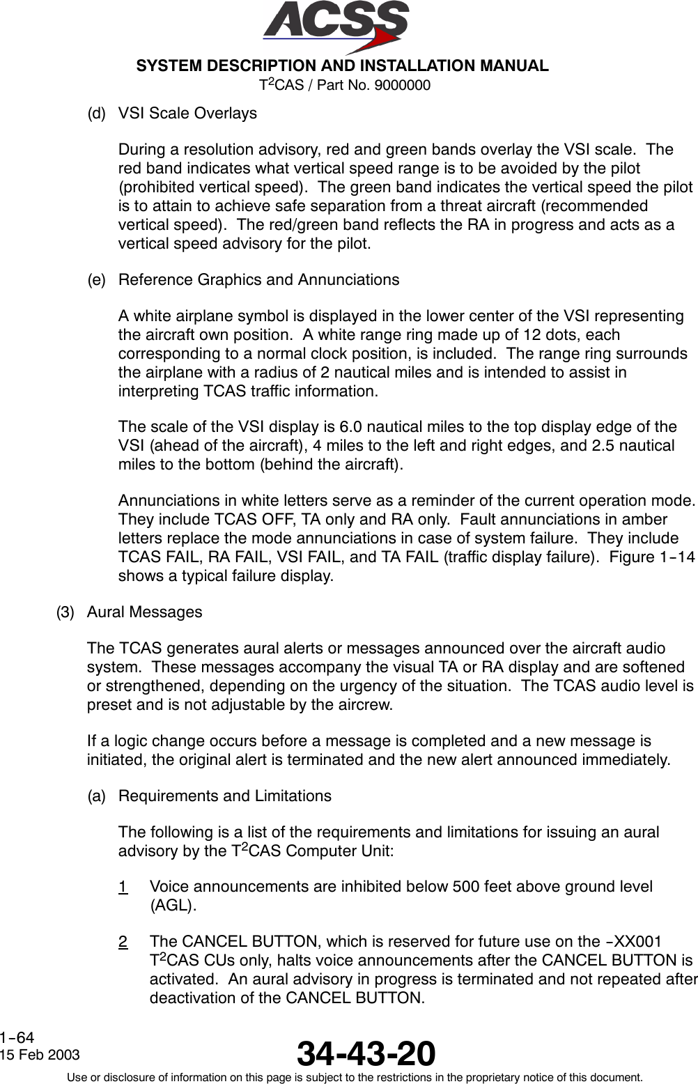
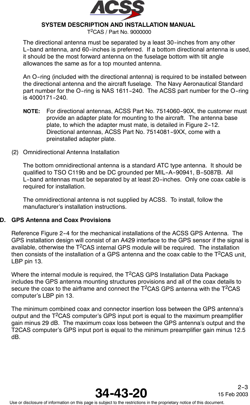
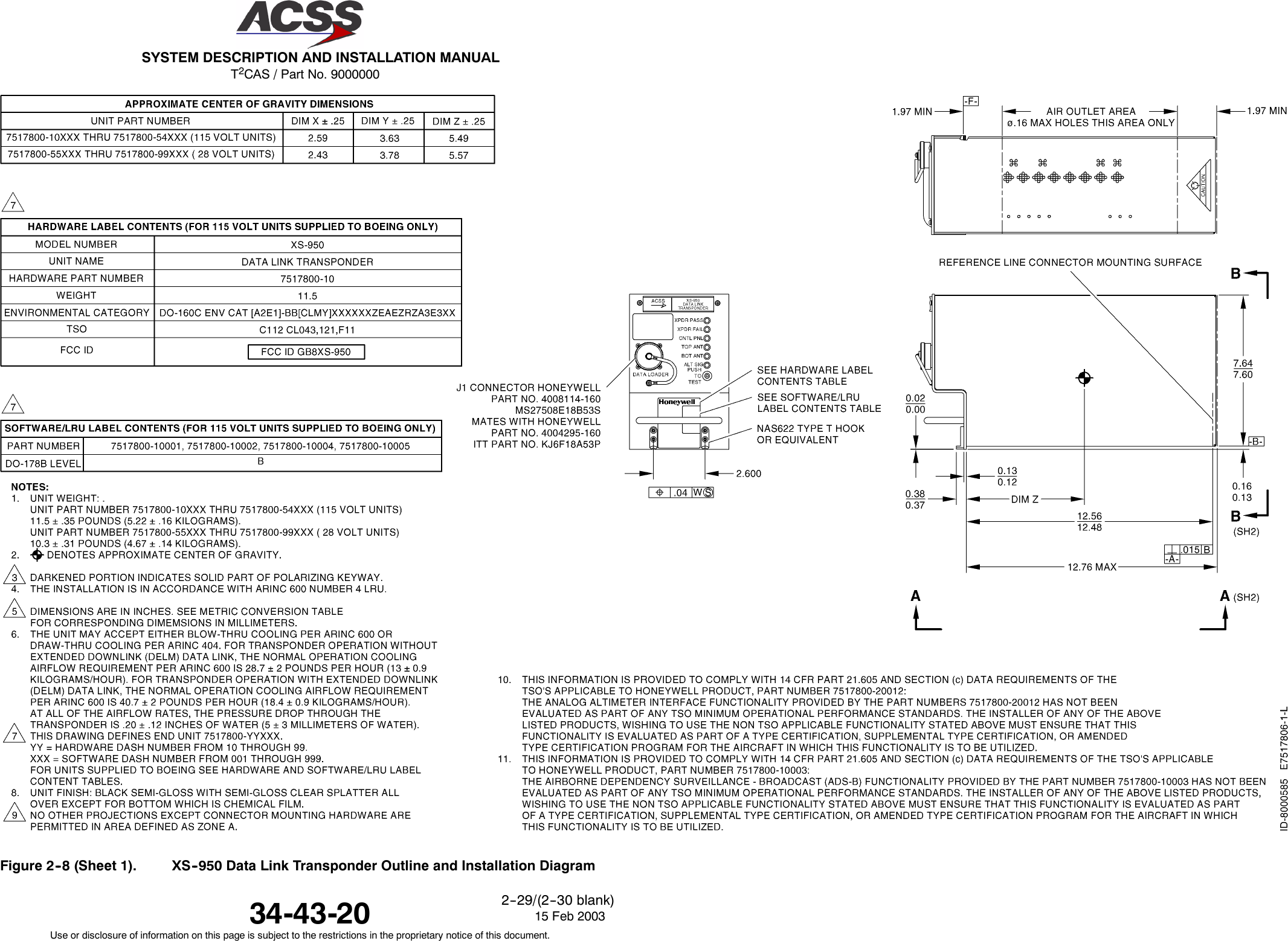
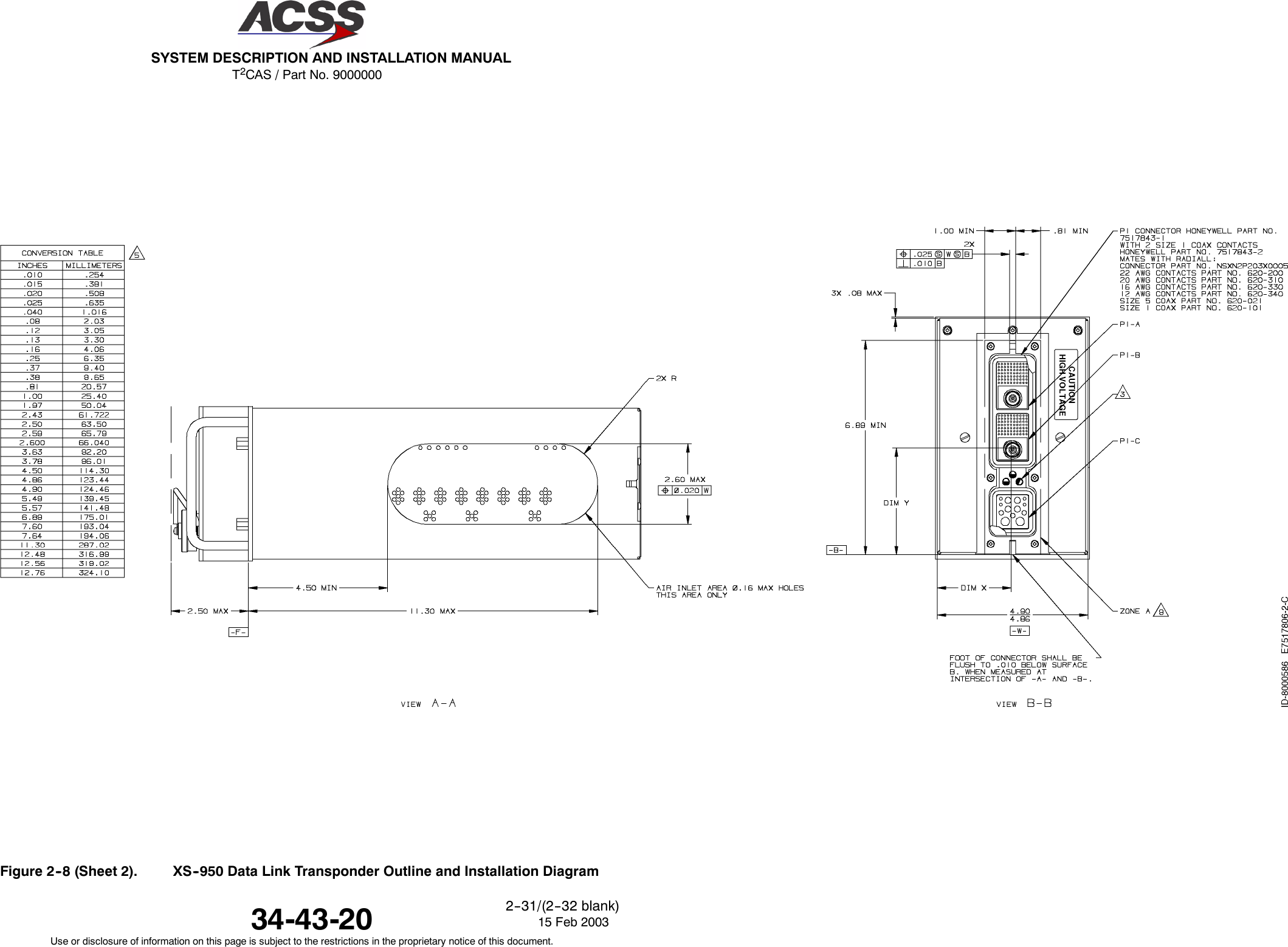
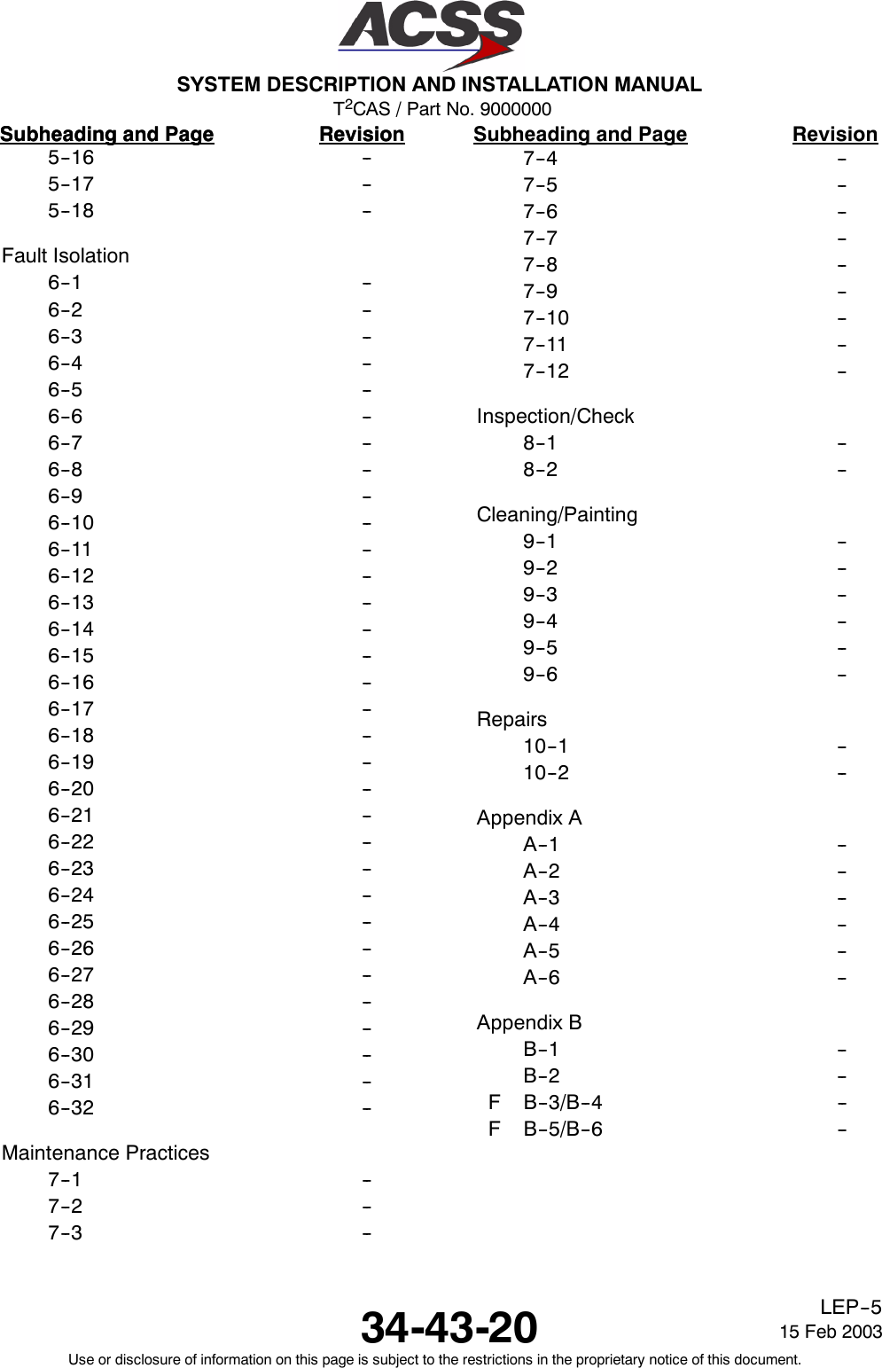
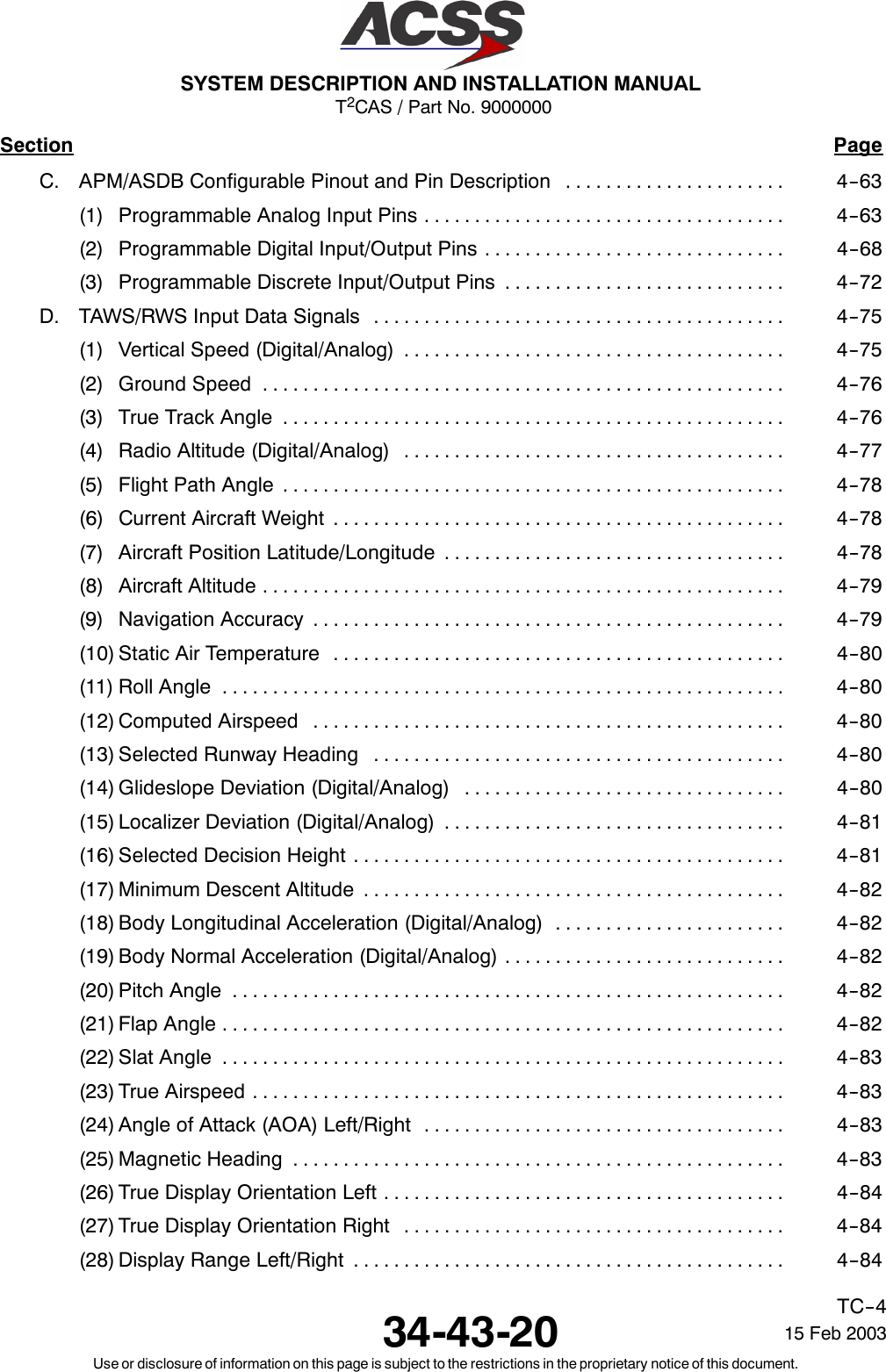
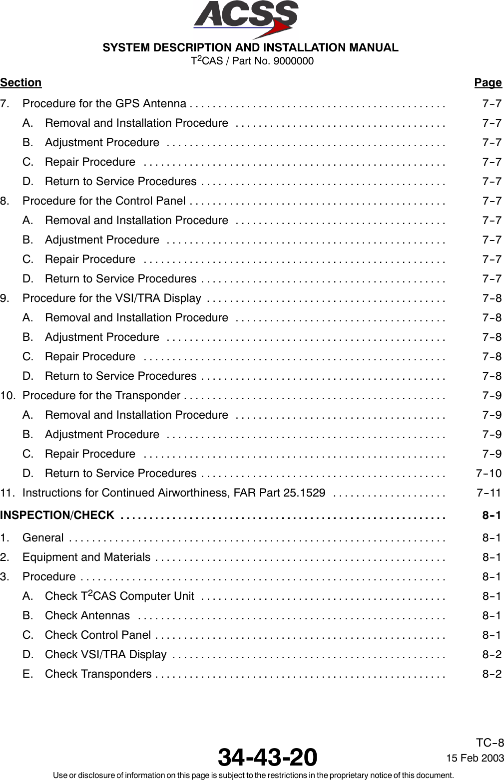
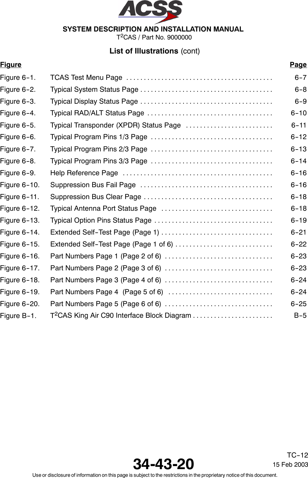
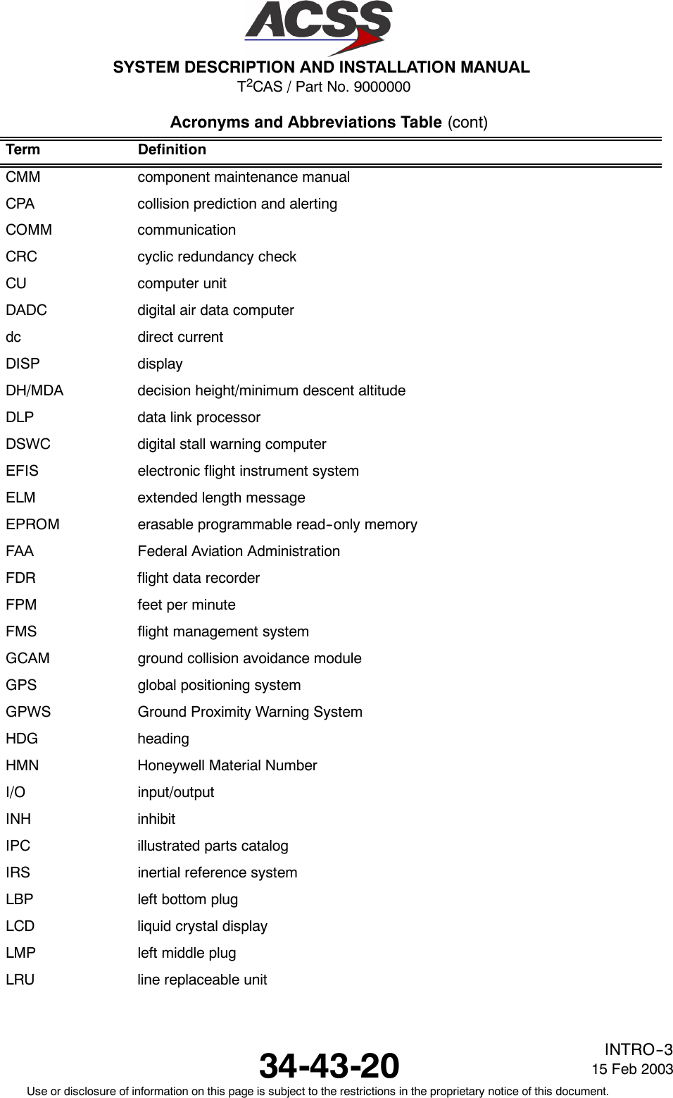
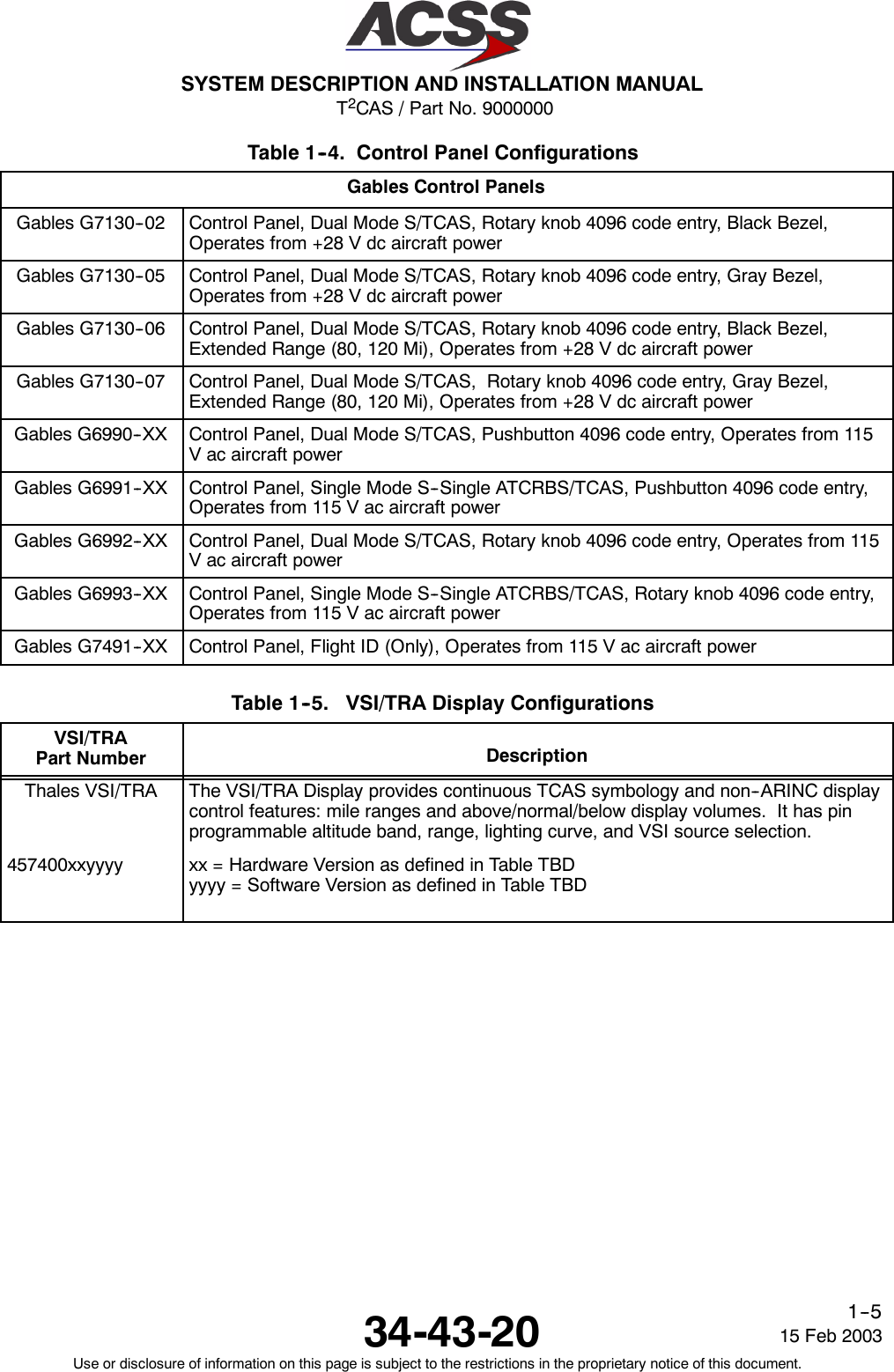
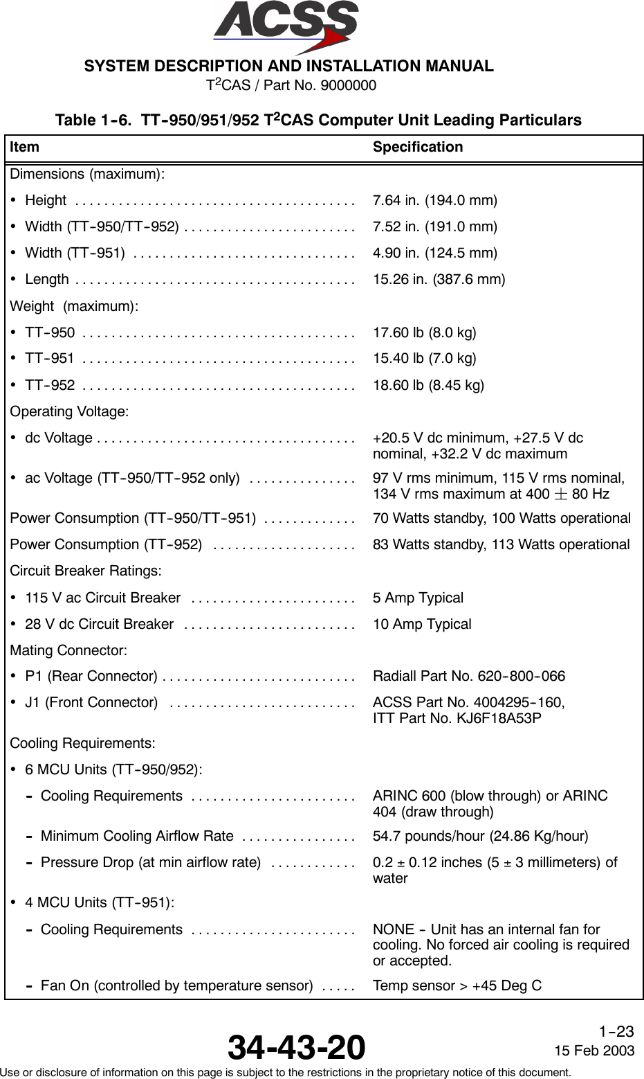
![T2CAS / Part No. 9000000SYSTEM DESCRIPTION AND INSTALLATION MANUAL34-43-2015 Feb 2003Use or disclosure of information on this page is subject to the restrictions in the proprietary notice of this document.1--52Table 1--10. XS--950 Data Link Transponder Leading ParticularsItem SpecificationDimensions (maximum):•Height ...................................... 7.6 in. (192 mm)•Width ...................................... 4.9 in. (124.5 mm)•Length ..................................... 15.2 in. (386 mm)Weight ....................................... 11.5 lb (5.2 kg)Power Requirements (115 V ac version):•OperatingVoltage ............................ 97 to 134 V rms, 115 V rms nominal•Operating Frequency ......................... 320 to 480 Hz, 400 Hz nominal•Power Consumption:-- Standby Mode (No Replies) ................. 40 Watts maximum-- Active mode (Maximum Load) ............... 85 Watts maximum•ExternalCircuitBreakerRating................. 5 A at 115 V ac, 400 HzPower Requirements (28 V dc version):•OperatingVoltage ............................ +18.0 to +32.2 V dc, +27.5 V dc nominal•Power Consumption:-- Standby Mode (No Replies) ................. 40 Watts maximum-- Active mode (Maximum Load) ............... 85 Watts maximum•ExternalCircuitBreakerRating................. 7 A at 28 V dcMating Connector .............................. Radiall Part No. NSXN2P203X0005Mounting ...................................... ARINC 600 4MCU Tray AssemblyTSO .......................................... C112, CL043, 121, F11EnvironmentalSpecifications: .................... DO--160C Environmental Category-- 115Vacversion ........................... [A2E1]--BB[CLMY]XXXXXXZEAEZRZA3E3XX-- 28Vdcversion ........................... [A2E1]--BB[CLMY]XXXXXXZ[BZ]AZZRZA3E3XX•Temperature / Altitude [A2E1]:-- OperatingTemperature ..................... --55 to +70 degrees C-- Ground Survival Temperature ............... --55 to +85 degrees C-- Altitude ................................... Sea Level to 70,000 feet-- LossofCooling ............................ +40 degrees C for 30 minutes minimum](https://usermanual.wiki/ACSS-an-L-3-Communications-and-Thales/TT-950.User-Manual-Part-1/User-Guide-302827-Page-84.png)
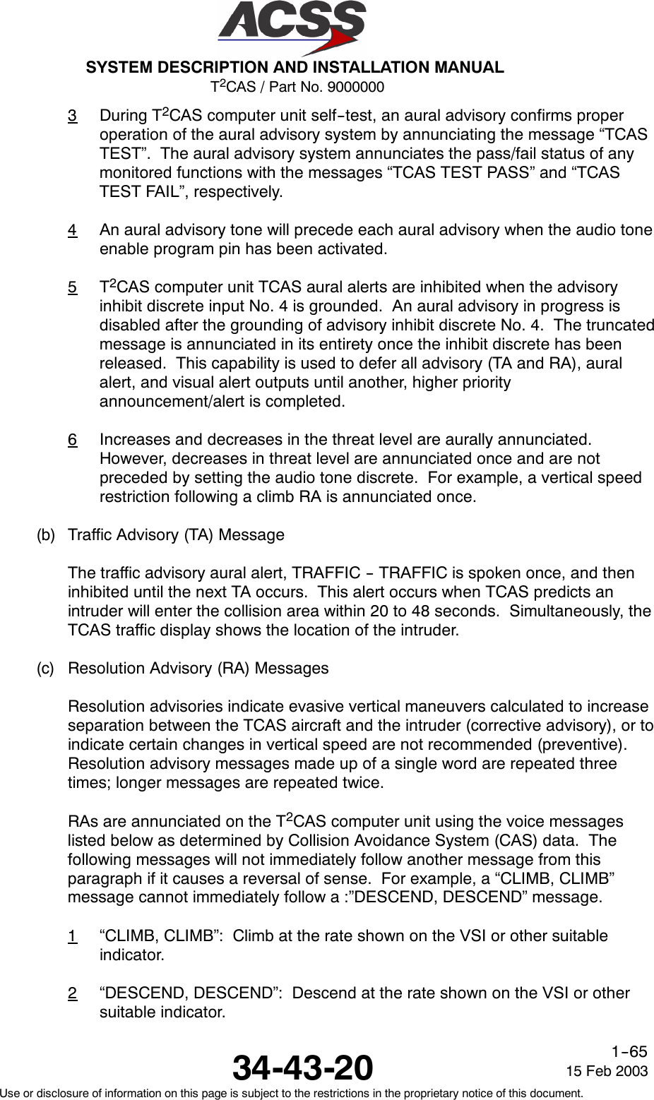
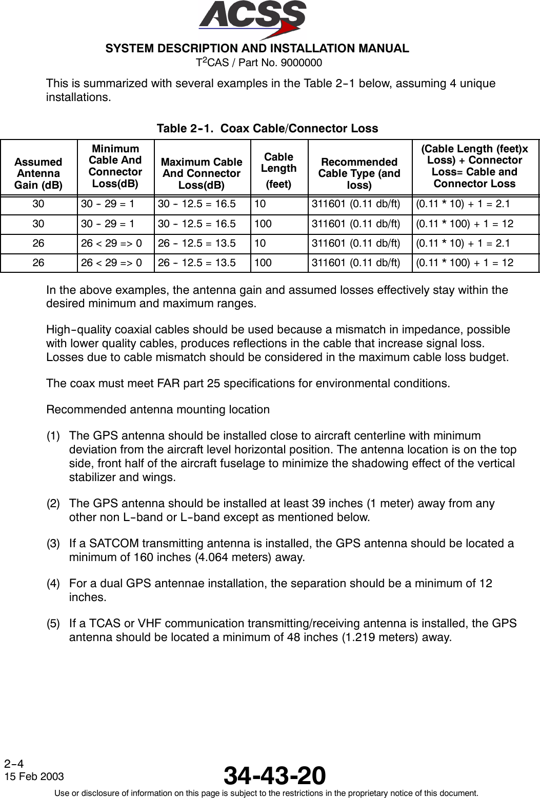
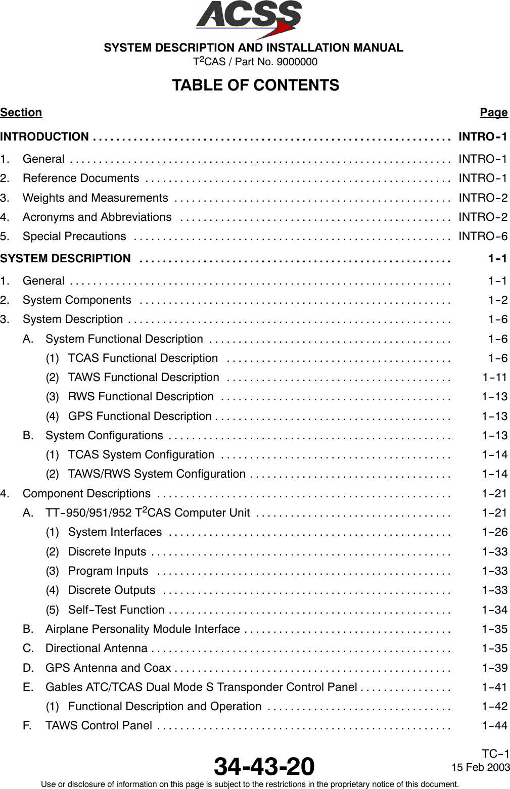
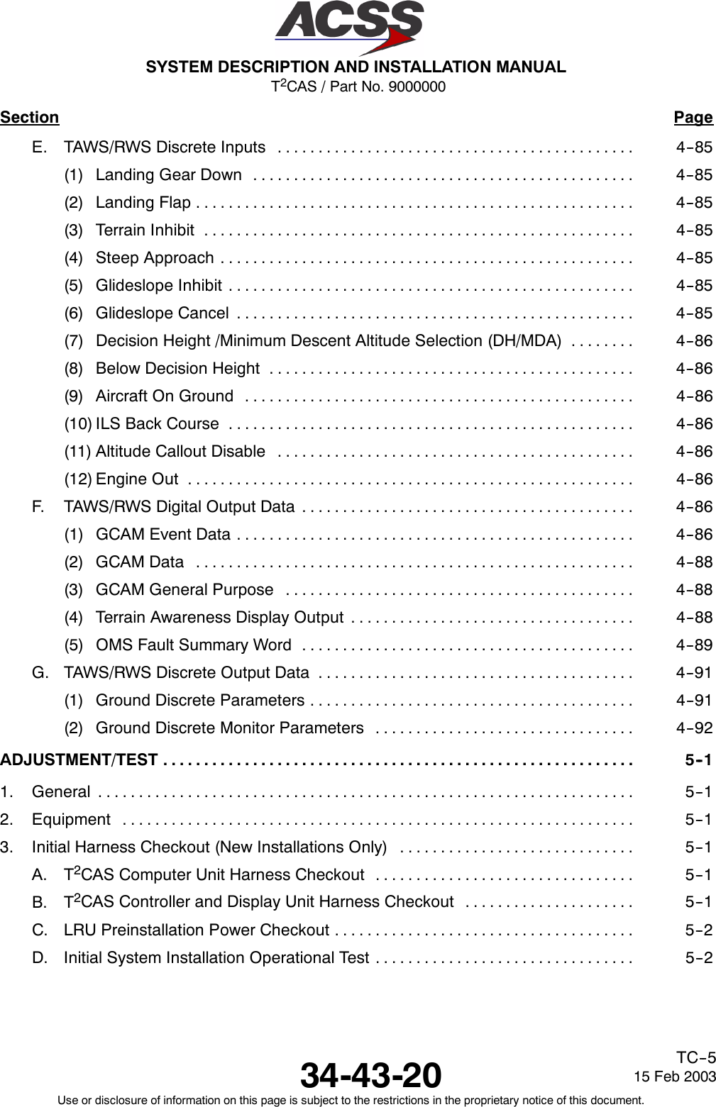
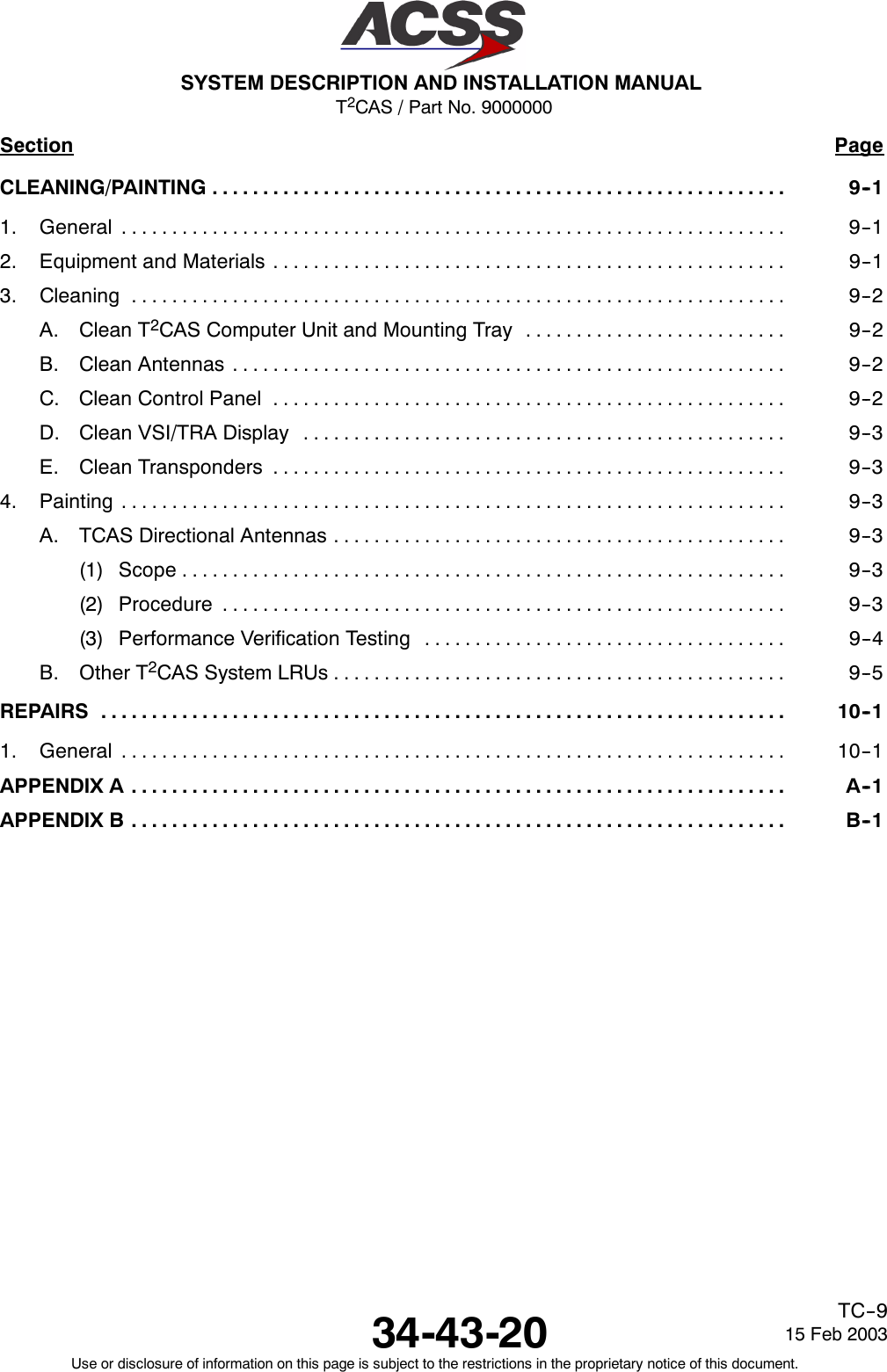
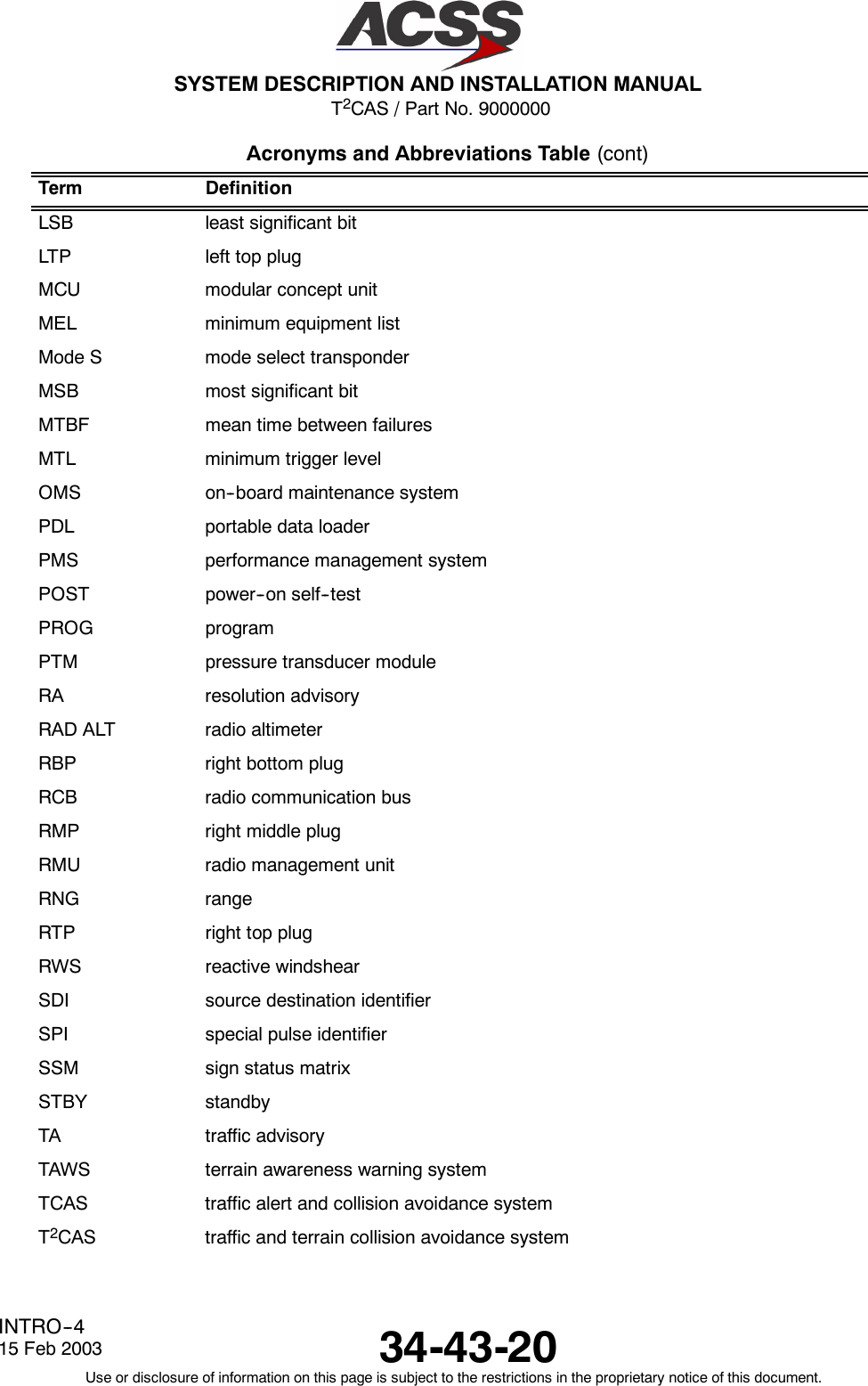
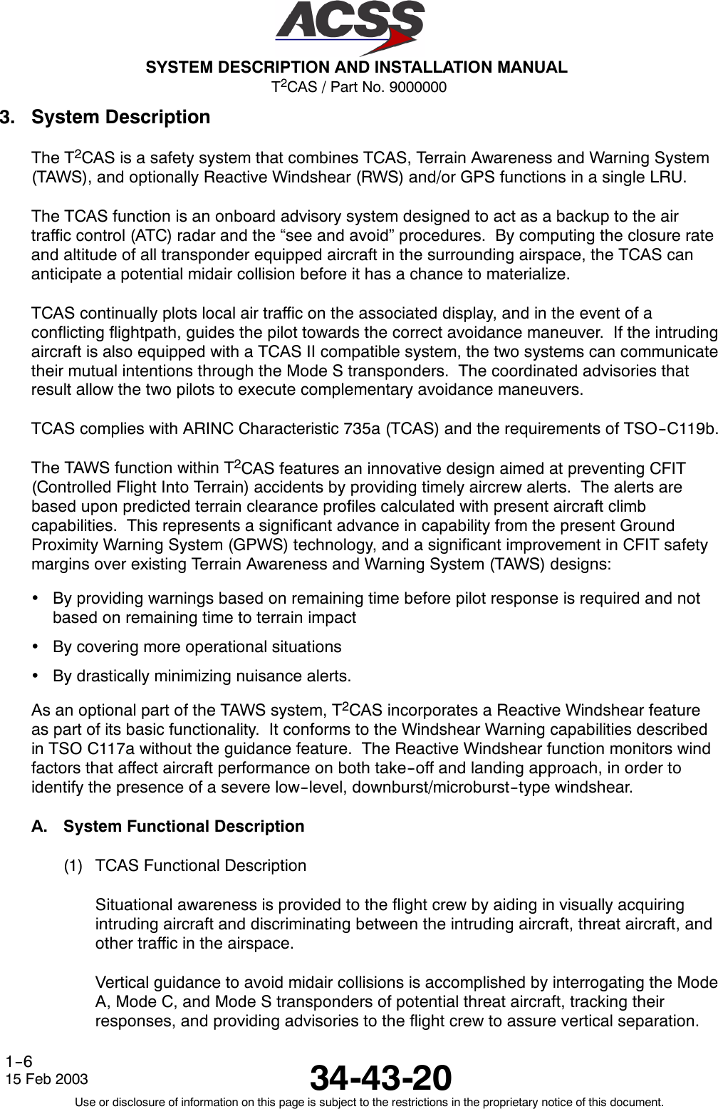
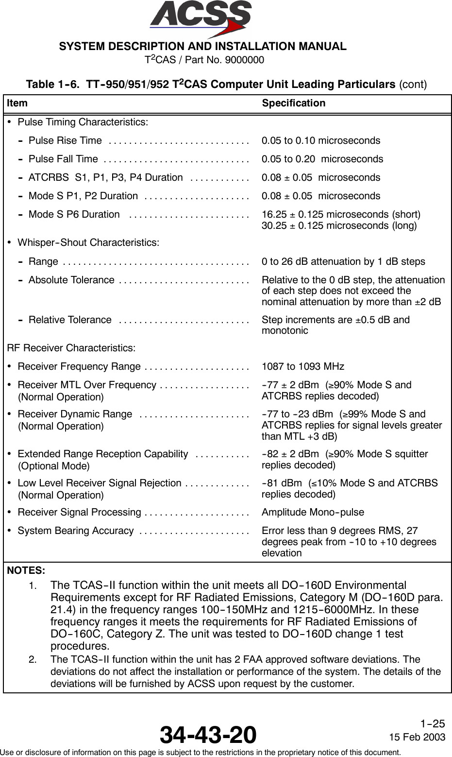
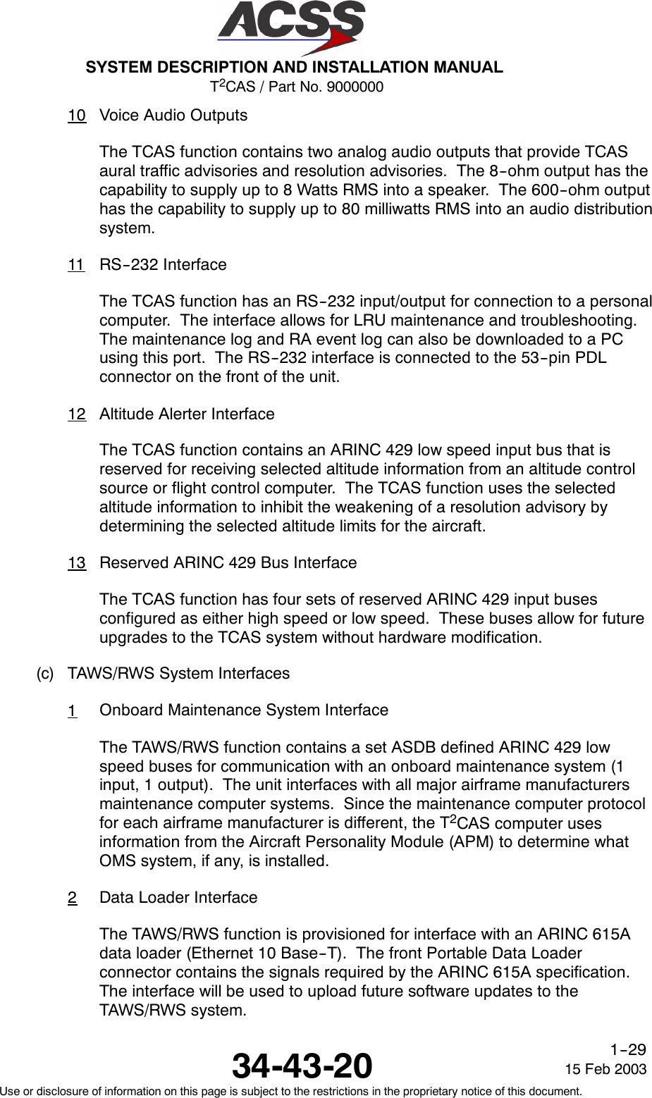
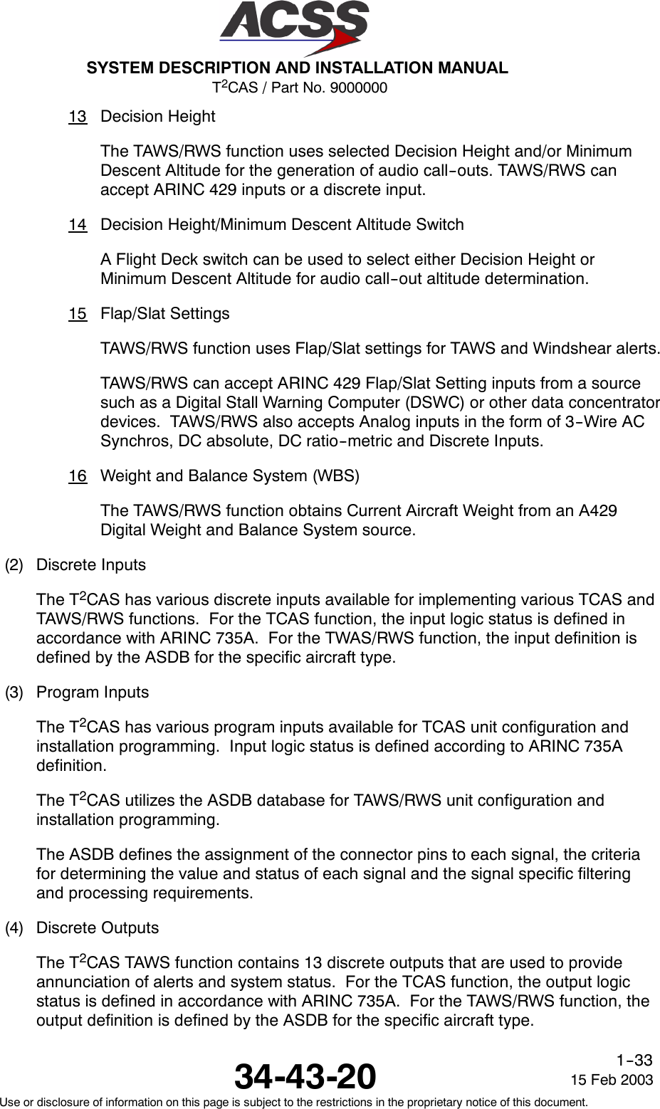
![T2CAS / Part No. 9000000SYSTEM DESCRIPTION AND INSTALLATION MANUAL34-43-20 15 Feb 2003Use or disclosure of information on this page is subject to the restrictions in the proprietary notice of this document.1--53Table 1--10. XS--950 Data Link Transponder Leading Particulars(cont)Item Specification•Vibration [CLMY]:-- Category C ............................... Fixed wing turbojet engine, fuselage mounting-- Category L ............................... Fixed wing reciprocating and turboprop multi andsingle engine over 12,500 pounds, fuselagemounting-- Category M ............................... Fixed wing reciprocating and turboprop multi andsingle engine less than 12,500 pounds, instrumentpanel/console and equipment rack mounting-- Category Y ............................... Helicopter, reciprocating and turbojet, fuselagemountingOperating Modes:•STANDBY................................... Ready but not replying•ATCON .................................... Transponder Modes A and S, no altitude reporting•ATCALT ................................... Transponder Modes A, C, and S. Altitude reportingis enabledTransmitter Frequency ......................... 1090 ±1.0 MHzTransmitterPower ............................. 640 Watts maximum peak pulse, 250 WattsminimumReceiver Frequency ............................ 1030 MHzMinimum Trigger Level (MTL) .................... -- 7 6 ±3dBmMutual Suppression ............................ Bidirectional, accepts +18 to +70 volt pulse input;provides +28 volt nominal outputController Interface:•CircuitConfiguration .......................... Two ARINC 429 control data input ports. 12.5 Kbits/s (low--speed ARINC)•BusProtocol................................. Bus protocol meets requirements defined in ARINC718 for receiving transponder and TCAS controlinformation.TCAS II Interface:•CircuitConfiguration .......................... ARINC 429 input and output bus. 100 K bits/s(high--speed ARINC)•BusProtocol................................. Bus protocol meets requirements defined in ARINC718 and ARINC 735 for standard transponder toTCAS interface](https://usermanual.wiki/ACSS-an-L-3-Communications-and-Thales/TT-950.User-Manual-Part-1/User-Guide-302827-Page-85.png)
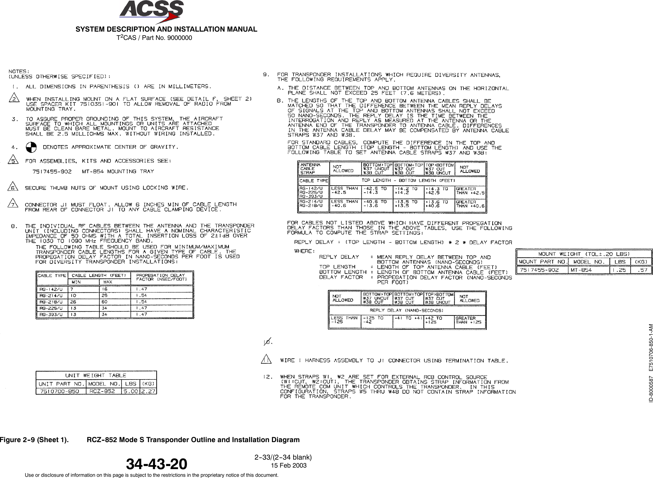
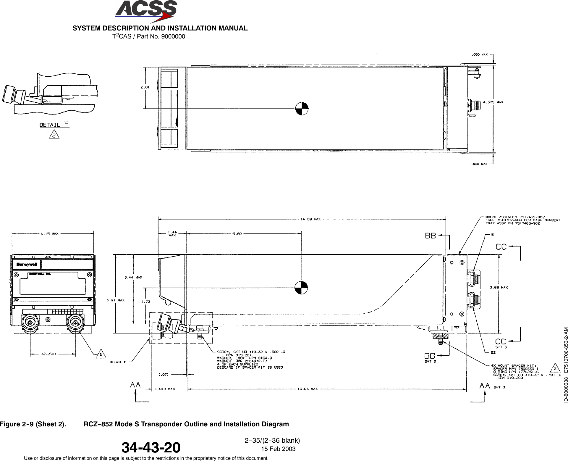
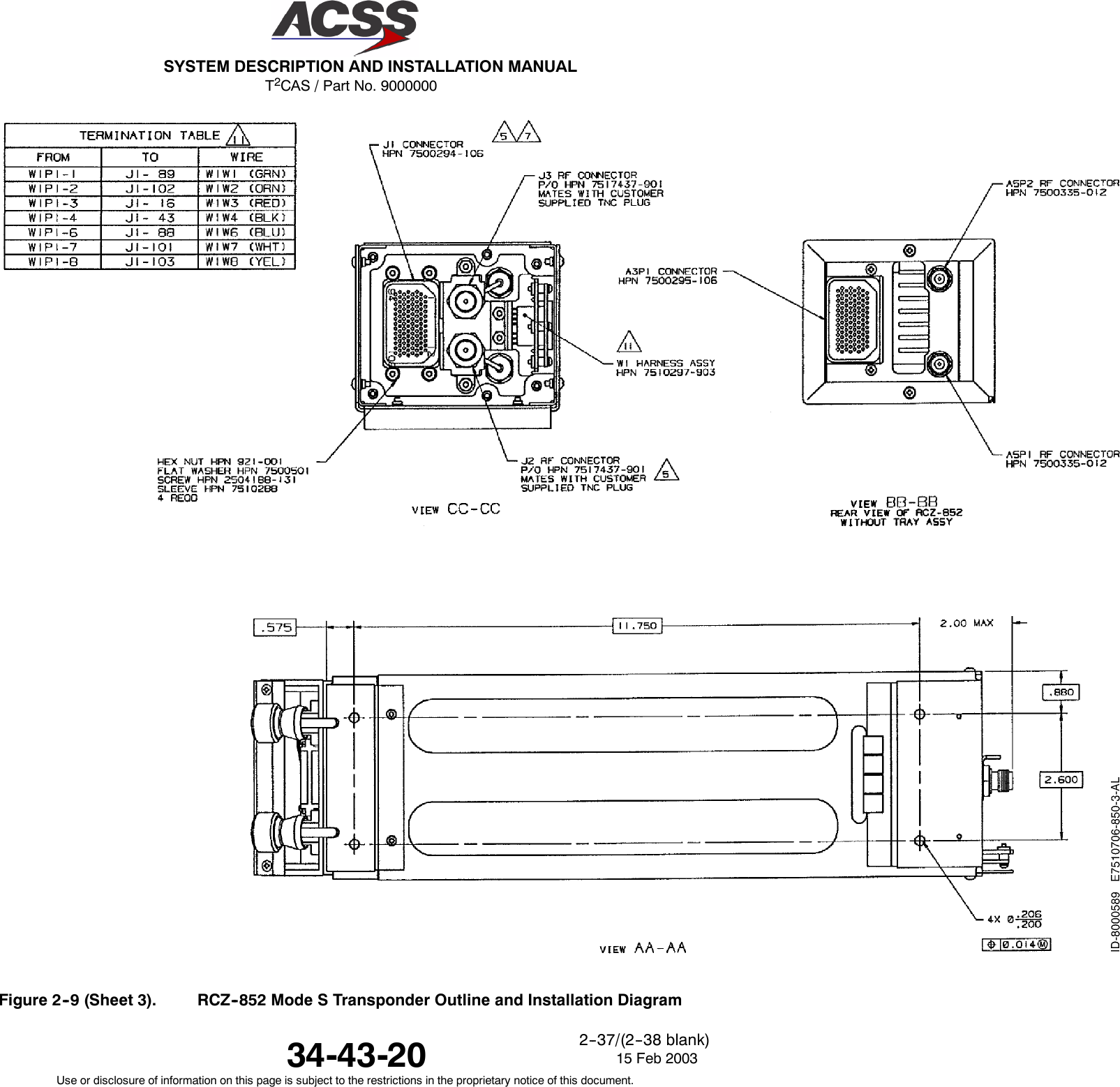
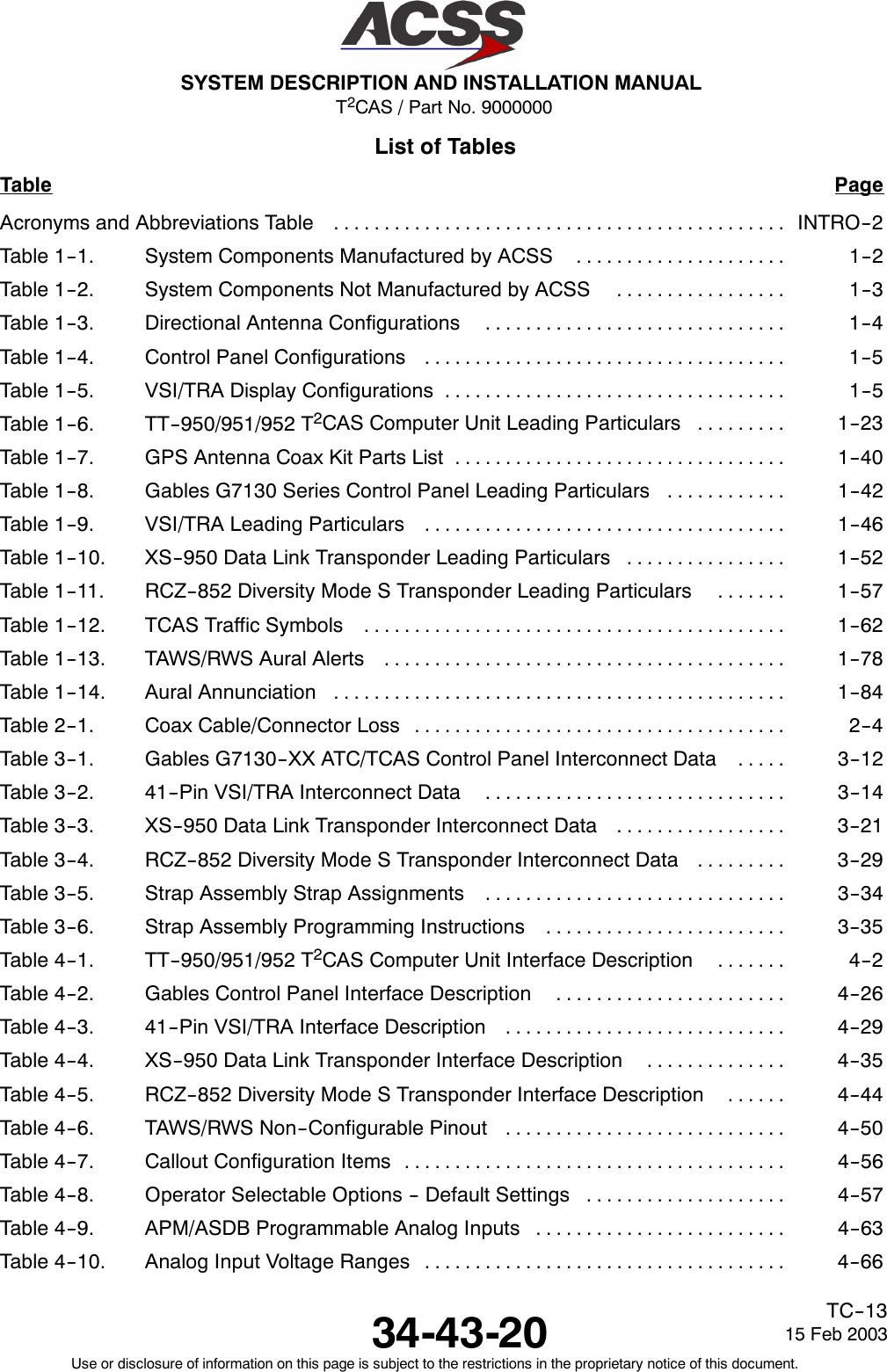
![T2CAS / Part No. 9000000SYSTEM DESCRIPTION AND INSTALLATION MANUAL34-43-20 15 Feb 2003Use or disclosure of information on this page is subject to the restrictions in the proprietary notice of this document.1--57Table 1--11. RCZ--852 Diversity Mode S Transponder Leading ParticularsItem SpecificationDimensions (maximum):•Height ...................................... 3.38 in. (86 mm)•Width ...................................... 4.10 in. (104 mm)•Length ..................................... 14.1 in. (358 mm)Weight ....................................... 5.0 lb (2.27 kg)Power Requirements:•OperatingVoltage ............................ +18.0 to +30.3 V dc, +27.5 V dc nominal•Power Consumption:-- Standby Mode (No Replies) ................. 28 Watts nominal-- Active Mode (Maximum Load) ............... 55 Watts maximum•ExternalCircuitBreakerRating................. 5 A at +27.5 V dcMating Connector .............................. Radiall Part No. NSXN2P203X0005 (Part ofInstallation Kit, ACSS Part No. 7510707--968)Mounting ...................................... Mount Assembly, ACSS Part No. 7517455--902TSO .......................................... C112EnvironmentalSpecifications..................... DO--160B Environmental Category/A2E1/B/JLMY/E1XXXXXZ/BZ/AZZ•Temperature / Altitude [A2E1]:-- OperatingTemperature ..................... --55 to +70 degrees C-- Ground Survival Temperature ............... --55 to +85 degrees C-- Altitude................................... Sea Level to 70,000 feet-- Decompression ............................ 8,000 to 70,000 feet-- Overpressure ............................. --15,000 feet•Vibration [JLMY]:-- Category J ............................... Fixed wing turbojet, subsonic and supersonic,fuselage mounting-- Category L ............................... Fixed wing reciprocating and turboprop multi andsingle engine over 12,500 pounds, fuselagemounting-- Category M ............................... Fixed wing reciprocating and turboprop multi andsingle engine less than 12,500 pounds, instrumentpanel/console and equipment rack mounting-- Category Y ............................... Helicopter, reciprocating and turbojet, fuselagemounting](https://usermanual.wiki/ACSS-an-L-3-Communications-and-Thales/TT-950.User-Manual-Part-1/User-Guide-302827-Page-89.png)