AMBER Wireless AMB2621 Bluetooth Smart Module User Manual UserManual
AMBER Wireless GmbH Bluetooth Smart Module UserManual
UserManual.wiki
>
AMBER Wireless
>
AMB2621 User Manual
UserManual
Navigation menu
Upload a User Manual
Namespaces
Wiki Guide
HTML
PDF
Info
Views
User Manual
Discussion / Help
Navigation
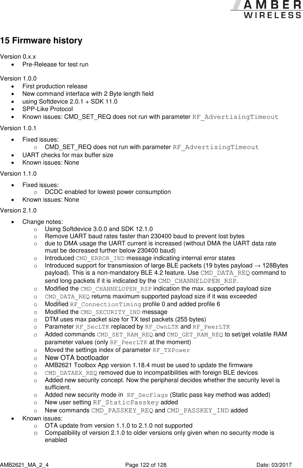
![AMB2621_MA_2_4 Page 5 of 128 Date: 03/2017 Abbreviations and abstract CS Checksum Byte wise XOR combination of the preceding fields BLE Bluetooth Low Energy According to Bluetooth 4.2 specification DTM Direct test mode Mode to test Bluetooth specific RF settings LPM Low power mode Mode for efficient power consumption RF Radio frequency Describes wireless transmission MAC MAC Address of the module BTMAC Bluetooth conform MAC Address of the module used on the RF-interface Payload The intended message in a frame/package RSSI Receive Signal Strength Indicator The RSSI indicates the strength of the RF signal. Its value is always printed in two’s complement notation. Soft device Operating system used by the nRF52 chip User settings Settings to configure the module. Any relation to a specific entry in the user settings is marked in a special font and can be found in chapter 9. UART Universal Asynchronous Receiver Transmitter Allows the serial communication with the module. Hexadecimal [HEX] 0xhh All numbers beginning with 0x are hexadecimal numbers. All other numbers are decimal, unless stated otherwise. I/O Input/output Pinout description](https://usermanual.wiki/AMBER-Wireless/AMB2621/User-Guide-3370134-Page-5.png)
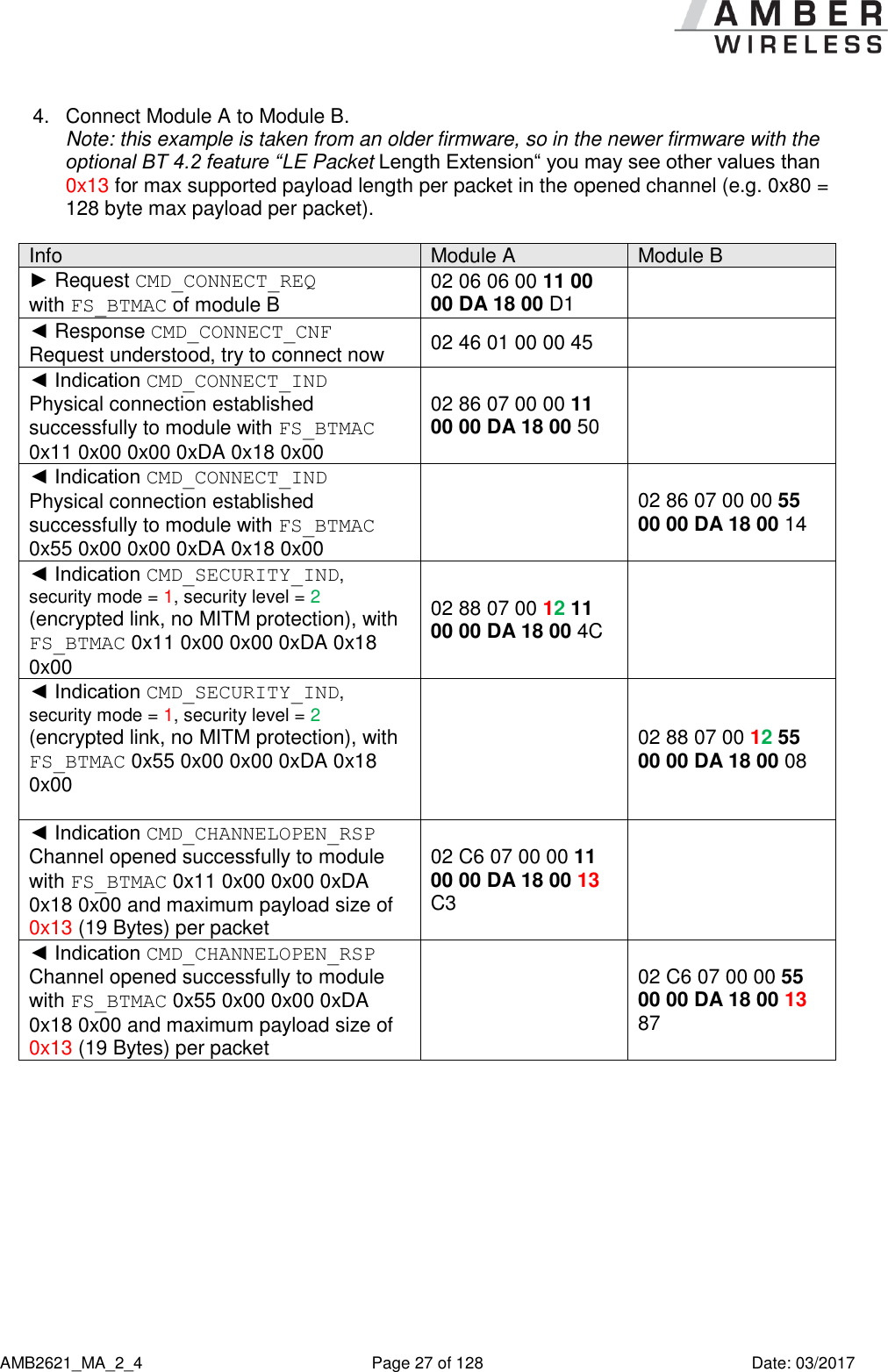

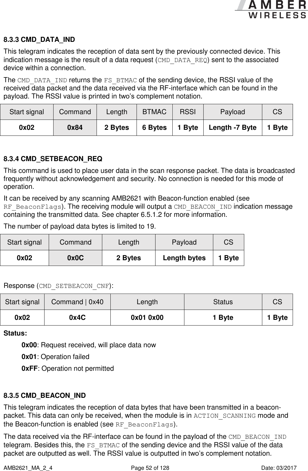
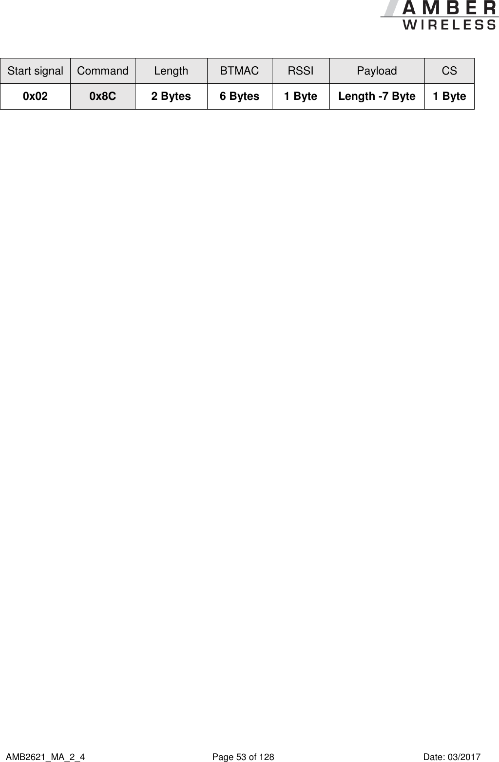
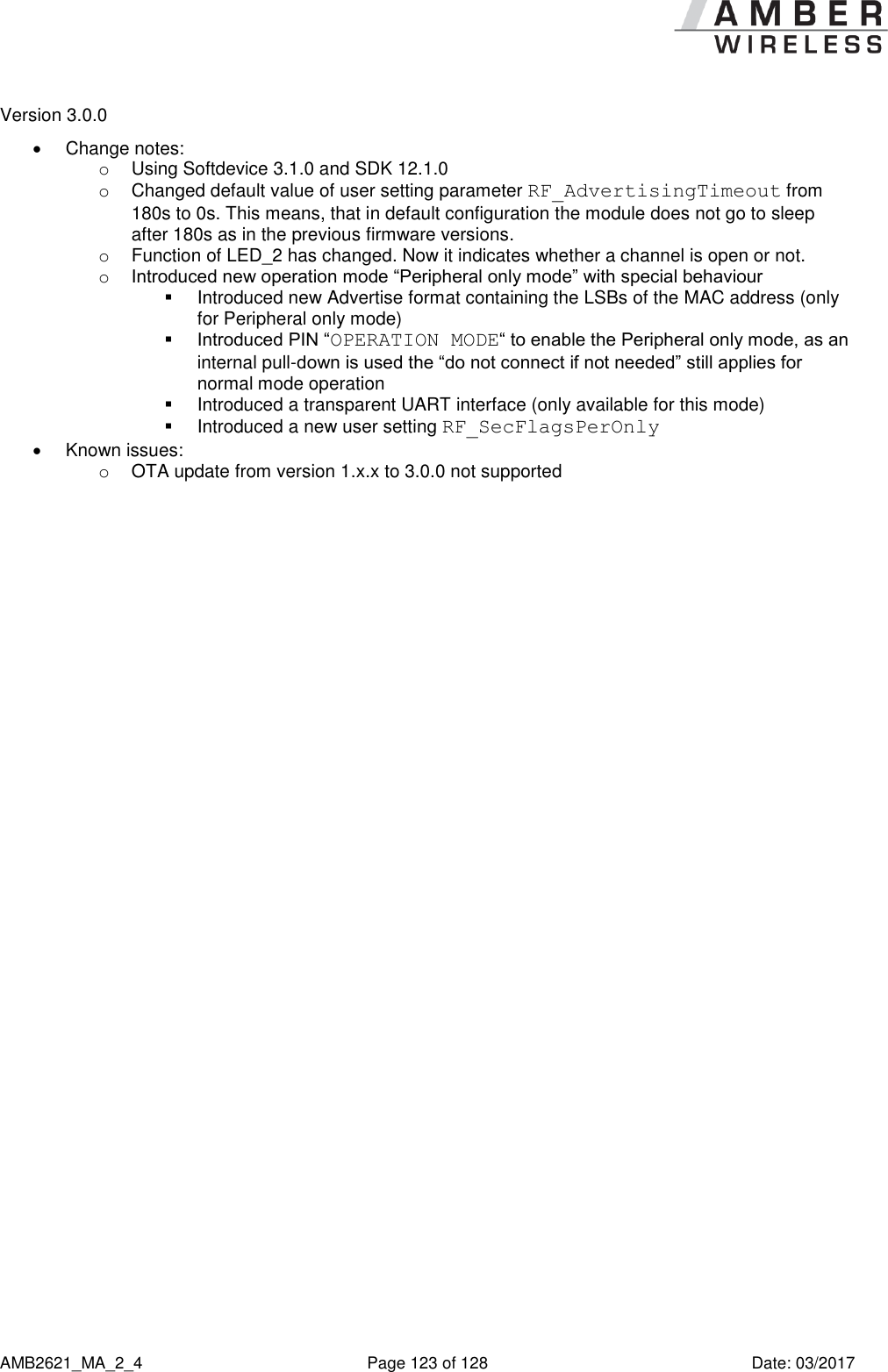
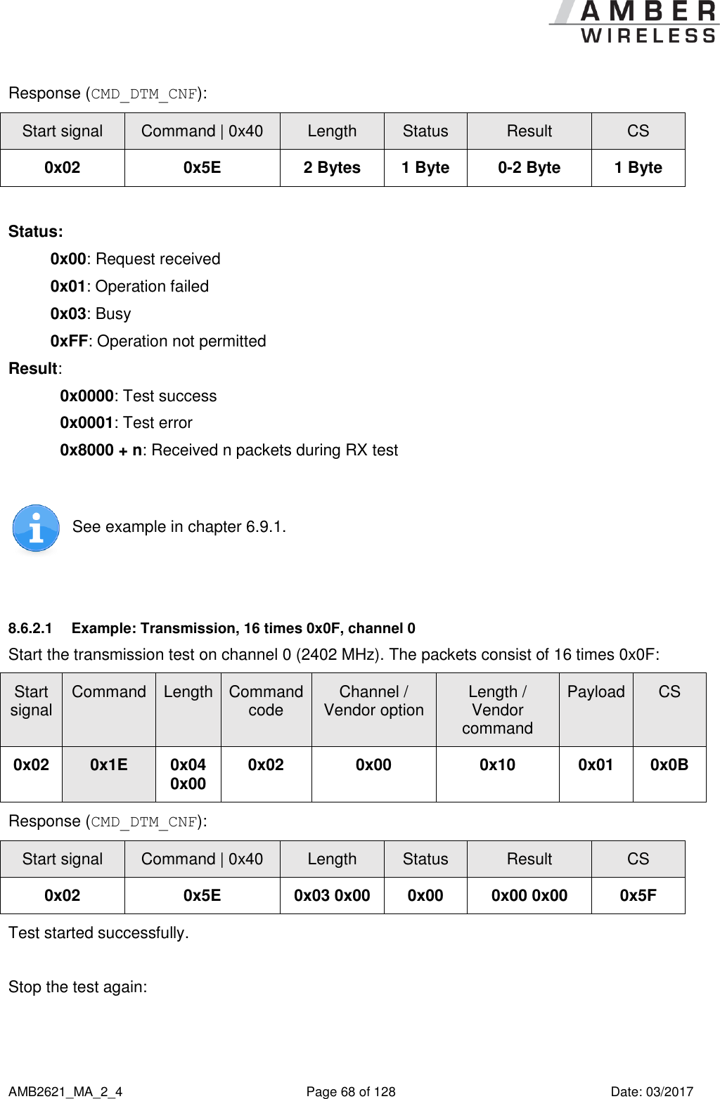
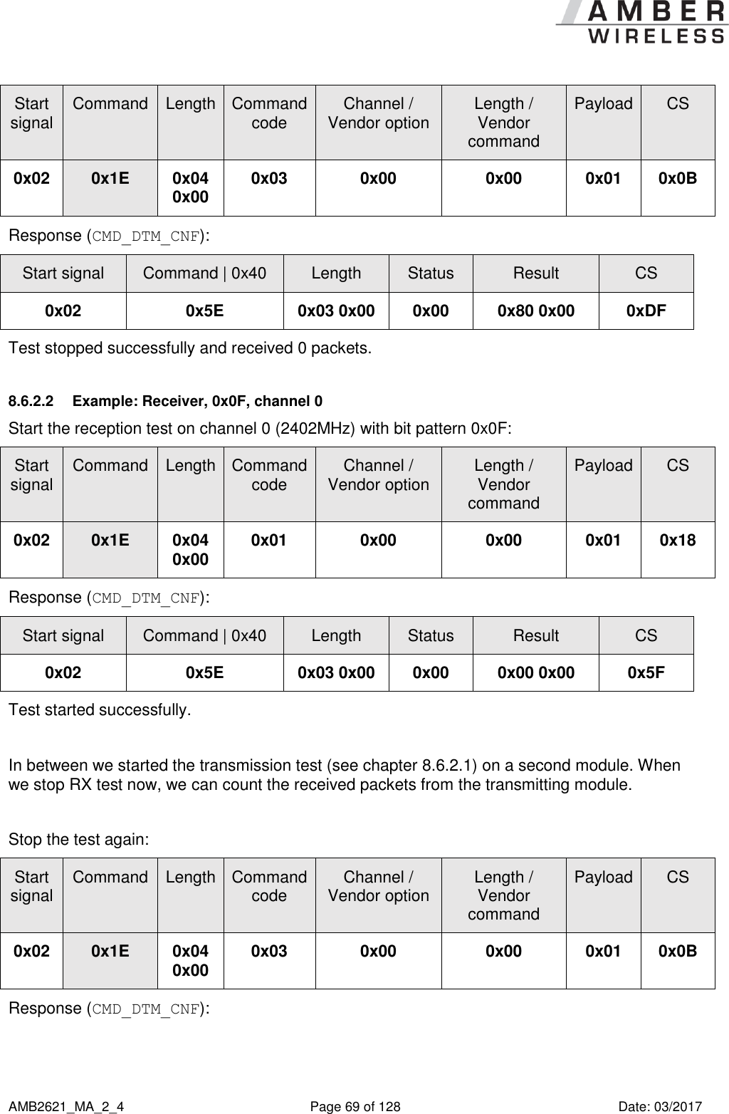
![AMB2621_MA_2_4 Page 67 of 128 Date: 03/2017 Format: Start signal Command Length Command code Channel / Vendor option Length / Vendor command Payload CS 0x02 0x1E 0x04 0x00 1 Byte 1 Byte 1 Byte 1 Byte 1 Byte Command code: 0x00: DTM reset (note: this command does not perform a module reset. 0x01: Start RX test 0x02: Start TX test 0x03: Stop last test Payload: 0x00: Bit pattern PRBS9 0x01: Bit pattern 0x0F 0x02: Bit pattern 0x55 0x03: Vendor specific Payload ≠ Vendor specific (0x00, 0x01 or 0x02) Payload = Vendor specific (0x03) Length / Vendor Command: Length of the packet to send Length / Vendor Command: 0x00: Carrier test 0x02: Set transmission power Channel: Frequency = (2402 + Channel * 2) MHz to be used for RX/TX Vendor option: (dependant on used “Vendor command”) Frequency = (2402 + [Vendor option] * 2) MHz or [Vendor option] := TXPower (in two’s complement notation) in steps of 4dB](https://usermanual.wiki/AMBER-Wireless/AMB2621/User-Guide-3370134-Page-67.png)
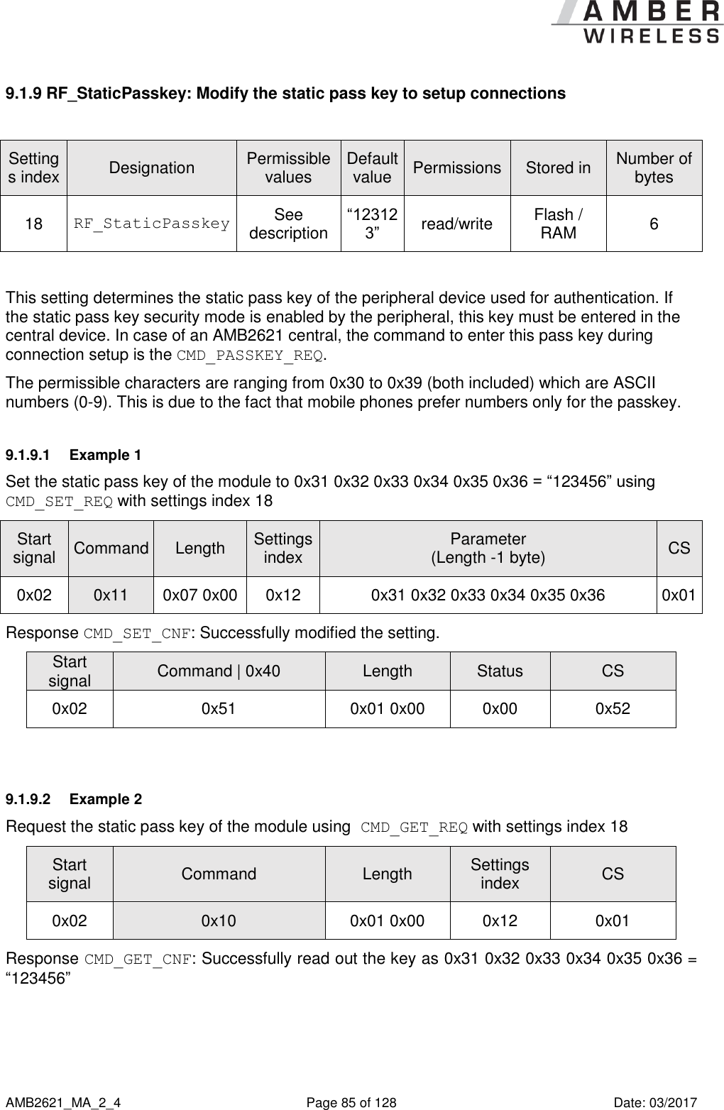
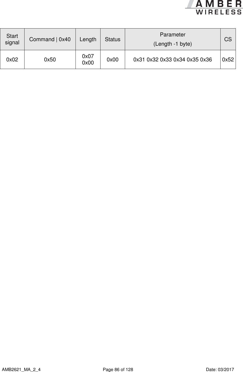
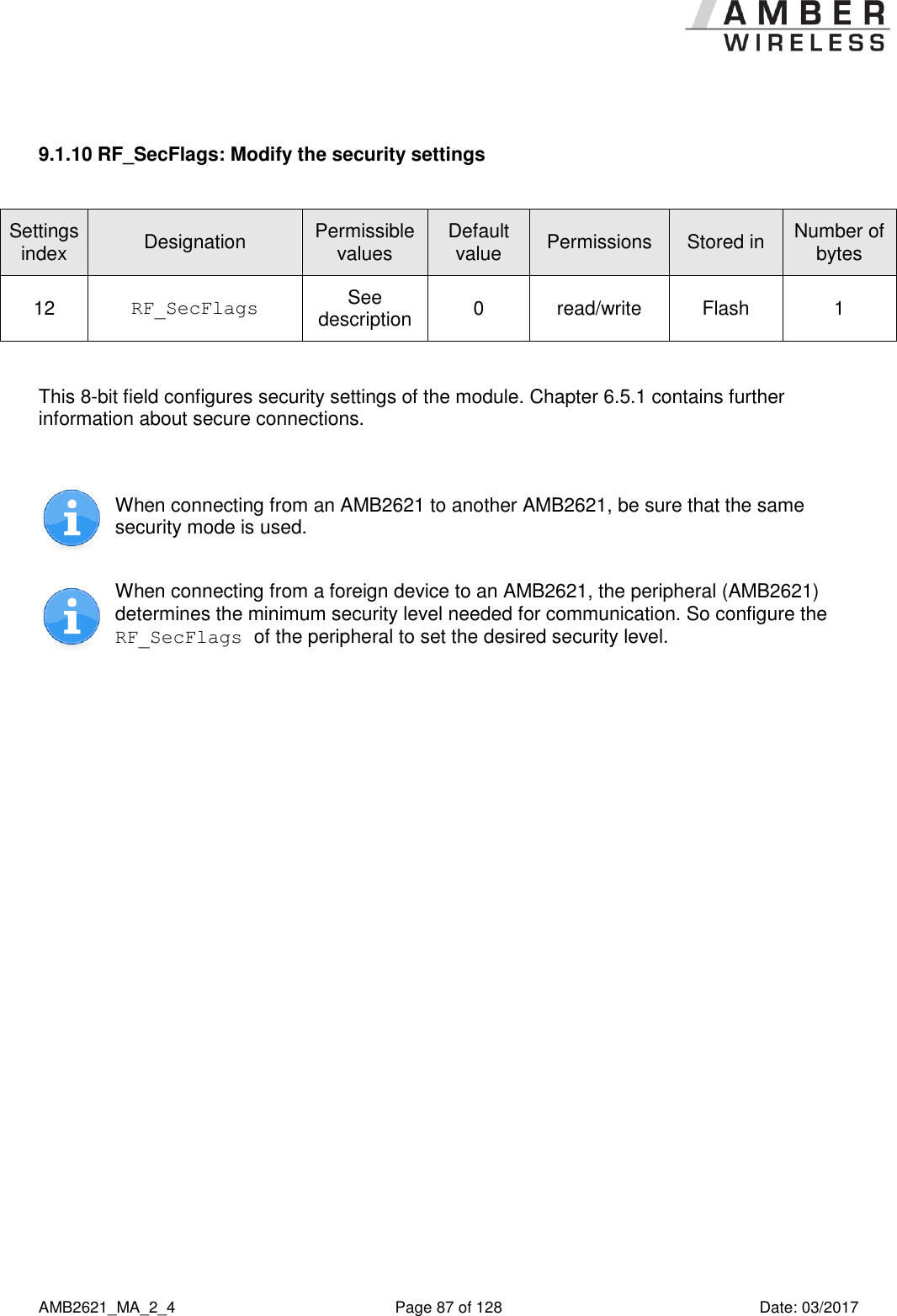
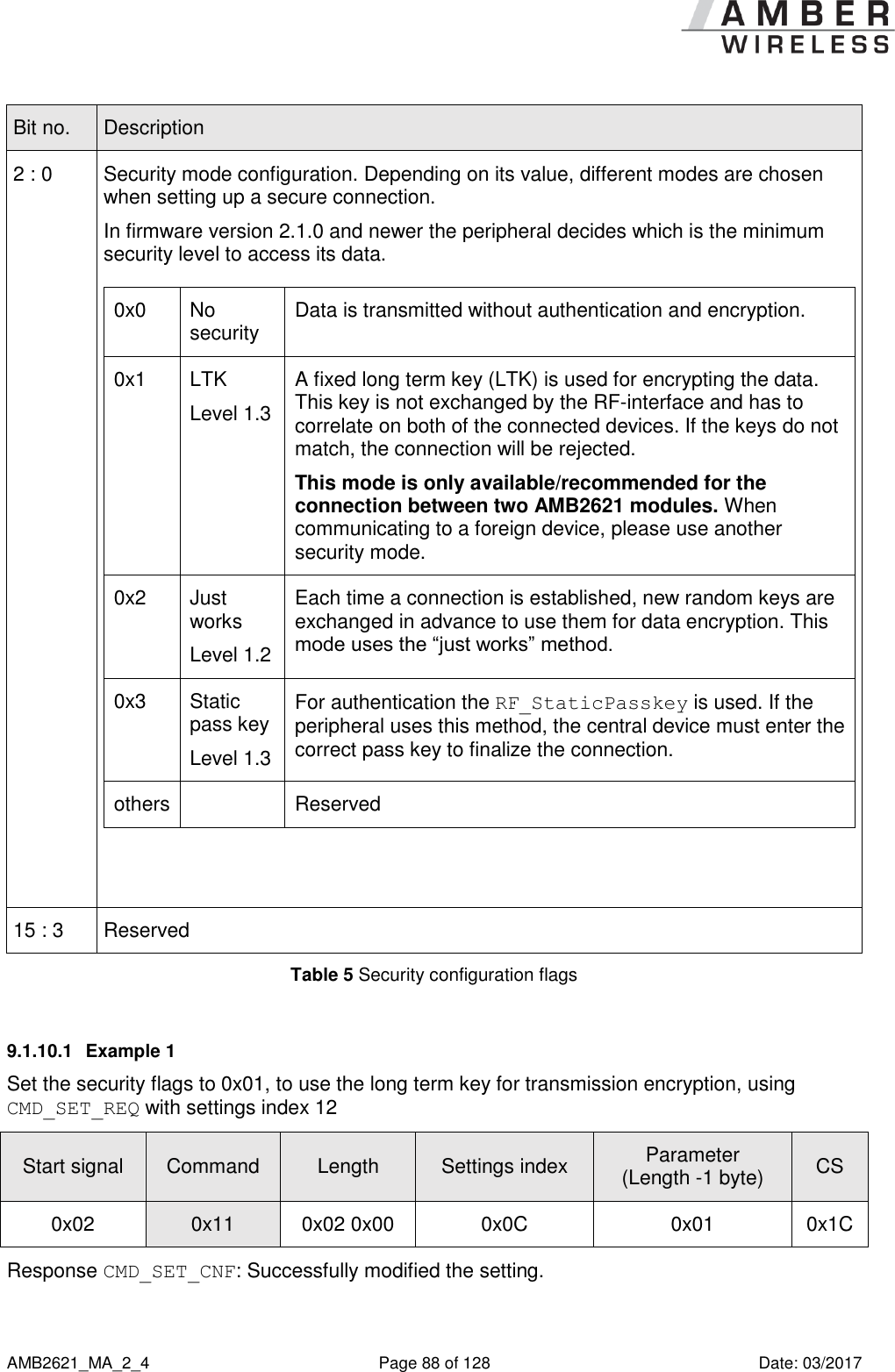
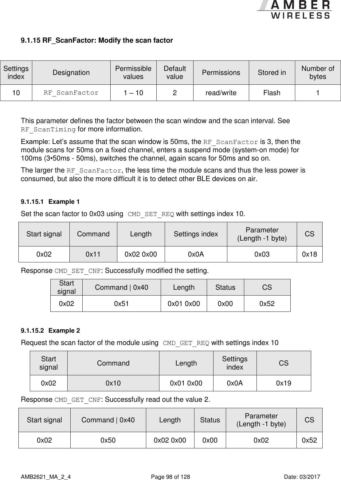
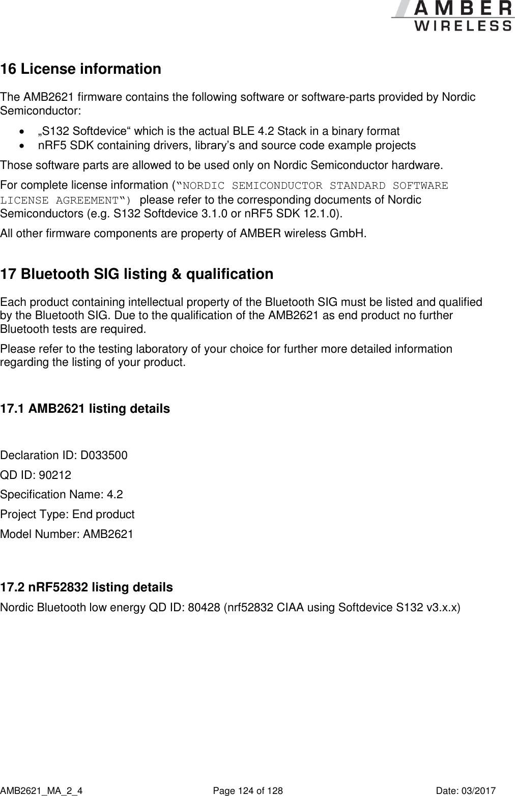
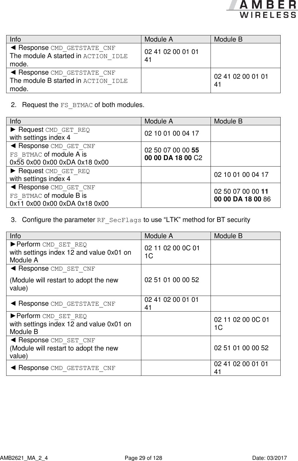
![AMB2621_MA_2_4 Page 99 of 128 Date: 03/2017 9.1.16 RF_ScanTiming: Modify the scan timing settings Settings index Designation Permissible values Default value Permissions Stored in Number of bytes 9 RF_ScanTiming 0 – 5 1 read/write Flash 1 The RF_ScanTiming enables the possibility to configure the timing behaviour of the module’s RF interface during advertising and scanning state. Using this parameter several predefined configurations can be chosen, which include timing parameters, such as the frequency of advertising packets and the length of a scan window. The choice of the RF_ScanTiming primarily affects the latency of device detection on air as well as the current consumption. The lower the RF_ScanTiming, the faster the modules can find each other for communication, but also the more power will be consumed. RF_ScanTiming 0 1 2 3* 4* 5* Advertising interval [ms] 20 40 250 1000 5000 10240 Scan window [ms] 25 50 312 1250 6250 10240 Scan interval [ms] Defined by the RF_ScanFactor. Connection setup timeout [s] 1 2 2 5 20 35 Current consumption *Mainly suitable for transmitting data using Beacons without consuming much energy. Further information: In ACTION_SCANNING mode, the scan interval defines the time after which the module switches channel to detect other BLE devices in range. See also RF_ScanFactor. In ACTION_SCANNING mode, the scan window defines the section of the scan interval, where the module is scanning. During the remaining time, the module enters a suspend mode (system-on mode). See also RF_ScanFactor.](https://usermanual.wiki/AMBER-Wireless/AMB2621/User-Guide-3370134-Page-99.png)
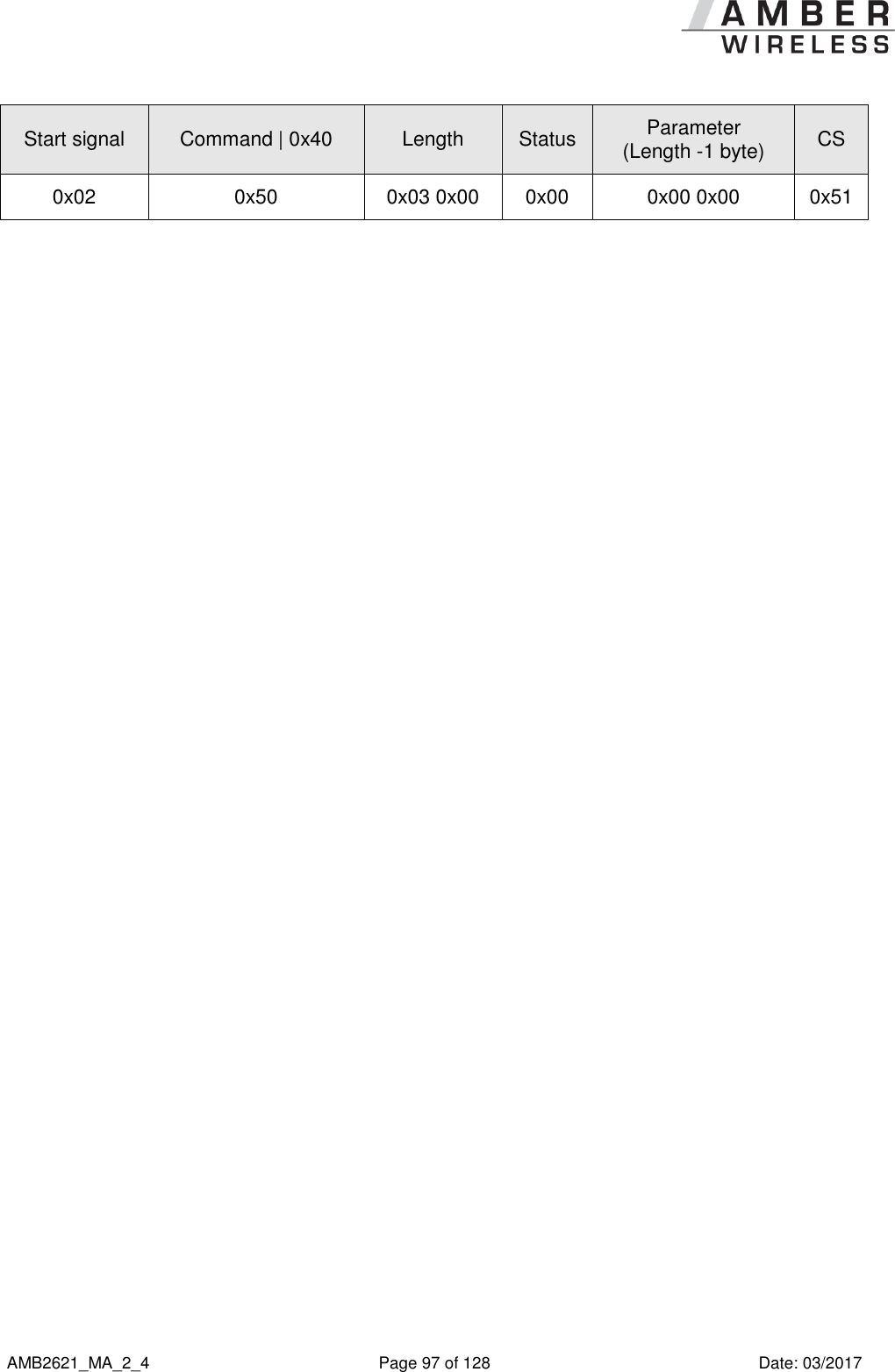
![AMB2621_MA_2_4 Page 100 of 128 Date: 03/2017 In ACTION_IDLE mode, the advertising interval defines the time after which the module periodically sends its advertising packet. In between, the module enters a suspend mode (system-on mode). The connection setup timeout defines the time after which a connection request has to be answered by the peripheral. Please ensure that all members of a network support the same advertising and scan timing parameters. To ensure that the module is allowed to send a sufficient amount of advertising packets, please also check the RF_AdvertisingTimeout parameter. To connect to an Android or iOS device, please first review their supported settings [1]. 9.1.16.1 Example 1 Set the scan timing parameter to 0x00 using CMD_SET_REQ with settings index 9. Start signal Command Length Settings index Parameter CS 0x02 0x11 0x02 0x00 0x09 0x00 0x18 Response CMD_SET_CNF: Successfully modified the setting. Start signal Command | 0x40 Length Status CS 0x02 0x51 0x01 0x00 0x00 0x52 9.1.16.2 Example 2 Request the scan timing parameter of the module using CMD_GET_REQ with settings index 9 Start signal Command Length Settings index CS 0x02 0x10 0x01 0x00 0x09 0x1A Response CMD_GET_CNF: Successfully read out the value 4. Start signal Command | 0x40 Length Status Parameter (Length -1 byte) CS 0x02 0x50 0x02 0x00 0x00 0x04 0x54](https://usermanual.wiki/AMBER-Wireless/AMB2621/User-Guide-3370134-Page-100.png)
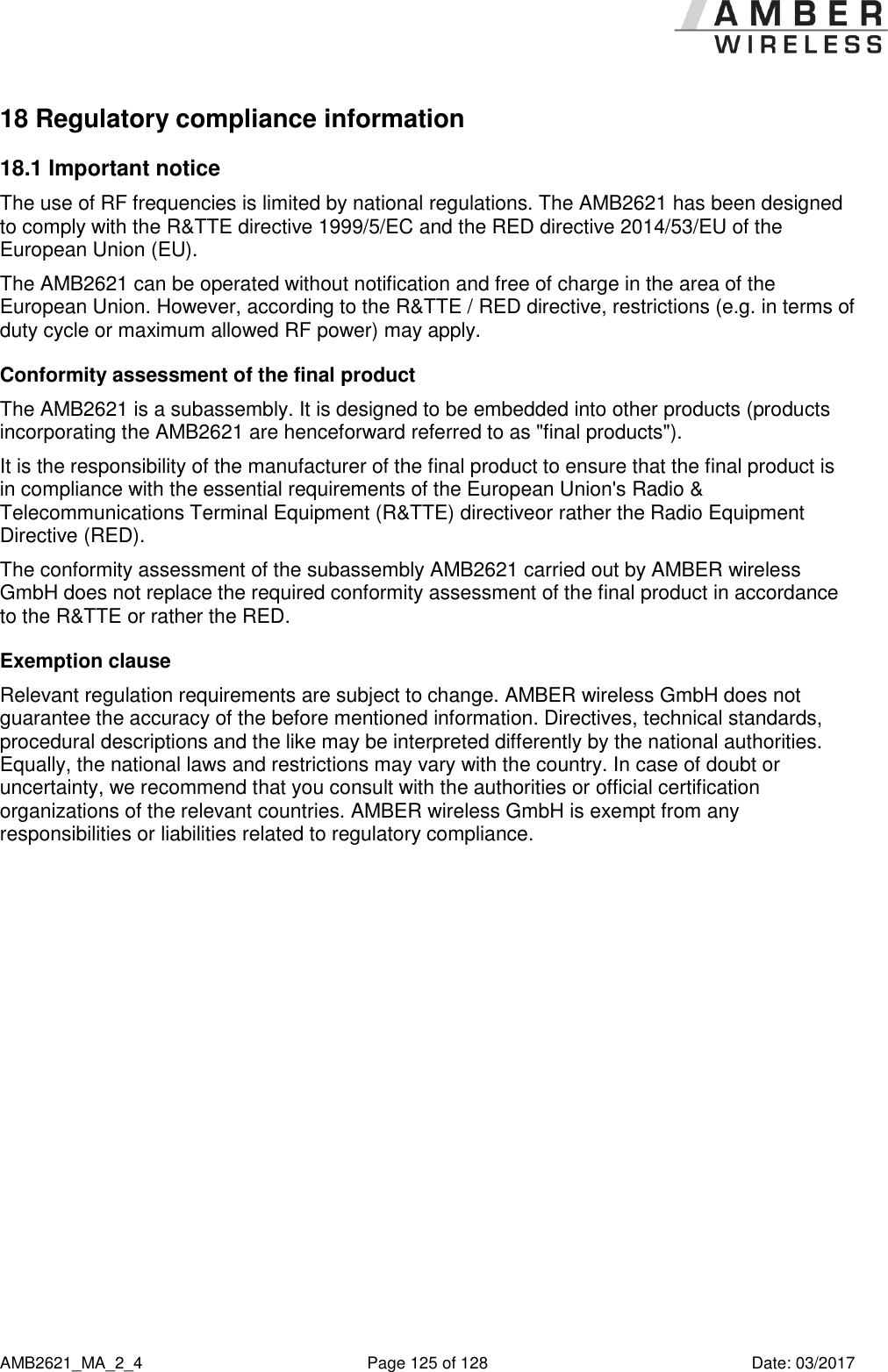
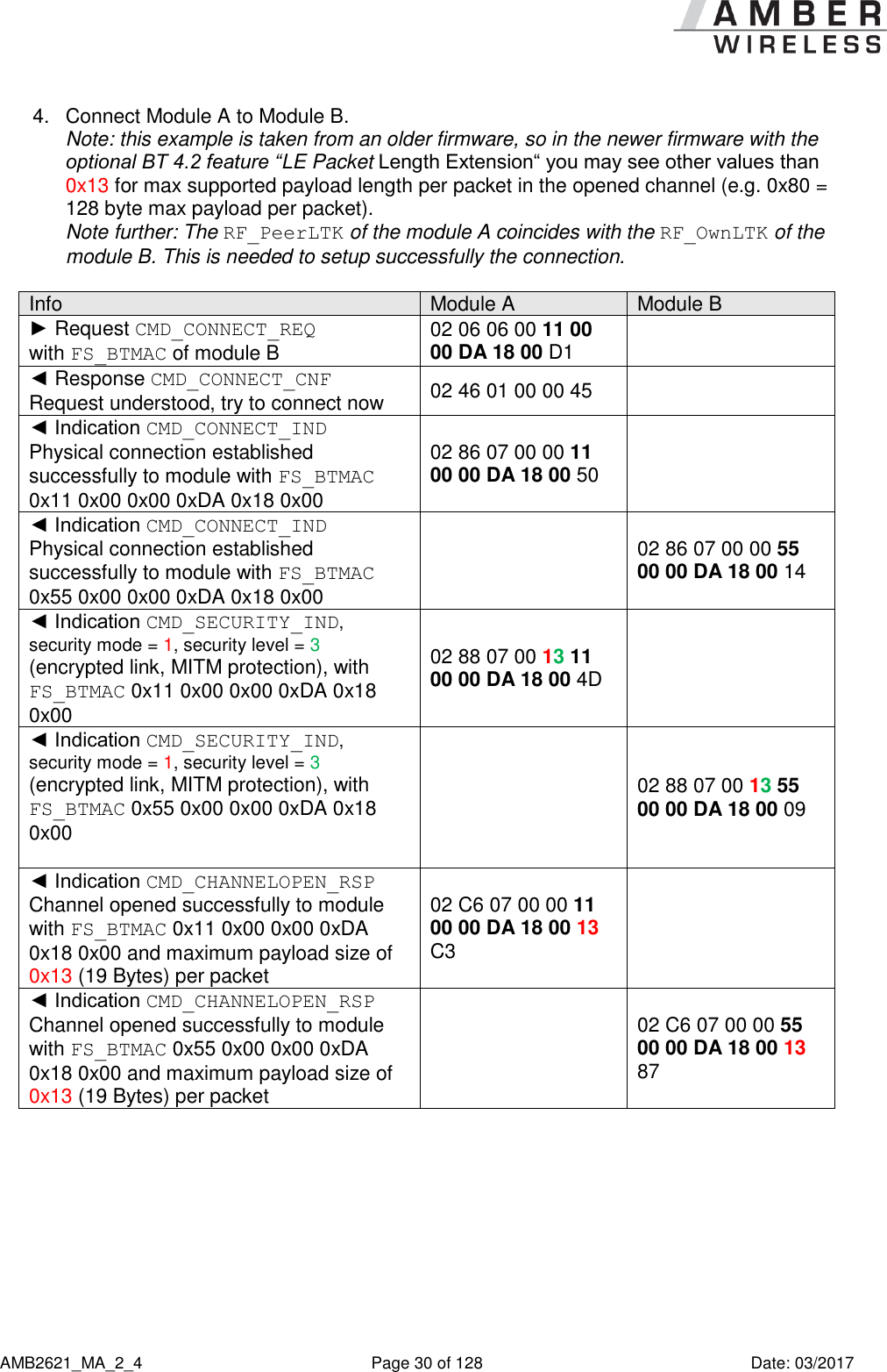
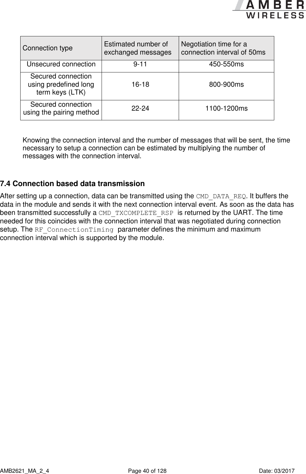
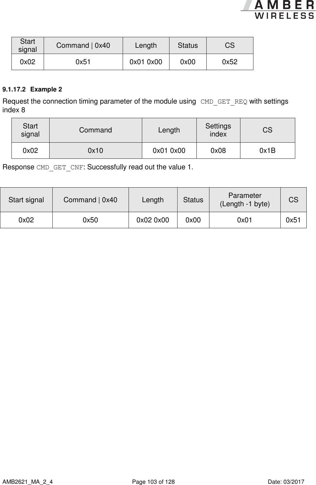
![AMB2621_MA_2_4 Page 101 of 128 Date: 03/2017 9.1.17 RF_ConnectionTiming: Modify the connection timing settings Settings index Designation Permissible values Default value Permissions Stored in Number of bytes 8 RF_ConnectionTiming 0 – 6 1 read/write Flash 1 The RF_ConnectionTiming enables the possibility to configure the timing behaviour of the module’s RF interface during an established connection. Using this parameter several predefined configurations can be chosen, which include the minimum and maximum connection interval, as well as the connection supervision timeout. The choice of the RF_ConnectionTiming primarily determines how rapidly the connection is established and data is transmitted. The lower the RF_ConnectionTiming, the more frequently the connected devices communicate with each other and thus, the more power is consumed. RF_ConnectionTiming 0 1 2 3 4 5 6 Minimum connection interval [ms] 8 20 50 200 750 2000 8 Maximum connection interval [ms] 30 75 250 1000 2250 4000 8 Connection supervision timeout [s] 4 4 4 8 15 25 4 Maximum throughput* [kB/s] Up to 3.97 Up to 1.7 Up to 0.51 - - - Up to 4.5 Current consumption *Measured with 230400 baud UART baud rate and payload size of 128Bytes between two AMB2621 modules. More information: The minimum and maximum connection interval parameters specify the borders of the connection interval as determined in the negotiation procedure between the central and the peripheral during connection setup. The connection interval defines the frequency of communication during connection setup and data transmission.](https://usermanual.wiki/AMBER-Wireless/AMB2621/User-Guide-3370134-Page-101.png)
![AMB2621_MA_2_4 Page 102 of 128 Date: 03/2017 If an AMB2621 module A (central) connects to an AMB2621 module B (peripheral), the connection interval settings of the central are used for connection setup. If both modules have different connection interval settings the peripheral requests the central to accept the peripheral’s settings after 5s. The central accepts these settings, and thus the peripheral’s connection interval is used. If now another BLE device (e.g. a smart phone) connects as central to an AMB2621 module (peripheral) and the connection interval settings do not coincide, the AMB2621 requests the smart phone to accept its settings after 5s. If the cell phone does not accept the settings, it will be requested a further 3 times with a delay of 10s. If the peripheral’s settings request have been rejected in all cases the connection will be shut down. If the smart phone itself requests to update the connection interval of the AMB2621, the module accepts the request. Reversely, if an AMB2621 (central) connects to another BLE device (peripheral) and the connection interval settings do not coincide, the AMB2621 accepts all requests of the peripheral to update the connection parameter settings. The connection supervision timeout defines the time after which an already established connection is considered as lost, when no further communication has occurred. Please ensure that all members (AMB2621s, cell phones and other BLE devices) of a network use the same connection timing parameters to avoid connection problems and changes of the connection interval during an opened connection. To connect to an Android or iOS device, please first review their supported settings [1]. The minimal value of the minimum connection interval that is supported by iOS is 30ms! 9.1.17.1 Example 1 Set the connection factor to 0x00 using CMD_SET_REQ with settings index 8. Start signal Command Length Settings index Parameter (Length -1 byte) CS 0x02 0x11 0x02 0x00 0x08 0x00 0x19 Response CMD_SET_CNF: Successfully modified the setting.](https://usermanual.wiki/AMBER-Wireless/AMB2621/User-Guide-3370134-Page-102.png)
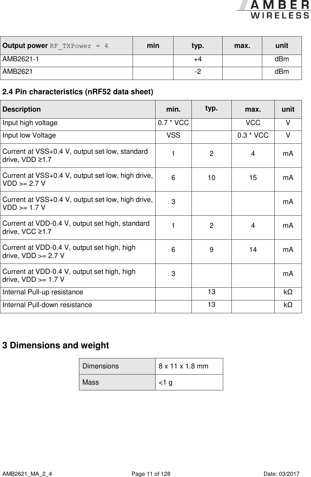
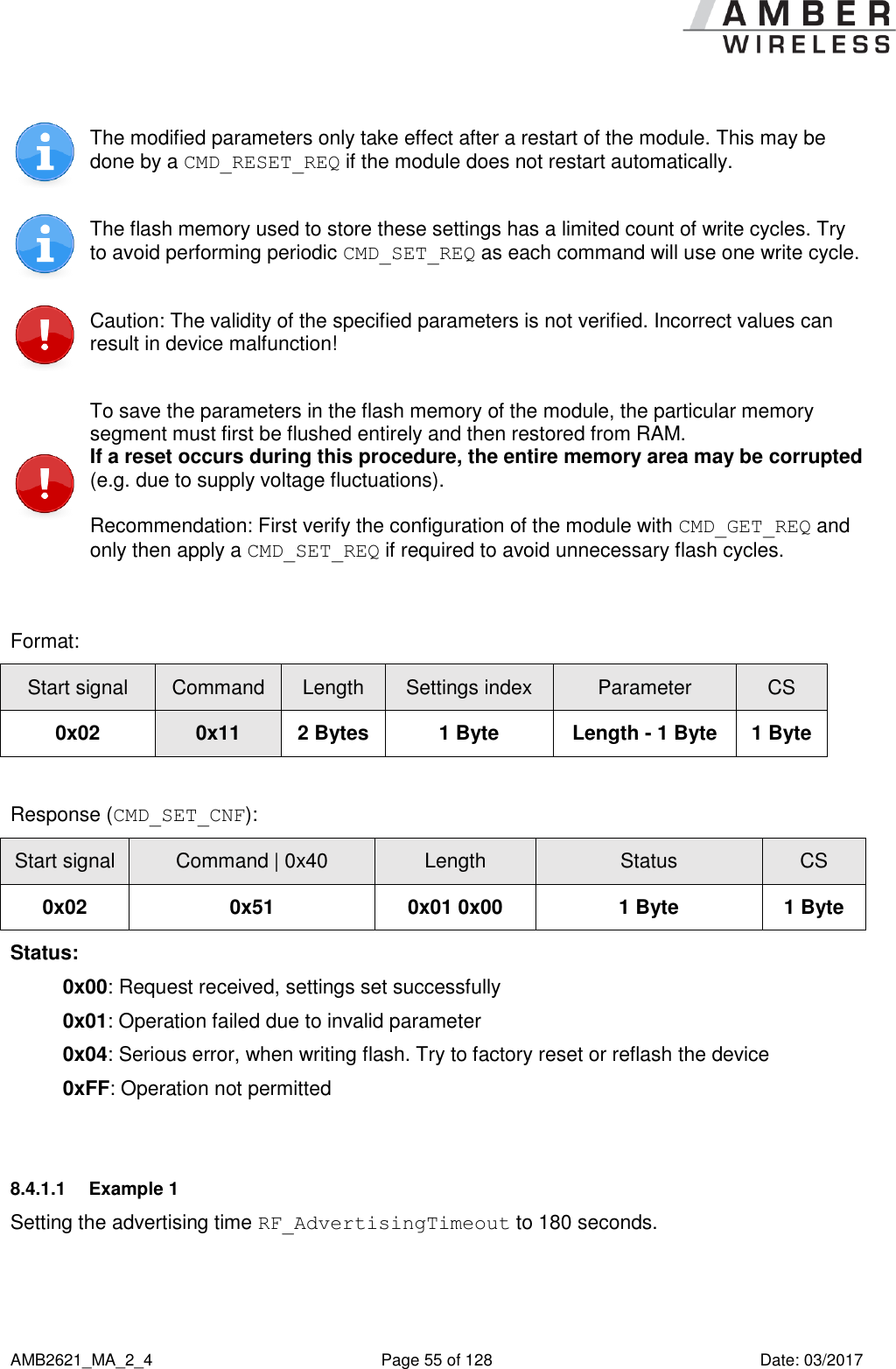
![AMB2621_MA_2_4 Page 104 of 128 Date: 03/2017 9.1.18 RF_TXPower: Modify the output power Settings index Designation Permissible values Default value Permissions Stored in Number of bytes 17 RF_TXPower See description 4 read/write Flash 1 This setting determines the output power in dBm of the module. The value has to be entered in hexadecimal and as two’s complement. The permissible values are listed in the following table. Permissible values Decimal [dBm] -40 -30 -20 -16 -12 -8 -4 0 +4 Two’s complement, hexadecimal 0xD8 0xE2 0xEC 0xF0 0xF4 0xF8 0xFC 0x00 0x04 9.1.18.1 Example 1 Set the output power of the module to -8 dBm, which is 0xF8 in two’s complement notation, using CMD_SET_REQ with settings index 17 Start signal Command Length Settings index Parameter CS 0x02 0x11 0x02 0x00 0x11 0xF8 0xF8 Response CMD_SET_CNF: Successfully modified the setting. Start signal Command | 0x40 Length Status CS 0x02 0x51 0x01 0x00 0x00 0x52 9.1.18.2 Example 2 Request the output power of the module using CMD_GET_REQ with settings index 17 Start signal Command Length Settings index CS 0x02 0x10 0x01 0x00 0x11 0x02 Response CMD_GET_CNF: Successfully read out the value 0x04 = 4dBm](https://usermanual.wiki/AMBER-Wireless/AMB2621/User-Guide-3370134-Page-104.png)

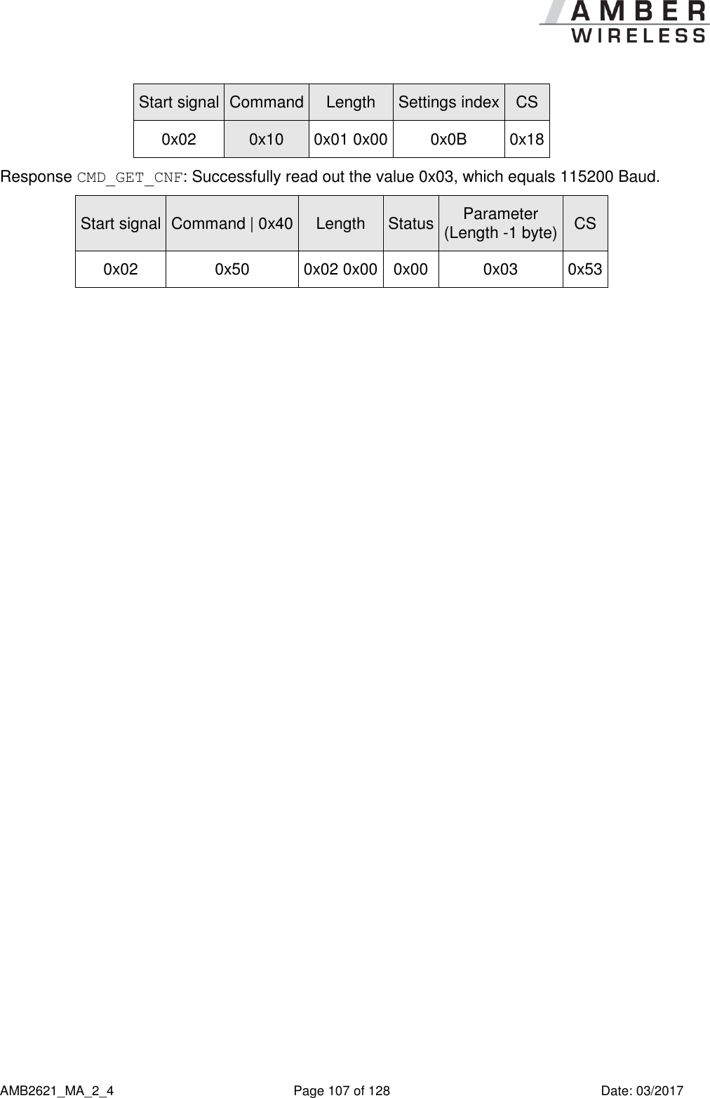
![AMB2621_MA_2_4 Page 106 of 128 Date: 03/2017 9.1.19 UART_BaudrateIndex: Configure the UART speed Settings index Designation Permissible values Default value Permissions Stored in Number of bytes 11 UART_BaudrateIndex See description 3 read/write Flash 1 This parameter defines the baud rate used by the module’s UART. Possible values are: UART_BaudrateIndex 0 1 2 3 4 Rate [Baud] 9600 19200 38400 115200 230400 After changing the baud rate using the CMD_SET_REQ the module restarts using the new baud rate. Therefore don’t forget to update the baud rate of the connected host to be able to further use the module’s UART. Please note that due to the HF-activity of the chip, single bytes on the UART can get lost, when using a very fast UART data rate. In case of corrupted UART communication the module cannot interpret the sent request and thus does not return a confirmation. 9.1.19.1 Example 1 Set the baud rate index to 0x04 (230400 Baud) using CMD_SET_REQ with settings index 11. Start signal Command Length Settings index Parameter (Length -1 byte) CS 0x02 0x11 0x02 0x00 0x0B 0x04 0x1E Response CMD_SET_CNF: Successfully modified the setting. Start signal Command | 0x40 Length Status CS 0x02 0x51 0x01 0x00 0x00 0x52 9.1.19.2 Example 2 Request the baud rate index of the module using CMD_GET_REQ with settings index 11](https://usermanual.wiki/AMBER-Wireless/AMB2621/User-Guide-3370134-Page-106.png)
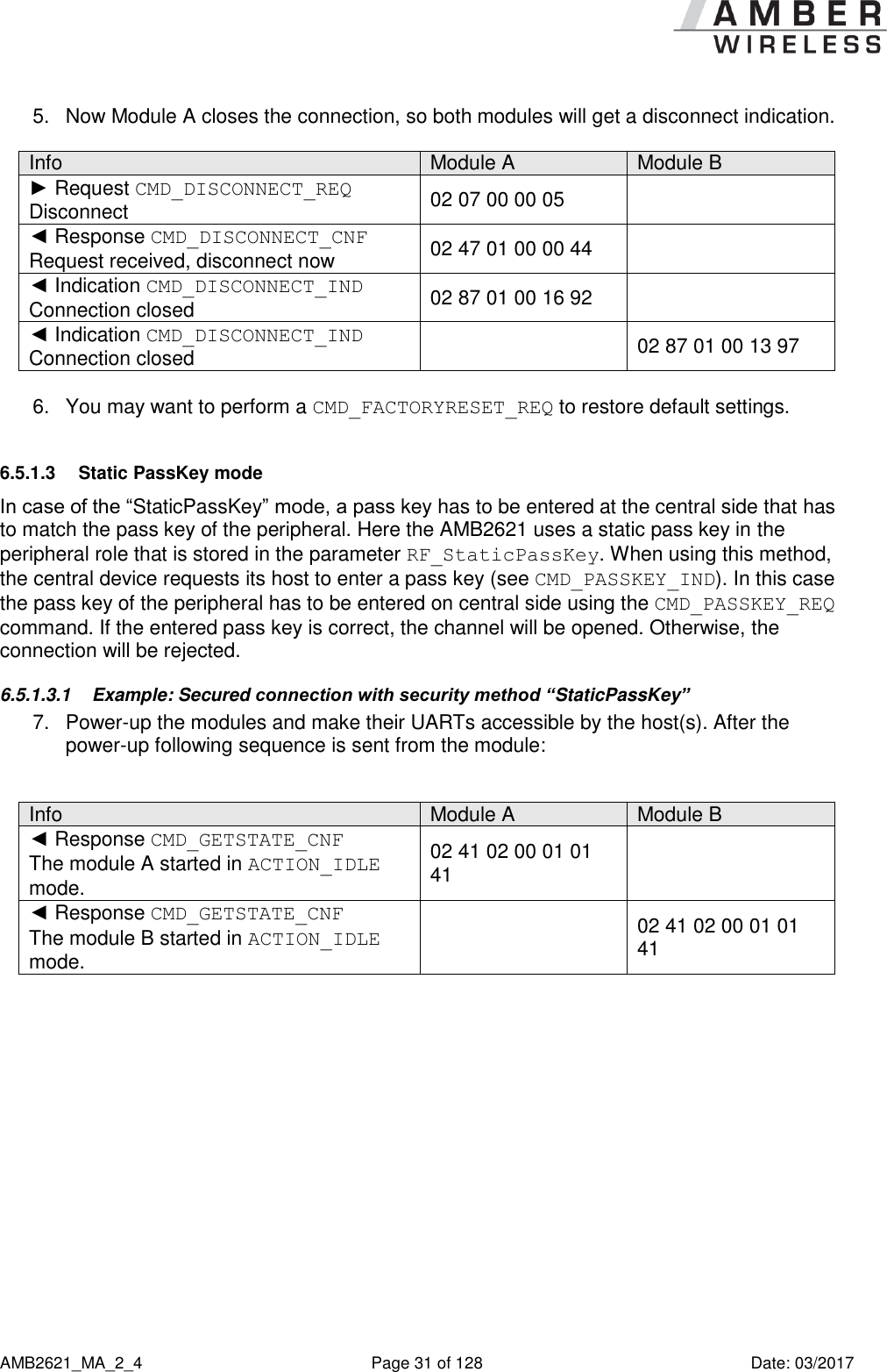
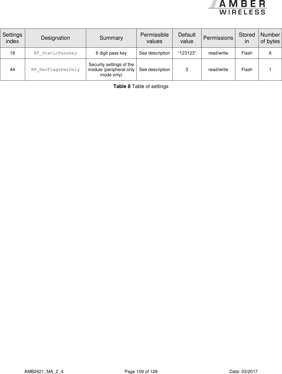
![AMB2621_MA_2_4 Page 108 of 128 Date: 03/2017 9.2 List of user settings Settings index Designation Summary Permissible values Default value Permissions Stored in Number of bytes 1 FS_FWVersion Version of the firmware - - read Flash 3 2 RF_DeviceName Name of the module See description “A2621” read/write Flash 1-5 3 FS_MAC MAC address of the module - - read Flash 6 4 FS_BTMAC BLE conform MAC address of the module - - read Flash 6 5 RF_OwnLTK Long term key used when it is connected by another device See description “AMB_DEFAULT_KEY” read/write Flash 7-16 6 RF_PeerLTK Long term key used to connect to another device See description “AMB_DEFAULT_KEY” read/write Flash / RAM 7-16 7 RF_AdvertisingTimeout Time [s] after advertising stops. LSB first 0 (infinite) 1 – 65535 0 read/write Flash 2 8 RF_ConnectionTiming Module connection timing configuration 0 – 6 1 read/write Flash 1 9 RF_ScanTiming Module advertising and scanning timing configuration 0 – 5 1 read/write Flash 1 10 RF_ScanFactor Factor between scan interval and scan window 1 – 10 2 read/write Flash 1 11 UART_BaudrateIndex Baud rate of the UART See description 3 read/write Flash 1 12 RF_SecFlags Security settings of the module See description 0 read/write Flash 1 13 RF_ScanFlags Scan settings of the module See description 0 read/write Flash 1 14 RF_BeaconFlags Beacon settings of the module See description 0 read/write Flash 1 15 FS_DeviceInfo Information about the chip - - read Flash 12 16 FS_SerialNumber Serial number of the module - - read Flash 3 17 RF_TXPower Output power [dBm] Two’s complement See description 4 read/write Flash 1](https://usermanual.wiki/AMBER-Wireless/AMB2621/User-Guide-3370134-Page-108.png)

![AMB2621_MA_2_4 Page 121 of 128 Date: 03/2017 14 References [1] Bluetooth Core Specifications 4.0 and 4.2 Source: https://www.bluetooth.com/specifications/adopted-specifications [2] Nordic Semiconductor Infocenter Source: http://infocenter.nordicsemi.com](https://usermanual.wiki/AMBER-Wireless/AMB2621/User-Guide-3370134-Page-121.png)