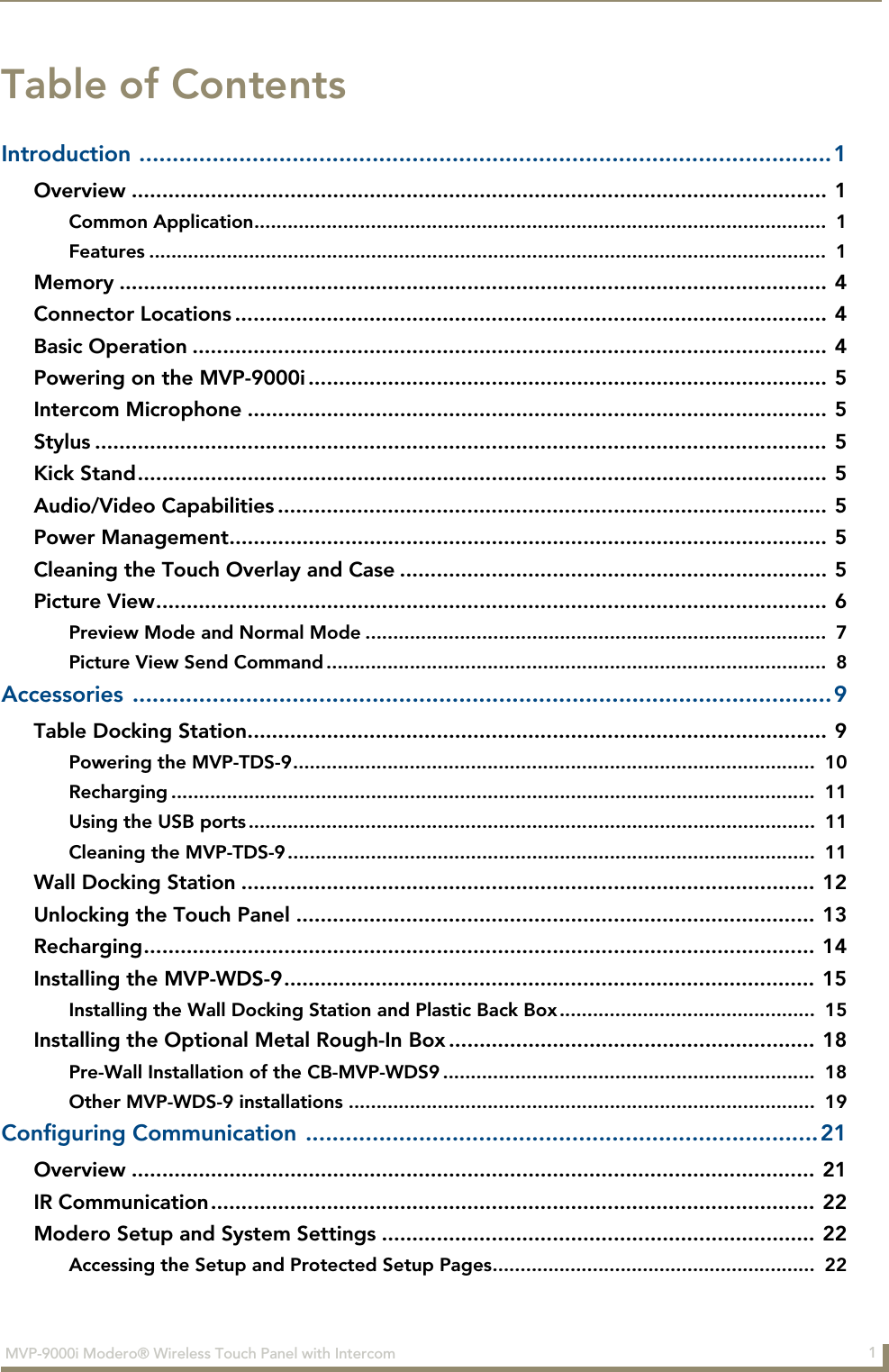
AMX MVP9 WiFi Touch Panel User Manual MVP 9000i OperationReferenceGuide
AMX LLC WiFi Touch Panel MVP 9000i OperationReferenceGuide
UserManual.wiki
>
AMX
>
MVP9 User Manual
>
Final User's Manual
Contents
1.
Install Guide
2.
Final User's Manual
Final User's Manual
Navigation menu
Upload a User Manual
Namespaces
Wiki Guide
HTML
PDF
Info
Views
User Manual
Discussion / Help
Navigation
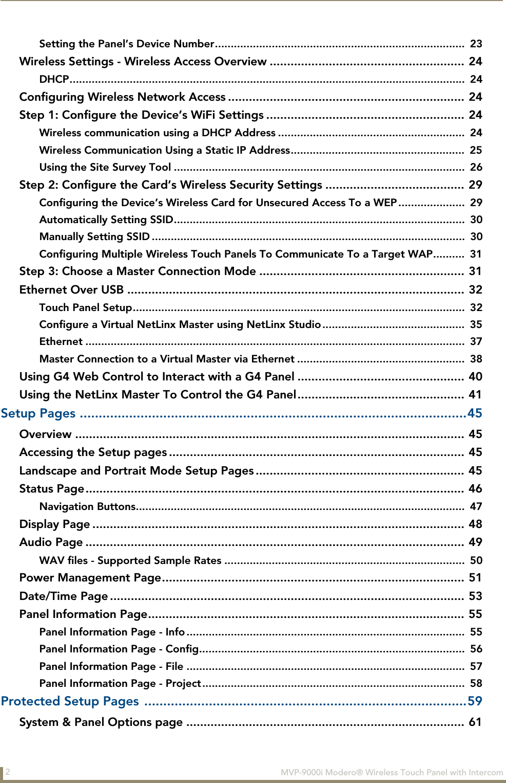

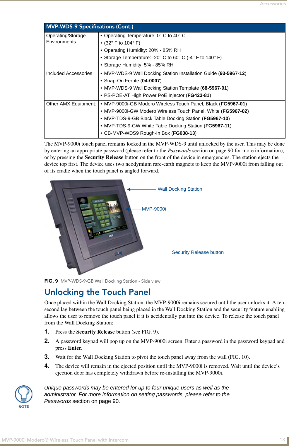
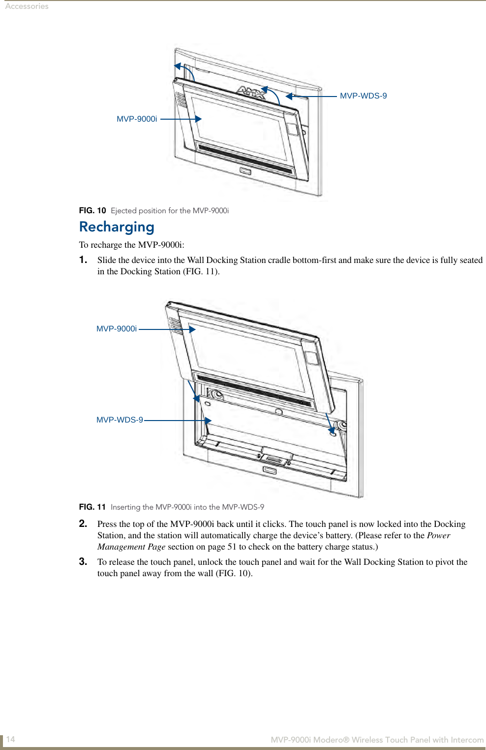
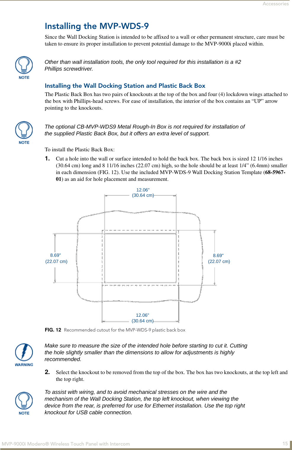
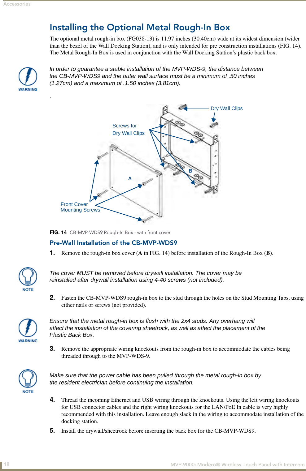
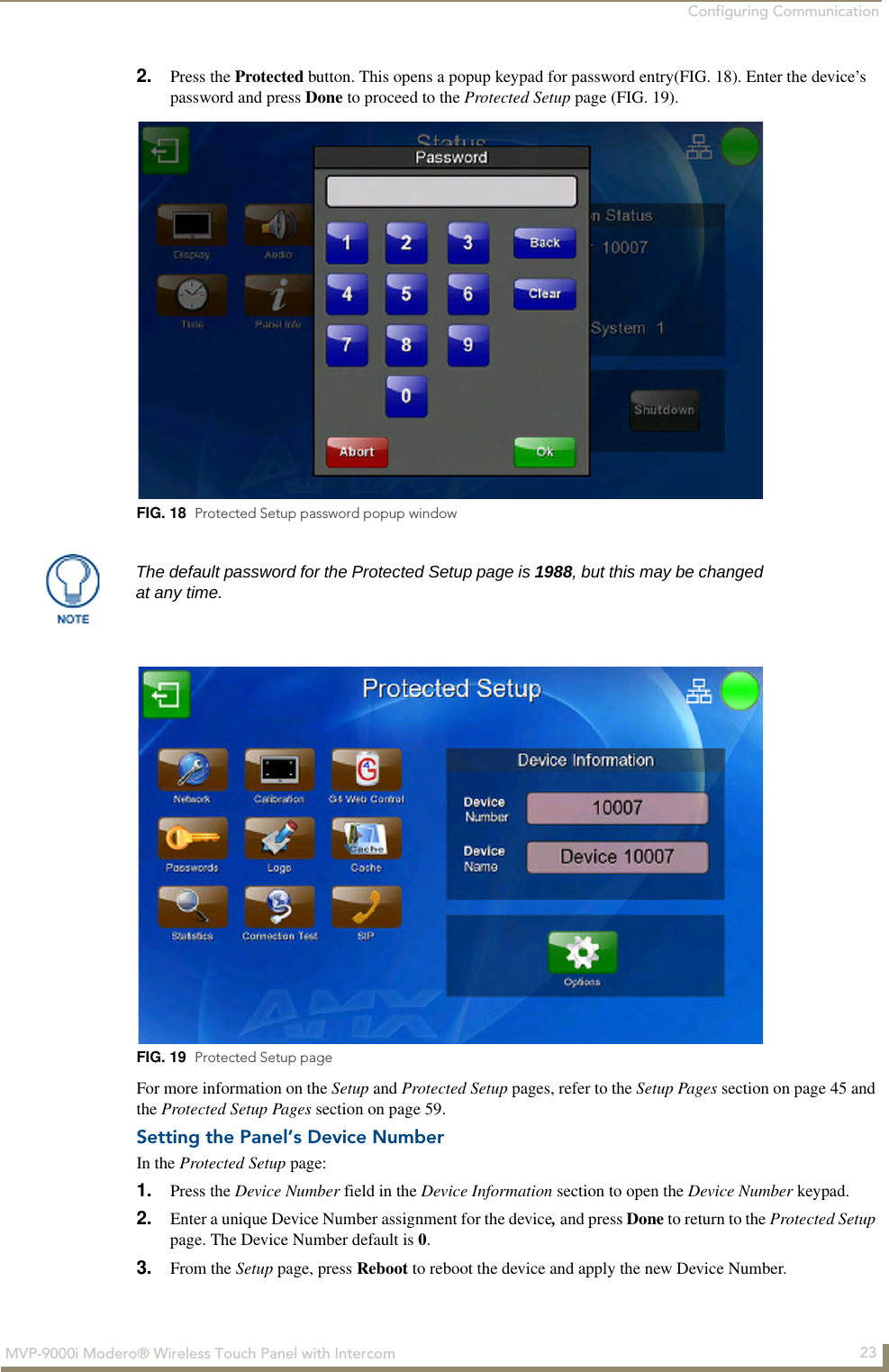
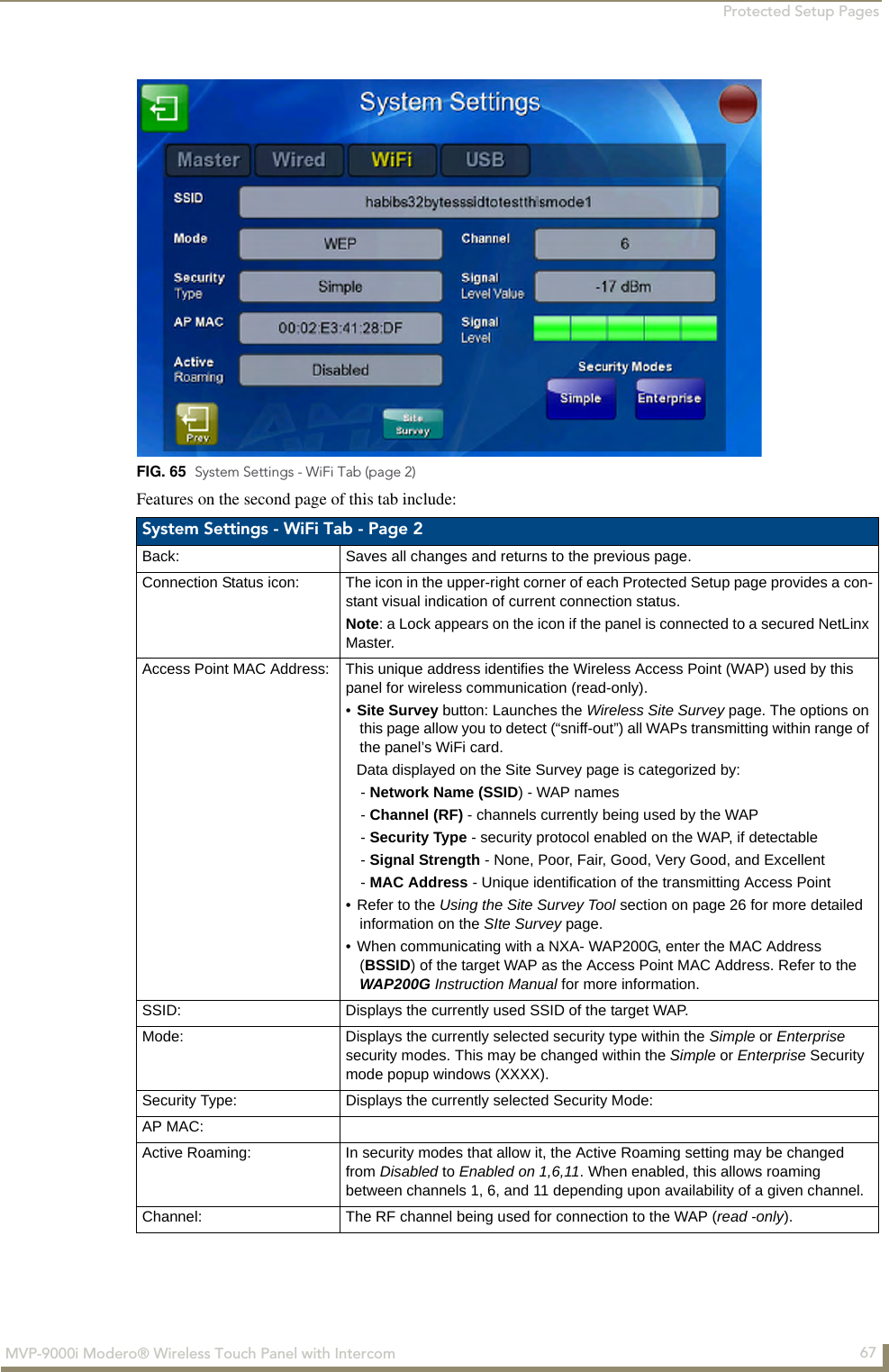
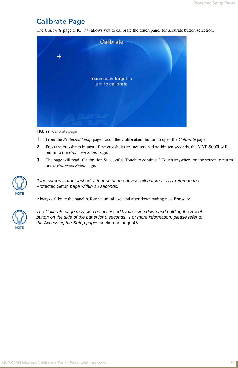
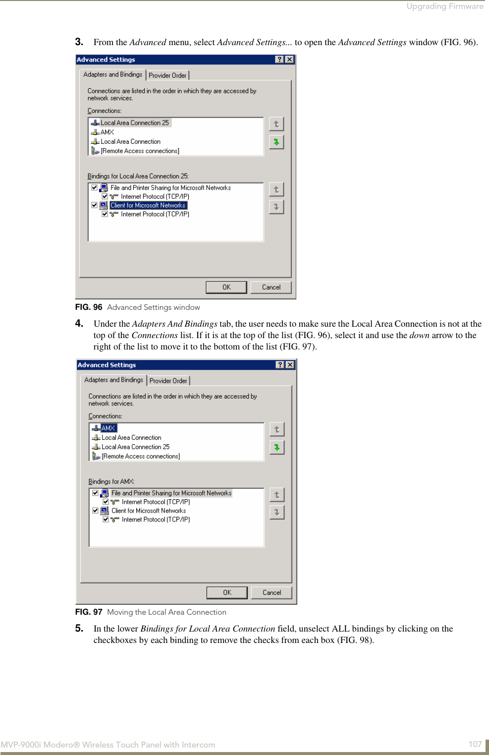
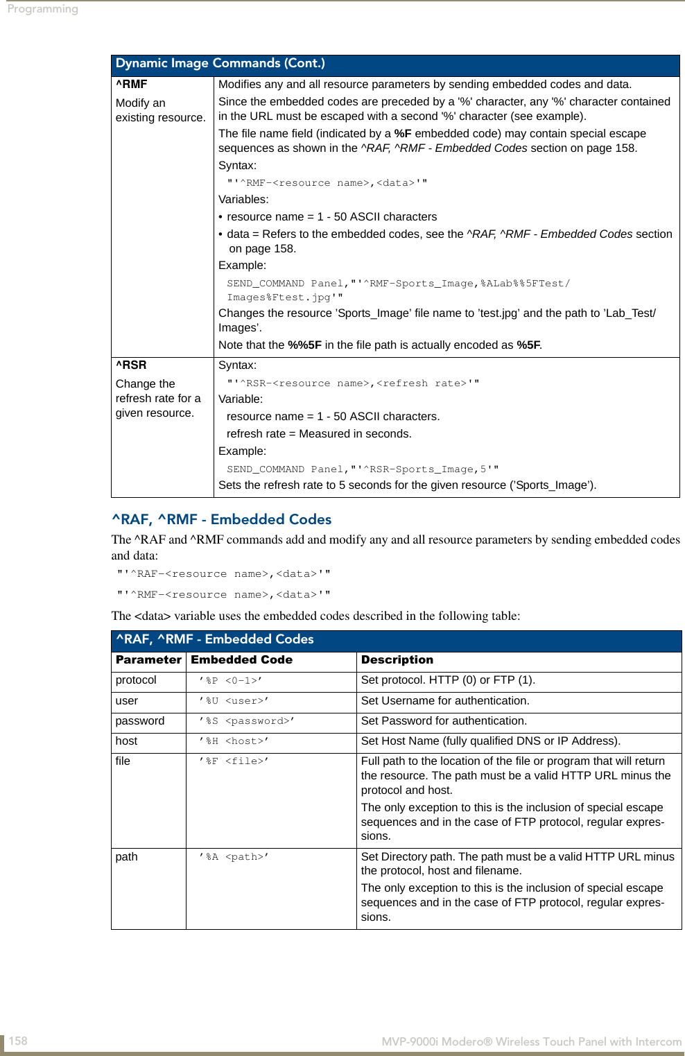
![Accessories16 MVP-9000i Modero® Wireless Touch Panel with Intercom3. Connect the PS-POE-AT High-Power PoE Injector to a power source. Connect the PS-POE-AT to an Ethernet switch on the network via one length of Ethernet cable and insert one length of Ethernet cable for connection to the Wall Docking Station.4. Run the Ethernet cable through the knockout into the back box. Pull out about six inches (15.25cm) of cable into the back box to facilitate installation of the MVP-WDS-9.5. Slide the plastic back box into the hole, being careful not to twist or pinch the cable, and set it flush with the wall. Make sure that all of the lockdown wings are folded into their slots before attempting to insert the box. For ease of installation, the inside of the box has the direction “UP” labeled for reference.6. Extend the wings on the sides of the box by tightening the screws inside the box. Not all of the wings must be extended to lock the box in place, but extending a minimum of the top and bottom wings is highly recommended. Apply enough pressure to the screw head to keep the box flush with the wall: this ensures that the wing will tighten up against the inside of the wall.7. Attach the included snap-on ferrite to the Ethernet cable, as close to the RJ-45 connector as possible. Attach the cable to the Ethernet Port (FIG. 13).8. Firmly seat the device against the back box. Make sure that the tab connector at the bottom of the device is locked into the back box.9. Insert the two installation screws from the MVP-WDS-9 Installation Kit into the screw holes in the interior compartment of the device and tighten them to anchor the device to the back box.Make absolutely certain that the box is in its intended position. Once the box lockdown wings are extended within the box’s hole within the wall, removing the box will be extremely difficult without damaging the wall in the process.The maximum recommended torque to screw in the wings on the plastic back box is 5 IN-IBS [5(NI-CM)]. Applying excessive torque while tightening the wing screws, such as with powered screwdrivers, can strip out the wings or damage the plastic back box.FIG. 13 MVP-WDS-9 - Ethernet cable pathKnockout placementin back boxRecommended Ethernet installation Recommended USB installationEthernet portFerrite installationpositionRecommendedEthernet cablepathFor ease of installation, put each screw on a neodymium magnet in the device’s interior compartment to keep them on hand until they are needed.](https://usermanual.wiki/AMX/MVP9.Final-User-s-Manual/User-Guide-1376986-Page-31.png)
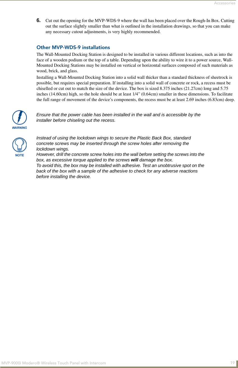

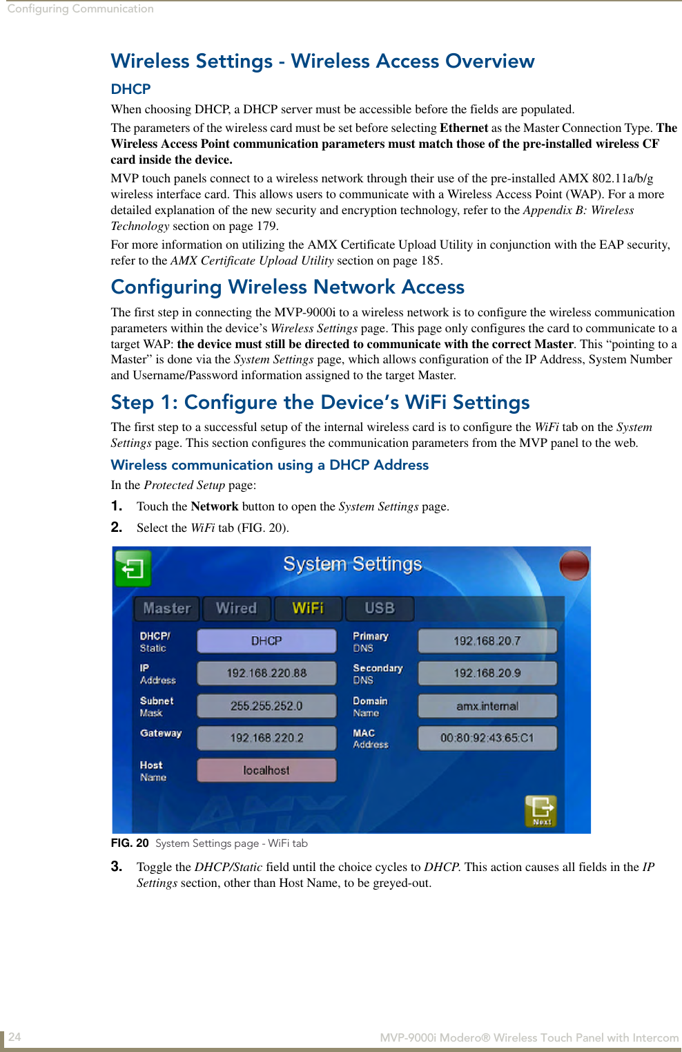
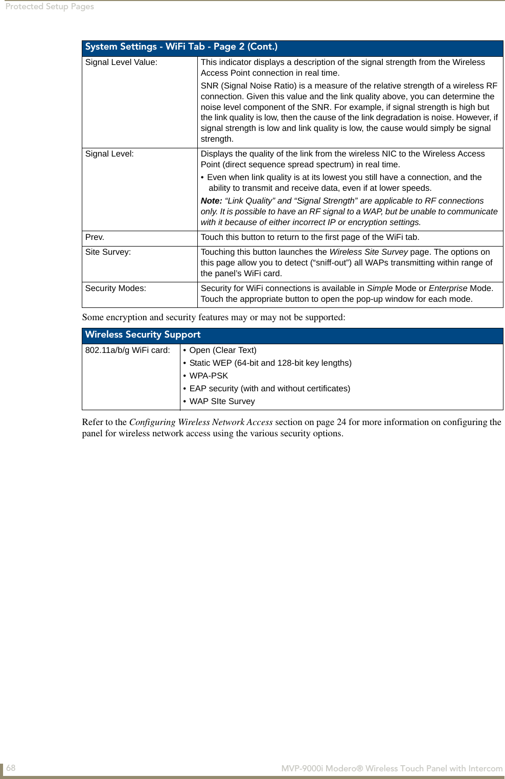
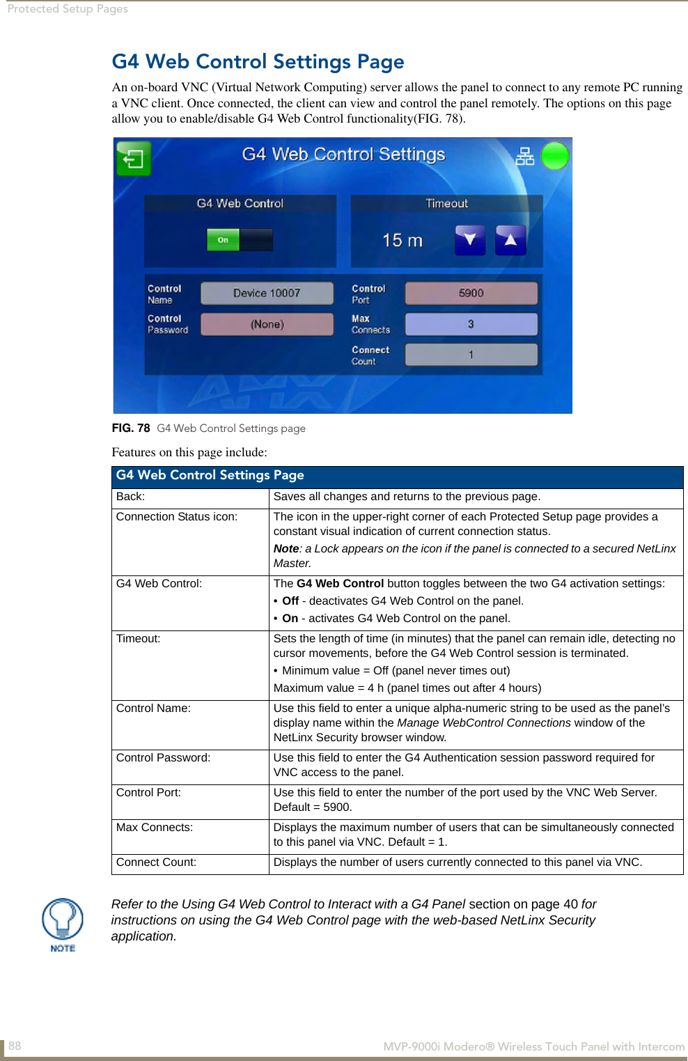
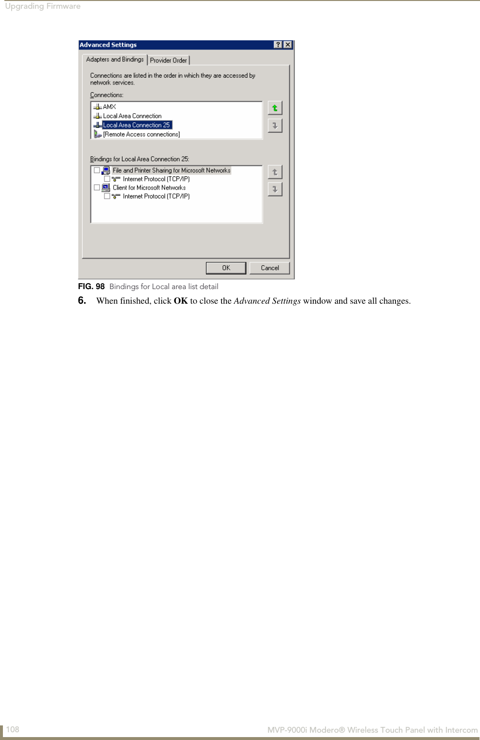
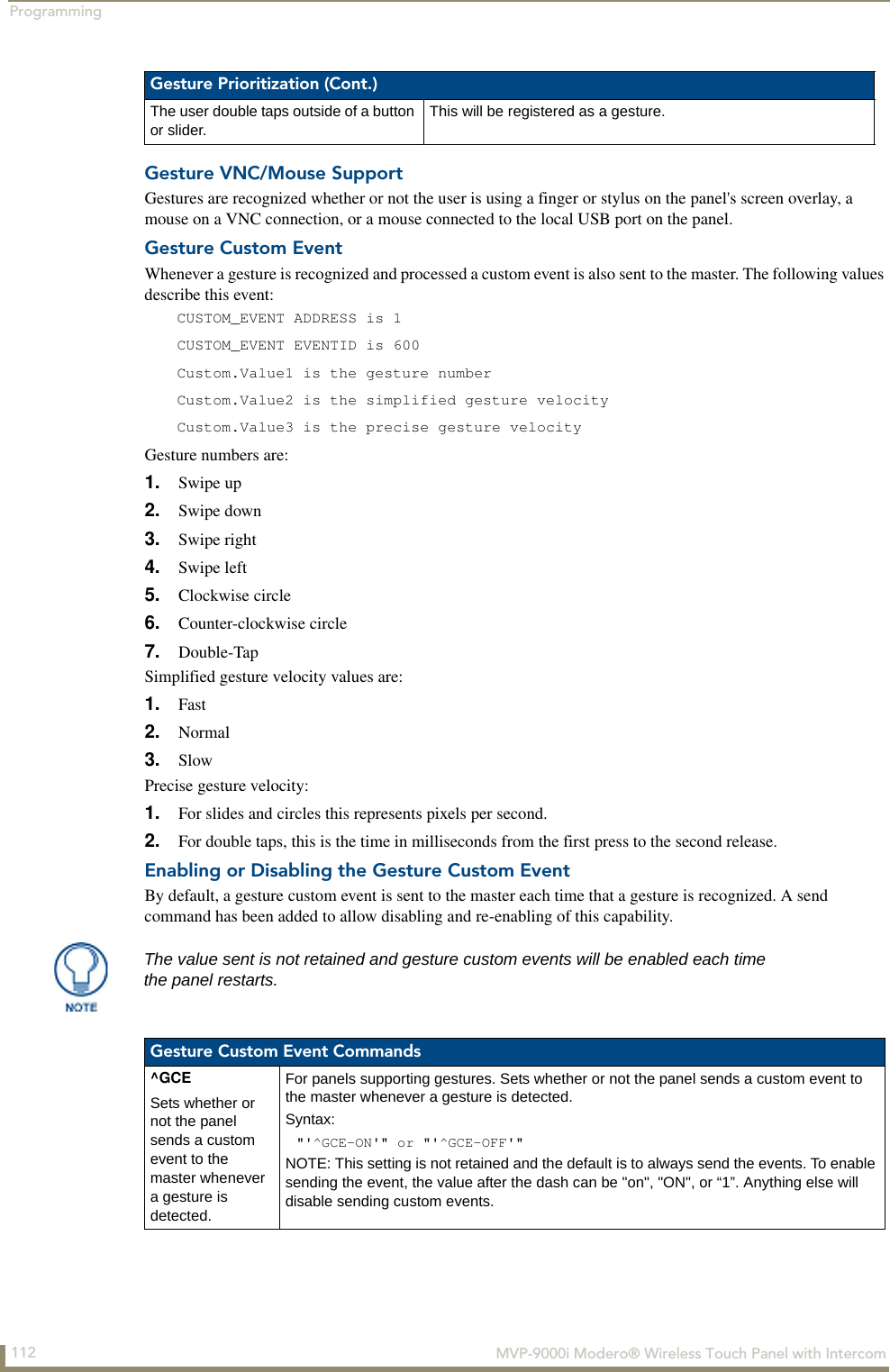
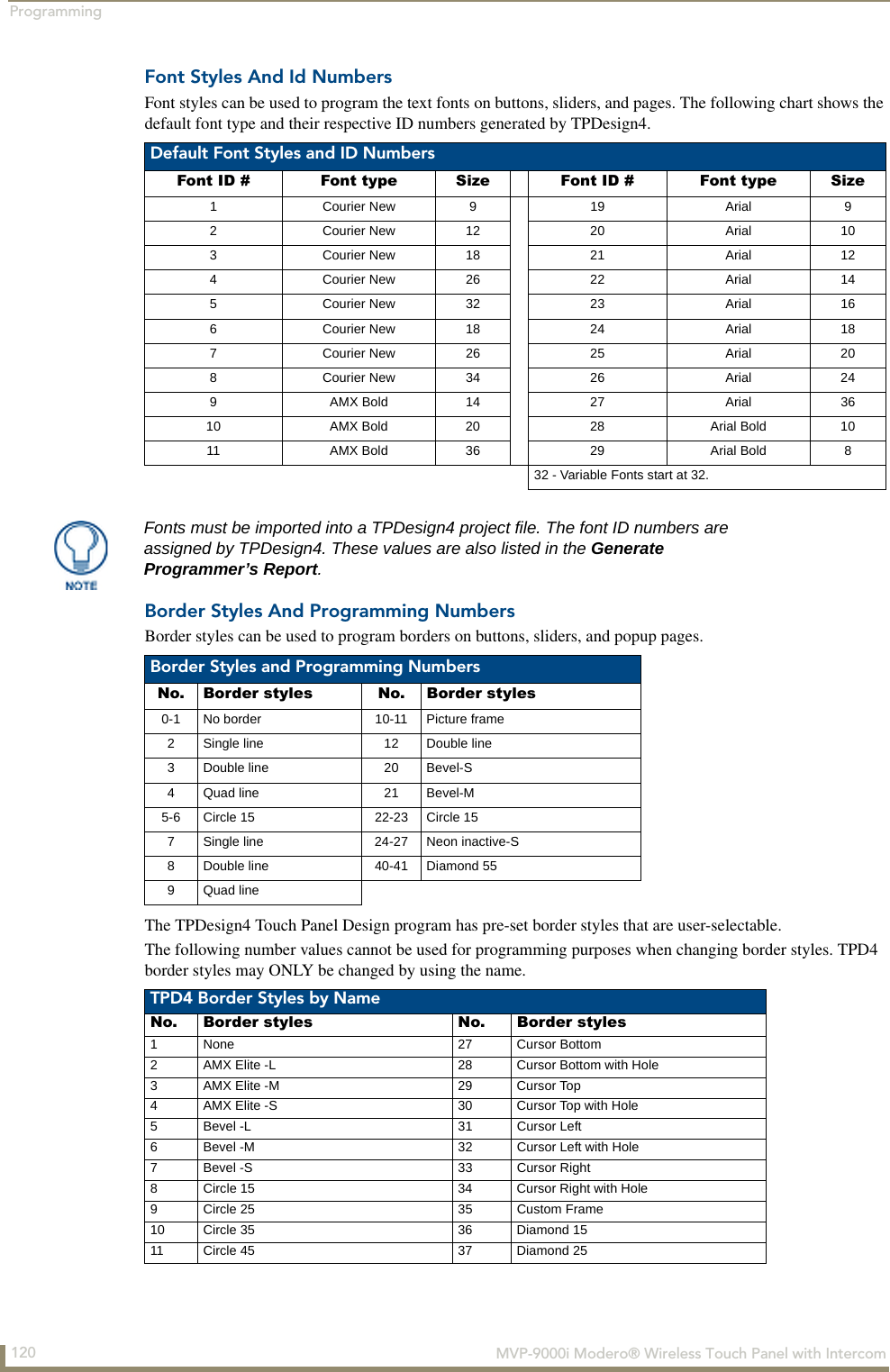
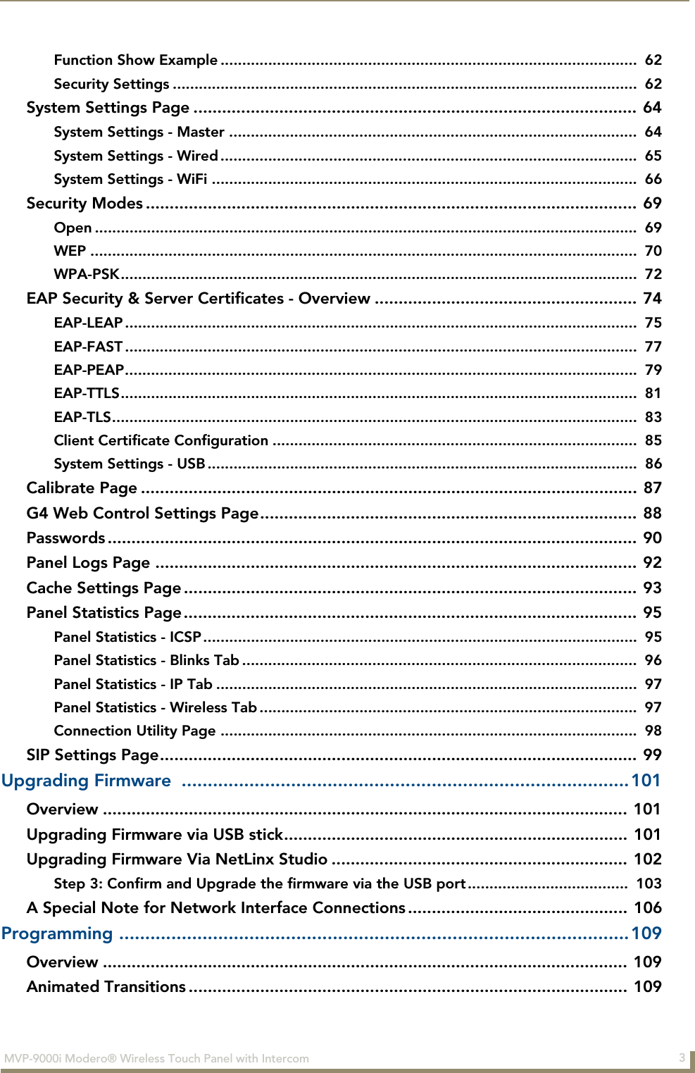
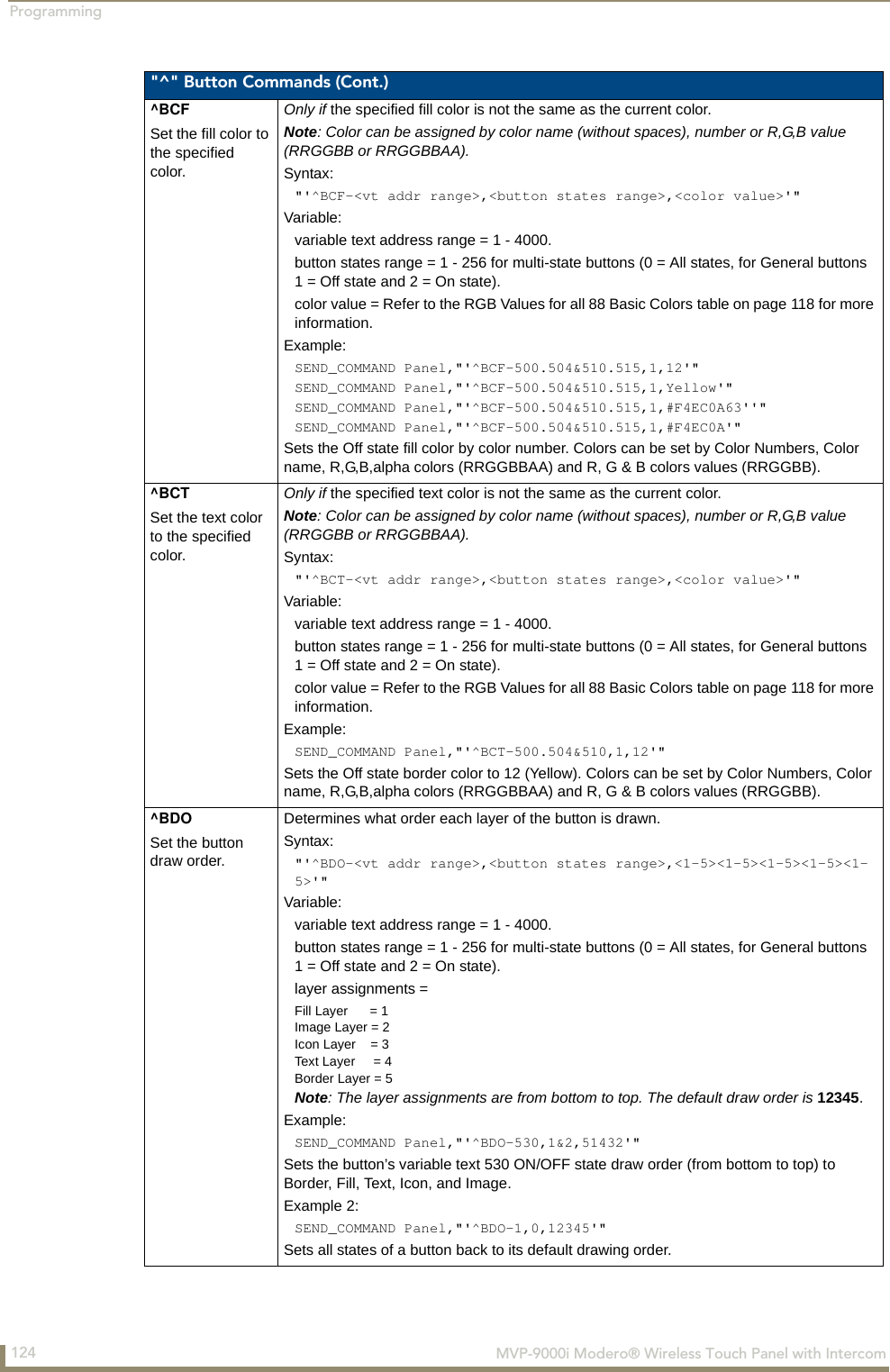
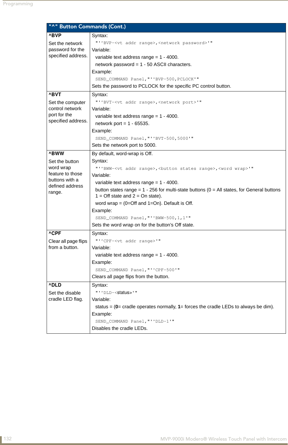
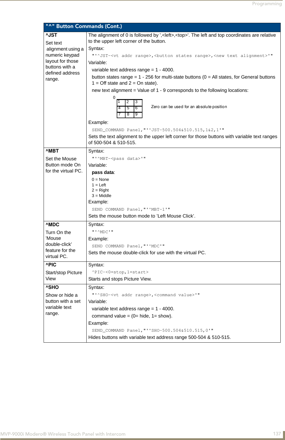
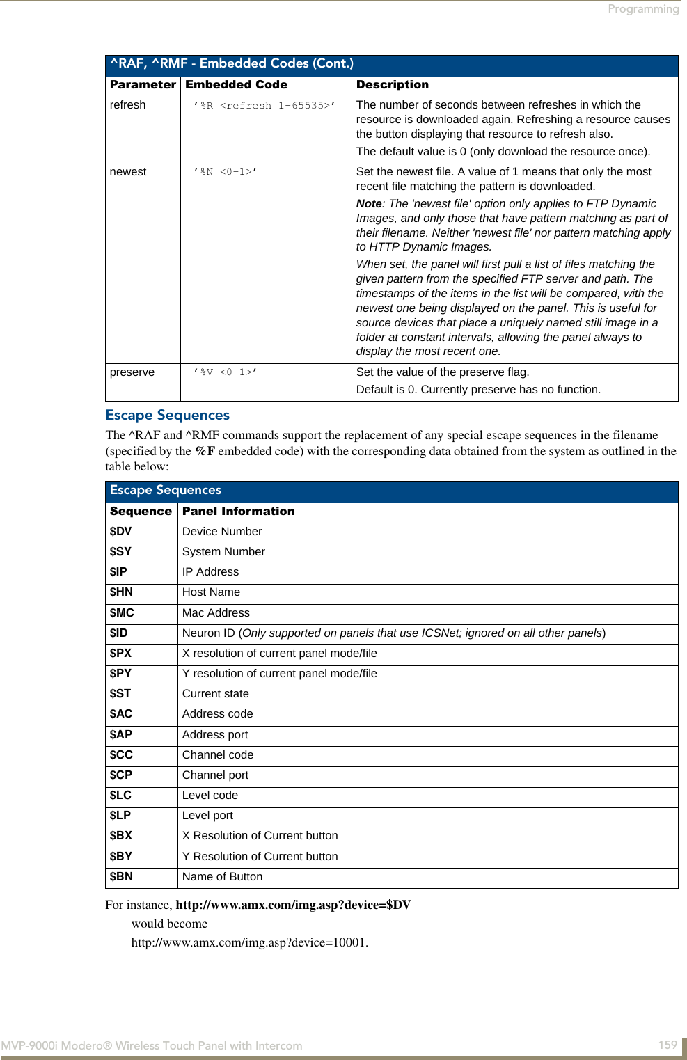
![Programming122 MVP-9000i Modero® Wireless Touch Panel with Intercom"^" Button CommandsThese Button Commands are used in NetLinx Studio and are case insensitive.All commands that begin with "^" have the capability of assigning a variable text address range and button state range. A device must first be defined in the NetLinx programming language with values for the Device: Port: System (in all programming examples - Panel is used in place of these values).Variable text ranges allow you to target 1 or more variable text channels in a single command.Button State ranges allow you to target 1 or more states of a variable text button with a single command. "." Character is used for the 'through' notation, also the “&” character is used for the 'And' notation. TPD4 Border Styles by Name (Cont.)No. Border styles No. Border styles93 Menu Bottom Rounded 145 137 Menu Left Rounded 1594 Menu Bottom Rounded 155 138 Menu Left Rounded 2595 Menu Bottom Rounded 165 139 Menu Left Rounded 3596 Menu Bottom Rounded 175 140 Menu Left Rounded 45141 Menu Left Rounded 55 149 Menu Left Rounded 135142 Menu Left Rounded 65 150 Menu Left Rounded 145143 Menu Left Rounded 75 151 Menu Left Rounded 155144 Menu Left Rounded 85 152 Menu Left Rounded 165145 Menu Left Rounded 95 153 Menu Left Rounded 175146 Menu Left Rounded 105 154 Menu Left Rounded 185147 Menu Left Rounded 115 155 Menu Left Rounded 195148 Menu Left Rounded 125"^" Button Commands^ANIRun a button animation (in 1/10 second).Syntax: "'^ANI-<vt addr range>,<start state>,<end state>,<time>'"Variable: variable text address range = 1 - 4000.start state = Beginning of button state (0= current state).end state = End of button state.time = In 1/10 second intervals.Example:SEND_COMMAND Panel,"'^ANI-500,1,25,100'"Runs a button animation at text range 500 from state 1 to state 25 for 10 second.^APFAdd page flip action to a button if it does not already exist.Syntax:"'^APF-<vt addr range>,<page flip action>,<page name>'"Variable: variable text address range = 1 - 4000.page flip action =Stan[dardPage] - Flip to standard pagePrev[iousPage] - Flip to previous pageShow[Popup] - Show Popup pageHide[Popup] - Hide Popup pageTogg[lePopup] - Toggle popup stateClearG[roup] - Clear popup page group from all pagesClearP[age] - Clear all popup pages from a page with the specified page nameClearA[ll] - Clear all popup pages from all pagespage name = 1 - 50 ASCII characters.Example:SEND COMMAND Panel,"'^APF-400,Stan,Main Page'"Assigns a button to a standard page flip with page name 'Main Page'.](https://usermanual.wiki/AMX/MVP9.Final-User-s-Manual/User-Guide-1376986-Page-137.png)
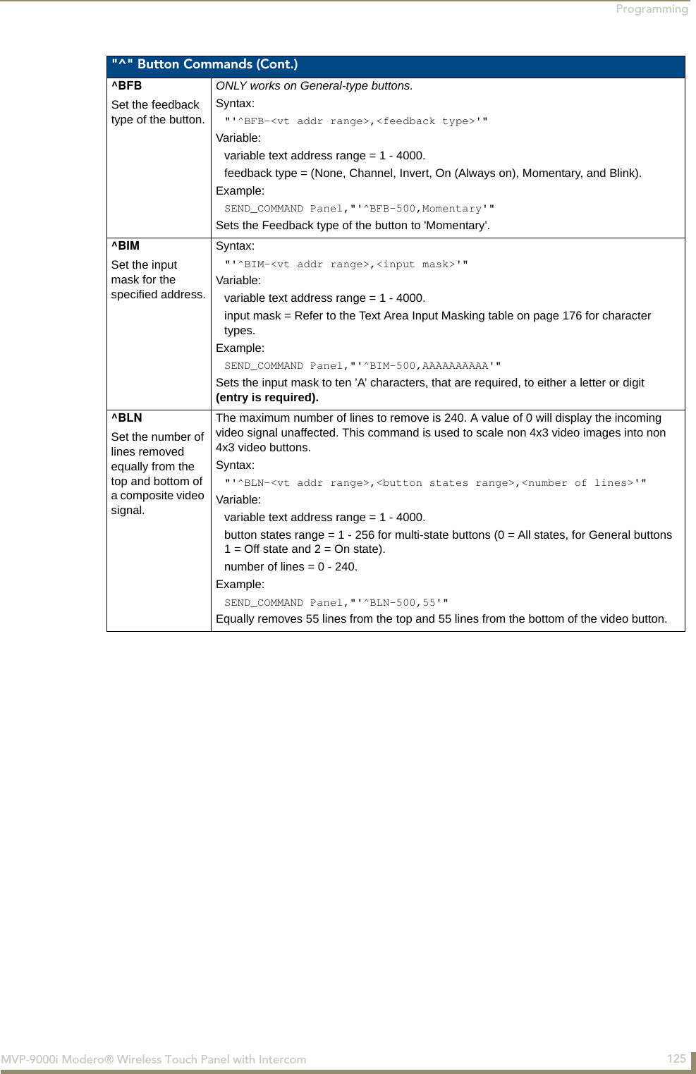
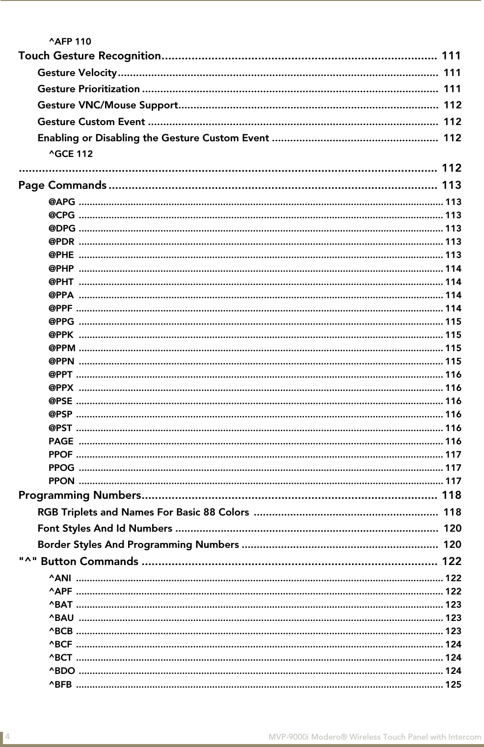
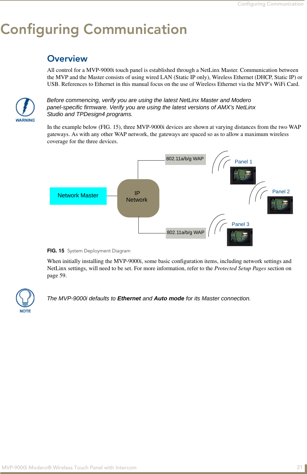
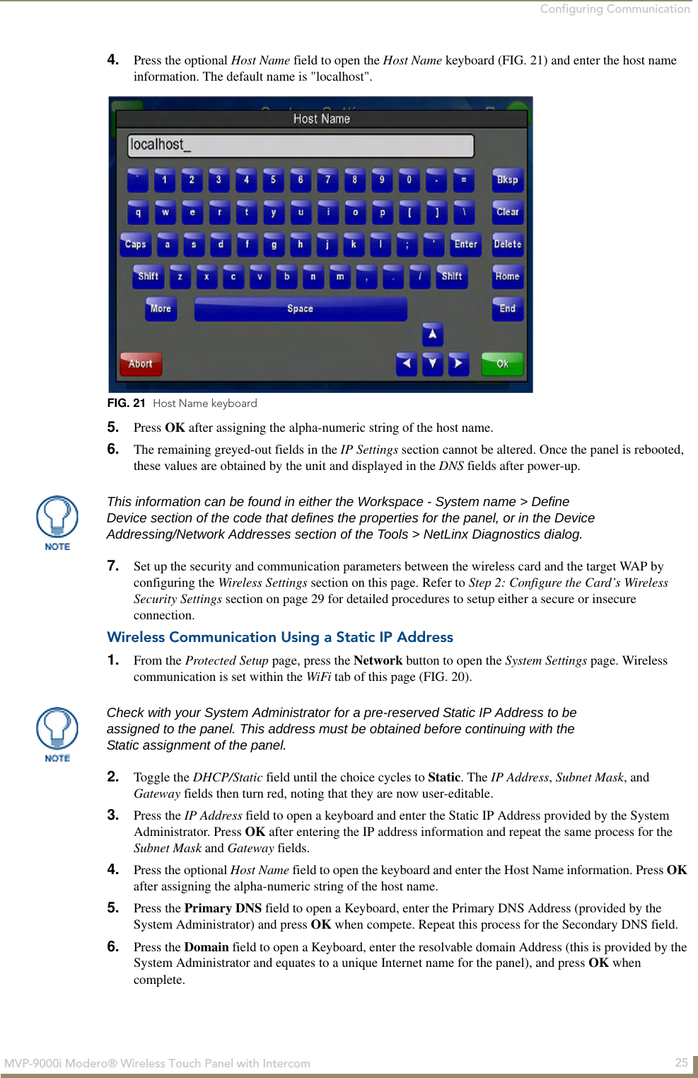
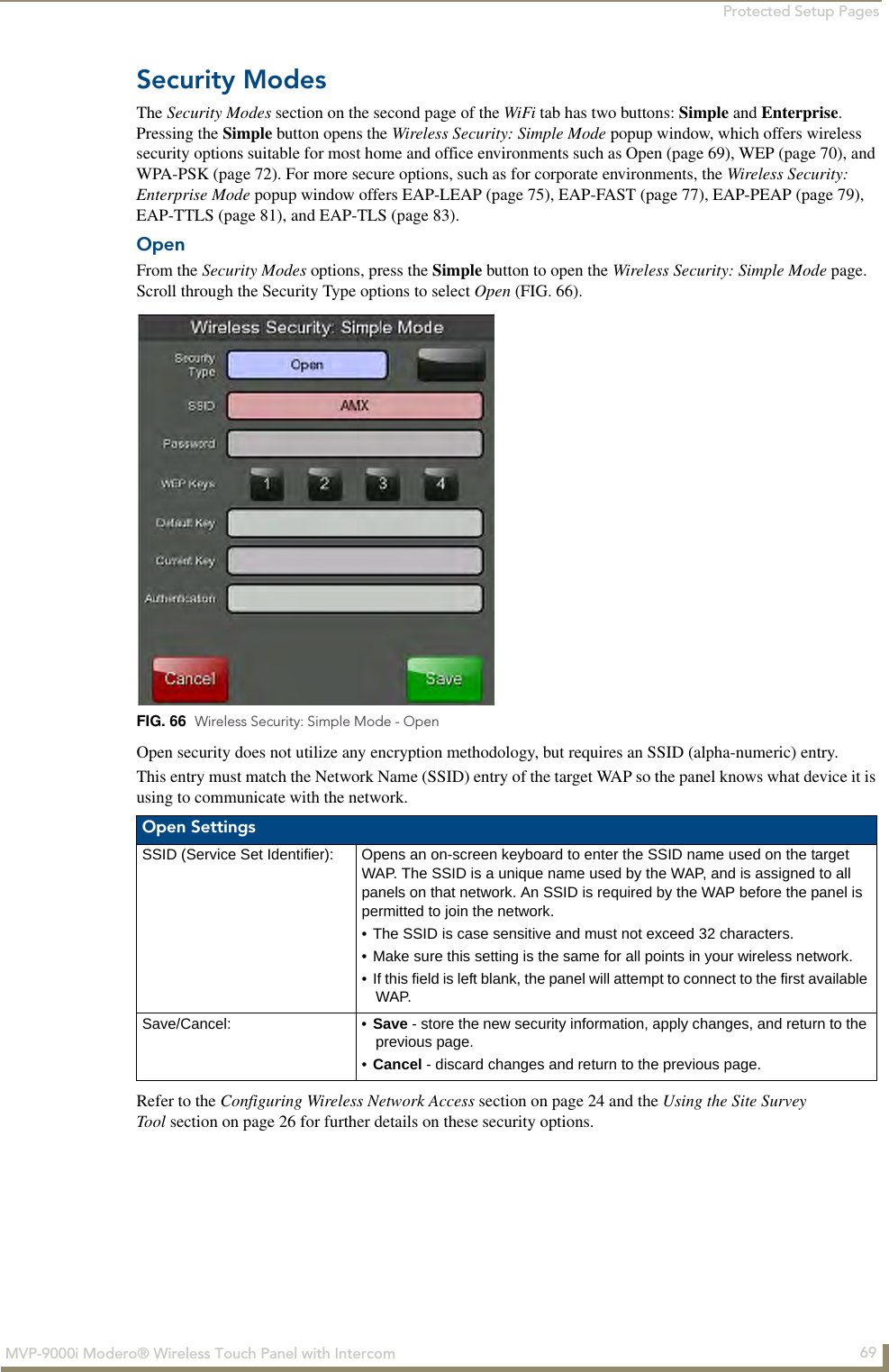
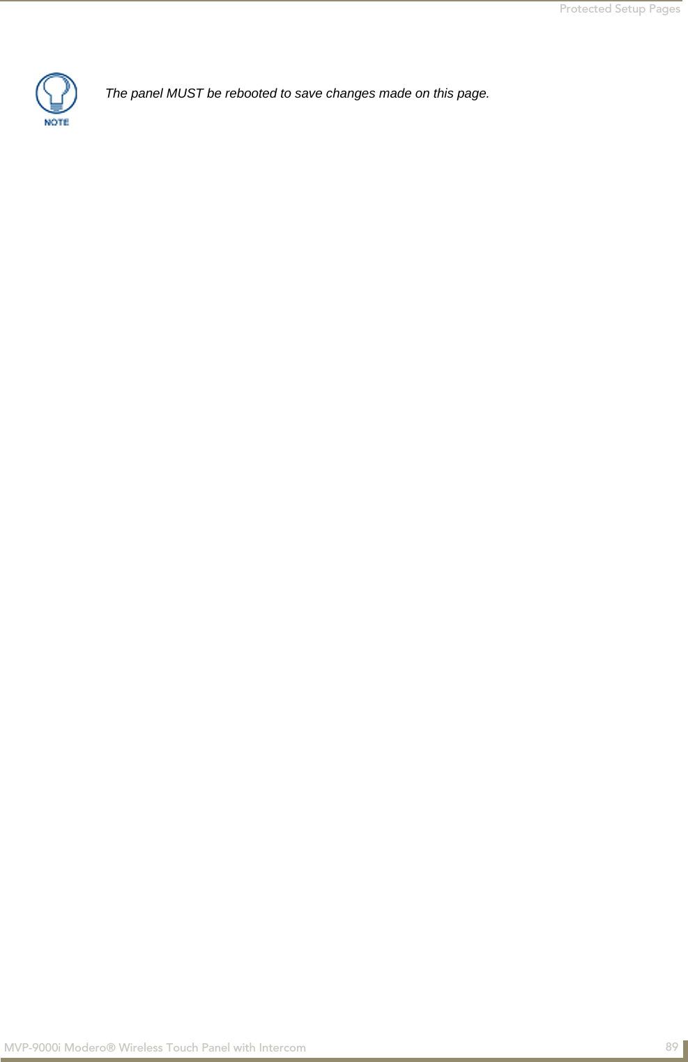
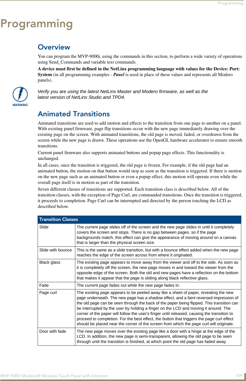
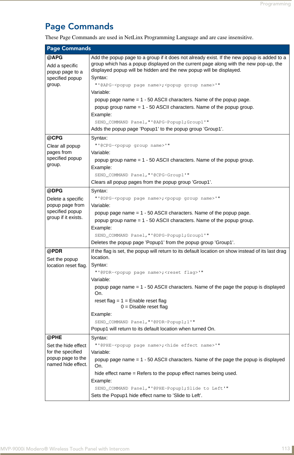
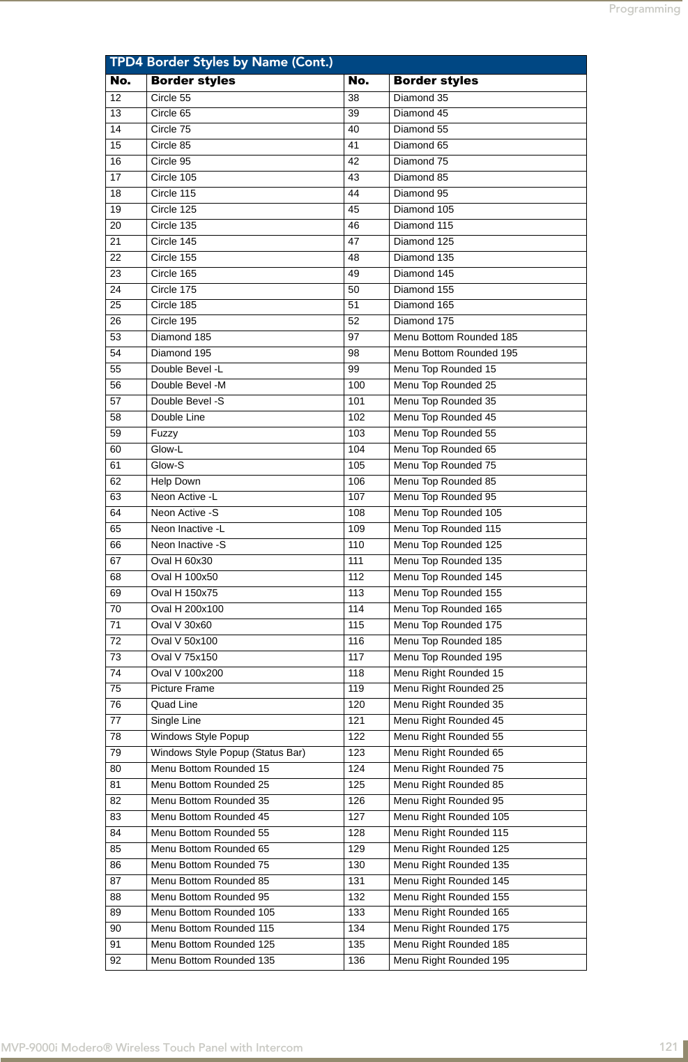
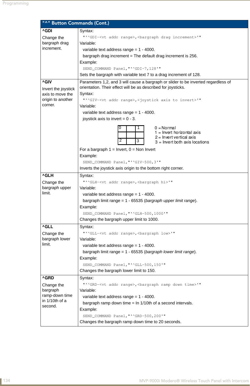
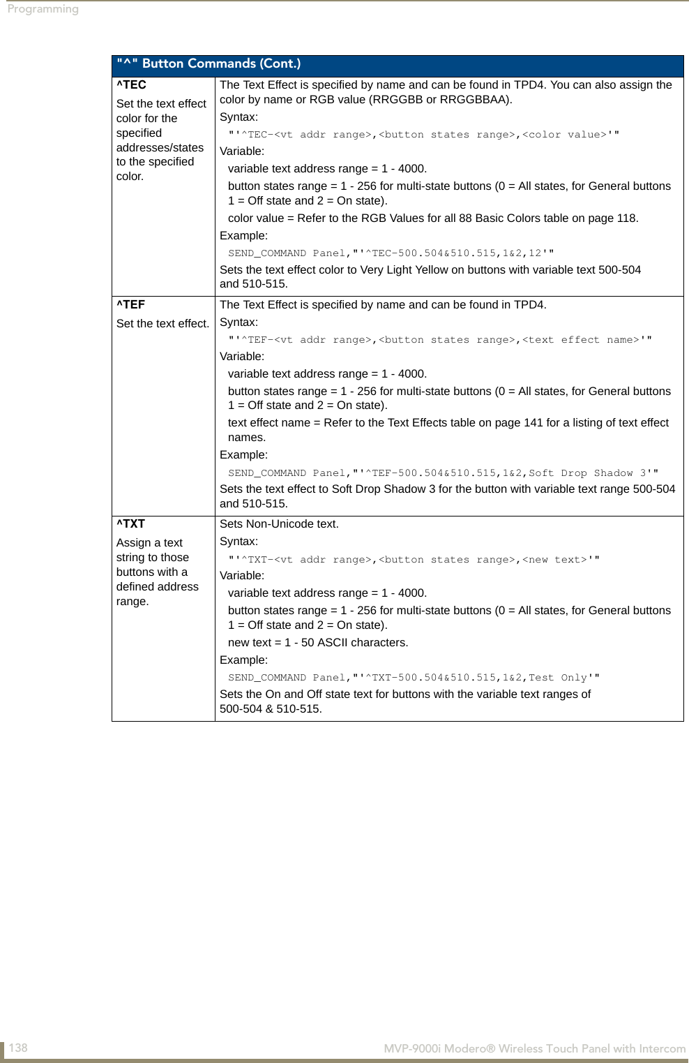
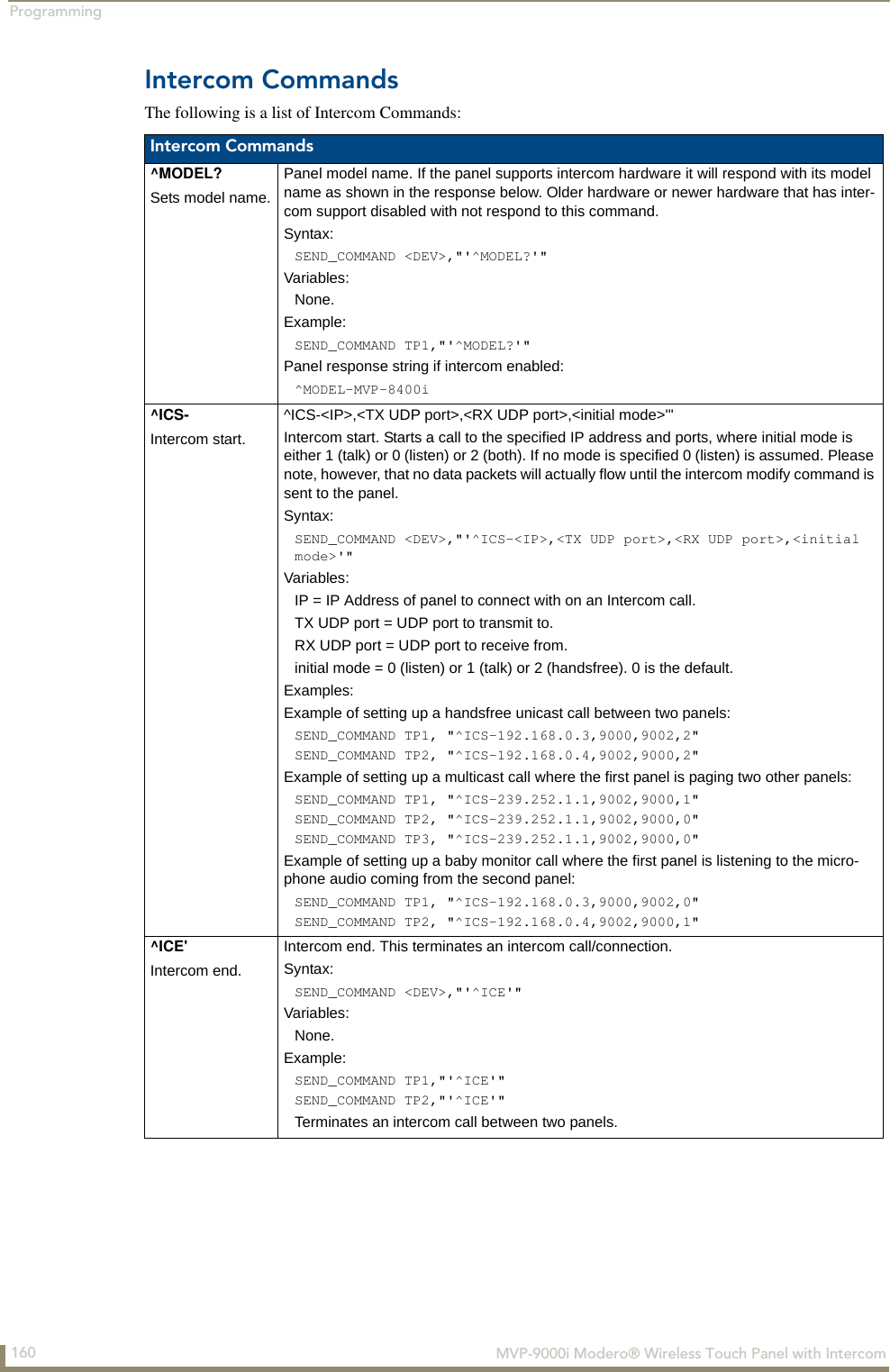
![Programming133MVP-9000i Modero® Wireless Touch Panel with Intercom "^" Button Commands (Cont.)^DPFDelete page flips from button if it already exists.Syntax:"'^DFP-<vt addr range>,<actions>,<page name>'"Variable: variable text address range = 1 - 4000.actions =Stan[dardPage] - Flip to standard pagePrev[iousPage] - Flip to previous pageShow[Popup] - Show Popup page Hide[Popup] - Hide Popup pageTogg[lePopup] - Toggle popup stateClearG[roup] - Clear popup page group from all pagesClearP[age] - Clear all popup pages from a page with the specified page nameClearA[ll] - Clear all popup pages from all pagespage name = 1 - 50 ASCII characters.Example:SEND COMMAND Panel,"'^DPF-409,Prev'"Deletes the assignment of a button from flipping to a previous page.^ENAEnable or disable buttons with a set variable text range.Syntax: "'^ENA-<vt addr range>,<command value>'"Variable: variable text address range = 1 - 4000.command value = (0= disable, 1= enable)Example:SEND_COMMAND Panel,"'^ENA-500.504&510.515,0'"Disables button pushes on buttons with variable text range 500-504 & 510-515.^FONSet a font to a specific Font ID value for those buttons with a defined address range.Font ID numbers are generated by the TPDesign4 programmers report.Syntax: "'^FON-<vt addr range>,<button states range>,<font value>'"Variable: variable text address range = 1 - 4000.button states range = 1 - 256 for multi-state buttons (0 = All states, for General buttons1 = Off state and 2 = On state).font value = range = 1 - XXX. Refer to the Default Font Styles and ID Numbers section on page 120.Example:SEND_COMMAND Panel,"'^FON-500.504&510.515,1&2,4'"Sets the font size to font ID #4 for the On and Off states of buttons with the variable text range of 500-504 & 510-515.The Font ID is generated by TPD4 and is located in TPD4 through the Main menu. Panel > Generate Programmer's Report >Text Only Format >Readme.txt.](https://usermanual.wiki/AMX/MVP9.Final-User-s-Manual/User-Guide-1376986-Page-148.png)
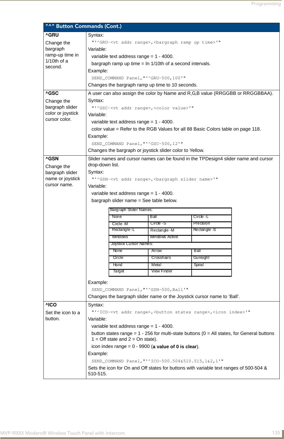
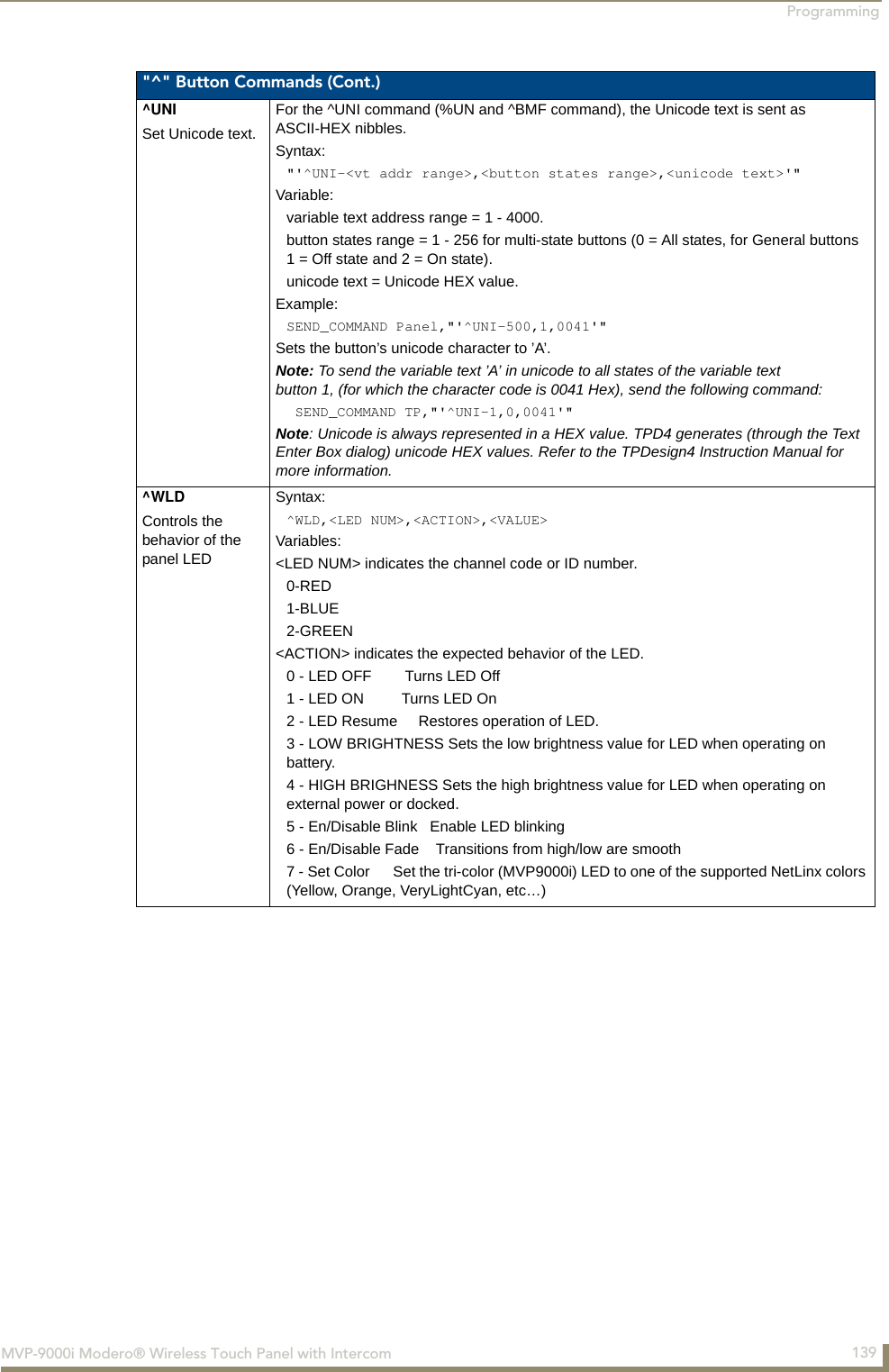
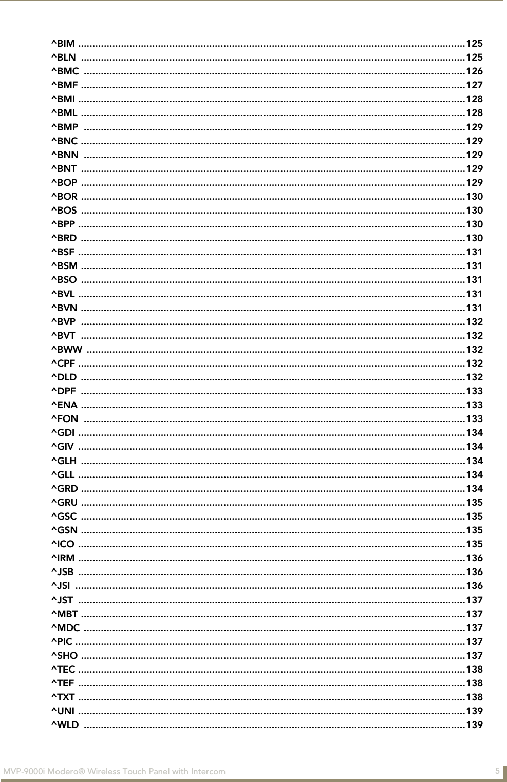
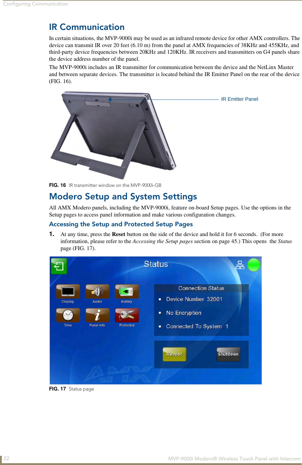
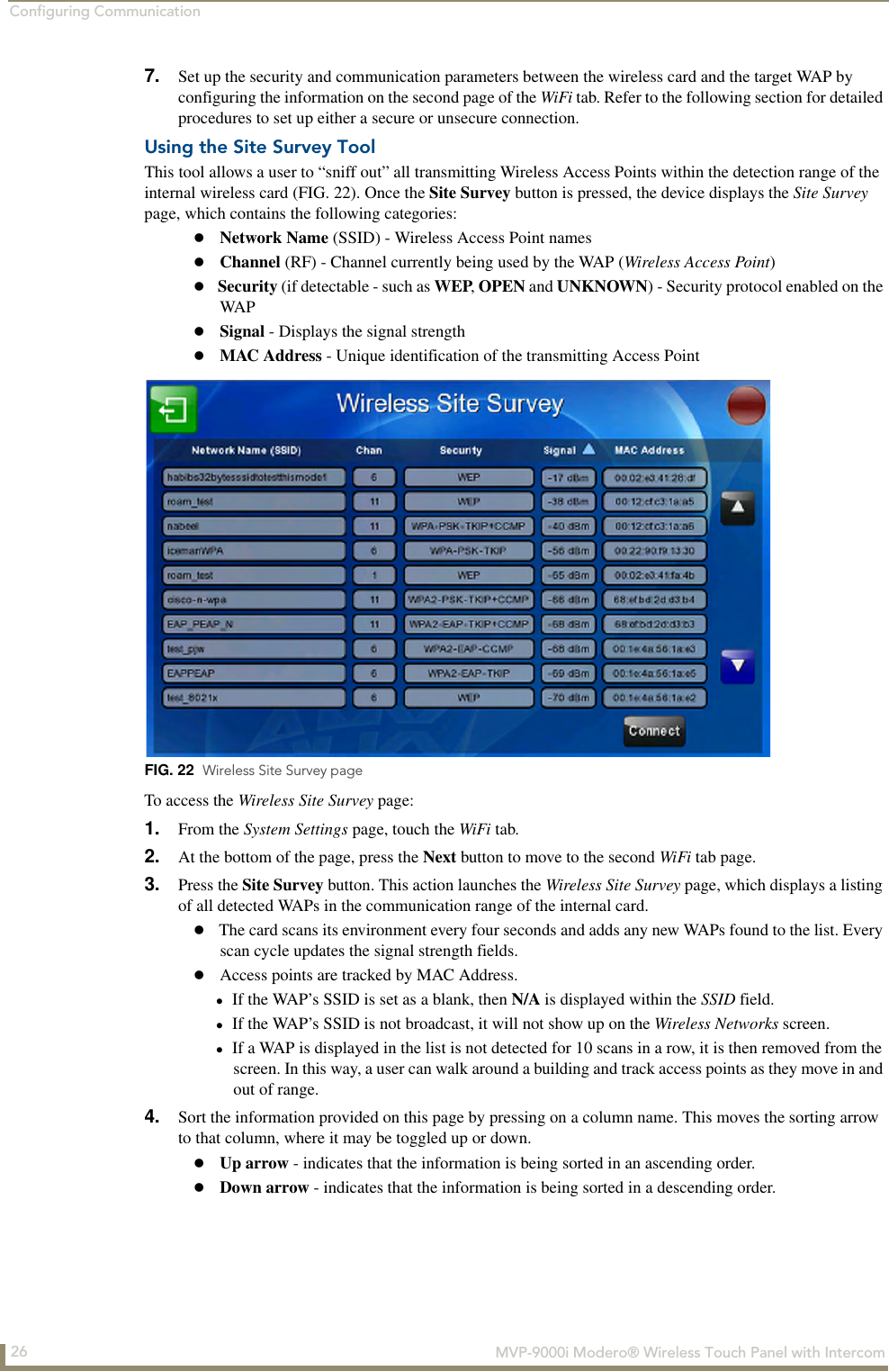
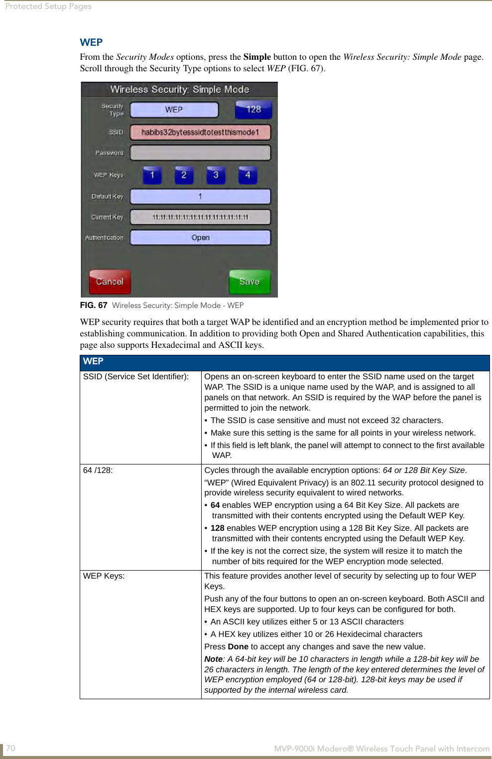
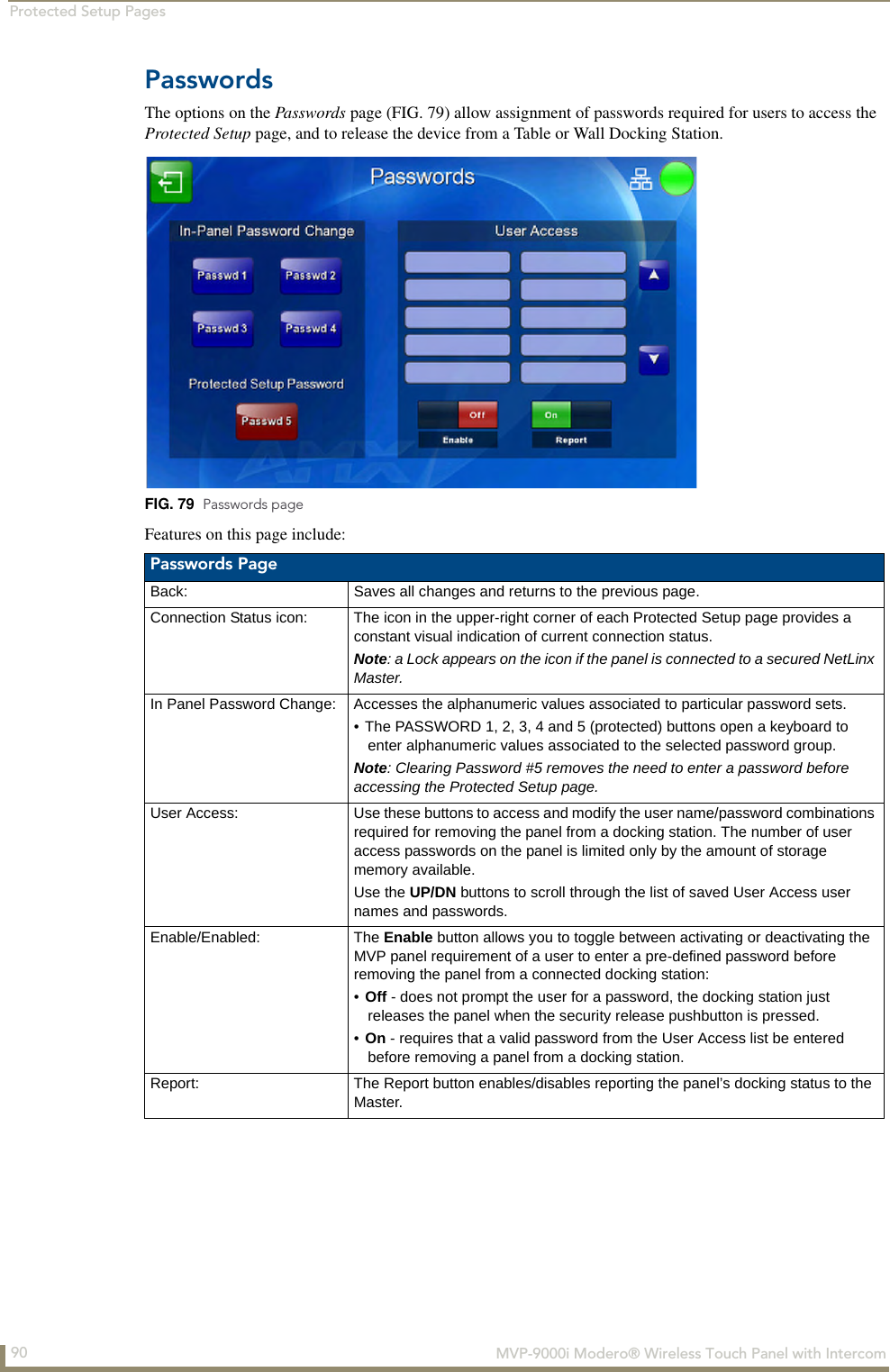
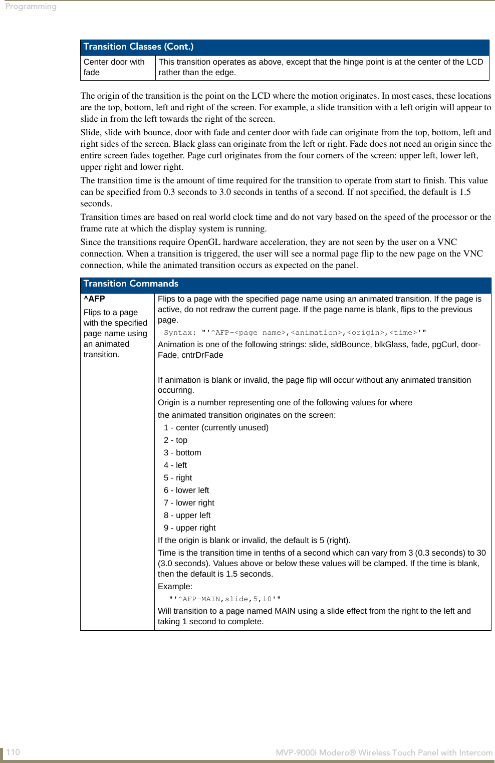
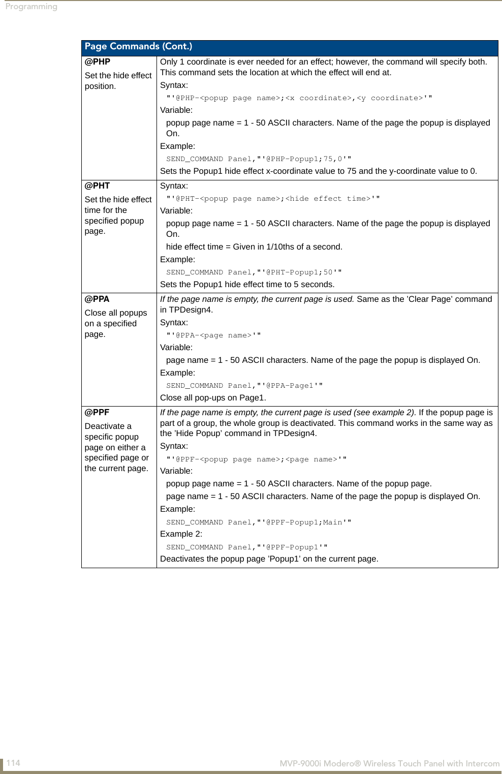
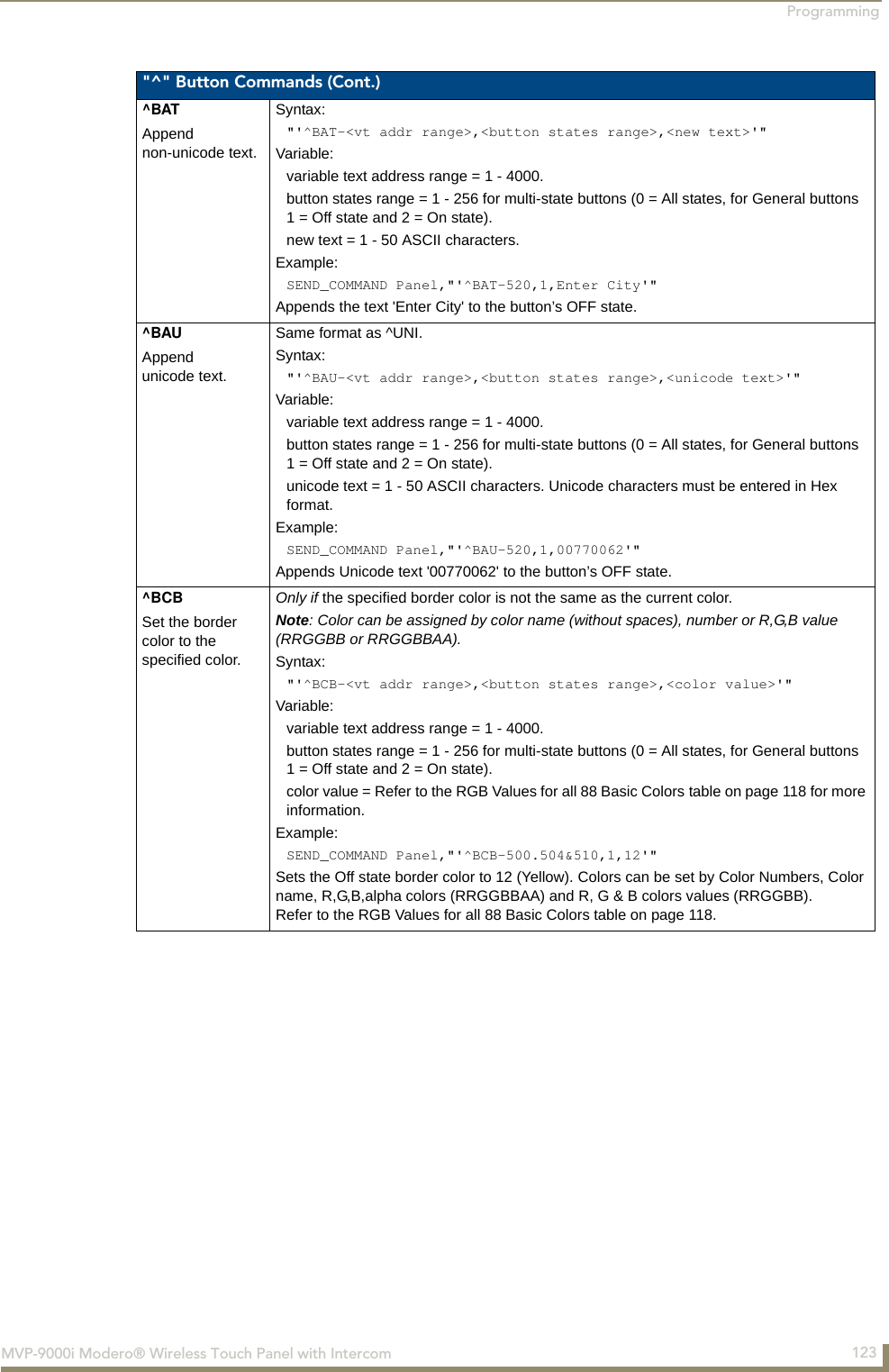
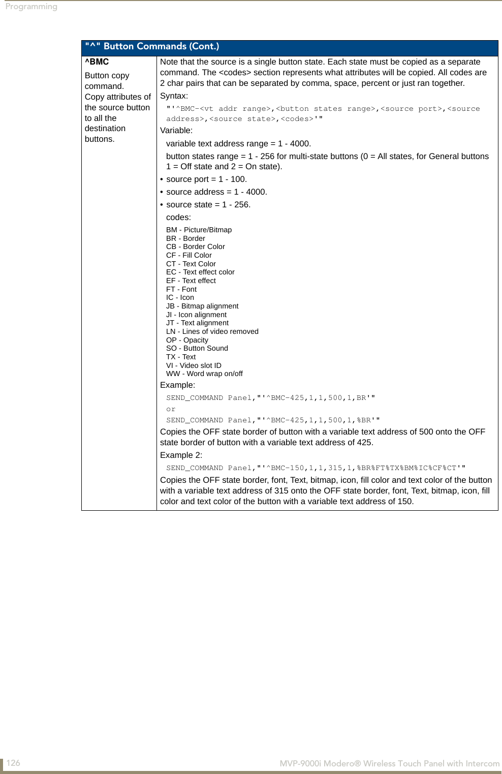
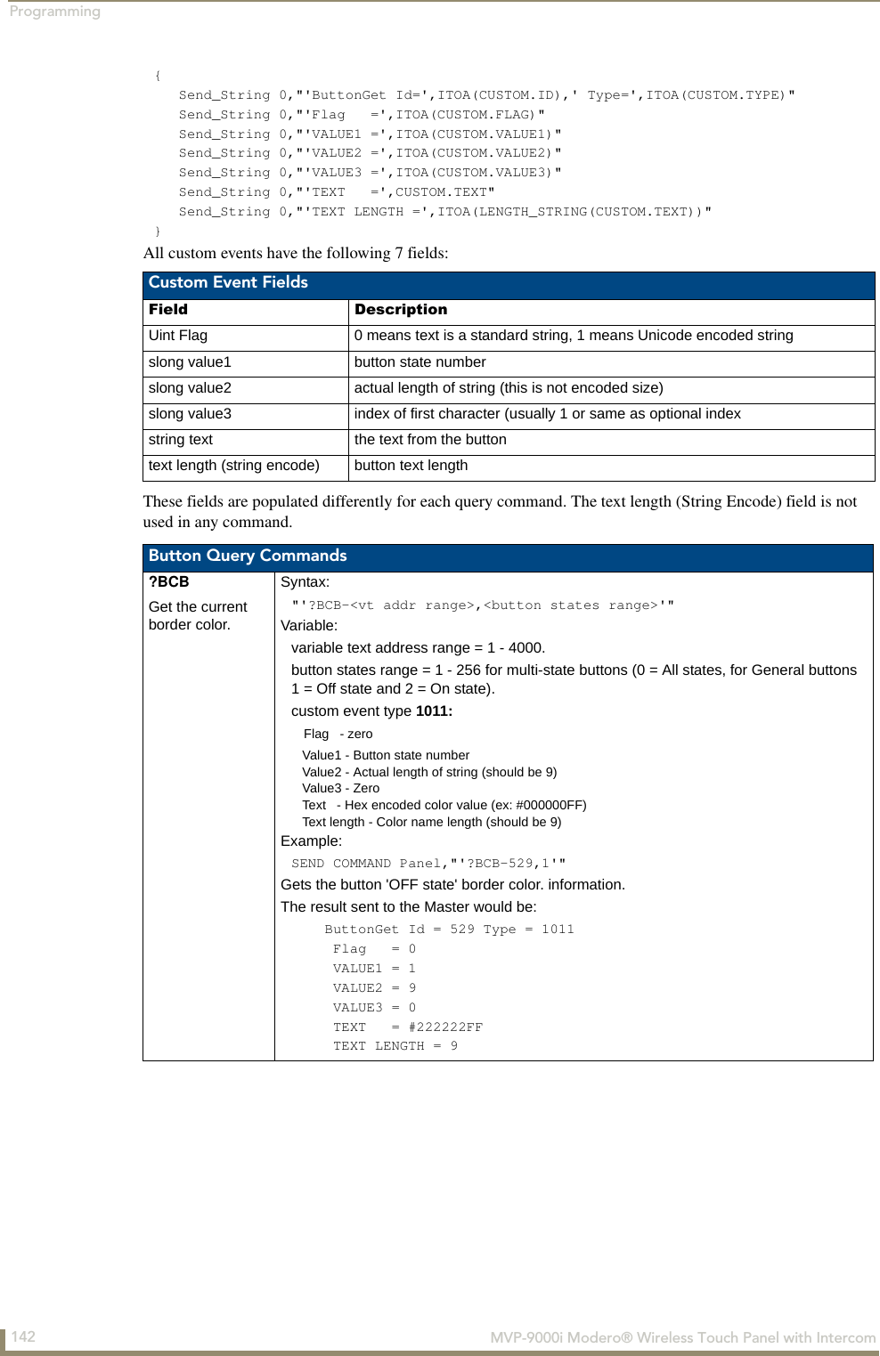
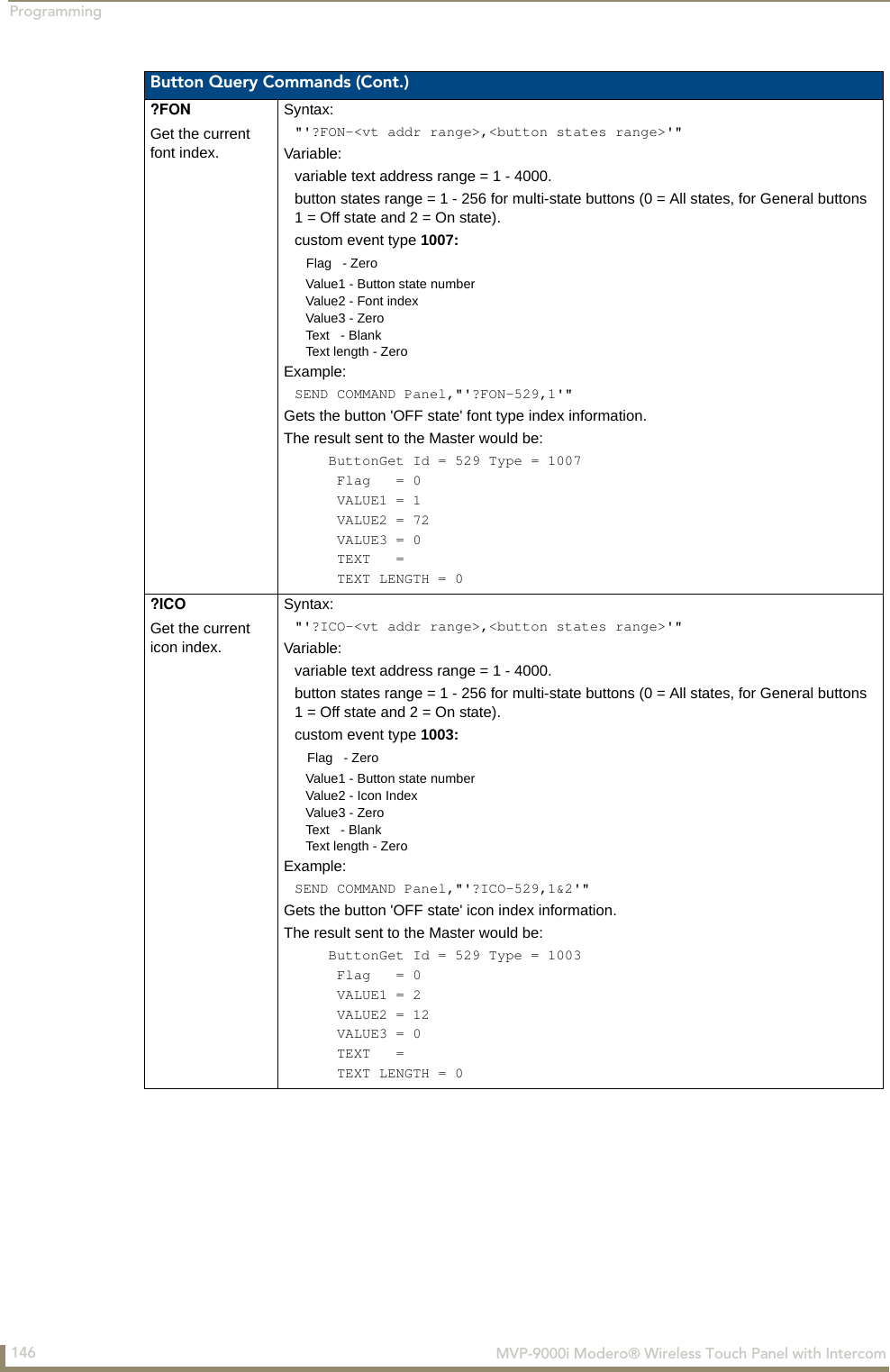
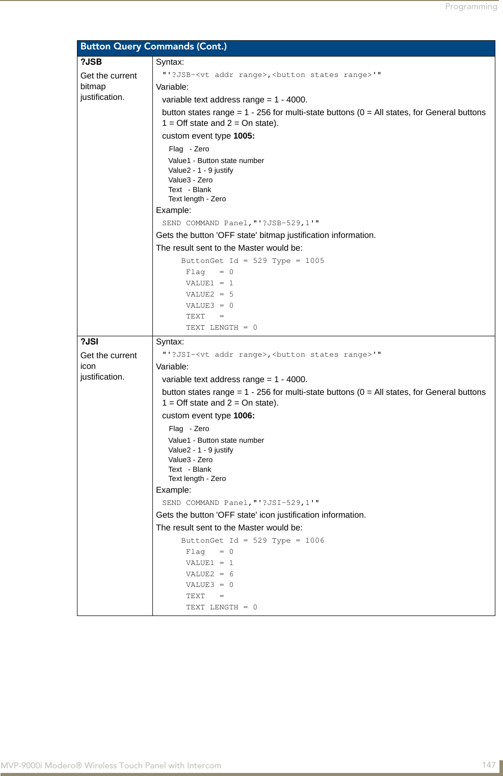
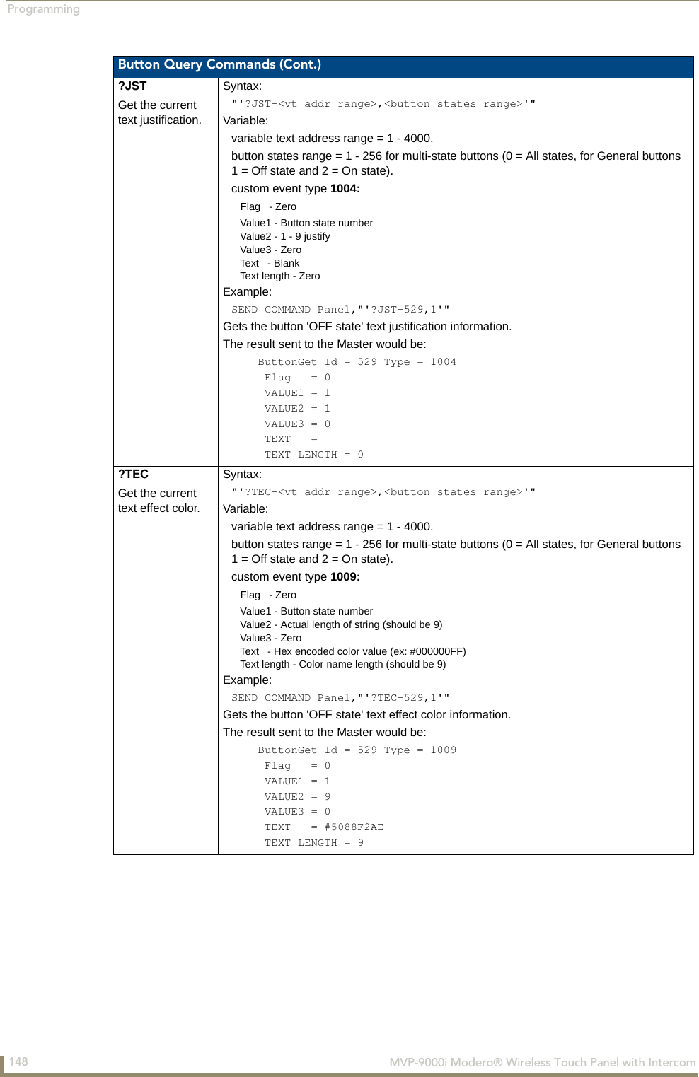
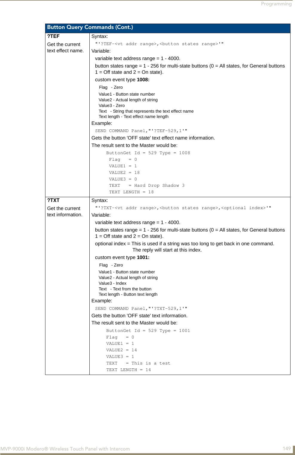
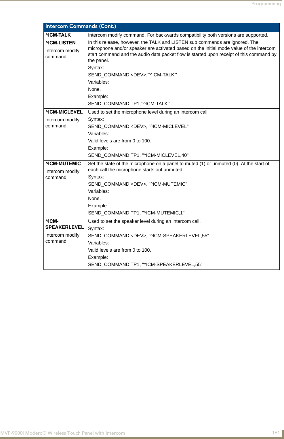
![Programming141MVP-9000i Modero® Wireless Touch Panel with IntercomText Effects NamesThe following is a listing of text effects names associated with the ^TEF command on page 138. Button Query CommandsButton Query commands reply back with a custom event. There will be one custom event for each button/state combination. Each query is assigned a unique custom event type. The following example is for debug purposes only:NetLinx Example: CUSTOM_EVENT[device, Address, Custom event type]DEFINE_EVENT CUSTOM_EVENT[TP,529,1001] // Text CUSTOM_EVENT[TP,529,1002] // Bitmap CUSTOM_EVENT[TP,529,1003] // Icon CUSTOM_EVENT[TP,529,1004] // Text Justification CUSTOM_EVENT[TP,529,1005] // Bitmap Justification CUSTOM_EVENT[TP,529,1006] // Icon Justification CUSTOM_EVENT[TP,529,1007] // Font CUSTOM_EVENT[TP,529,1008] // Text Effect Name CUSTOM_EVENT[TP,529,1009] // Text Effect Color CUSTOM_EVENT[TP,529,1010] // Word Wrap CUSTOM_EVENT[TP,529,1011] // ON state Border Color CUSTOM_EVENT[TP,529,1012] // ON state Fill Color CUSTOM_EVENT[TP,529,1013] // ON state Text Color CUSTOM_EVENT[TP,529,1014] // Border Name CUSTOM_EVENT[TP,529,1015] // OpacityText Effects• Glow -S • Medium Drop Shadow 1 • Hard Drop Shadow 1• Glow -M • Medium Drop Shadow 2 • Hard Drop Shadow 2• Glow -L • Medium Drop Shadow 3 • Hard Drop Shadow 3• Glow -X • Medium Drop Shadow 4 • Hard Drop Shadow 4• Outline -S • Medium Drop Shadow 5 • Hard Drop Shadow 5• Outline -M • Medium Drop Shadow 6 • Hard Drop Shadow 6• Outline -L • Medium Drop Shadow 7 • Hard Drop Shadow 7• Outline -X • Medium Drop Shadow 8 • Hard Drop Shadow 8• Soft Drop Shadow 1 • Medium Drop Shadow 1 with outline • Hard Drop Shadow 1 with outline• Soft Drop Shadow 2 • Medium Drop Shadow 2 with outline • Hard Drop Shadow 2 with outline• Soft Drop Shadow 3 • Medium Drop Shadow 3 with outline • Hard Drop Shadow 3 with outline• Soft Drop Shadow 4 • Medium Drop Shadow 4 with outline • Hard Drop Shadow 4 with outline• Soft Drop Shadow 5 • Medium Drop Shadow 5 with outline • Hard Drop Shadow 5 with outline• Soft Drop Shadow 6 • Medium Drop Shadow 6 with outline • Hard Drop Shadow 6 with outline• Soft Drop Shadow 7 • Medium Drop Shadow 7 with outline • Hard Drop Shadow 7 with outline• Soft Drop Shadow 8 • Medium Drop Shadow 8 with outline • Hard Drop Shadow 8 with outline• Soft Drop Shadow 1 with outline• Soft Drop Shadow 2 with outline• Soft Drop Shadow 3 with outline• Soft Drop Shadow 4 with outline• Soft Drop Shadow 5 with outline• Soft Drop Shadow 6 with outline• Soft Drop Shadow 7 with outline• Soft Drop Shadow 8 with outline](https://usermanual.wiki/AMX/MVP9.Final-User-s-Manual/User-Guide-1376986-Page-156.png)
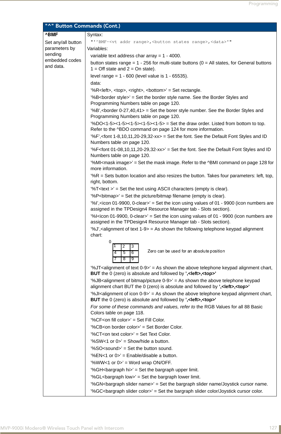
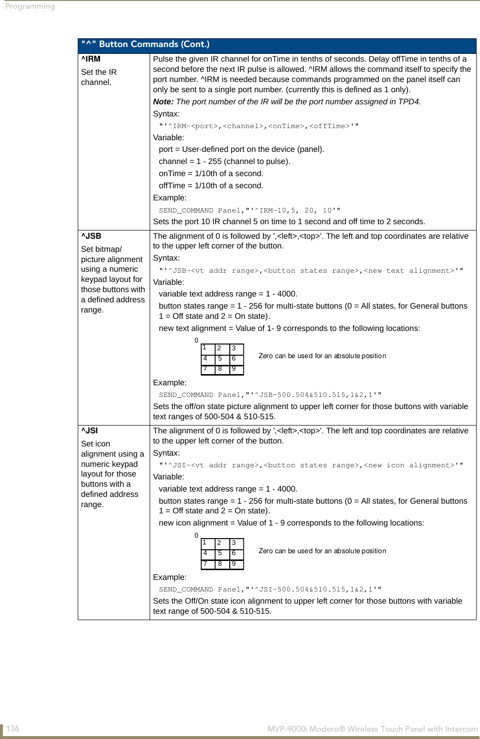
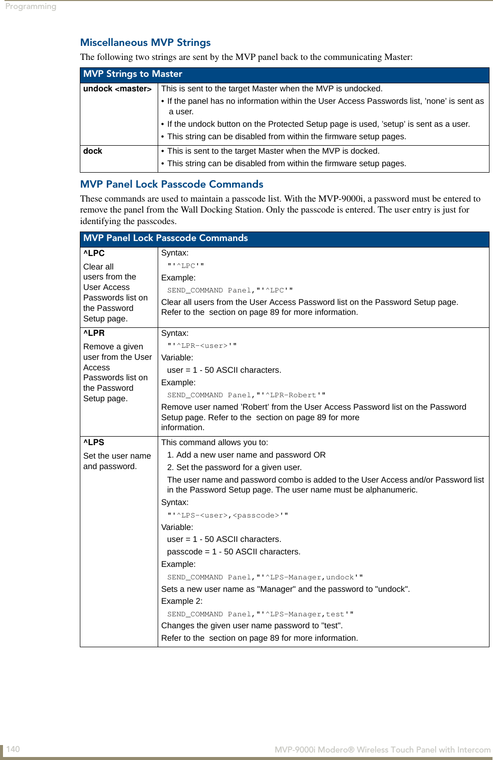
![Appendix A: Text Formatting174 MVP-9000i Modero® Wireless Touch Panel with IntercomText Area Input MaskingText Area Input Masking may be used to limit the allowed/correct characters that are entered into a text area. For example, in working with a zip code, a user could limit the entry to a max length of only 5 characters; with input masking, this limit could be changed to 5 mandatory numerical digits and 4 optional numerical digits. A possible use for this feature is to enter information into form fields. The purpose of this feature is to: With this feature, it is not necessary to: Input mask character types These character types define what information is allowed to be entered in any specific instance. The following table lists what characters in an input mask will define what characters are allowed in any given position. Refer to the following SEND_COMMANDs for more detailed information: • Force the use of correct type of characters (i.e. numbers vs. characters)• Limit the number of characters in a text area• Suggest proper format with fixed characters• Right to Left• Required or Optional• Change/Force a Case• Create multiple logical fields• Specify range of characters/number for each field• Limit the user to a choice of selections• Handle complex input tasks such as names, days of the week, or month by name• Perform complex validation such as Subnet Mask validationCharacter TypesCharacter Masking Rule0 Digit (0 to 9, entry required, plus [+] and minus [-] signs not allowed)9 Digit or space (entry not required, plus and minus signs not allowed)# Digit or space (entry not required; plus and minus signs allowed)L Letter (A to Z, entry required)? Letter (A to Z, entry optional)A Letter or digit (entry required)a Letter or digit (entry optional)& Any character or a space (entry required)C Any character or a space (entry optional)The number of the above characters used determines the length of the input masking box. Example: 0000 requires an entry, requires digits to be used, and allows only 4 characters to be entered/used.•^BIM - Sets the input mask for the specified addresses. (see the ^BIM section on page 125).•^BMF subcommand %MK - sets the input mask of a text area (see the ^BMF section on page 127).](https://usermanual.wiki/AMX/MVP9.Final-User-s-Manual/User-Guide-1376986-Page-189.png)
![Appendix A: Text Formatting175MVP-9000i Modero® Wireless Touch Panel with IntercomInput Mask Ranges These ranges allow a user to specify the minimum and maximum numeric value for a field. Only one range is allowed per field. Using a range implies a numeric entry ONLY. An example from the above table: [0|255] This allows a user to enter a value from 0 to 255.Input mask next field characters These characters allow you to specify a list of characters that cause the keyboard to move the focus to the next field when pressed, instead of inserting the text into the text area. An example from the above table: {.} or {:} or {.:} Proceed to the next text area input box after a user hits any of these keys.Input mask operationsInput Mask Operators change the behavior of the field in the following way: Input mask literalsTo define a literal character, enter any character, other than those shown in the above table (including spaces, and symbols). A back-slash ('\') causes the character that follows it to be displayed as the literal character. For example, \A is displayed just as the letter A. To define one of the following characters as a literal character, precede that character with a back-slash. Text entry operation using Input Masks.A keyboard entry using normal text entry is straightforward. However, once an input mask is applied, the behavior of the keyboard needs to change to accommodate the input mask's requirement. When working with masks, any literal characters in the mask will be "skipped" by any cursor movement, including cursor, backspace, and delete keys.When operating with a mask, the mask should be displayed with placeholders. The "-" character should display where you should enter a character. The arrow keys will move between the "-" characters and allow you to replace them. The text entry code operates as if it is in the overwrite mode. If the cursor is positioned on a character already entered and you type in a new (and valid) character, the new character replaces the old character. There is no shifting of characters.When working with ranges specified by the [] mask, the keyboard allows you to enter a number between the values listed in the ranges. If a user enters a value that is larger than the maximum, the maximum number of right-most characters is used to create a new, acceptable value. Example 1: If you type "125" into a field accepting 0-100, then the values displayed will be "1", "12", "25". Example 2: If the max for the field was 20, then the values displayed will be "1", "12", "5".Input Mask RangesCharacter Meaning[ Start range] End range| Range SeparatorInput Mask Next Field CharCharacter Meaning{ Start Next Field List} End Next Field ListInput Mask OperatorsCharacter Meaning< Forces all characters to be converted to lowercase> Forces all characters to be converted to uppercase^ Sets the overflow flag for this field](https://usermanual.wiki/AMX/MVP9.Final-User-s-Manual/User-Guide-1376986-Page-190.png)
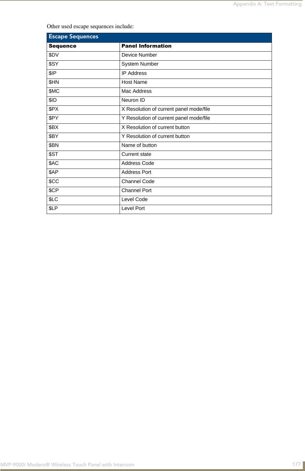
![Appendix A: Text Formatting176 MVP-9000i Modero® Wireless Touch Panel with IntercomWhen data overflows from a numerical field, the overflow value is added to the previous field on the chain if the overflow character was specified. In the above example, if the overflow flag was set, the first example will place the "1" into the previous logical field and the second example will place "12" in the previous logical field. If the overflow field already contains a value, the new value will be inserted to the right of the current characters and the overflow field will be evaluated. Overflow continues to work until a field with no overflow value is set or no more fields remain (i.e. reached first field).If a character is typed and that character appears in the Next Field list, the keyboard should move the focus to the next field. For example, when entering time, a ":" is used as a next field character. If you enter "1:2", the 1 is entered in the current field (hours) and then the focus is moved to the next field and 2 is entered in that field.When entering time in a 12-hour format, entry of AM and PM is required. Instead of adding AM/PM to the input mask specification, the AM/PM should be handled within the NetLinx code. This allows a programmer to show/hide and provide discrete feedback for AM and PM.Input mask output examplesThe following are some common input masking examples: URL ResourcesA URL can be broken into several parts. For example, with the URL http://www.amx.com/company-info-home.asp, this URL indicates that the protocol in use is http (HyperText Transport Protocol) and that the information resides on a host machine named www.amx.com. The image on that host machine is given an assignment (by the program) name of company-info-home.asp (Active Server Page). The exact meaning of this name on the host machine is both protocol dependent and host dependent. The information normally resides in a file, but it could be generated dynamically. This component of the URL is called the file component, even though the information is not necessarily in a file. A URL can optionally specify a port, which is the port number to which the TCP/IP connection is made on the remote host machine. If the port is not specified, the default port for the protocol is used instead. For example, the default port for http is 80. An alternative port could be specified as: http://www.amx.com:8080/company-info-home.asp.Special Escape SequencesThe system has only a limited knowledge of URL formats, as it transparently passes the URL information onto the server for translation. A user can then pass any parameters to the server side programs such as CGI scripts or active server pages. However; the system will parse the URL looking for special escape codes. When it finds an escape code, it replaces that code with a particular piece of panel, button, or state information. For example, "http://www.amx.com/img.asp?device=$DV" would become http://www.amx.com/img.asp?device=10001. Output ExamplesCommon Name Input Mask InputIP Address Quad [0|255]{.} Any value from 0 to 255Hour [1|12]{:} Any value from 1 to 12Minute/Second [0|59]{:} Any value from 0 to 59Frames [0|29]{:} Any value from 0 to 29Phone Numbers (999) 000-0000 (555) 555-5555Zip Code 00000-9999 75082-4567Any legal HTTP syntax can be used.](https://usermanual.wiki/AMX/MVP9.Final-User-s-Manual/User-Guide-1376986-Page-191.png)