ARRIS BGW210 BGW210-700 ARRIS uDSL Wireless Residential Gateway User Manual Install and Operations Guide
ARRIS BGW210-700 ARRIS uDSL Wireless Residential Gateway Install and Operations Guide
UserManual.wiki
>
ARRIS
>
BGW210 User Manual
User Manual
Navigation menu
Upload a User Manual
Namespaces
Wiki Guide
HTML
PDF
Info
Views
User Manual
Discussion / Help
Navigation
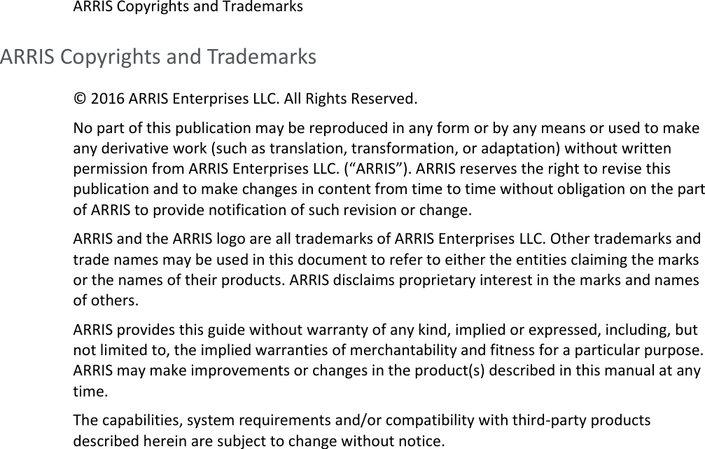
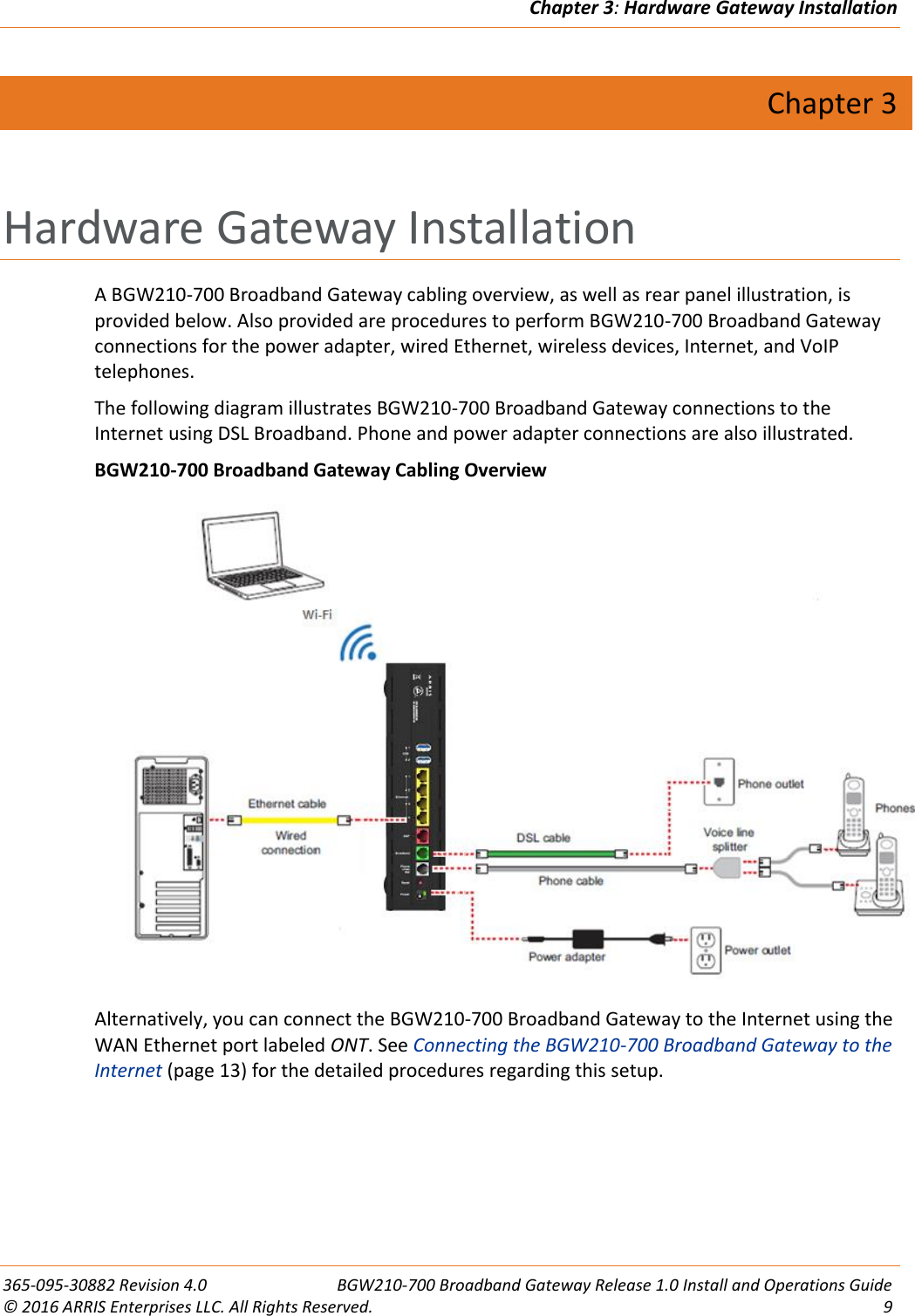
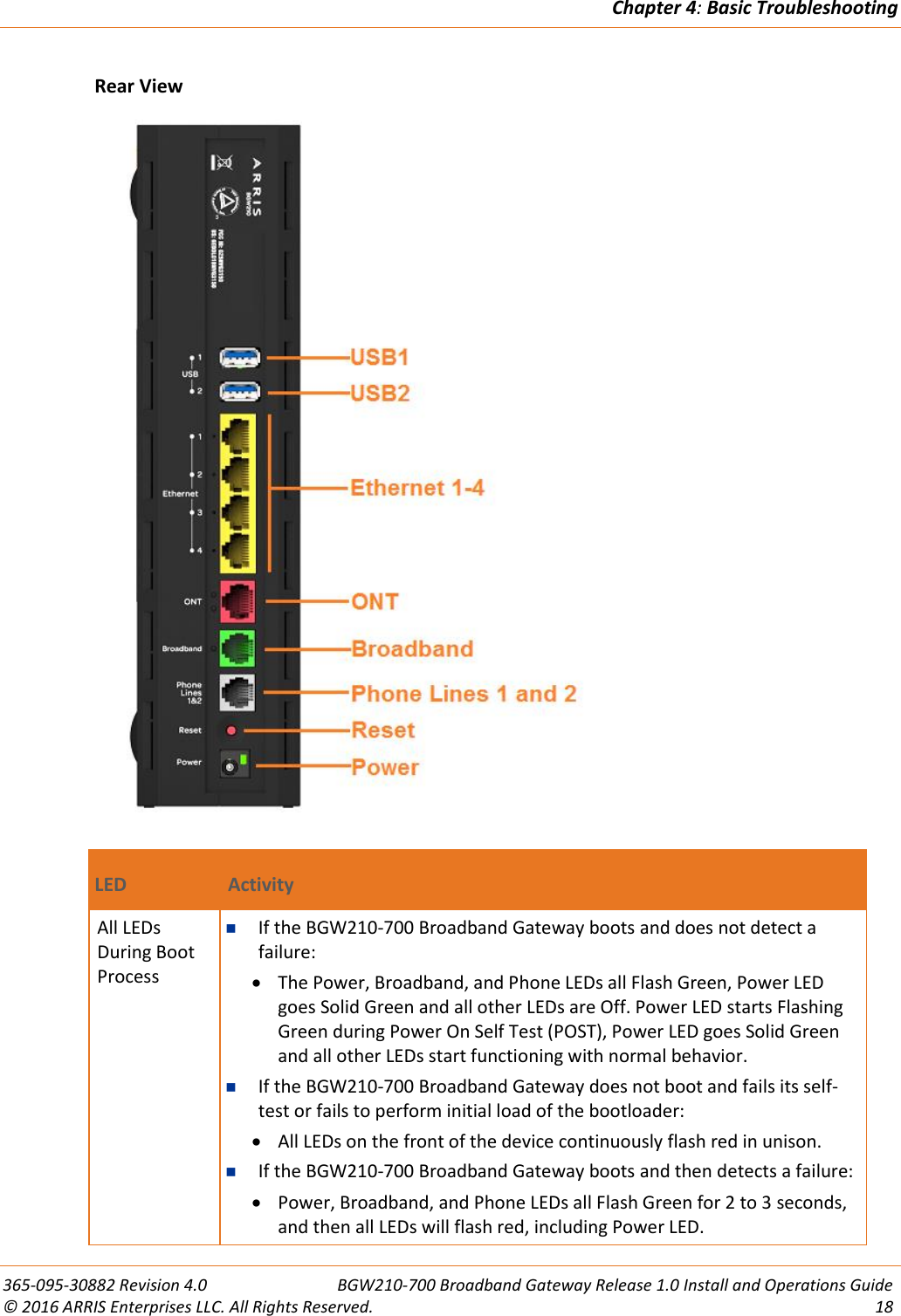
![Chapter 6: Important Safety Instructions 365-095-30882 Revision 4.0 BGW210-700 Broadband Gateway Release 1.0 Install and Operations Guide © 2016 ARRIS Enterprises LLC. All Rights Reserved. 29 1. The Federal Communications Commission (FCC) has established Rules, which permit this device to be directly connected to the telephone network. Standardized jacks are used for these connections. This equipment should not be used on party lines or coin phones. 2. If this device is malfunctioning, it may also be causing harm to the telephone network; this device should be disconnected until the source of the problem can be determined and until repair has been made. If this is not done, the telephone company may temporarily disconnect service. 3. The telephone company may make changes in its technical operations and procedures; if such changes affect the compatibility or use of this device, the telephone company is required to give adequate notice of the changes. You will be advised of your right to file a complaint with the FCC. 4. If the telephone company requests information on what equipment is connected to their lines, inform them of: The telephone number to which this unit is connected. The ringer equivalence number. [0.XB] (Indicated on the label) The USOC jack required. [RJ11C] The FCC Registration Number. [US:AAAEQ##TXXXX] (Indicated on the label) The Ringer Equivalence Number (REN) is used to determine how many devices can be connected to your telephone line. In most areas, the sum of the REN's of all devices on any one line should not exceed five (5.0). If too many devices are attached, they may not ring properly. FCC Caution Caution: Any changes or modifications not expressly approved by the party responsible for compliance could void the user’s authority to operate this equipment. This transmitter must not be co-located or operating in conjunction with any other antenna or transmitter. Radiation Exposure Statement This equipment complies with FCC radiation exposure limits as set forth for an uncontrolled environment. This equipment should be installed and operated maintaining a minimum distance of 22 cm (9 inches) between the device and your body.](https://usermanual.wiki/ARRIS/BGW210/User-Guide-3205200-Page-29.png)