Aclara Technologies 9975T Aclara Synergize RF Network DCU XCVR User Manual COVER SHEET FOR ASSEMBLY PROCEDURES
Aclara Technologies LLC Aclara Synergize RF Network DCU XCVR COVER SHEET FOR ASSEMBLY PROCEDURES
Contents
- 1. Users Manual
- 2. Label Instruction
- 3. User Manual
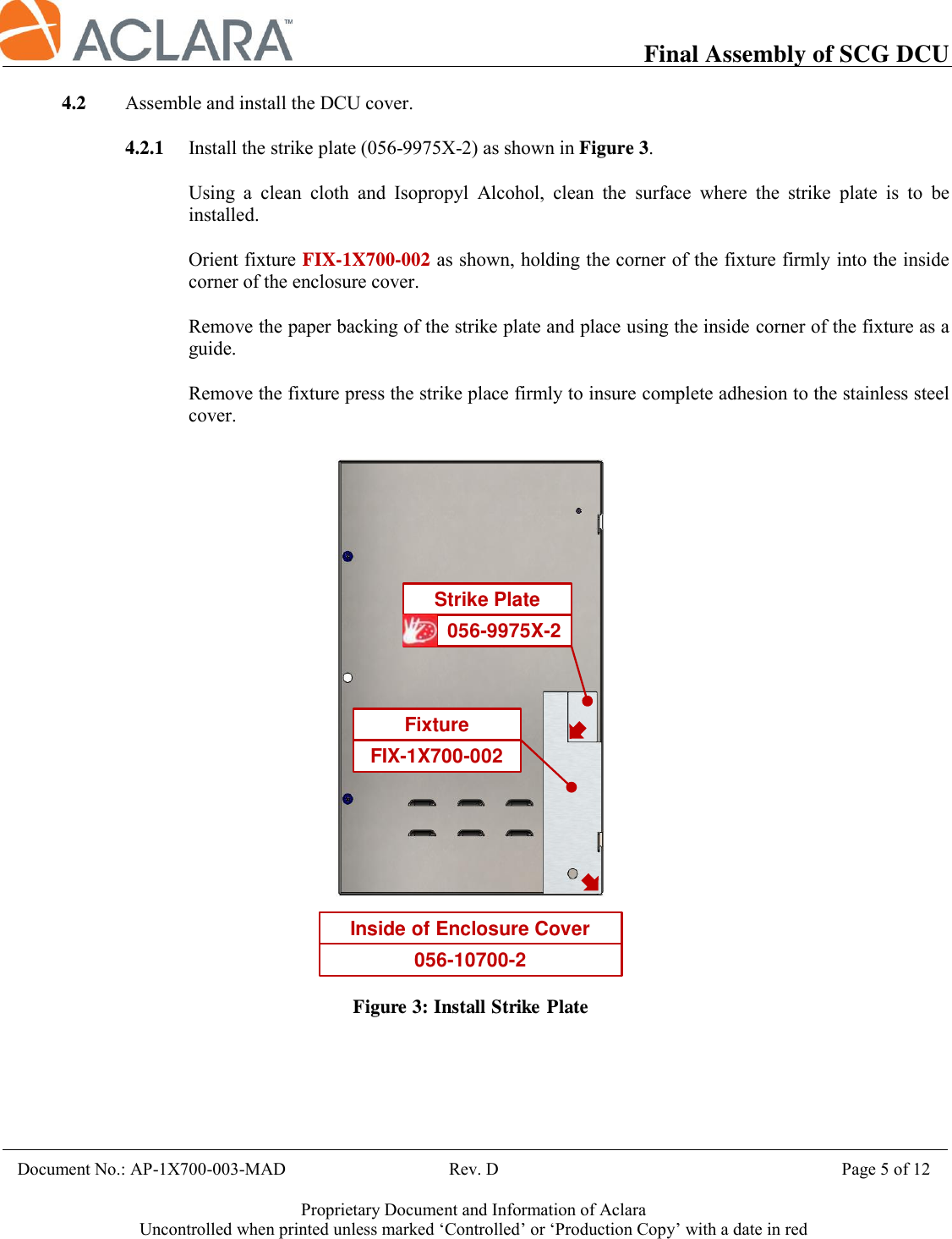
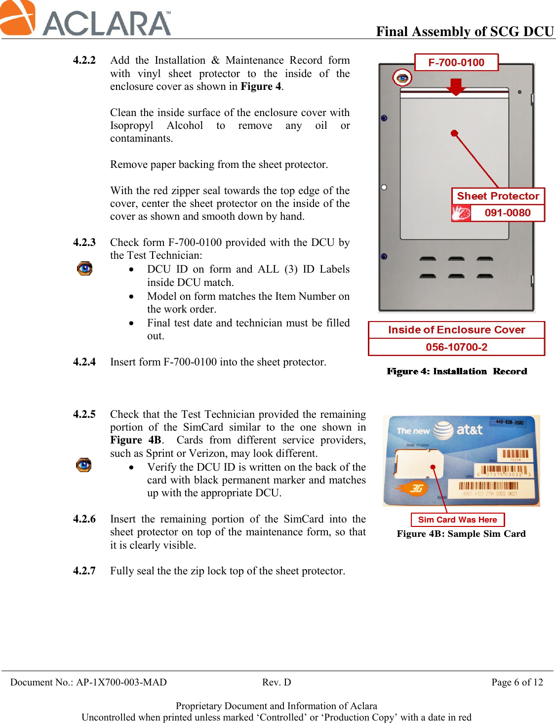
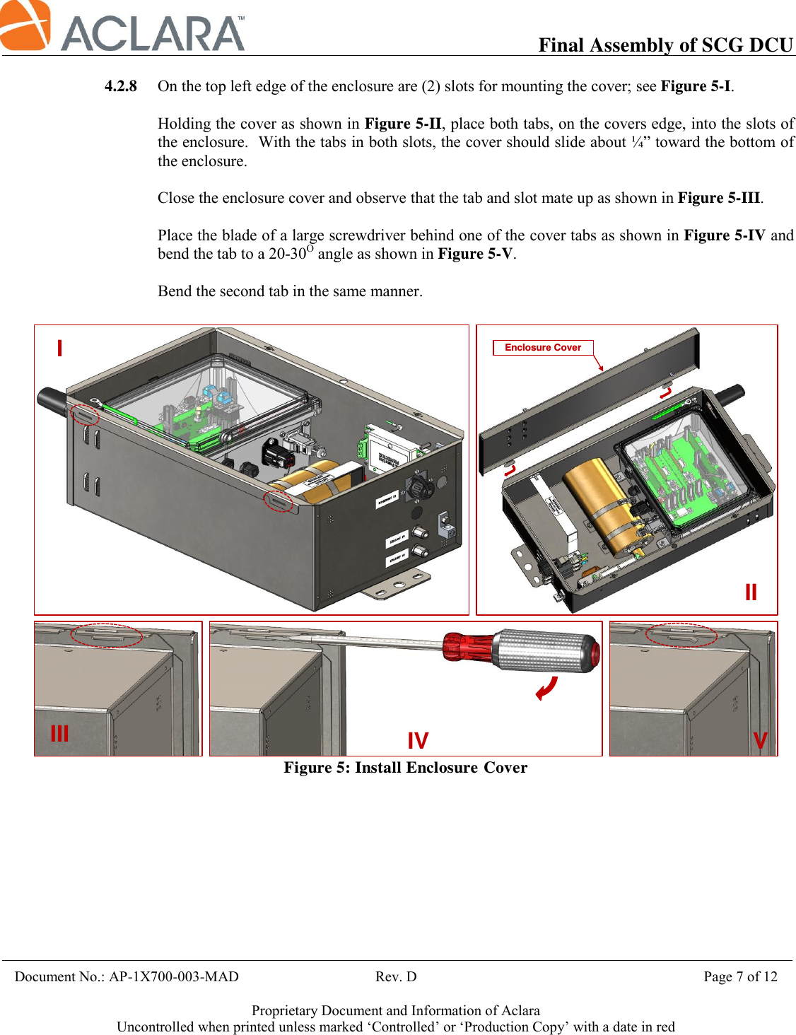
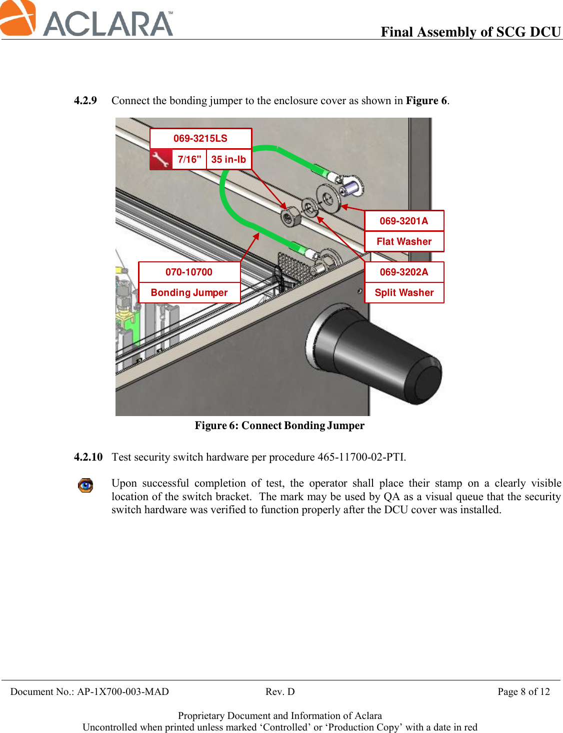
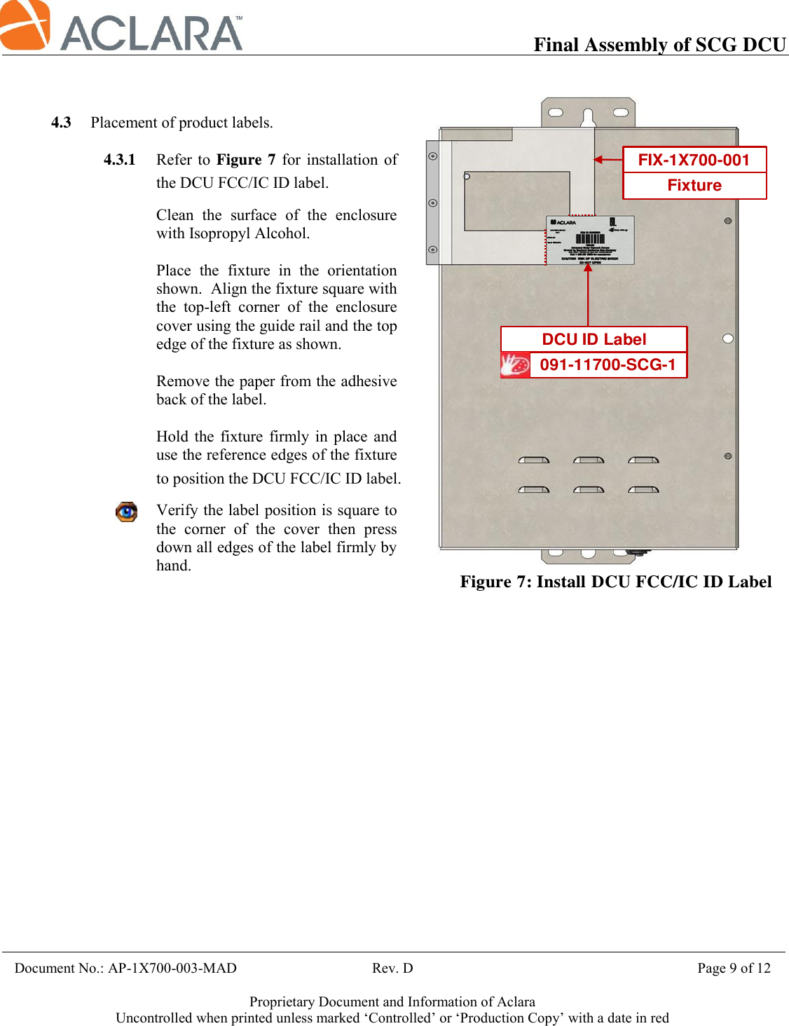
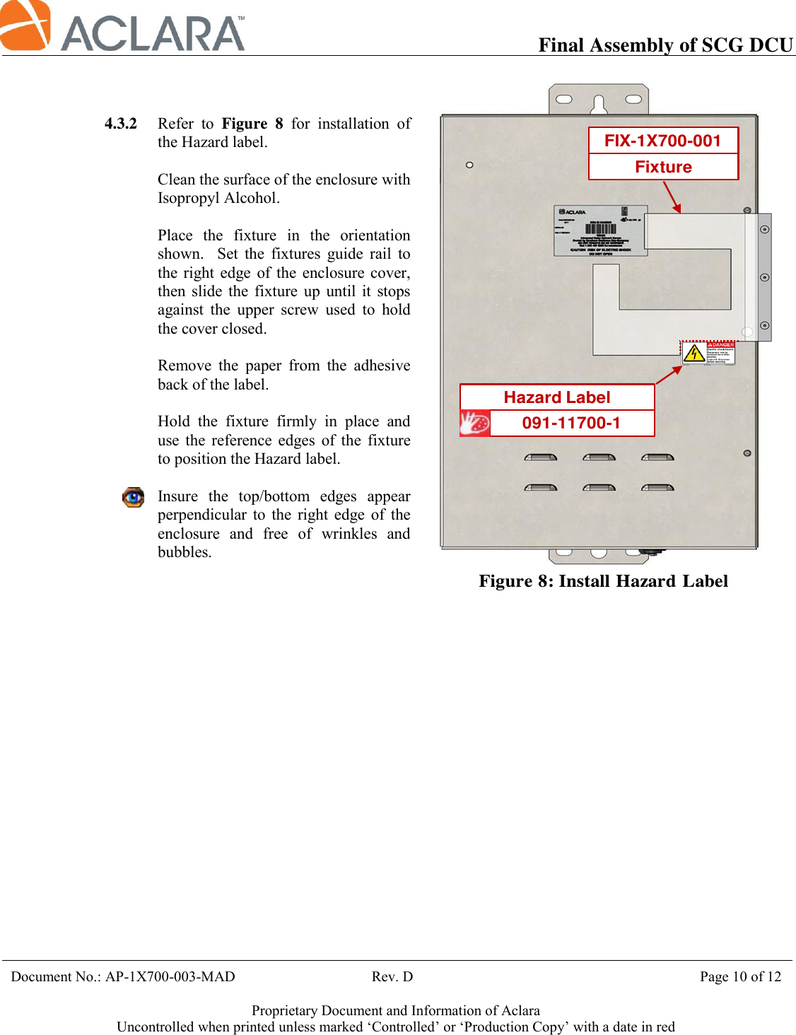
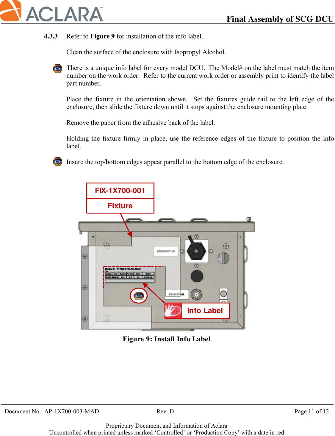
Label Instruction