Advanced RF Technologies AXM1900-9543I Repeater User Manual Epoch H ICS
Advanced RF Technologies, Inc. Repeater Epoch H ICS
UserManual.wiki
>
Advanced RF Technologies
>
AXM1900 9543I User Manual
User Manual
Navigation menu
Upload a User Manual
Namespaces
Wiki Guide
HTML
PDF
Info
Views
User Manual
Discussion / Help
Navigation
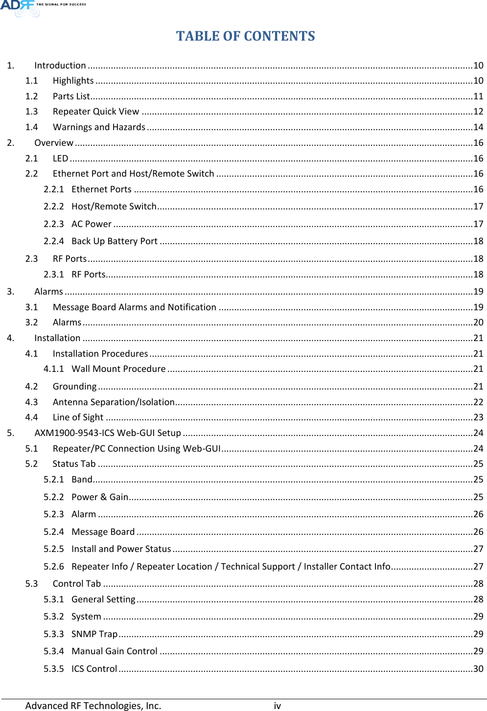

![3. ALARMS 3.1 Message Board Alarms and Notification Table 3-1 Message Board Alarms and Notification Parameters Remark AC Fail Power supply is not operating within specs DC Fail Power supply is not operating within specs Fan[1/2] Fail System has detected an issue with the fan1 and fan2 Temperature Module is above the normal operating temperature Current Power supply is not operating within specs System Halt System is in a shutdown state due to a hard fail alarm DSP Fault System has detected an issue with the internal DSP chip OSC Oscillation detected DL Signal not detected DL signal is below the specified level DL Signal Low DL signal is below the specified level Input Overload Incoming in-band DL or UL signal is too strong Out of band Overload Incoming out-band DL or UL signal is too strong Synthesizer Lock Fail Issue with internal PLL DL RF Power Input + gain does not match the output level (above delta of 6 dB) Overpower Output level is above the max output levels VSWR Power is being reflected back to the repeater Heartbeat Heartbeat Reboot Reboot Factory setting Factory setting Door Door alarm set/clear. Advanced RF Technologies, Inc. 19](https://usermanual.wiki/Advanced-RF-Technologies/AXM1900-9543I/User-Guide-2259931-Page-19.png)
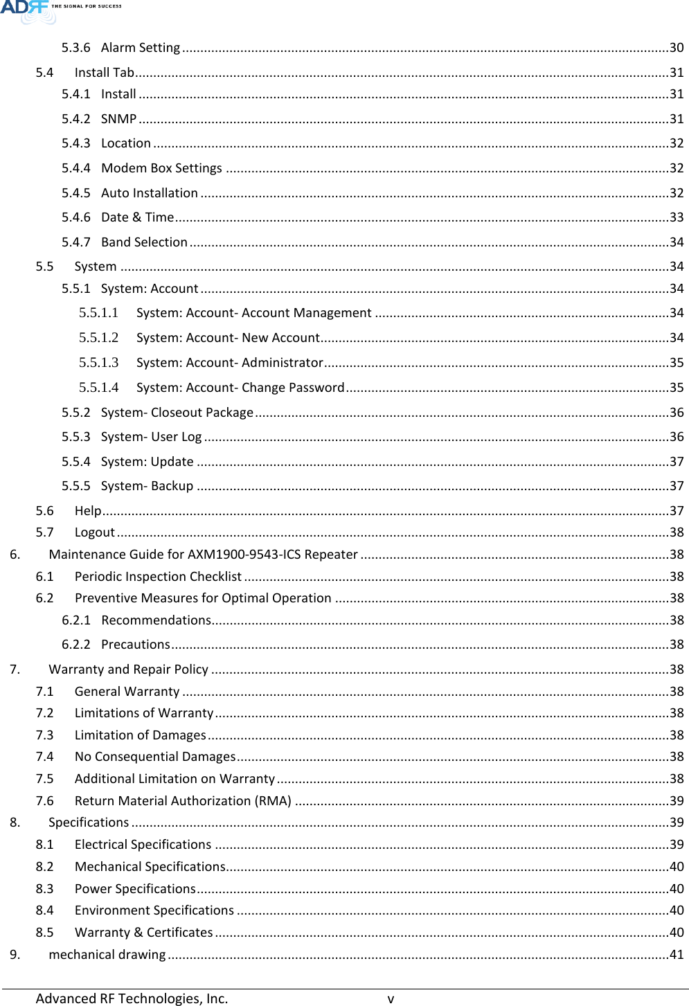
![3.2 Alarms Table 3-2 Alarms Threshold Parameters Remark AC Fail Power supply is not operating within specs. (4 seconds) DC Fail Power supply is not operating within specs. (4 seconds) Fan1, Fan2 Fail System has detected an issue with each fan. (4 seconds) Temperature Module is above the normal operating temperature. (4 seconds) Over Temperature [ Soft: 80~87 C, Hard: Above 87 C] Current Power supply is not operating within specs. (4 Second) Over Current [ Hard: Above 20A] System Halt System is in a shutdown state due to a hard fail alarm. (10 times) DSP Fault System has detected an issue with the internal DSP chip. (Cannot communication with DSP) OSC Oscillation detected. Alarm is only present when one-time oscillation check is performed. DL Signal not detected DL signal is below the specified level. (default: -90dBm, 4 seconds) DL Signal Low DL signal is below the specified level. (default: -85dBm, 4 seconds) Input Overload Input signal is above the threshold. (4 seconds) (Soft: DL -10dBm/UL -12dBm, Hard: DL -8dBm/UL -10dBm) Out of band Overload Out of band signal is above the threshold. (4 seconds) (Soft: DL -10dBm/UL -12dBm, Hard: DL -8dBm/UL -10dBm) Synthesizer Lock Fail Issue with internal PLL(4 seconds) DL RF Power Input + gain does not match the output level (default delta of 6 dB) Overpower Output level is above the max output levels AGC On case(Soft: AGC Level+ 1~2dB, Hard: AGC Level + >2dB) AGC Off case(Soft: max output level+ 1~2dB, Hard: max output level + >2dB) VSWR Power is being reflected back to the repeater. Threshold = output power - 8dB. For example, if the repeater is outputting 24dBm, then if the system detects 16dBm of return power, then the VSWR will be triggered.(Triggered in case of over +15dBm output power) Door Door alarm set : Door open Door alarm clear : Door close Advanced RF Technologies, Inc. 20](https://usermanual.wiki/Advanced-RF-Technologies/AXM1900-9543I/User-Guide-2259931-Page-20.png)
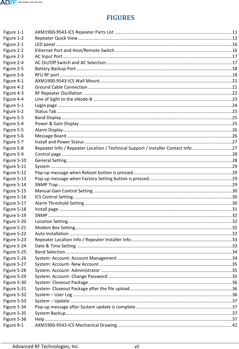
![• Input [dBm] – Displays the in-band Downlink/Uplink signal level. The system will display “--.-“when the input level is < -90 dBm. • Gain [dB] - User Set: Displays the amount of gain that user set. - ALC: Displays the amount of gain that is attenuated by ALC function. - ILC: Displays the amount of gain that is attenuated by ILC function. - Actual: Displays the actual amount of gain that is currently in use. • Output [dB] – Displays the Downlink/Uplink output power levels. The system will display “--.-“ when the output level is < +5 dBm. • Isolation [dB] – Displays the measured isolation value. The value inside of the parenthesis is the “actual gain - measured isolation value”. When the “actual gain – measured isolation value” is less than -15dB, then “MAX” will be displayed. 5.2.3 Alarm This section displays the alarm status for System alarms, RF Alarms, and Power alarms. If an alarm is present in the system, then the color of the alarm tab will change according to the type of failure. Figure 5-5 Alarm Display 5.2.4 Message Board Displays the 40 most recent events. Figure 5-6 Message Board Advanced RF Technologies, Inc. 26](https://usermanual.wiki/Advanced-RF-Technologies/AXM1900-9543I/User-Guide-2259931-Page-26.png)
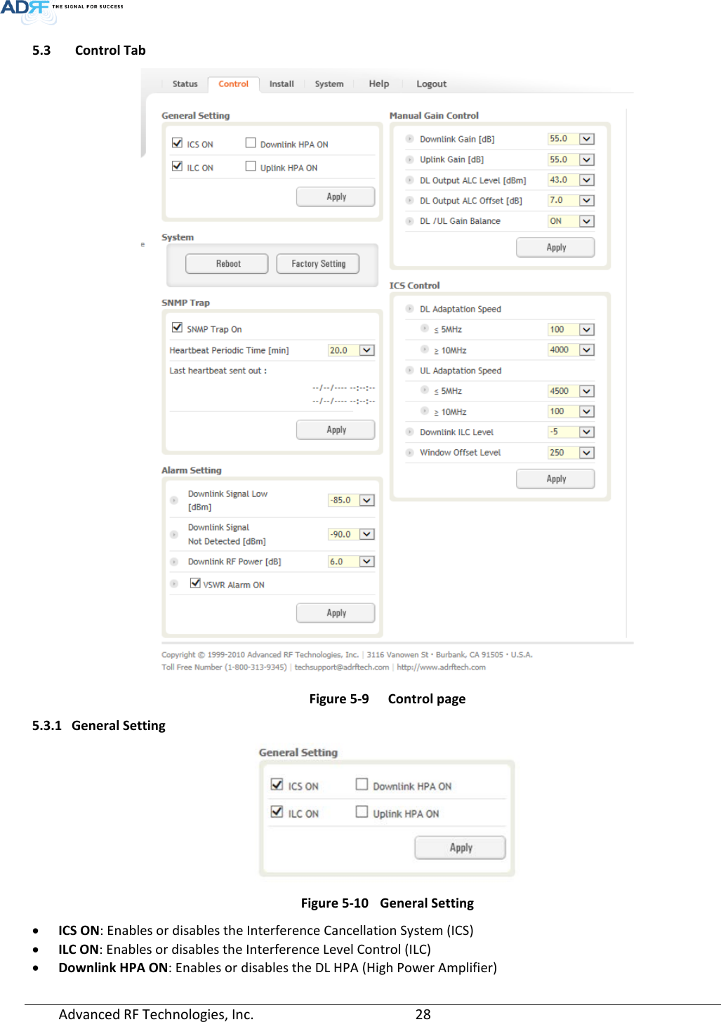
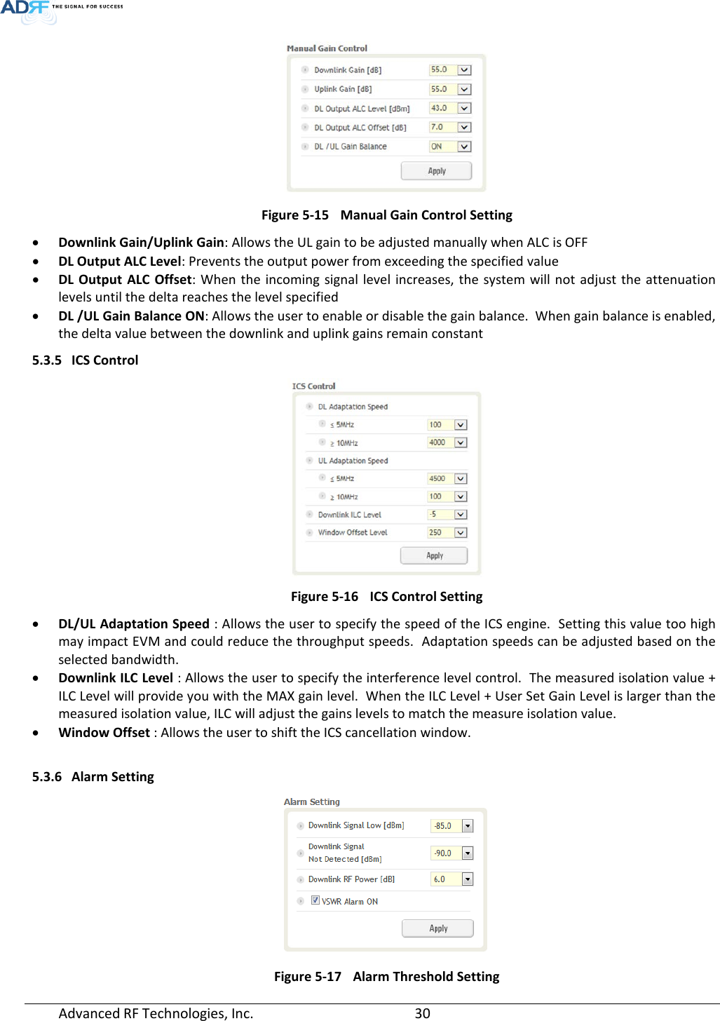
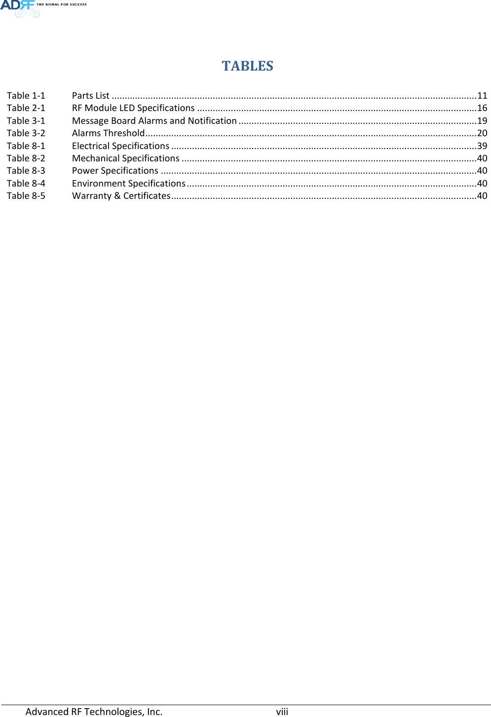
![• Uplink HPA ON: Enables or disabled the UL HPA (High Power Amplifier) To enable any of the settings, click on the checkbox and click the Apply button. WARNING: Inserting a CW signal into the AXM700-9543 when ICS is enabled will cause the system to generate a false alarm. The false alarm will cause the system to go into a shutdown state. If a CW signal needs to be injected into the repeater for testing purposes, the ICS routine must be turned off. 5.3.2 System Figure 5-11 System • Reboot: Clicking the reboot button will have the following popup show up: Figure 5-12 Pop-up message when Reboot button is pressed Click OK to reboot the repeater or click Cancel to exit out • Factory Setting: Resets the repeater to the original factory settings Figure 5-13 Pop-up message when Factory Setting button is pressed 5.3.3 SNMP Trap Figure 5-14 SNMP Trap • SNMP Trap ON – Enables or Disables SNMP traps from being sent out when an alarm is triggered. • Heartbeat Periodic Time [min] – Specifies the amount time between heartbeats 5.3.4 Manual Gain Control Advanced RF Technologies, Inc. 29](https://usermanual.wiki/Advanced-RF-Technologies/AXM1900-9543I/User-Guide-2259931-Page-29.png)