Aironet Wireless Communications 102038 Direct Sequence Spread Spectrum Data Transceiver User Manual
Aironet Wireless Communications Inc Direct Sequence Spread Spectrum Data Transceiver
UserManual.wiki
>
Aironet Wireless Communications
>
102038 User Manual
>
manual
Contents
1.
exerpt from users manual
2.
manual
manual
Navigation menu
Upload a User Manual
Namespaces
Wiki Guide
HTML
PDF
Info
Views
User Manual
Discussion / Help
Navigation
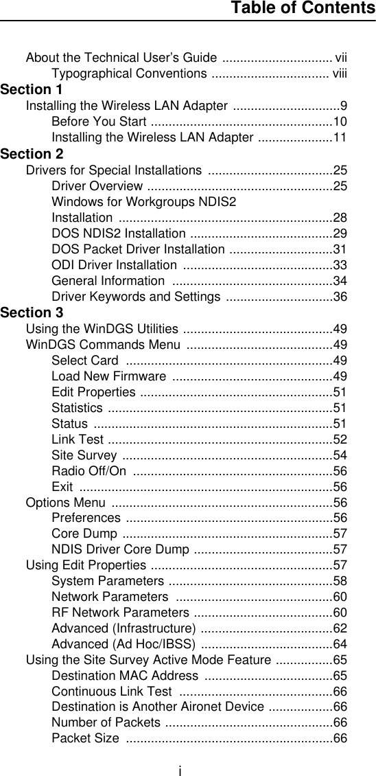

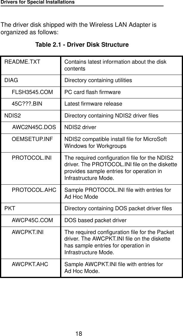
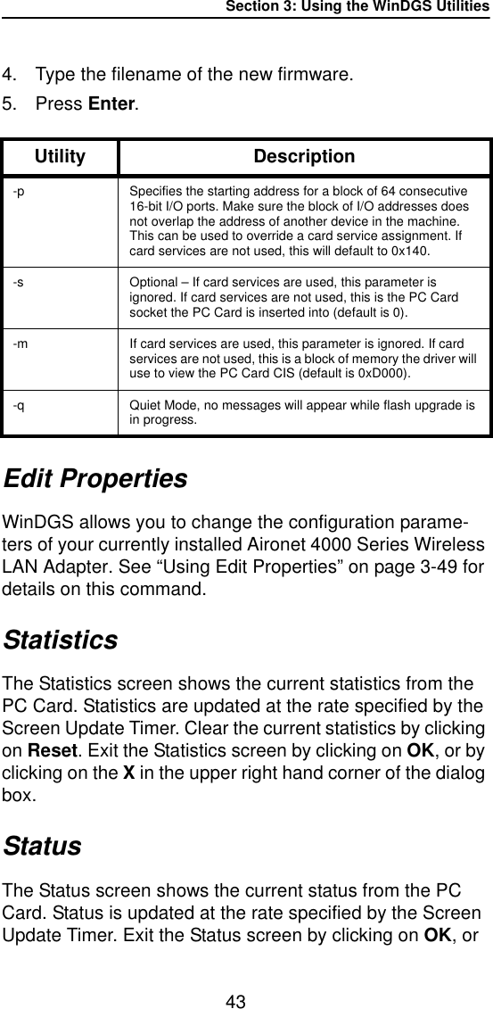
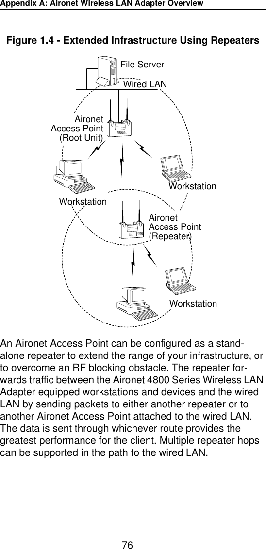
![Drivers for Special Installations21DOS NDIS2 InstallationThe Aironet Wireless LAN Adapter can be installed in a NetBIOS compliant DOS environment such as MicroSoft LAN Manager or PC LAN.The installation of this driver includes creating or editing a configuration file (PROTOCOL.INI). PROTOCOL.INI must contain the following lines:Table 2.2 - Minimum PROTOCOL.INI Driver SettingsAdditional variables defined in the following section may also be used.1. Power on your computer.2. Copy the \NDIS2\AWC2N45C.DOS from the Aironet Device Driver diskette to the directory containing the network files.3. Copy the PROTOCOL.INI file to the network directory or merge statements from the Aironet supplied file into your existing PROTOCOL.INI file.4. Modify the CONFIG.SYS file. After the line containing: Device=PROTMAN.DOS, add Device=[drive:] [path] AWC2N45C.DOS.Infrastructure Mode Ad Hoc Mode[AW2N45C] [AW2N45C]DRIVERNAME=AWC2N45C$ DRIVERNAME=AWC2N45C$If INFRASTRUCTURE is omitted the default will be “ON”INFRASTRUCTURE = “NO”SSID = “your_SSID_here”SSID = “your_SSID_here”CHANNEL = <channel>](https://usermanual.wiki/Aironet-Wireless-Communications/102038.manual/User-Guide-65848-Page-27.png)
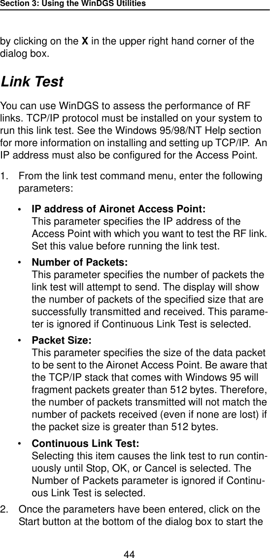
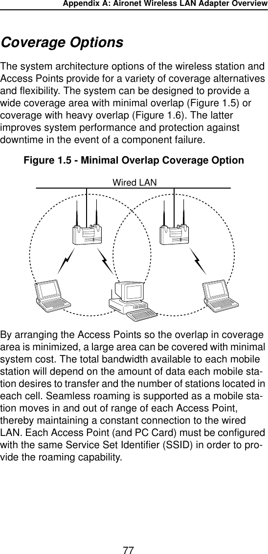
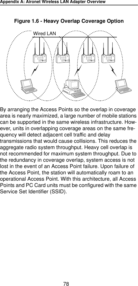
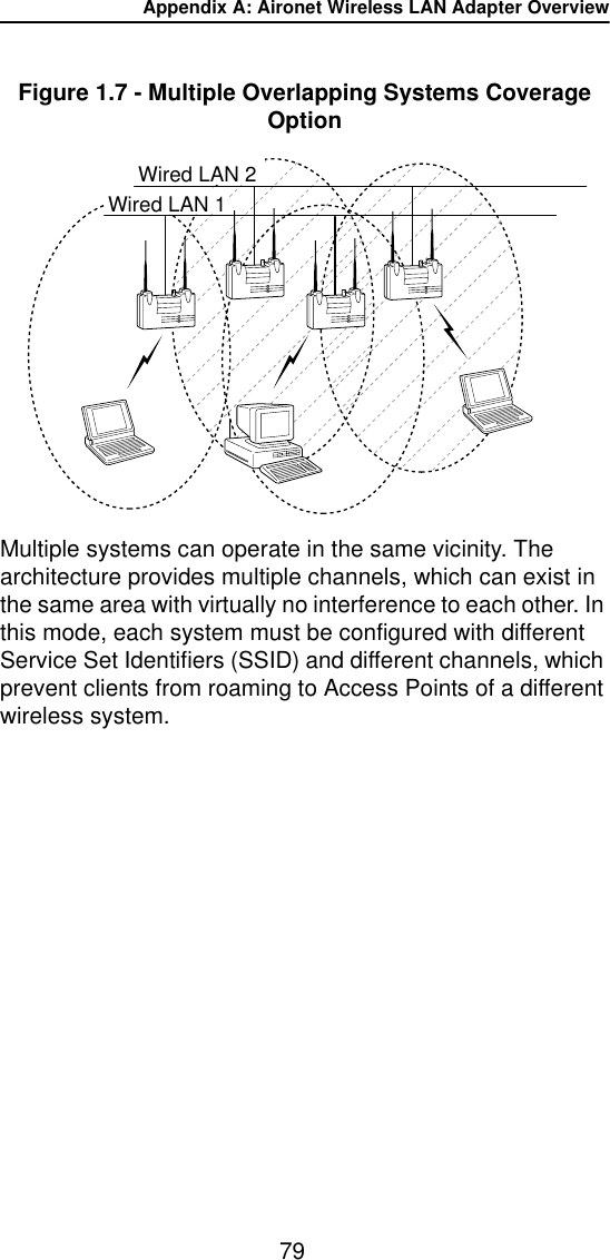
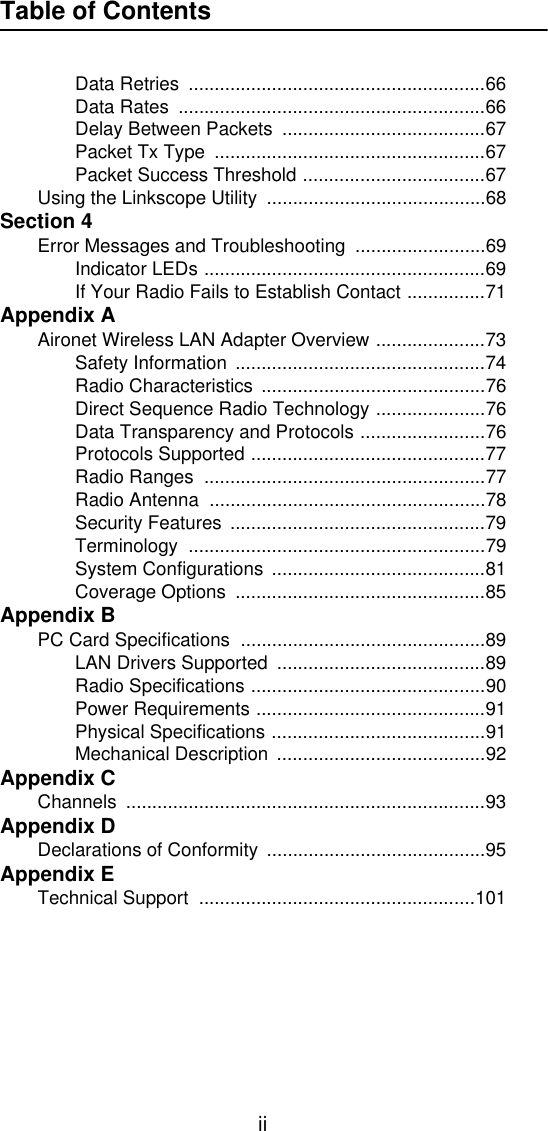
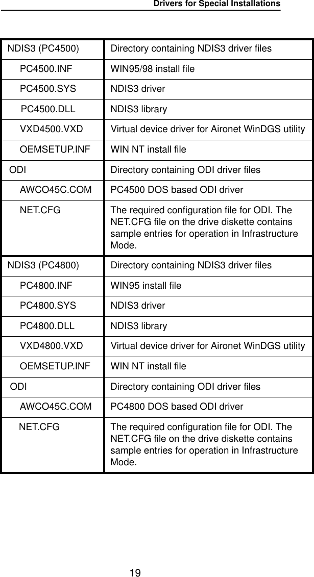
![Drivers for Special Installations23DOS Packet Driver InstallationThe installation of this driver includes creating or editing a configuration file (AWCPKT.INI). This file must contain the following lines:Table 2.3 - Minimum AWCPKT.INI Driver SettingsAdditional variables defined in the following section may also be used.The Wireless LAN Adapter can be installed in a DOS environment using DOS IP stack products such as FTP software.1. Power on your computer.2. Copy the \PKT\AWCP45C.COM file from the Aironet Device Driver diskette to the directory containing the network files.3. Copy the AWCPKT.INI file from the Aironet Device Driver diskette to the directory containing the Packet driver.4. If you would like to modify the PC Card system parame-ters, edit the AWCPKT.INI file. For a list of parameters which can be modified, see Table 3.3.Infrastructure Mode Ad Hoc Mode[AWCPKT] [AWCPKT]If INFRASTRUCTURE is omit-ted the default will be “ON”INFRASTRUCTURE = “NO”SSID = “your_SSID_here”SSID = “your_SSID_here”CHANNEL = <channel>](https://usermanual.wiki/Aironet-Wireless-Communications/102038.manual/User-Guide-65848-Page-29.png)
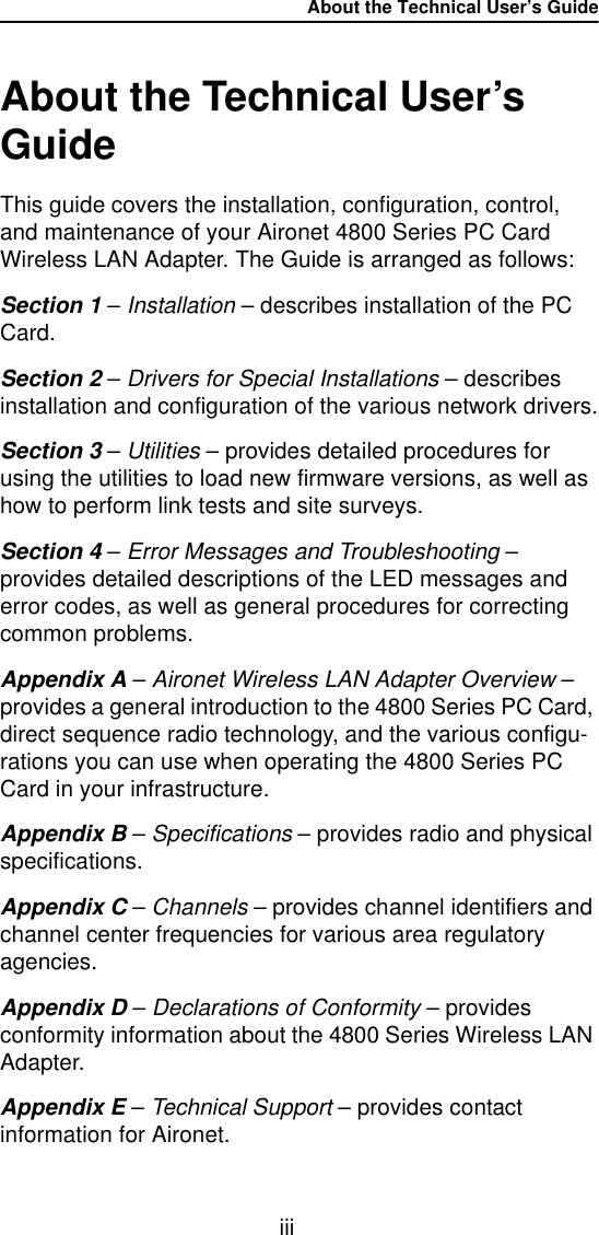
![Drivers for Special Installations245. Load the driver by typing AWCP45C [-cinuw] <int_number> at the DOS prompt (i.e. AWCP45C 0x65) and press Enter.NOTE: To unload the driver, type AWCP45C –u <int_number> (i.e. AWCP45C –u 0x65).6. Load the DOS IP stack.](https://usermanual.wiki/Aironet-Wireless-Communications/102038.manual/User-Guide-65848-Page-30.png)
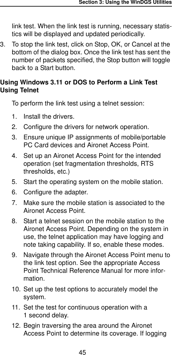
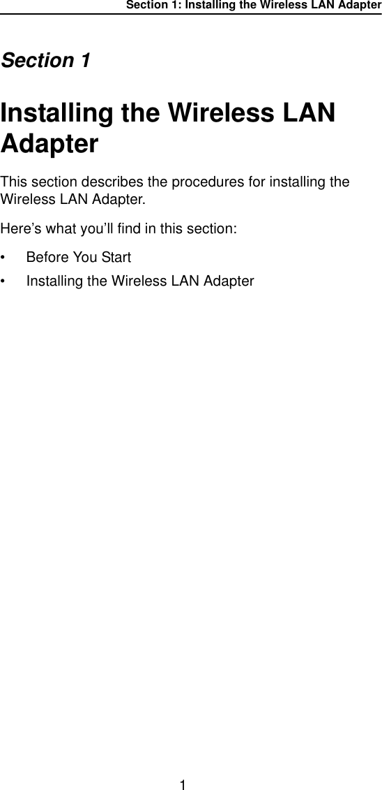
![Drivers for Special Installations26General Information•AWCPKT.INI file must have a section header of [AWCPKT].•PROTOCOL.INI file can have any section header, but the section must contain the keyword and parameter DRIVERNAME=ìAWC2N45C$î.•NET.CFG file must have a section header of [Link Driver AWCO45C].NOTE: These lines may appear anywhere within a section. Only the sections that contain these lines will be parsed.•Multiple sections are supported.•Blank lines are supported.•Comments begin with semi-colon and may appear any-where on a line.•Keywords can be upper or lower case and may be sur-rounded by white space if desired.•Any parameter that begins with “0x” will be assumed to be hexadecimal. Any parameter that begins with a digit (excluding the “0x” case) will be assumed to be deci-mal. Any parameter that begins with quotes will be assumed to be a quoted string parameter. Any other parameter will be assumed to be an unquoted string parameter.•For PROTOCOL.INI string parameters, double quotes are required around the string if the string contains any special characters.NOTE: PROTOCOL.INI does not support some of the white space characters in a quoted string. If a string begins with an alphabetic character and contains no special characters, the quotes may be omitted.](https://usermanual.wiki/Aironet-Wireless-Communications/102038.manual/User-Guide-65848-Page-32.png)
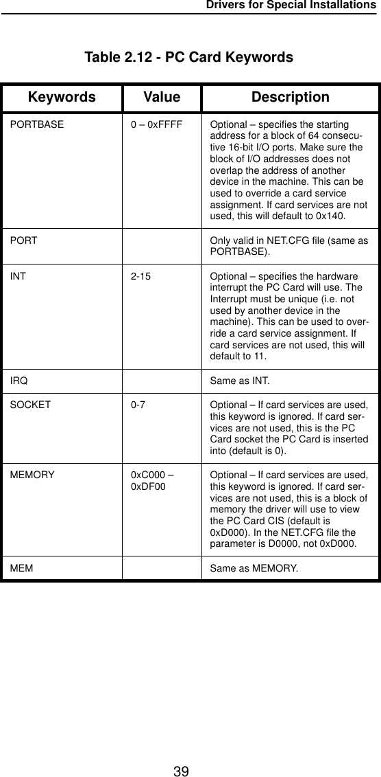
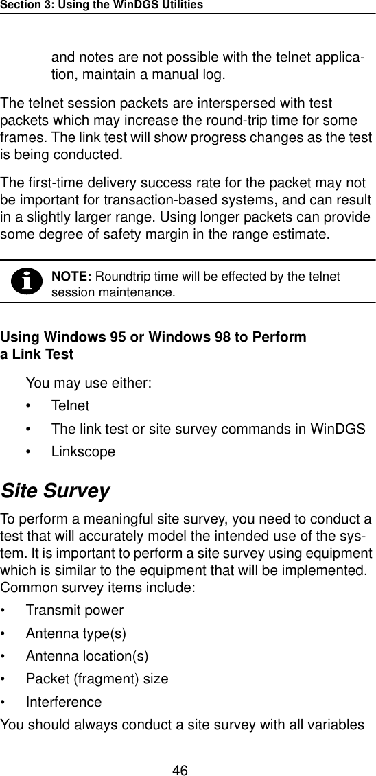
![Drivers for Special Installations29The following tables contain keywords and parameter set-tings common to both the NDIS2 PROTOCOL.INI, ODI NET.CFG, and the PKT AWCPKT.INI configuration files.Basic system operation can be adjusted with the following parameters.Table 2.5 - General Network KeywordsKeywords Value DescriptionINFRASTRUCTURE ON, YESOFF, NO Optional – specifies whether system operation uses an infrastructure or peer-to-peer/ad hoc network (default is ON, YES).SSID 1 to 32 character string This parameter must match the SSID of the system for proper operation.NODENAME 1 to 16 character string Optional – specifies a readable name for the station.NETADDRESS Any IEEE MAC address except broadcast and multicastOptional – this setting allows for locally administered MAC addresses by overriding the unique MAC ID on the PC Card.NODE ADDRESS Same as NETADDRESS (keyword only valid in NET.CFG file).RXMODE NORMAL,UNICAST,NOMULTICASTOptional – this setting determines what frames are delivered to the driver from the PC Card (default is NORMAL). NORMAL indicates unicast, multicast and broadcast frames are received.DATARATE1 0-255 Optional – specified in increasing speed to identify the network configuration to associate to (default is 1_2 [4500] or 1_11 [4800]).DATARATE2 0-255 Optional – specified in increasing speed to identify the network configuration to associate to.](https://usermanual.wiki/Aironet-Wireless-Communications/102038.manual/User-Guide-65848-Page-35.png)
![Drivers for Special Installations30Network performance can be optimized with the following variables.Table 2.6 - Advanced Network KeywordsKeywords Value DescriptionLONGRETRYLIMIT 0 – 255 Optional – specifies the number of times an unfragmented packet will be retried before the packet is dropped and a transmit error is reported to driver (default is 16).SHORTRETRYLIMIT 0 – 255 Optional – specifies the number of times that a fragmented packet will be retried to gain access before a packet is dropped and a transmit error is reported to the driver (default is 16).RTSTHRESHOLD 0 – 2312 Optional – specifies the minimum frame size, in bytes, for which RTS/CTS delivery will be used. Packets longer than this value will be deliv-ered using RTS/CTS handshaking (default is 300).TXMSDULIFETIME 0 – 0xFFFF Optional – specifies the maximum time to attempt packet delivery (default is 5,000 Kµsec [5 seconds]).RXMSDULIFETIME 0 – 0xFFFF Optional – specifies the maximum time for receiving a fragmented packet (default is 10,000 Kµsec [10 seconds]).TXPOWERLEVEL 0 – 100 Optional – selects the next highest programmed power level for trans-mit in mW.RXDIVERSITY DEFAULT, ON,RIGHT, LEFT Optional – specifies the receive diversity method to be used by the PC Card (default is on).TXDIVERSITY DEFAULT, ON,RIGHT, LEFT Optional – specifies the transmit diversity method to be used by the PC Card (default is on).](https://usermanual.wiki/Aironet-Wireless-Communications/102038.manual/User-Guide-65848-Page-36.png)
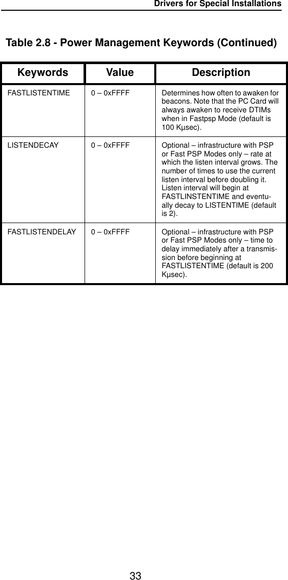
![Drivers for Special Installations32The Wireless LAN Adapter power management can be adjusted with the following group of variables.Table 2.8 - Power Management KeywordsKeywords Value DescriptionPOWERSAVEMODE CAM, PSP, FASTPSP Optional – specifies a particular operational mode (default is CAM).CAM = Constant Awake ModePSP = Power Save ModeFASTPSP = Fast Power Save ModeNote: In Ad Hoc Mode, ATIMDU-RATION must also be set.ATIMDURATION Between 0 and less than the beacon interval.Optional – ad hoc/IBSS only – spec-ifies the length of time in Kµsec for ATIMs following a beacon (this value must be non-zero for PSP ad hoc operation. 0 is Constant Awake Mode (default is 5).This value is only used when start-ing a new network. When joining a network, the value currently in use will be adopted.SLEEPFORDTIM ON, OFF Optional – infrastructure with PSP or Fast PSP Modes only – if ON, the node is allowed to sleep through DTIMs for extra power saving. Broadcast and multicast traffic may be missed (default is OFF).LISTENTIME 0 – 0xFFFF Optional – infrastructure with PSP or Fast PSP Modes only – deter-mines how often to awaken for bea-cons. Note that the PC Card will always awaken to receive DTIMs when in PSP Mode, unless sleep for DTIMs is set (default is 200 Kµsec [200 ms]).](https://usermanual.wiki/Aironet-Wireless-Communications/102038.manual/User-Guide-65848-Page-38.png)
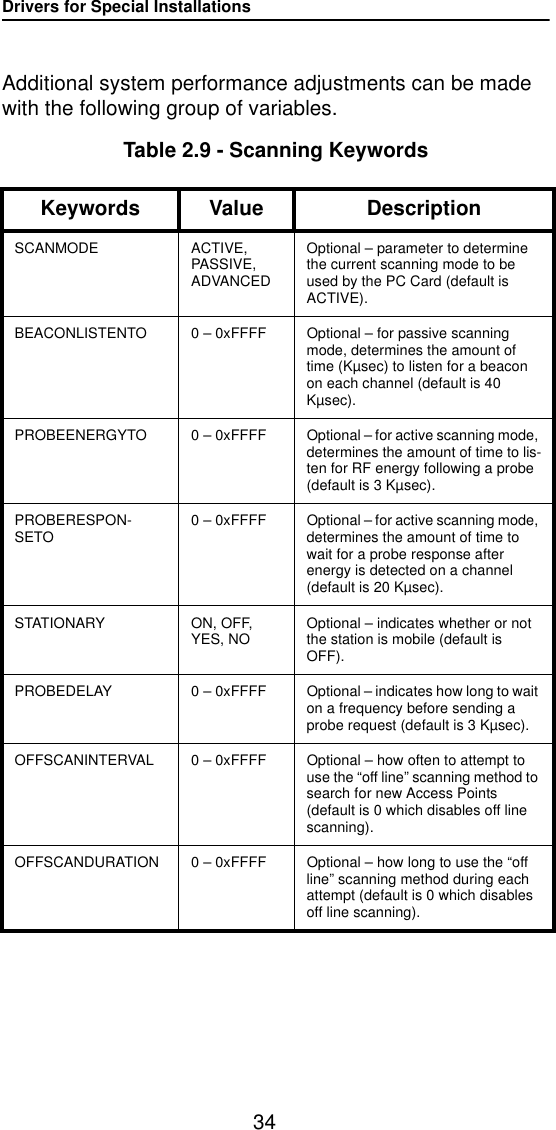
![Drivers for Special Installations35Additional system performance adjustments can be made with the following parameters.Table 2.10 - Infrastructure KeywordsKeywords Value DescriptionSSID 1 to 32 charac-ter string This parameter must match the SSID of the system for proper infra-structure operation.BEACONLOSTTIME 0 – 0xFFFF Optional – determines the interval of consecutively missed beacons which will cause a re-scan (default is 500 Kµsec).REFRESHINTERVAL 0 – 0xFFFF Optional – determines the amount of time in seconds between refresh packets to the Access Point. Use 0xFFFF to disable (default is 10,000 Kµsec [10 sec]).SPECIFIEDAP Any IEEE MAC address except broadcast and multicastOptional – forces association to the specified Access Point.SPECIFIEDAP2 Any IEEE MAC address except broadcast and multicastOptional – forces association to one of the specified Access Points.SPECIFIEDAP3 Any IEEE MAC address except broadcast and multicastOptional – forces association to one of the specified Access Points.SPECIFIEDAP4 Any IEEE MAC address except broadcast and multicastOptional – forces association to one of the specified Access Points.](https://usermanual.wiki/Aironet-Wireless-Communications/102038.manual/User-Guide-65848-Page-41.png)
![Drivers for Special Installations36Table 2.10 - Infrastructure Keywords (Continued)Keywords Value DescriptionSPECIFIEDAPTO 0 – 0xFFFF Optional – time in Kµsec to attempt to associate to a specified Access Point before searching for any avail-able Access Points (with matching SSID) (default is 10,000 Kµsec [10 sec]).AUTHTIMEOUT 0 – 0xFFFF Optional – time to attempt to authen-ticate to an Access Point (default is 2,000 Kµsec [2 sec]).AUTHTYPE OFF, OPEN,HAREDKEY,ENCRYPTONLYOptional – determines the level of security of the wireless network (default is OPEN).ASSOCIATIONTO 0 – 0xFFFF Optional – indicates the maximum amount of time the client will wait for a response to an association request from the Access Point (default is 2,000 Kµsec [2 sec]).](https://usermanual.wiki/Aironet-Wireless-Communications/102038.manual/User-Guide-65848-Page-42.png)
![Drivers for Special Installations37Ad hoc system operation is accomplished with the following group of variables.Table 2.11 - Ad Hoc KeywordsKeywords Value DescriptionJOINNETTO 0 – 0xFFFF Optional – determines the amount of time that an ad hoc station will scan before starting its own network (default is 10,000 Kµsec [10 sec]).BEACONPERIOD 0 – 0xFFFF Optional – specifies the beaconing interval in Kµsec. (default is 100 Kµsec).DSCHANNEL 0-14 Optional – this parameter is valid only for a node that starts a network. This is the channel identifier specify-ing the frequency to communicate on. For all other nodes, the radio will scan for the proper frequency. Default is 0, which will cause the radio to pick a default channel appropriate for its programmed carrier set. Any other value (1-14) will be validated against the programmed carrier set and rejected if invalid.ATIMDURATION Between 0 and less than the beacon intervalAd hoc only – specifies the length of time for ATIMs following a beacon (this value must be non-zero for PSP ad hoc operation) (default is 5).This value is only used when start-ing a new network. When joining a network, the value currently in use will be adopted.](https://usermanual.wiki/Aironet-Wireless-Communications/102038.manual/User-Guide-65848-Page-43.png)