Airspan Networks H4K425 Base station of LTE fixed cellular system User Manual AirHarmony 4400 ext Installation Guide
Airspan Networks Inc Base station of LTE fixed cellular system AirHarmony 4400 ext Installation Guide
UserManual.wiki
>
Airspan Networks
>
H4K425 User Manual
Users Manual
Navigation menu
Upload a User Manual
Namespaces
Wiki Guide
HTML
PDF
Info
Views
User Manual
Discussion / Help
Navigation
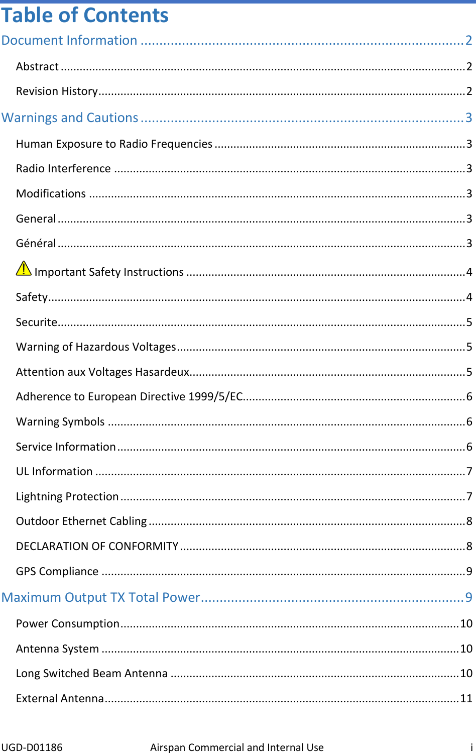

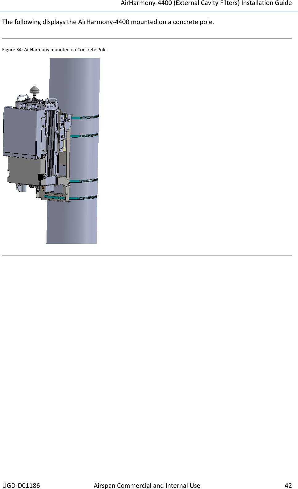
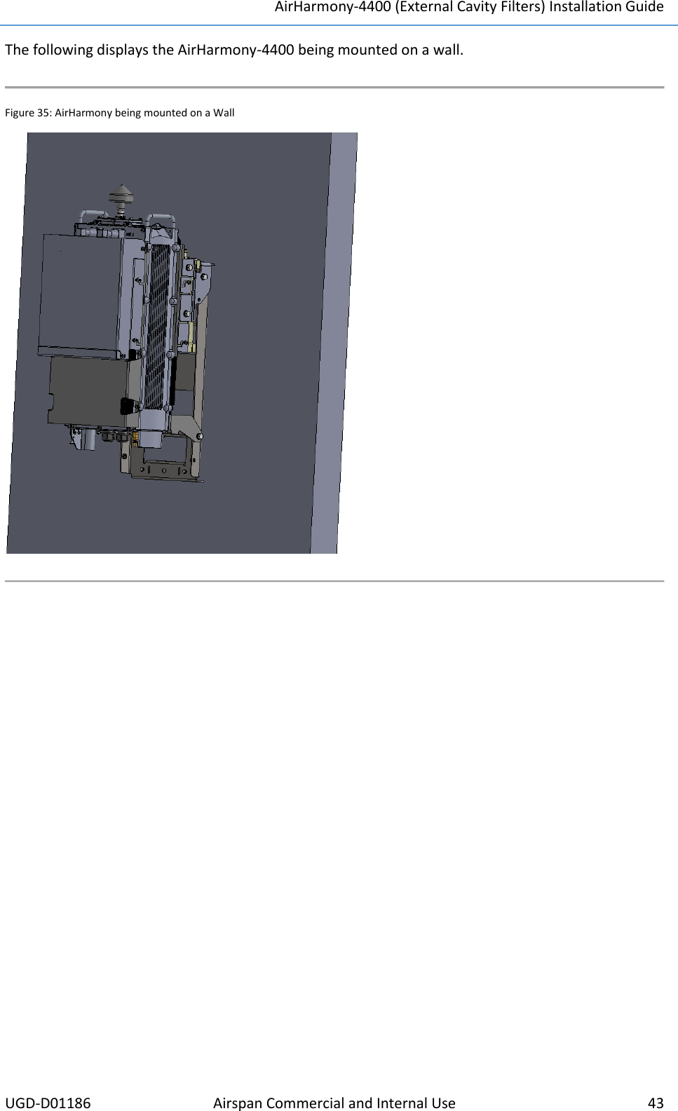
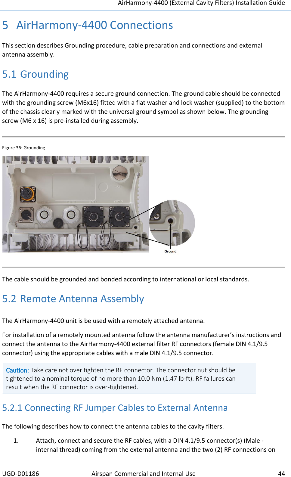
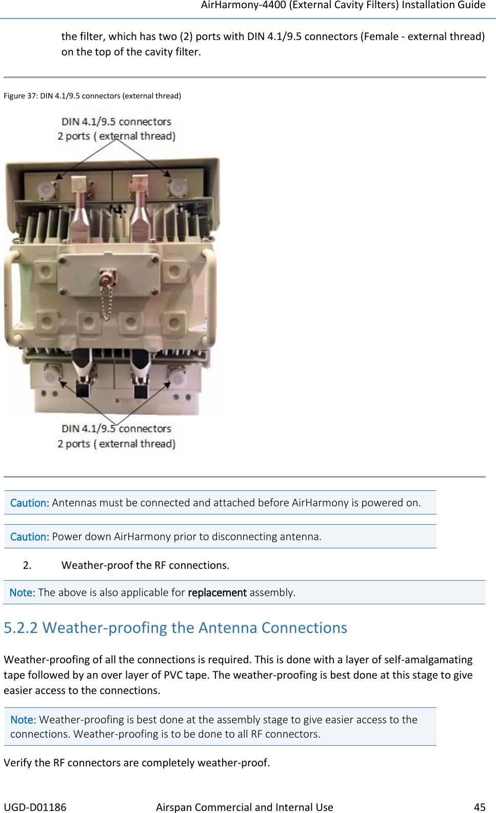
![AirHarmony-4400 (External Cavity Filters) Installation Guide UGD-D01186 Airspan Commercial and Internal Use 27 Figure 9: Back Bracket Assembly 12. Slide the filter to align it with its RF connector and fit together, then tighten the connector. Figure 10: Fitting RF Connector Caution: Take care not to over tighten the RF connector. The connector nut should be tightened to a nominal torque of no more than 15 [N*m] (11.06 lb-ft). Using either 22 mm or 7/8” open end torque wrench. 13. After tightening both RF connectors, proceed to tighten the eight (8) M5 screws on the filters Figure 11. Tighten the Filter Screws](https://usermanual.wiki/Airspan-Networks/H4K425/User-Guide-3251620-Page-33.png)
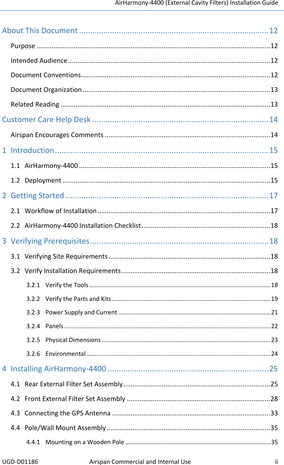
![AirHarmony-4400 (External Cavity Filters) Installation Guide UGD-D01186 Airspan Commercial and Internal Use 31 8. Pull outward on the filter cover to pull it free and swing the filter cover down away from the cavity filters and open the cover completely. Figure 18. Cover opened 9. Slide the filter to align it with its RF connector and fit together, then tighten the connector. Caution: Take care not to over tighten the RF connector. The connector nut should be tightened to a nominal torque of no more than 15 [N*m] (11.06 lb-ft). Using either 22mm or 7/8” open end torque wrench. Figure 19: Align and fit filter to connector 10. Next tighten the four (4) screws which fasten the filter to the filter bridge.](https://usermanual.wiki/Airspan-Networks/H4K425/User-Guide-3251620-Page-37.png)
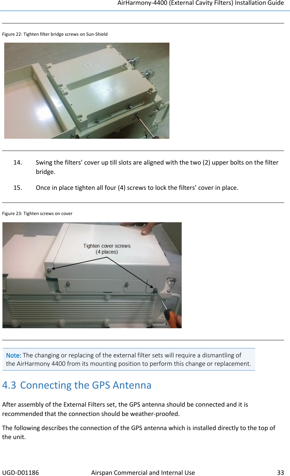
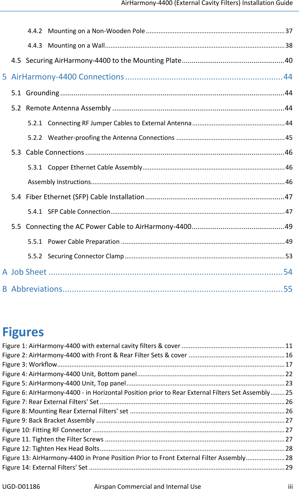
![AirHarmony-4400 (External Cavity Filters) Installation Guide UGD-D01186 Airspan Commercial and Internal Use 32 Figure 20: Tighten screws on filter 11. Slide the second filter to align it with its RF connector and fit together, then tighten the connector. Caution: Take care not to over tighten the RF connector. The connector nut should be tightened to a nominal torque of no more than 15 [N*m] (11.06 lb-ft). Using either 22mm or 7/8” open end torque wrench. Figure 21: Align and fit second filter to connector 12. Tighten the four (4) screws which fasten the second filter to the filter bridge. 13. Tighten the four (4) screws which fasten the filter bridge to the Sun-Shield. Airspan recommends weather-proofing the RF connections. Note: Weather-proofing of all the connections is recommended. This is done with a layer of self-amalgamating tape followed by an over layer of PVC tape. The weather-proofing is best done at this stage to give easier access to the connections.](https://usermanual.wiki/Airspan-Networks/H4K425/User-Guide-3251620-Page-38.png)