Alcatel USA 8505U-2 Digitally Modulated Radio User Manual 01 General
Alcatel USA Marketing, Inc. Digitally Modulated Radio 01 General
UserManual.wiki
>
Alcatel USA
>
8505U-2 User Manual
>
General
Contents
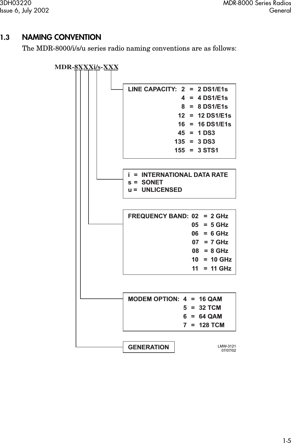
1.
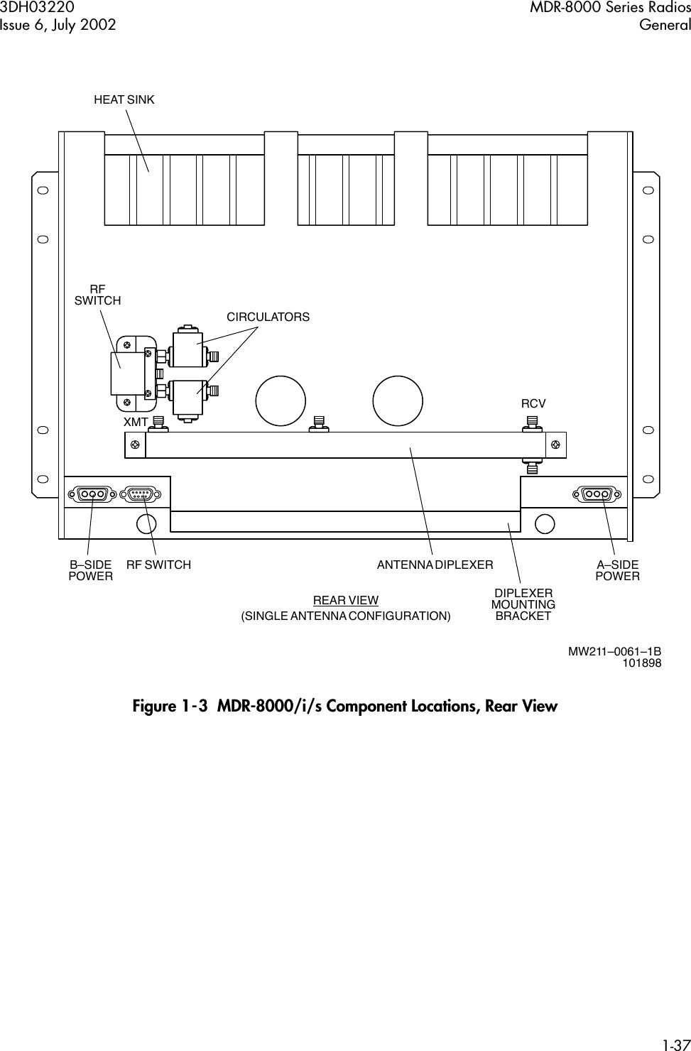
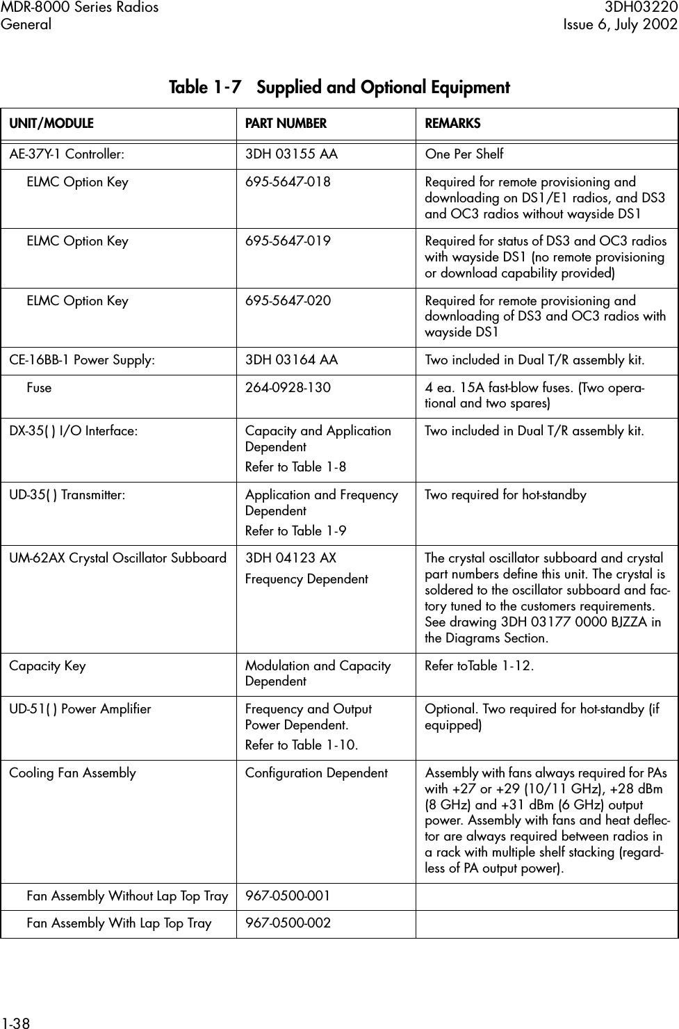
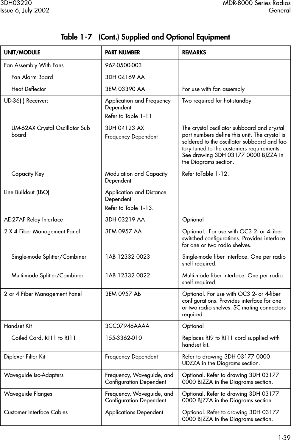
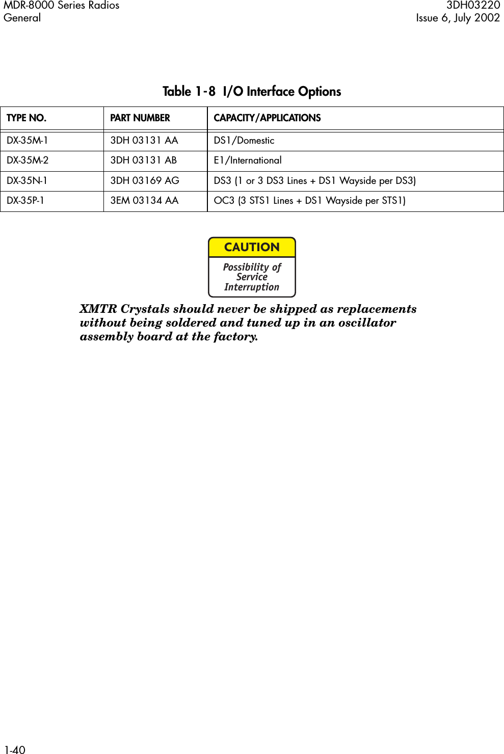
General
2.
Initial Turnup
General
Navigation menu
Upload a User Manual
Namespaces
Wiki Guide
HTML
PDF
Info
Views
User Manual
Discussion / Help
Navigation