Andrew Wireless Innovations Group RPT-MR701 REPEATER User Manual M0050A0B

Andrew Wireless Innovations Group REPEATER M0050A0B

Contents

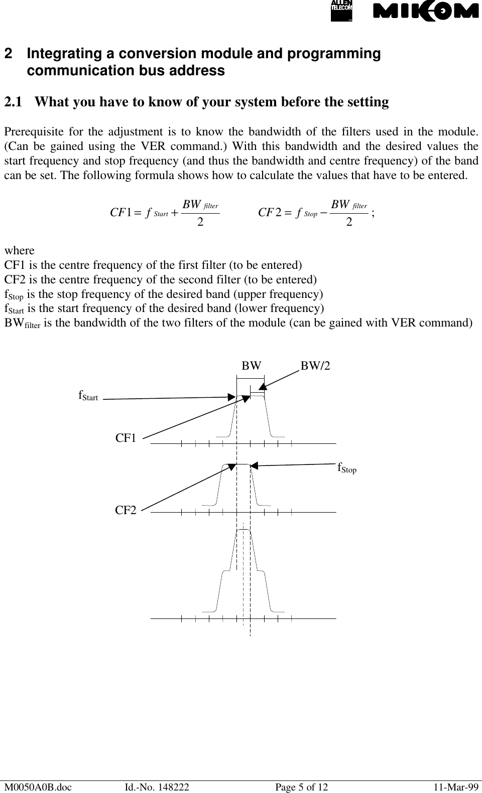
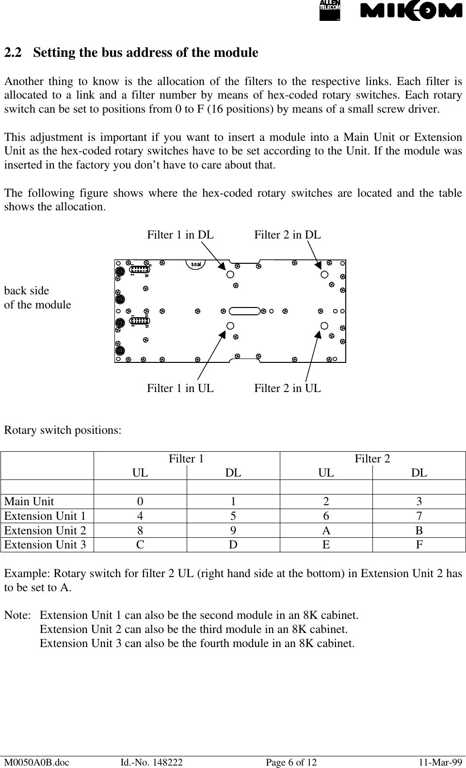
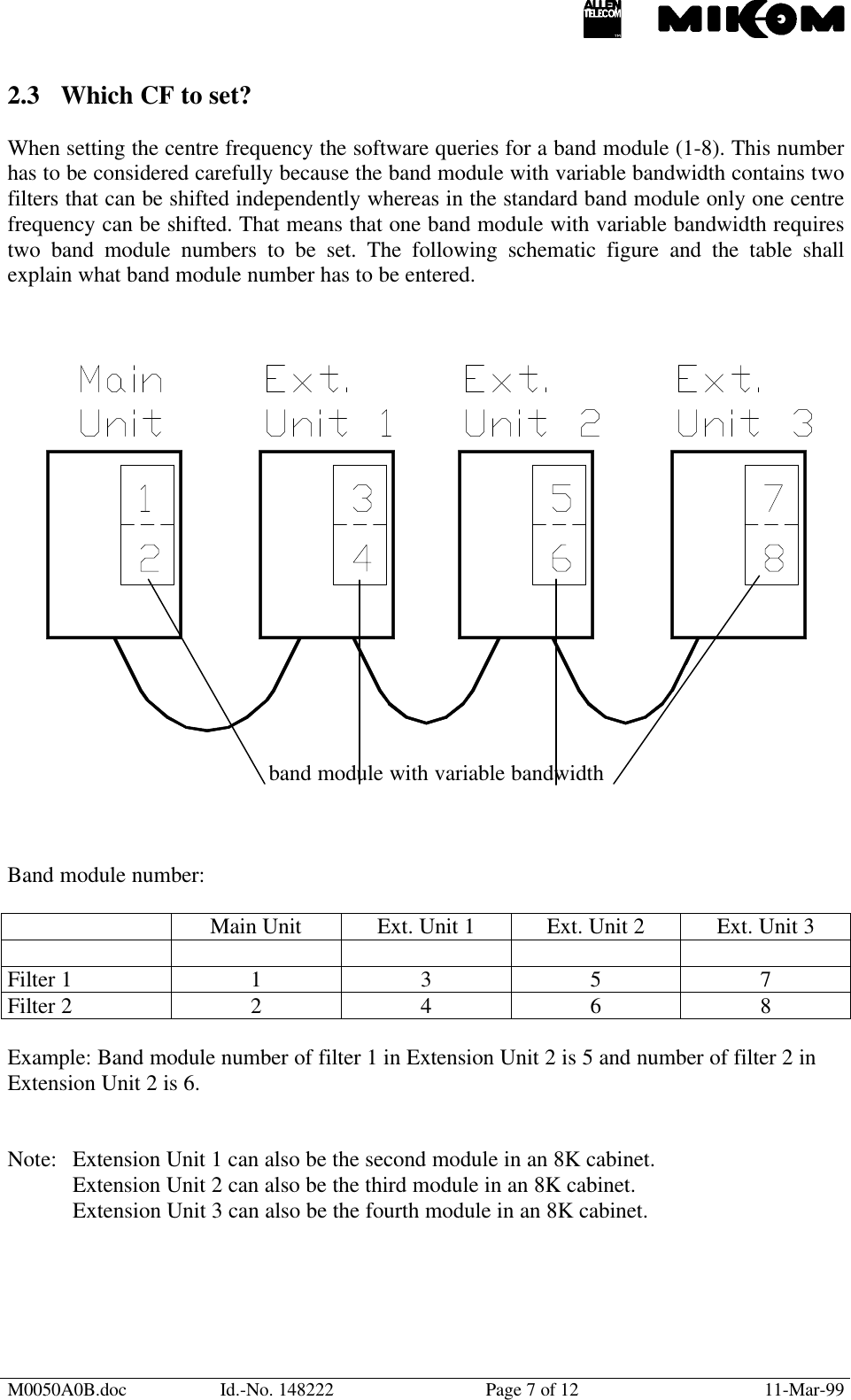
Functional description and integration instructions manual

M0050A0B.doc Id.-No. 148222 Page 1 of 12 11-Mar-99Functional descriptionandintegration instructionsfor Repeater usingband modules withvariable bandwidth.
M0050A0B.doc Id.-No. 148222 Page 2 of 12 11-Mar-99Contents1Functional description........................................................................................32Integrating a conversion module and programming communication busaddress......................................................................................................................52.1 What you have to know of your system before the setting.....................................52.2 Setting the bus address of the module.....................................................................62.3 Which CF to set? .....................................................................................................72.4 Attenuation setting..................................................................................................82.5 Required software commands.................................................................................93Example .............................................................................................................104Quick reference for experienced users........................................................... 124.1 Frequency adjustment in UL and DL in module 1...............................................124.2 Frequency adjustment in UL and DL in modules 2/3/4.......................................124.3 Attenuation............................................................................................................12
M0050A0B.doc Id.-No. 148222 Page 3 of 12 11-Mar-991 Functional descriptionThe band module with variable bandwidth can be set to a desired centre frequency and to adesired bandwidth.The explanation how it works is made with reference to the following figures and exemplaryvalues for frequencies, bandwidths and levels.There are two filters in one link (UL or DL) in series in the band module which can be set to adefined centre frequency. In the example we have two filters with a bandwidth of 25 MHzeach and for demonstration purposes the frequency range is 870 to 940 MHz.In Fig. 1 we see that filter 1 and filter 2 are both set to a centre frequency (CF) of 900 MHz.The resulting overall response of the module is thus a 25 MHz band with a centre frequencyof 900 MHz (⇒ frequency range from 887.5 MHz to 912.5 MHz). The attenuation in the stopband of one filter was assumed to be 40 dB. Thus, the overall attenuation of the module is80 dB.Fig. 1 Fig. 2
M0050A0B.doc Id.-No. 148222 Page 4 of 12 11-Mar-99In Fig. 2 we have the same filters but this time with different centre frequencies. The centrefrequency of filter 1 is this time 912.5 MHz and the centre frequency of filter 2 is again900 MHz. Consequently, we get another overall response of the module as can be seen infig. 2. Filter 1 limits the frequency range towards lower frequencies and filter 2 towardshigher frequencies. The resulting response is thus an attenuation of 80 dB up to 881.25 MHz,40 dB up to 893.25 MHz, 3 dB bandwidth is 12.5 MHz from 900 MHz to 912 MHz, 40 dBattenuation from 918.75 MHz and 80 dB from 931.25 MHz. (Values exemplary!)It is shown in the following how the centre frequency and the bandwidth of the module can beset to desired values.
M0050A0B.doc Id.-No. 148222 Page 5 of 12 11-Mar-992 Integrating a conversion module and programmingcommunication bus address2.1 What you have to know of your system before the settingPrerequisite for the adjustment is to know the bandwidth of the filters used in the module.(Can be gained using the VER command.) With this bandwidth and the desired values thestart frequency and stop frequency (and thus the bandwidth and centre frequency) of the bandcan be set. The following formula shows how to calculate the values that have to be entered.21filterStart BWfCF +=22filterStop BWfCF −= ;whereCF1 is the centre frequency of the first filter (to be entered)CF2 is the centre frequency of the second filter (to be entered)fStop is the stop frequency of the desired band (upper frequency)fStart is the start frequency of the desired band (lower frequency)BWfilter is the bandwidth of the two filters of the module (can be gained with VER command)BW BW/2fStartCF1fStopCF2
M0050A0B.doc Id.-No. 148222 Page 6 of 12 11-Mar-992.2 Setting the bus address of the moduleAnother thing to know is the allocation of the filters to the respective links. Each filter isallocated to a link and a filter number by means of hex-coded rotary switches. Each rotaryswitch can be set to positions from 0 to F (16 positions) by means of a small screw driver.This adjustment is important if you want to insert a module into a Main Unit or ExtensionUnit as the hex-coded rotary switches have to be set according to the Unit. If the module wasinserted in the factory you don’t have to care about that.The following figure shows where the hex-coded rotary switches are located and the tableshows the allocation.Filter 1 in DL Filter 2 in DLback sideof the moduleFilter 1 in UL Filter 2 in ULRotary switch positions:Filter 1 Filter 2UL DL UL DLMain Unit 0 1 2 3Extension Unit 1 4 5 6 7Extension Unit 2 8 9 ABExtension Unit 3 CDEFExample: Rotary switch for filter 2 UL (right hand side at the bottom) in Extension Unit 2 hasto be set to A.Note: Extension Unit 1 can also be the second module in an 8K cabinet.Extension Unit 2 can also be the third module in an 8K cabinet.Extension Unit 3 can also be the fourth module in an 8K cabinet.
M0050A0B.doc Id.-No. 148222 Page 7 of 12 11-Mar-992.3 Which CF to set?When setting the centre frequency the software queries for a band module (1-8). This numberhas to be considered carefully because the band module with variable bandwidth contains twofilters that can be shifted independently whereas in the standard band module only one centrefrequency can be shifted. That means that one band module with variable bandwidth requirestwo band module numbers to be set. The following schematic figure and the table shallexplain what band module number has to be entered.band module with variable bandwidthBand module number:Main Unit Ext. Unit 1 Ext. Unit 2 Ext. Unit 3Filter 1 1 3 5 7Filter 2 2 4 6 8Example: Band module number of filter 1 in Extension Unit 2 is 5 and number of filter 2 inExtension Unit 2 is 6.Note: Extension Unit 1 can also be the second module in an 8K cabinet.Extension Unit 2 can also be the third module in an 8K cabinet.Extension Unit 3 can also be the fourth module in an 8K cabinet.
M0050A0B.doc Id.-No. 148222 Page 8 of 12 11-Mar-992.4 Attenuation settingOne band module with variable bandwidth needs to be addressed as if there were two modules(see also chapter 2.2).This means for the attenuation setting that, theoretically, there are two different attenuationsthat can be set in one module. This is, however, wrong. Only one attenuation setting can bedone. This setting has always to be done in the even module number (Filter 2). Thus,attenuation settings can only be done in module numbers 2, 4, 6 and 8.If settings on the odd module numbers are executed the software will show dummy values butthese values are not valid. This attenuation is not really set.Example: If you want to set the attenuation of the band module with variable bandwidth in theExtension Unit 2 you have to set the attenuation via software in the band module 6. See alsotable in chapter 2.3.Note: Extension Unit 1 can also be the second module in an 8K cabinet.Extension Unit 2 can also be the third module in an 8K cabinet.Extension Unit 3 can also be the fourth module in an 8K cabinet.
M0050A0B.doc Id.-No. 148222 Page 9 of 12 11-Mar-992.5 Required software commandsThe software command to set the centre frequency (CF1 and CF2) of the filters and theattenuation is given in the following.With the SET CF command the centre frequency of a filter can be set with an accuracy of 10kHz in GSM900 and 100kHz in GSM1800. The SET CFO (centre frequency offset) commandis for correction purposes only and should be avoided if possible. SET CFO can be set in stepsof 10 kHz from – 1000 kHz to + 1000 kHz. (See also software manual for more details.)SET CFSyntax: SET CF ↵ENTER BAND MODULE (1-8): ↵ENTER CF UL <MHz>: ↵ENTER CF DL <MHz>: ↵SET CFOSyntax: SET CFO ↵ENTER BAND MODULE (1-8): ↵ENTER CFO UL <kHz>: ↵ENTER CFO DL <kHz>: ↵SET ATTSyntax: (ENTER Repeater Number (1-4): ↵)  *ENTER BAND MODULE ( 1-8 ): ↵ENTER MODE ( UL or DL): ↵ENTER ATTENUATION: ↵* (This is only valid in some earlier software versions!)Band module number can be found in table “Band module number”.
M0050A0B.doc Id.-No. 148222 Page 10 of 12 11-Mar-993 ExampleAn example shall demonstrate the above statements.For further details how to perform certain actions please refer also to the Repeater manual.Assumed we want to replace a module with variable bandwidth in an Extension Unit 2. Thedesired bandwidth is 16.2 MHz and the desired centre frequency in the UL is 902.5 MHz andin the DL 947.5 MHz. The attenuation in UL has to be set to 16 dB and 22 dB in the DL.First thing is to check whether the rotary switches of the module are in the correct position.The rotary switch for filter 1 in UL has to be in position 8, for filter 1 in DL in position 9, forfilter 2 in UL in position A and for filter 2 in DL in position B. (See table “Rotary switchposition”.)The module has to be inserted and if the bandwidth of the filters in the module is not known itcan be gained with the VER command. Entering the VER command will be responded by(amongst others) the hardware of the Repeater including the bandwidth of the filters. Theresponse for example of the software in a MR301A with 25 MHz filters would be:MR301A-25, where 25 shows the bandwidth in MHz.Next thing to do is to calculate the centre frequencies that have to be entered. With the abovegiven formula we get:UL:21filterStart BWfCF += =  (902.5 – 8.1) MHz + 12.5 MHz = 906.9 MHz22filterStop BWfCF −= =  (902.5 + 8.1) MHz – 12.5 MHz = 898.1 MHzDL:CF1 = (947.5 – 8.1) MHz + 12.5 MHz = 951.9 MHzCF2 = (947.5 + 8.1) MHz – 12.5 MHz = 943.1 MHz
M0050A0B.doc Id.-No. 148222 Page 11 of 12 11-Mar-99Having all the values the centre frequencies can be set with the SET CF commands asfollows: (Band module number can be found in table “Band module number”.)SET CF ↵ENTER BAND MODULE (1-8): 5↵ENTER CF UL <MHz>: 906.9↵ENTER CF DL <MHz>: 951.9↵SET CF ↵ENTER BAND MODULE (1-8): 6↵ENTER CF UL <MHz>: 898.1↵ENTER CF DL <MHz>: 943.1↵And the attenuation can be set as follows:SET ATTENTER BAND MODULE ( 1-8 ): 6↵ENTER MODE ( UL or DL): UL↵ENTER ATTENUATION: 16↵SET ATTENTER BAND MODULE ( 1-8 ): 6↵ENTER MODE ( UL or DL): DL↵ENTER ATTENUATION: 22↵
M0050A0B.doc Id.-No. 148222 Page 12 of 12 11-Mar-994 Quick reference for experienced users4.1 Frequency adjustment in UL and DL in module 1Setting lower band edge:SET CF1Lower band edge + (2bandwidthfilter  )Setting lower band edge:SET CF2Upper band edge - (2bandwidthfilter  )4.2 Frequency adjustment in UL and DL in modules 2/3/4Same as above with 3 and 4 / 5 and 6 / 7 and 8.4.3 AttenuationSET ATT2/4/6/8 (for module 1/2/3/4)Attenuation value

Navigation menu