Andrew Wireless Innovations Group RPT-MR701 REPEATER User Manual M0062A0B
Andrew Wireless Innovations Group REPEATER M0062A0B
UserManual.wiki
>
Andrew Wireless Innovations Group
>
RPT-MR701 User Manual
>
Software manual
Contents
1.
REPEATER MANUAL
2.
Software manual
3.
Functional description and integration instructions manual
4.
Repeater manual
Software manual
Navigation menu
Upload a User Manual
Namespaces
Wiki Guide
HTML
PDF
Info
Views
User Manual
Discussion / Help
Navigation

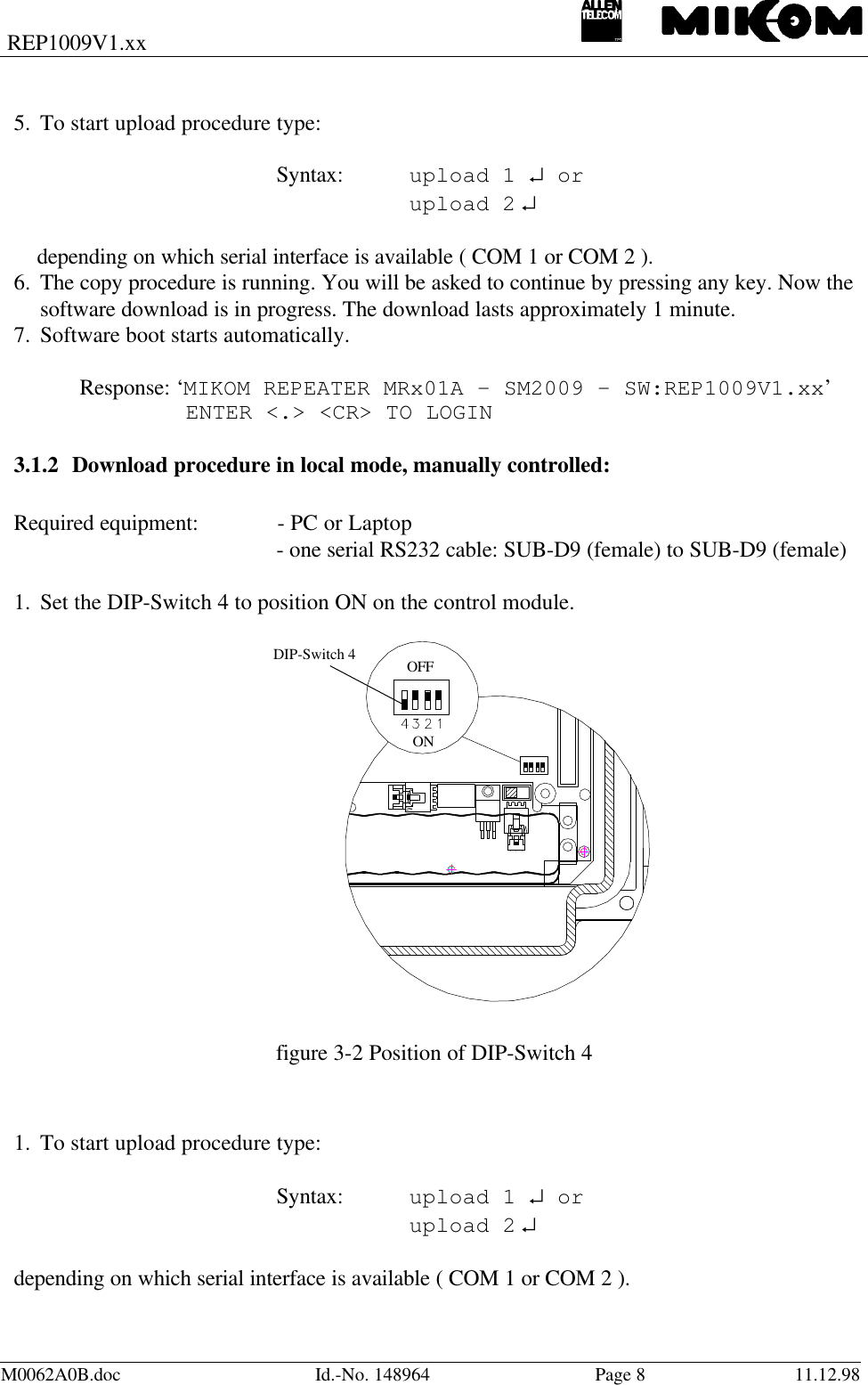

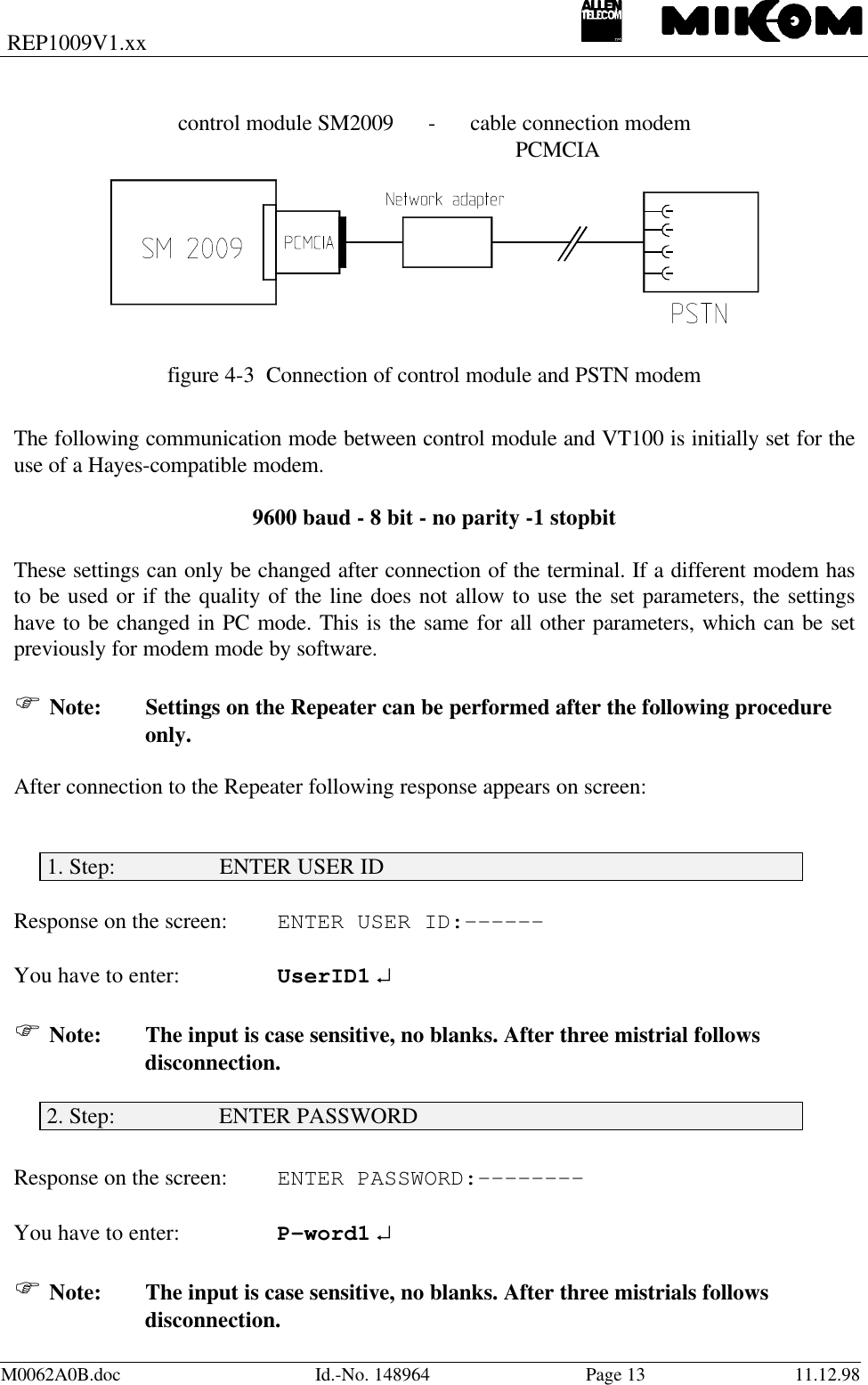
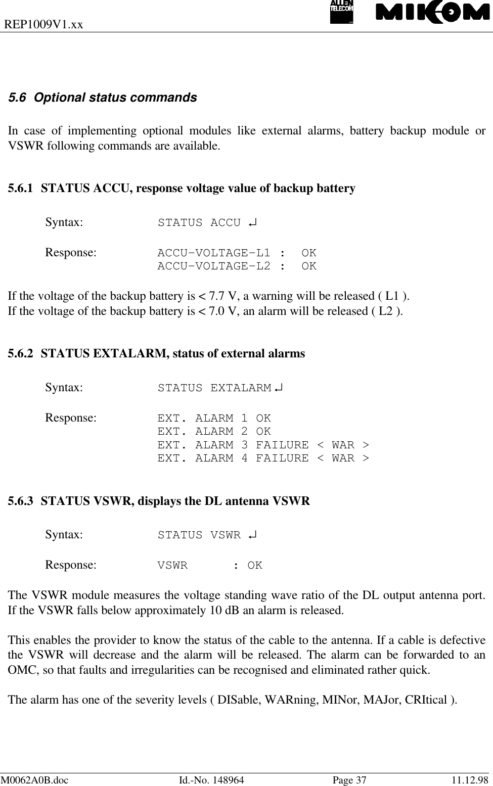
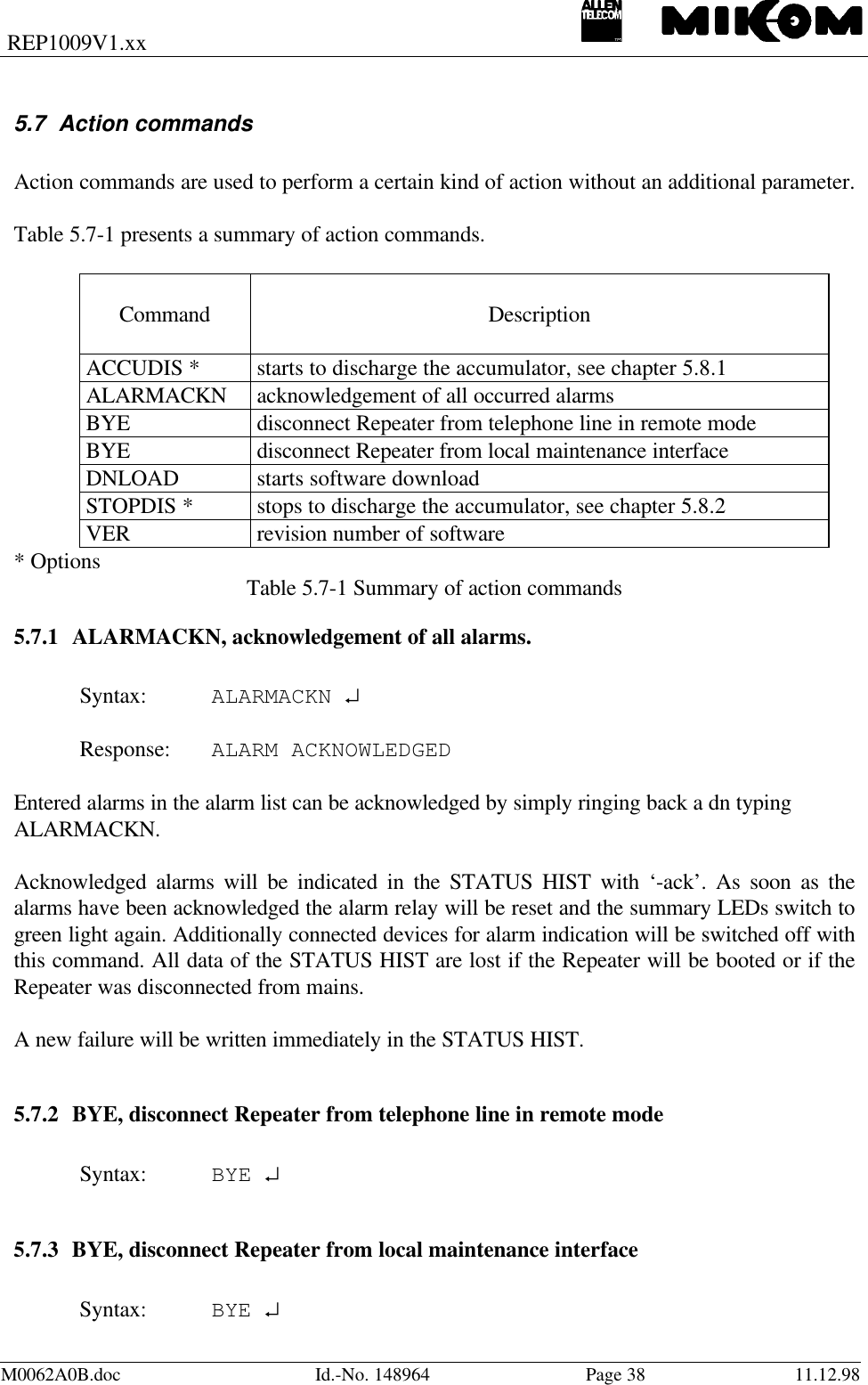
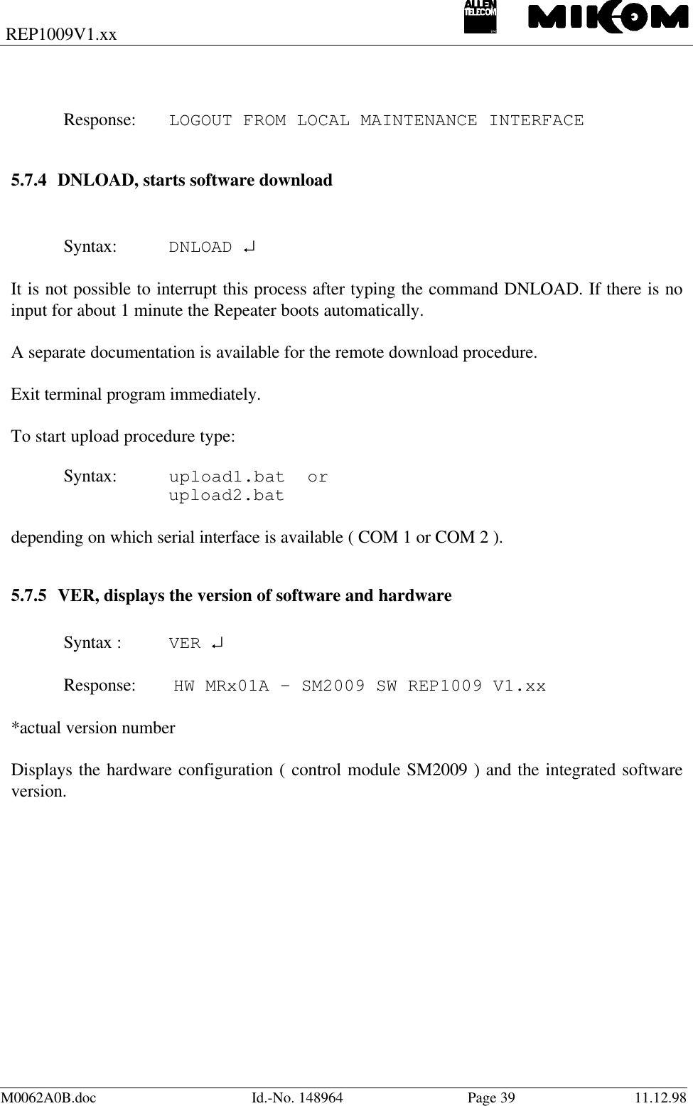
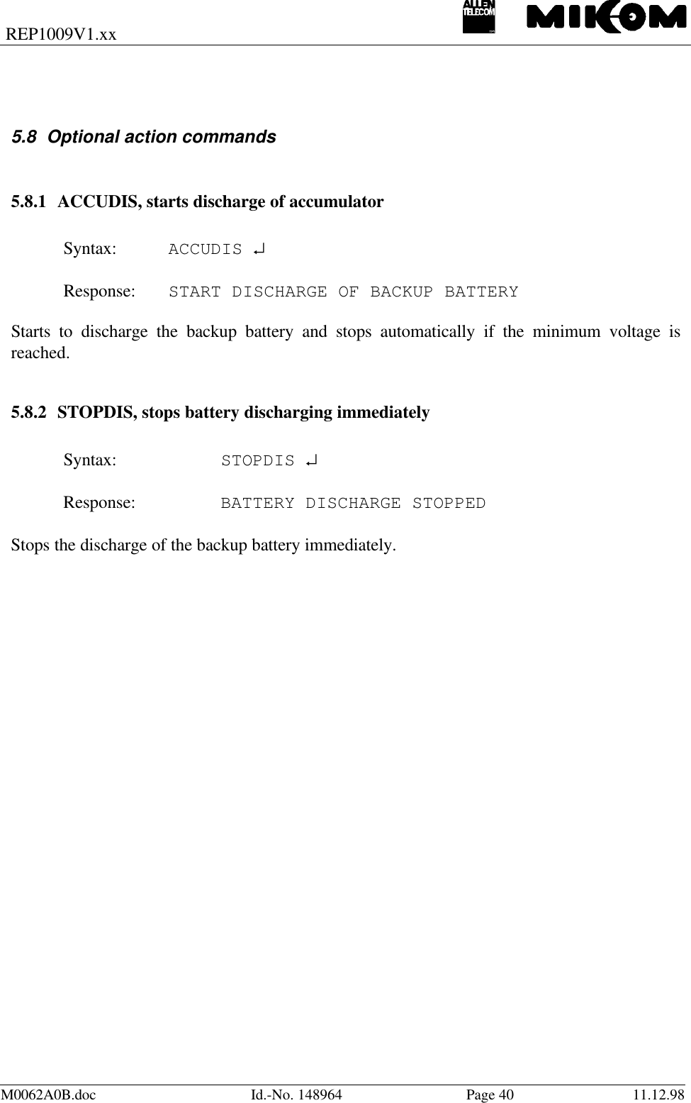
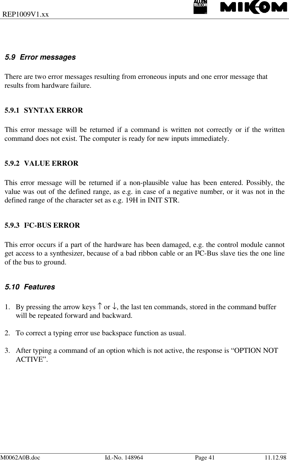
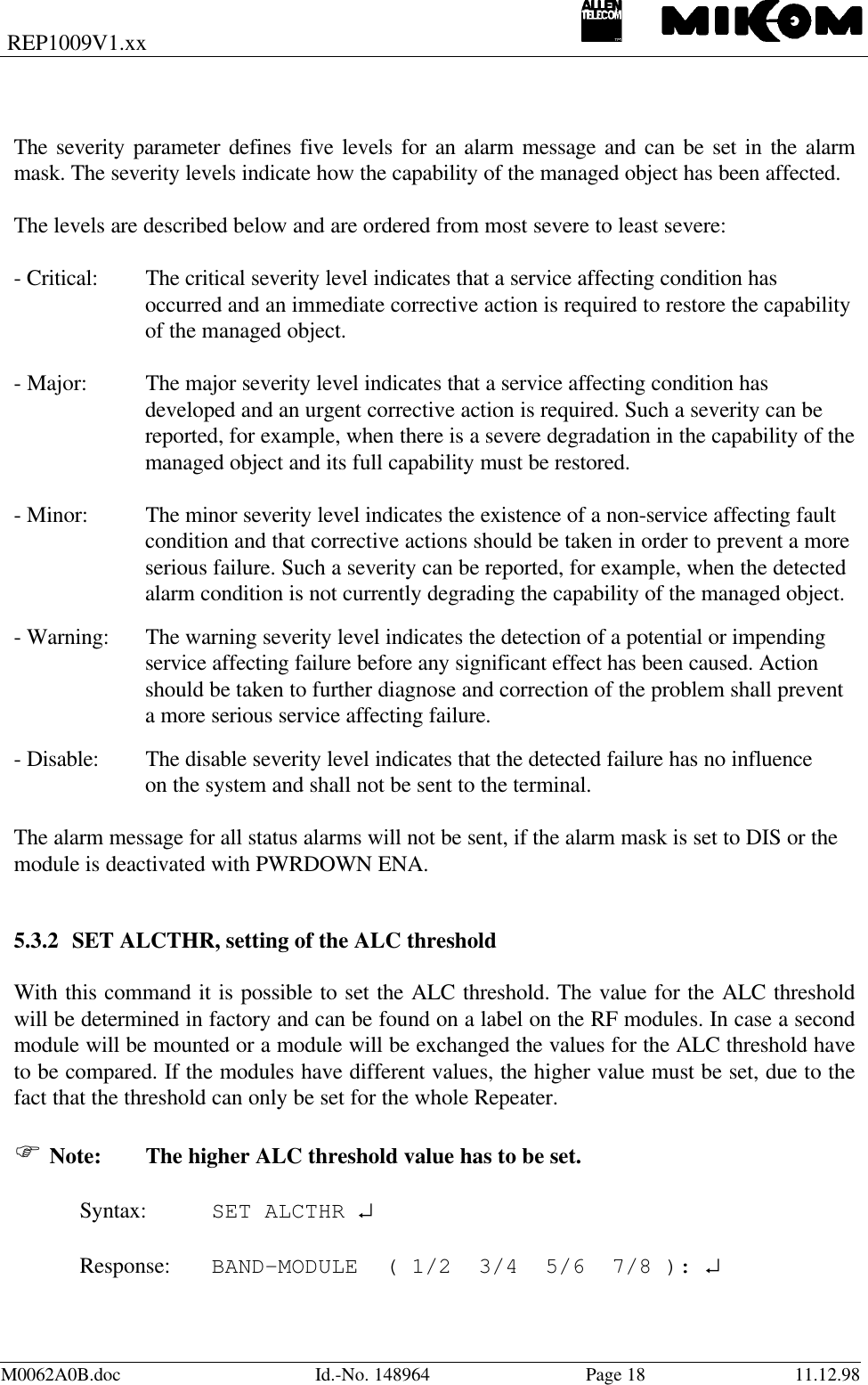
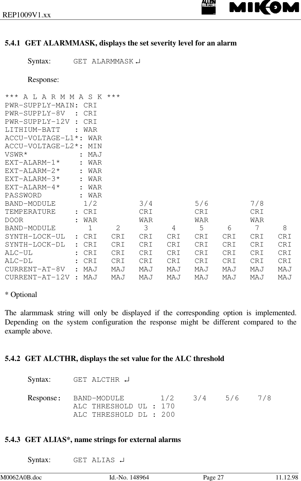
![REP1009V1.xxM0062A0B.doc Id.-No. 148964 Page 15 11.12.985 Description of the commandsAll available software commands are described in the following chapter.5.1 Instruction modesThere are four different types of commands:- SET commands - to change variable parameters- GET commands - to ask status of variable parameters- STATUS commands - to ask status of fixed parameters- ACTION commands - to perform certain actions5.2 ConventionsThe instruction is written in capital letters followed by selections in square brackets to beentered.SET NUM [x] [number] ↵↵The selections can be entered directly following the instruction e.g. SET NUM, but in caseonly SET NUM has been entered the computer queries for the missing information in aninteractive dialogue. As an example, x can be substituted by 1 or 2 corresponding to thewanted position in the telephone list and number can be substituted by the telephone number,which may consists of up to 25 characters.↵↵ stands for carriage return. It indicates to press the return key. If, in the above example, thetelephone number 2716 with priority 2 has to be entered the following command has to betyped:SET NUM 2 2716 ↵](https://usermanual.wiki/Andrew-Wireless-Innovations-Group/RPT-MR701.Software-manual/User-Guide-56377-Page-15.png)
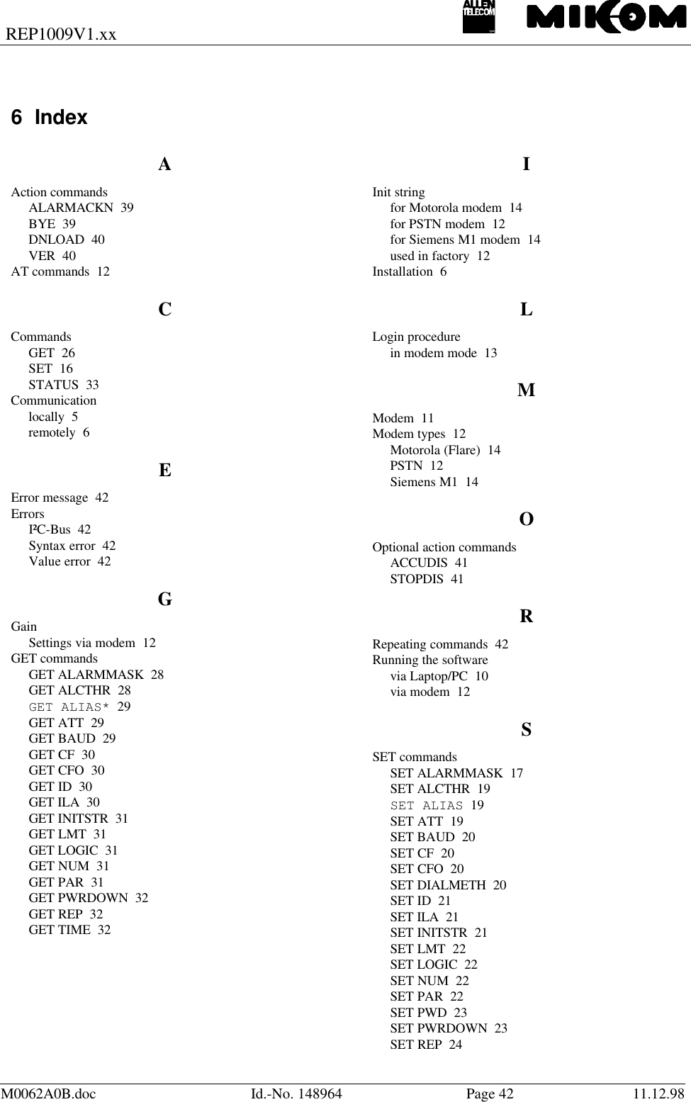
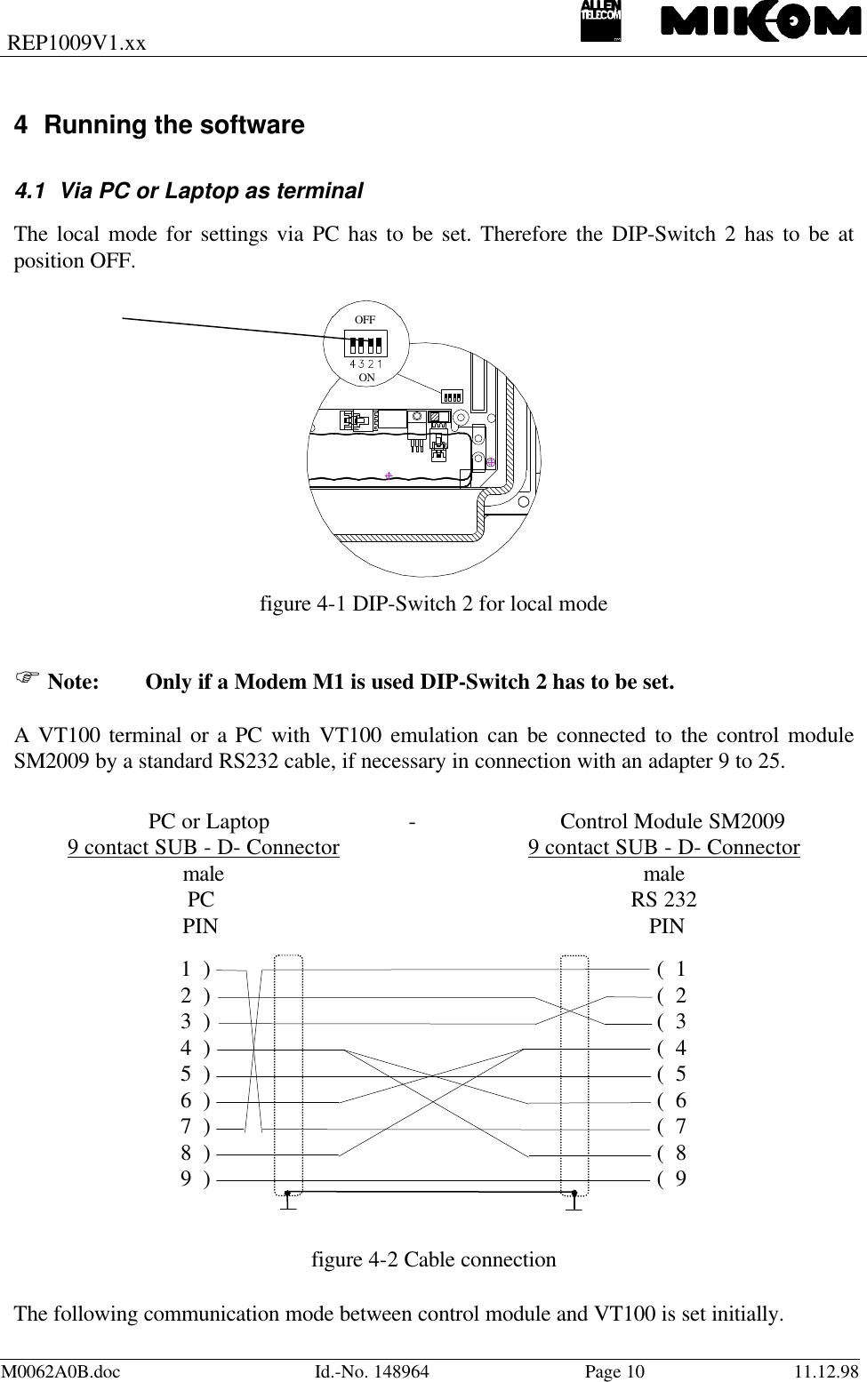
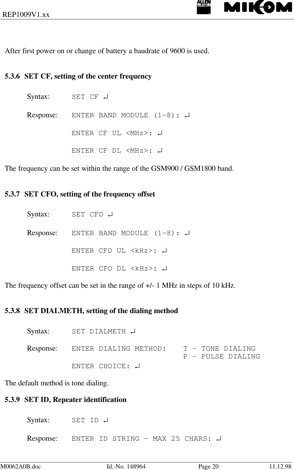
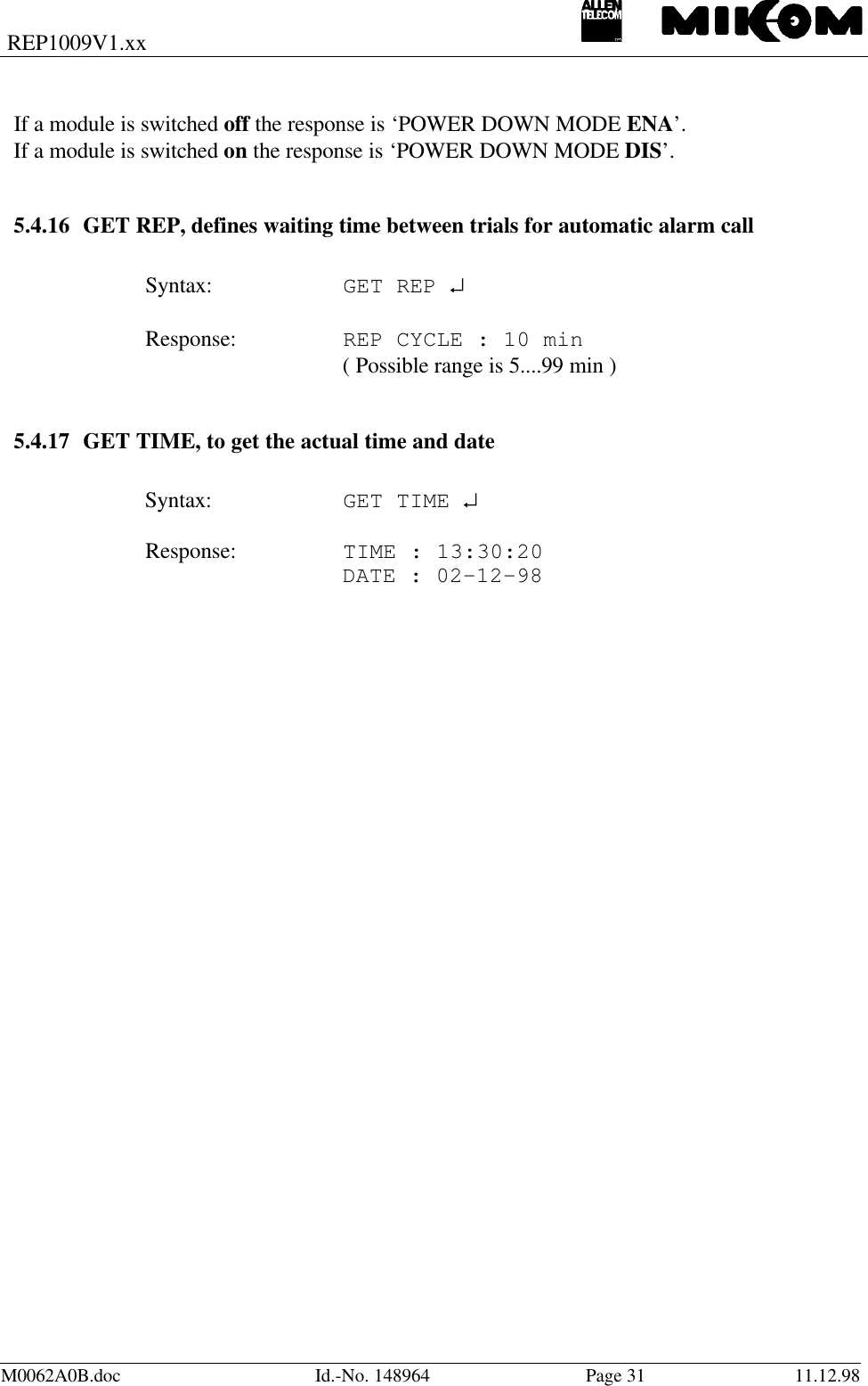
![REP1009V1.xxM0062A0B.doc Id.-No. 148964 Page 19 11.12.98ENTER MODE (UL or DL) : ↵ENTER ALC THRESHOLD 0 - 255 : ↵* * * C A U T I O N * * *THE FOLLOWING ACTION MAY CAUSE DAMAGE TO EXTERNAL HARDWAREPRESS <Y> + <CR> TO PERFORM CHANGEAllowed values are binary digits 0 ... 255. Default value is 255.5.3.3 SET ALIAS*, enter name strings for external alarms 1 ... 4Syntax:SET ALIAS ↵Response: ENTER ENTRY - 1 TRU 4: ↵ ENTER ALARM ACTIVE NAME STRING -MAX 30 CHARS : ↵ ENTER ALARM NON ACTIVE NAME STRING -MAX 30 CHARS: ↵You will be asked to enter a name string for the external alarms 1 ... 4. Two different namescan be defined, the first input is the name for the alarm active name and the second input is thename if the alarm is not active. Be aware the OMC needs appropriate key words forrecognising an alarm.5.3.4 SET ATT, sets attenuation in uplink or downlink pathSyntax : SET ATT ↵Response: ENTER BAND MODULE ( 1-8 ): ↵ENTER MODE ( UL or DL): ↵ENTER ATTENUATION: ↵You will be asked to enter the band module, mode and attenuation ( attenuation in dB, onlyvalues between 0 and 30 dB in steps of 2 dB ).5.3.5 SET BAUD, definition of baudrate usedSyntax: SET BAUD [ baudrate ] ↵Response: ENTER BAUDRATE – 1200, 2400, 4800 OR 9600:](https://usermanual.wiki/Andrew-Wireless-Innovations-Group/RPT-MR701.Software-manual/User-Guide-56377-Page-19.png)
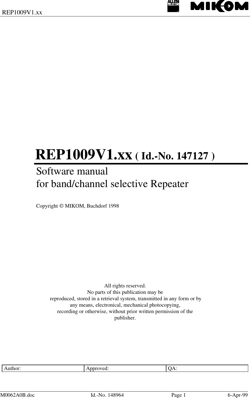
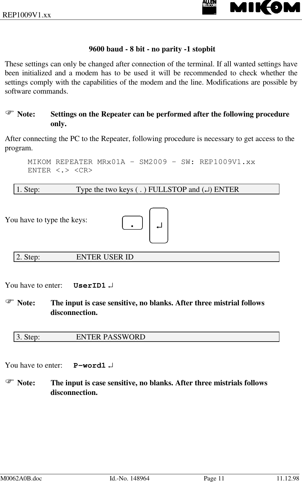
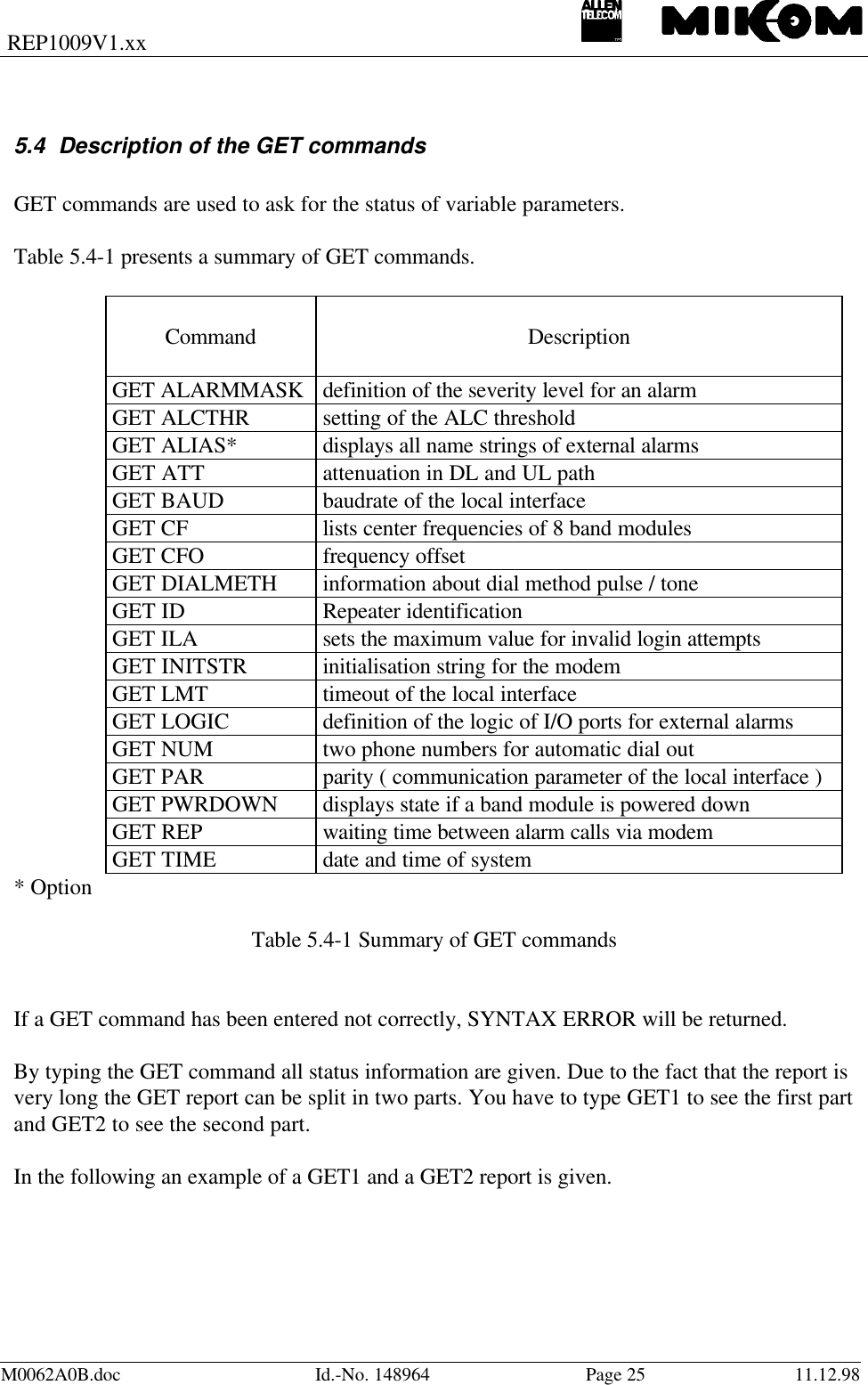
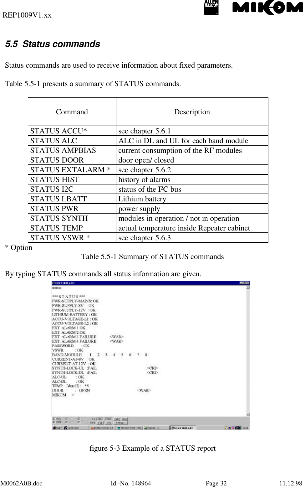
![REP1009V1.xxM0062A0B.doc Id.-No. 148964 Page 21 11.12.98where Repeater ID may be max. 25 symbols. All characters between 21 H and 7E H will beaccepted.If you skip this request, the default Repeater identification appears:Response: Repeater ID: MIKOM5.3.10 SET ILA, definition of a limit for invalid login attemptsSyntax: SET ILA ↵Response: ENTER VALUE : ↵The maximum allowed number of invalid login attempts have to be entered. Default value is 8.Setting range is 3 – 10 invalid login attempts.5.3.11 SET INITSTR, definition of a initialisation stringSyntax : SET INITSTR [Initstring] ↵Response: ENTER MODEM INIT STRING - MAX 60 CHARS: ↵where : [ Initstring ] is max. 60 symbols, 21 H to7E H is allowed.Initstring stands for the string stored in the modem for initialisation. It is defined in the manualof the modem.This stored INIT STRING was used for internal tests. In case no connection can be establishedcheck the local conditions and change the INIT STRING if necessaryF Note: Use upper case characters for entry.5.3.12 SET LMT, to change timeout for local maintenance interfaceSyntax: SET LMT ↵Response: ENTER VALUE: ↵](https://usermanual.wiki/Andrew-Wireless-Innovations-Group/RPT-MR701.Software-manual/User-Guide-56377-Page-21.png)
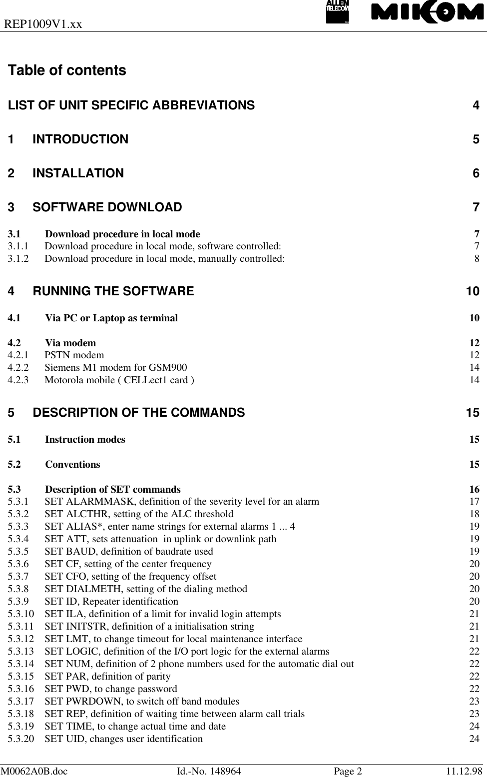
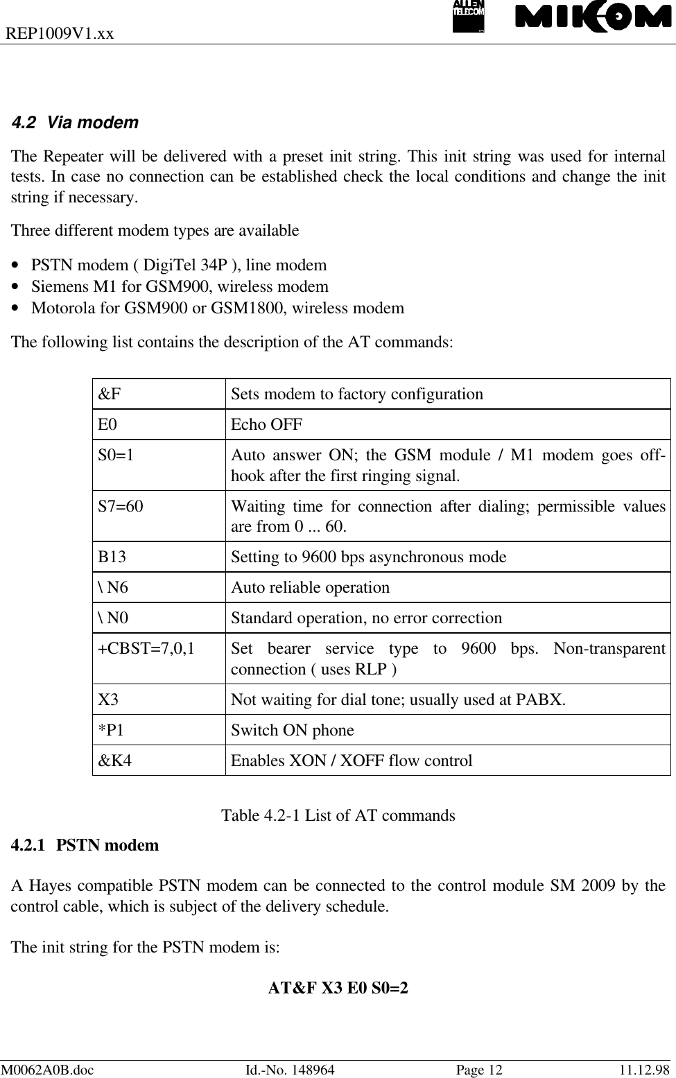
![REP1009V1.xxM0062A0B.doc Id.-No. 148964 Page 22 11.12.98Enter the local maintenance terminal timeout in minutes. LMT can be set in the range from 5 to99 minutes. Default value is 25 minutes.5.3.13 SET LOGIC, definition of the I/O port logic for the external alarmsWith this command it is possible to set the logic of the I/O ports for the external alarms. Thelogic can be changed for each alarm separately. The default settings of the I/O ports on thecontrol module are LLHH. This command is only available if the option “External Alarms” isactive.Syntax: SET LOGIC↵Response: ENTER ALARM LEVEL 1 (H/L): ↵ENTER ALARM LEVEL 2 (H/L): ↵ENTER ALARM LEVEL 3 (H/L): ↵ENTER ALARM LEVEL 4 (H/L): ↵5.3.14 SET NUM, definition of 2 phone numbers used for the automatic dial outSyntax: SET NUM ↵Response: ENTER ENTRY - 1 TRU 2: ↵ENTER PHONE NUMBER - MAX 25 CHARS: ↵Depending on the entry the numbers can have the priority 1 or 2 and max. 25 symbols areallowed.5.3.15 SET PAR, definition of paritySyntax : SET PAR [ parameter ] ↵Response: SELECT PARAMETER:7 BITS ODD PARITY - 17 BITS EVEN PARITY - 28 BITS NO PARITY - 3enter choice :After first power on or change of battery the interface module is preset to 8 Bits no parity.5.3.16 SET PWD, to change passwordSyntax: SET PWD ↵Response: ENTER ENTRY - 1 TRU 4: ↵](https://usermanual.wiki/Andrew-Wireless-Innovations-Group/RPT-MR701.Software-manual/User-Guide-56377-Page-22.png)
![REP1009V1.xxM0062A0B.doc Id.-No. 148964 Page 23 11.12.981 to 4 different passwords are possible. Users with password 1 or 2 have full access to theRepeater ( SET and GET commands possible). Users with password 3 or 4 have restrictedaccess ( only GET commands are available ).After typing this command you are requested to type the old password and finish with ↵.ENTER OLD PASSWORD: ----- ↵If the old password was correct you are requested to type the new password ( 1 - 10 symbolslong - letters, numbers, case sensitive ) and finish with ↵.ENTER NEW PASSWORD – MIN 1 MAX 10 CHARS: --------- ↵To store the new password the new password has to be typed again.ENTER NEW PASSWORD AGAIN TO CONFIRM : ---------- ↵PASSWORD HAS BEEN CHANGEDAfter first power on or change of batteries the default password ( to be determined for eachcustomer ) is used.5.3.17 SET PWRDOWN, to switch off band/channel modulesSyntax: SET PWRDOWN ↵Response: ENTER BAND MODULE ( 1-8 ): ↵SET POWER DOWN MODE: E - ENABLE POWER DOWN D - DISABLE POWER DOWNENTER CHOICE: ↵After typing the command you are asked to enter band module and the mode.Power down enable, means to switch off the band module.5.3.18 SET REP, definition of waiting time between alarm call trialsIf an alarm call is not acknowledged, the call will be repeated in time intervals, until it isacknowledged. The minimum value for the waiting time is 5 minutes.Syntax : SET REP [ cycle length ] ↵Response: ENTER CYCLE LENGTH IN MIN: ↵REP CYCLE: 10 MIN](https://usermanual.wiki/Andrew-Wireless-Innovations-Group/RPT-MR701.Software-manual/User-Guide-56377-Page-23.png)
![REP1009V1.xxM0062A0B.doc Id.-No. 148964 Page 24 11.12.98where : [ cycle length ] is the waiting time in minutes5 - 99 is allowed ( default: 10 min )5.3.19 SET TIME, to change actual time and dateSyntax: SET TIME ↵After carriage return the software queries line by line for the input as follows:ENTER YEAR < YYYY > (SKIP WITH CR):ENTER MONTH < MM > (SKIP WITH CR):ENTER DAY < DD > (SKIP WITH CR):ENTER HOURS < HH > (SKIP WITH CR):ENTER MINUTES < MM > (SKIP WITH CR):PRESS CR TO START5.3.20 SET UID, changes user identificationSyntax: SET UID ↵Response: ENTER ENTRY - 1 TRU 4: ↵1 to 4 user identification terms are possible. Users with user ID 1 or 2 have full access to theRepeater ( SET and GET commands possible). Users with ID 3 or 4 have restricted access( only GET commands are available ).After typing this command you are requested to type the old UID and finish with ↵.ENTER OLD USER ID: ----- ↵If the old UID was correct you are requested to type the new UID and finish with ↵.ENTER NEW USER ID - MIN 1 MAX 10 CHARS:: --------- ↵To store the new UID type it again.ENTER NEW USER ID AGAIN TO CONFIRM : ---------- ↵USER ID HAS BEEN CHANGEDAfter first power on or changing of the Lithium battery the default password ( to bedetermined for each customer ) will be loaded.](https://usermanual.wiki/Andrew-Wireless-Innovations-Group/RPT-MR701.Software-manual/User-Guide-56377-Page-24.png)
![REP1009V1.xxM0062A0B.doc Id.-No. 148964 Page 28 11.12.98Response: NAME STRINGS FOR ALARMSEXT. ALARM 1 ACTIVE – EXT. ALARM 1 FAILUREEXT. ALARM 1 NON ACTIVE – EXT. ALARM 1 OKEXT. ALARM 2 ACTIVE – EXT. ALARM 2 FAILUREEXT. ALARM 2 NON ACTIVE – EXT. ALARM 2 OKEXT. ALARM 3 ACTIVE – EXT. ALARM 3 FAILUREEXT. ALARM 3 NON ACTIVE – EXT. ALARM 3 OKEXT. ALARM 4 ACTIVE – EXT. ALARM 4 FAILUREEXT. ALARM 4 NON ACTIVE – EXT. ALARM 4 OKor UPS ALARM ACTIVEUPS NON ACTIVEBATTERY VOLTAGE LOWBATTERY VOLTAGE OKUPS DOOR OPENUPS DOOR CLOSEDBATTERY DOOR OPENBATTERY DOOR CLOSED5.4.4 GET ATT, gain settingSyntax: GET ATT ↵Response:BAND-MODULE 1 2 3 4 5 6 7 8CF UL [MHz] 833.5CF DL [MHz] 947.5CFO UL [kHz] 0CFO DL [kHz] 0ATT UL [dB] 0ATT DL [dB] 4 5.4.5 GET BAUD, baudrateSyntax: GET BAUD ↵Response: LOCAL - INTERFACE : 9600 bps, 8 bits, NO PARITY( also 4800, 2400 or 1200 are possible)5.4.6 GET CF, set centre frequency in the GSM900 / GSM1800 bandSyntax: GET CF ↵Response, e.g. for the GSM900 system:](https://usermanual.wiki/Andrew-Wireless-Innovations-Group/RPT-MR701.Software-manual/User-Guide-56377-Page-28.png)
![REP1009V1.xxM0062A0B.doc Id.-No. 148964 Page 29 11.12.98BAND MODULE 1 2 3 4 5 6 7 8CF UL [MHz] 833.5 0CF DL [MHz] 880.5 0CFO UL [kHz] 0 0CFO DL [kHz] 0 0ATT UL [dB] 0 0ATT DL [dB] 4 05.4.7 GET CFO, frequency offsetSyntax: GET CFO ↵Response, e.g. for the GSM900 system:BAND MODULE 1 2 3 4 5 6 7 8CF UL [MHz] 833.5 0CF DL [MHz] 880.5 0CFO UL [kHz] 0 0CFO DL [kHz] 0 0ATT UL [dB] 0 0ATT DL [dB] 4 05.4.8 GET ID, Repeater identificationSyntax: GET ID ↵Response: REPEATER ID: MIKOM5.4.9 GET ILA, displays stored number of invalid login attemptsSyntax: GET ILA ↵ Response: ILA Invalid login attempts:5.4.10 GET INITSTR, displays the string which is used to initialize the modemSyntax: GET INITSTR ↵Response: If a Hayes compatible modem is used:MODEM INITSTRING: AT&F &K4 E0 S0=2](https://usermanual.wiki/Andrew-Wireless-Innovations-Group/RPT-MR701.Software-manual/User-Guide-56377-Page-29.png)
![REP1009V1.xxM0062A0B.doc Id.-No. 148964 Page 30 11.12.985.4.11 GET LMT, timeout for local interfaceSyntax: GET LMT ↵Response: TIMEOUT FOR LMT : 25 min5.4.12 GET LOGIC, displays the logic of the I/O portsSyntax: GET LOGIC ↵Response: EXT. ALARM LEVEL: L L H H5.4.13 GET NUM, displays stored phone numbersSyntax : GET NUM [ x ] ↵where: [ x ] is priority in the list, may be 1 or 2orSyntax: GET NUM ↵Response: PHONE NUMBER 1: 0000PHONE NUMBER 2: 00005.4.14 GET PAR, modem paritySyntax: GET PAR ↵Response: LOCAL-INTERFACE : 9600 bps, 8 bits, NO PARITY5.4.15 GET PWRDOWN, displays power down status of the modulesSyntax: GET PWRDOWN ↵Response: BAND-MODULE 1 2 3 4 5 6 7 8PWR DOWN MODE: ENA DISThis command displays the status of the band modules.](https://usermanual.wiki/Andrew-Wireless-Innovations-Group/RPT-MR701.Software-manual/User-Guide-56377-Page-30.png)
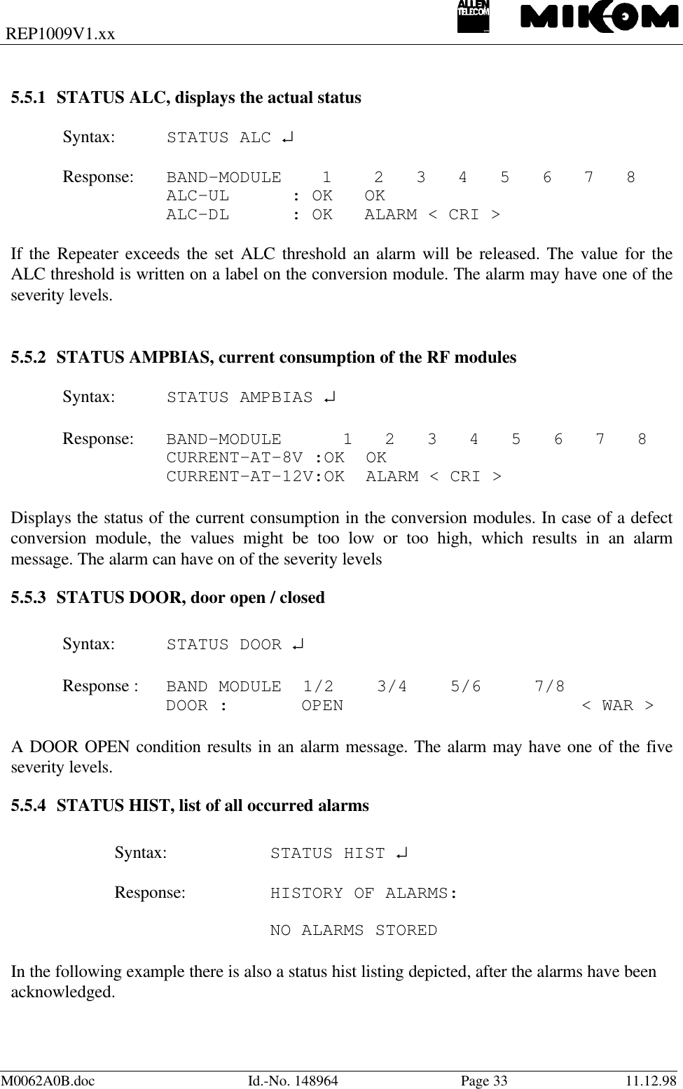
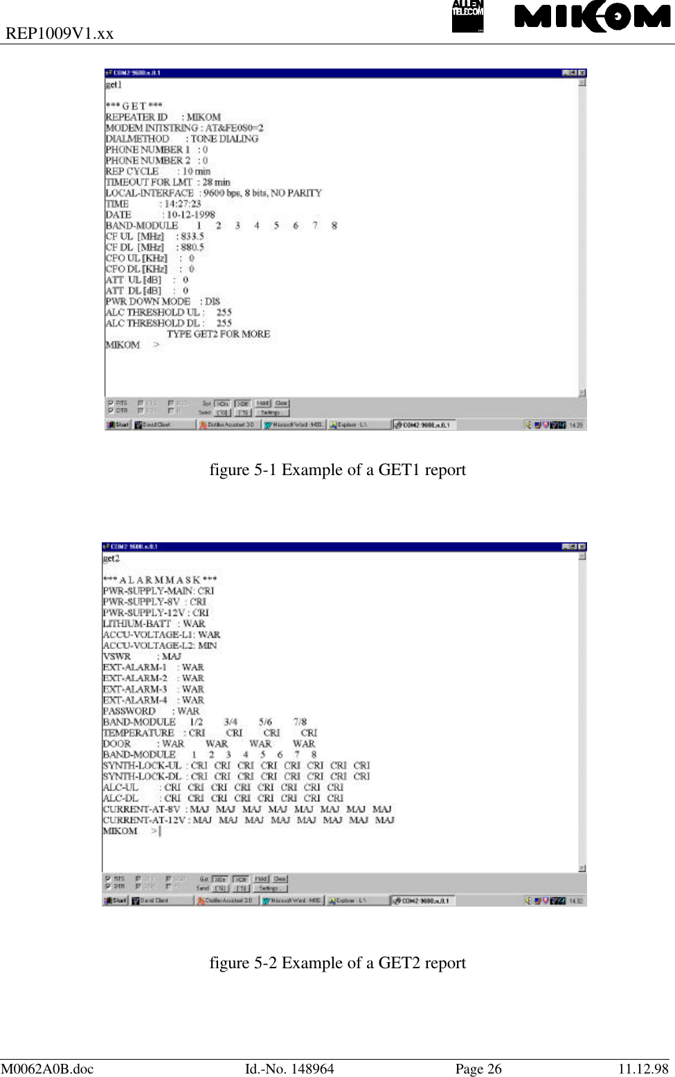
![REP1009V1.xxM0062A0B.doc Id.-No. 148964 Page 36 11.12.98Response: BAND-MODULE 1 2 3 4 5 6 7 8SYNTH-LOCK-UL: OK OKSYNTH-LOCK-DL: OK FAIL < CRI >A defect synthesizer indicates that the conversion module has to be exchanged.5.5.9 STATUS TEMP, temperatureSyntax: STATUS TEMP ↵Response: BAND-MODULE 1/2 3/4 5/6 7/8TEMP [deg C] : 56In case 4 Repeaters are installed, the temperature will be displayed for each unit with aresolution of 1° C. The accuracy is ± 2° C.An alarm will be released at a temperature ≥ +75° CThe response then is: TEMPERATURE = 76 °C, Temperature Alarm - Stage 1Another alarm will be released at a temperature ≥ +90° C.The response then is: TEMPERATURE = 91 °C, Temperature Alarm - Stage 2RF stages are in POWER DOWN mode as long as the temperature alarm stage 2 exists andwill be switched on again if the temperature is below +85° C.](https://usermanual.wiki/Andrew-Wireless-Innovations-Group/RPT-MR701.Software-manual/User-Guide-56377-Page-36.png)