Andrew Wireless System UEBL2323 ION-B Extension Booster for cellular systems User Manual
Andrew Wireless System ION-B Extension Booster for cellular systems
UserManual.wiki
>
Andrew Wireless System
>
UEBL2323 User Manual
>
user manual
Contents
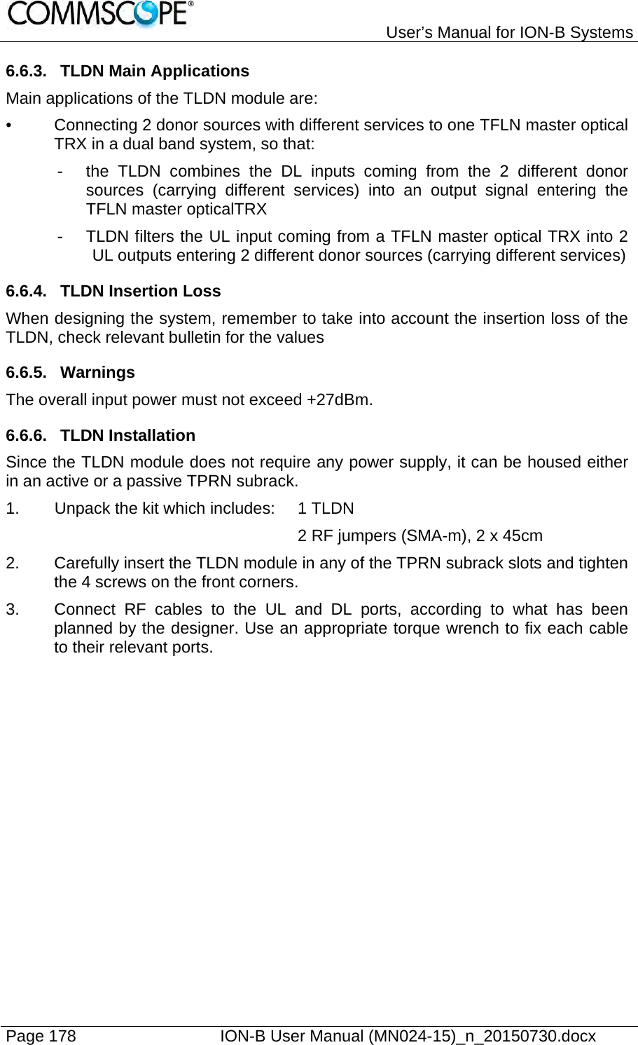
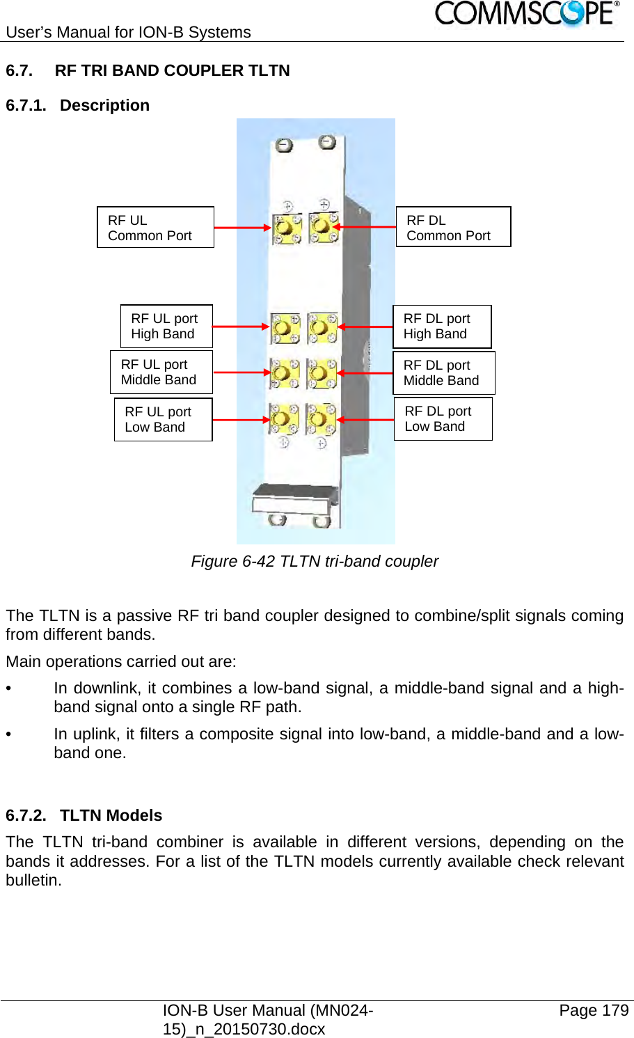
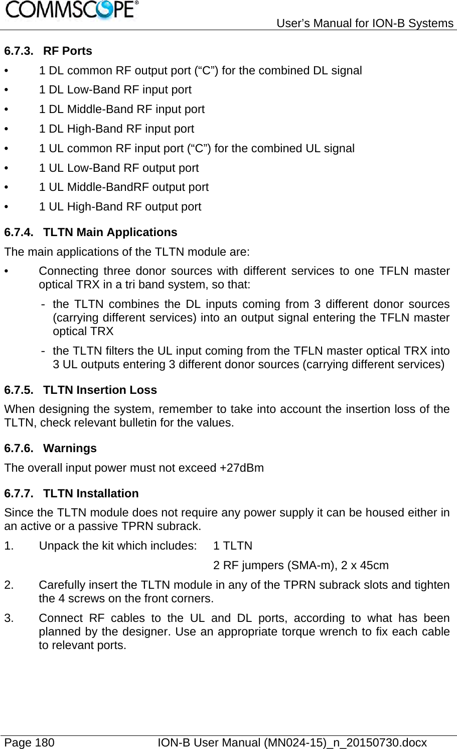
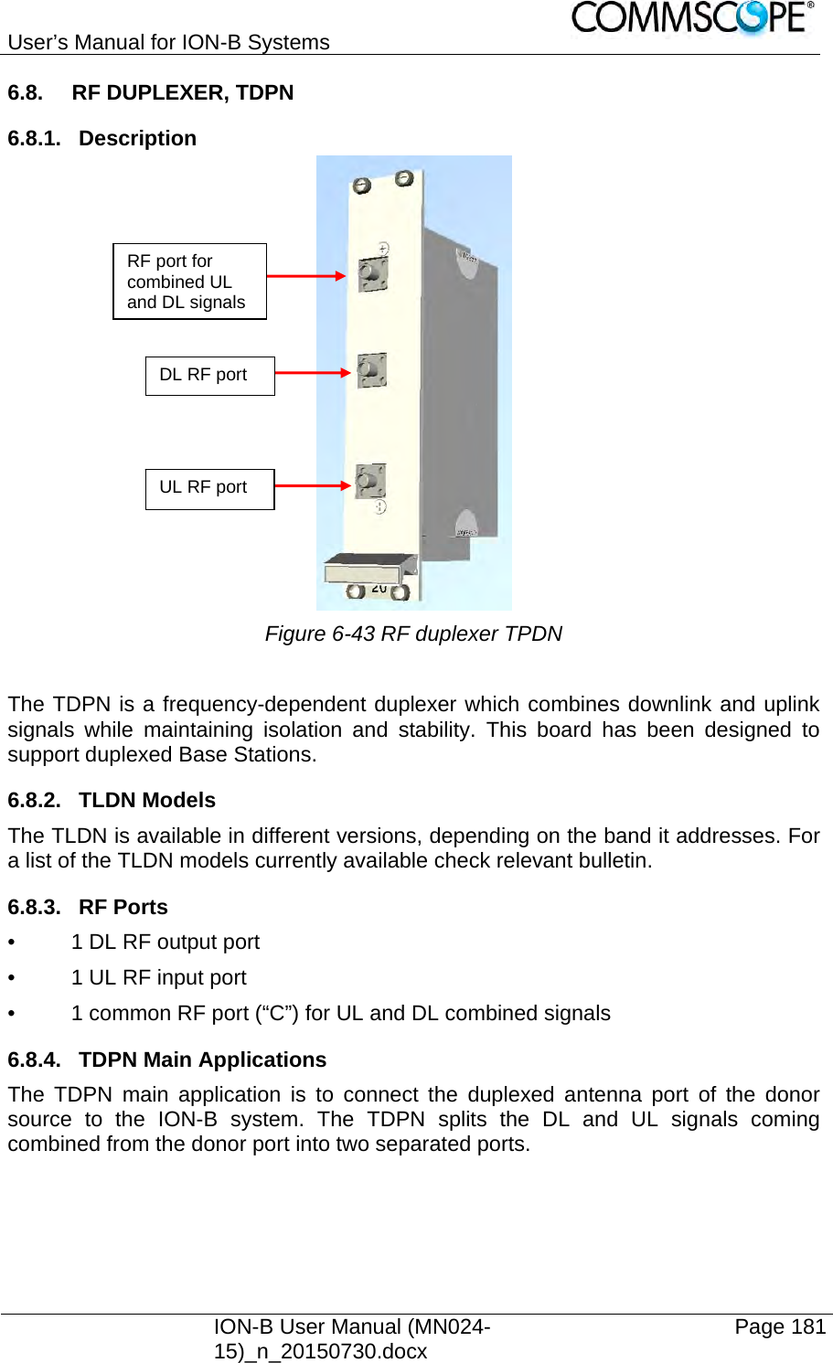
1.
Installation Instruction
2.
user manual
user manual
Navigation menu
Upload a User Manual
Namespaces
Wiki Guide
HTML
PDF
Info
Views
User Manual
Discussion / Help
Navigation
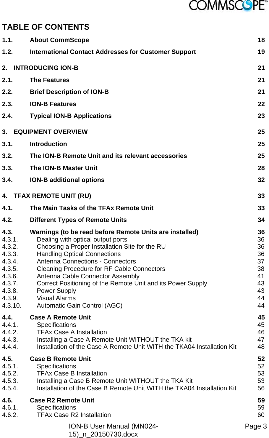

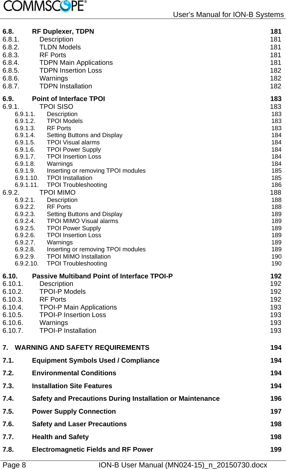


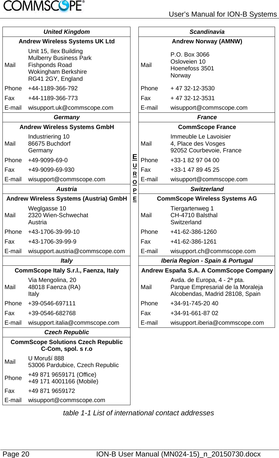
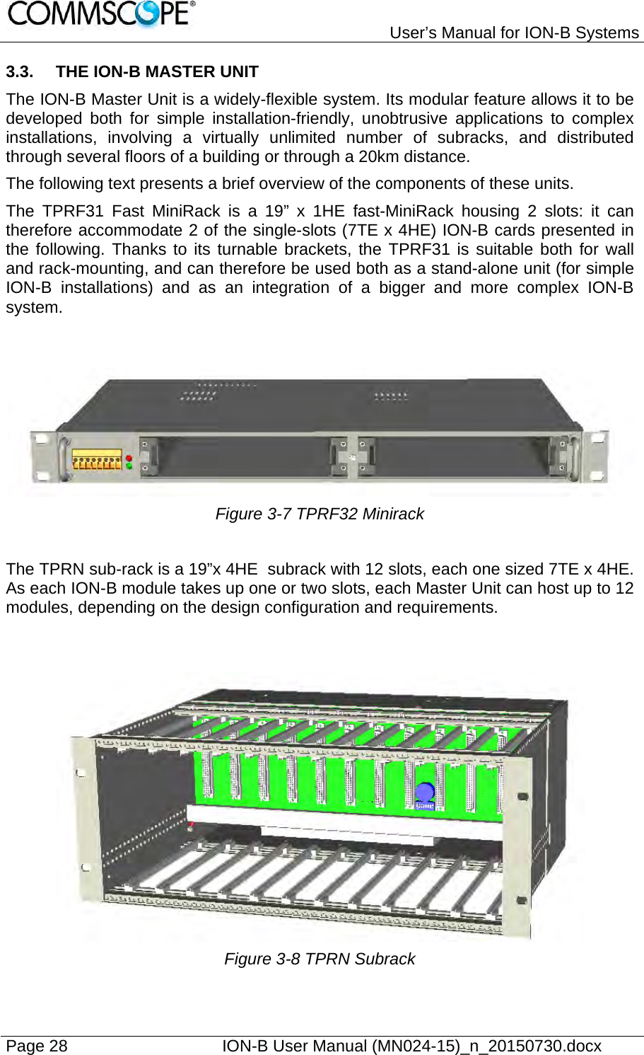
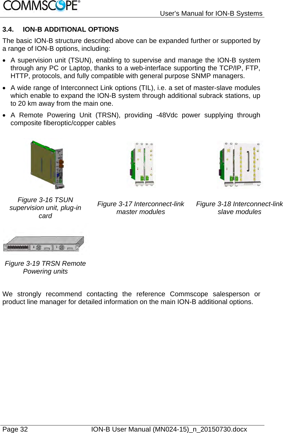
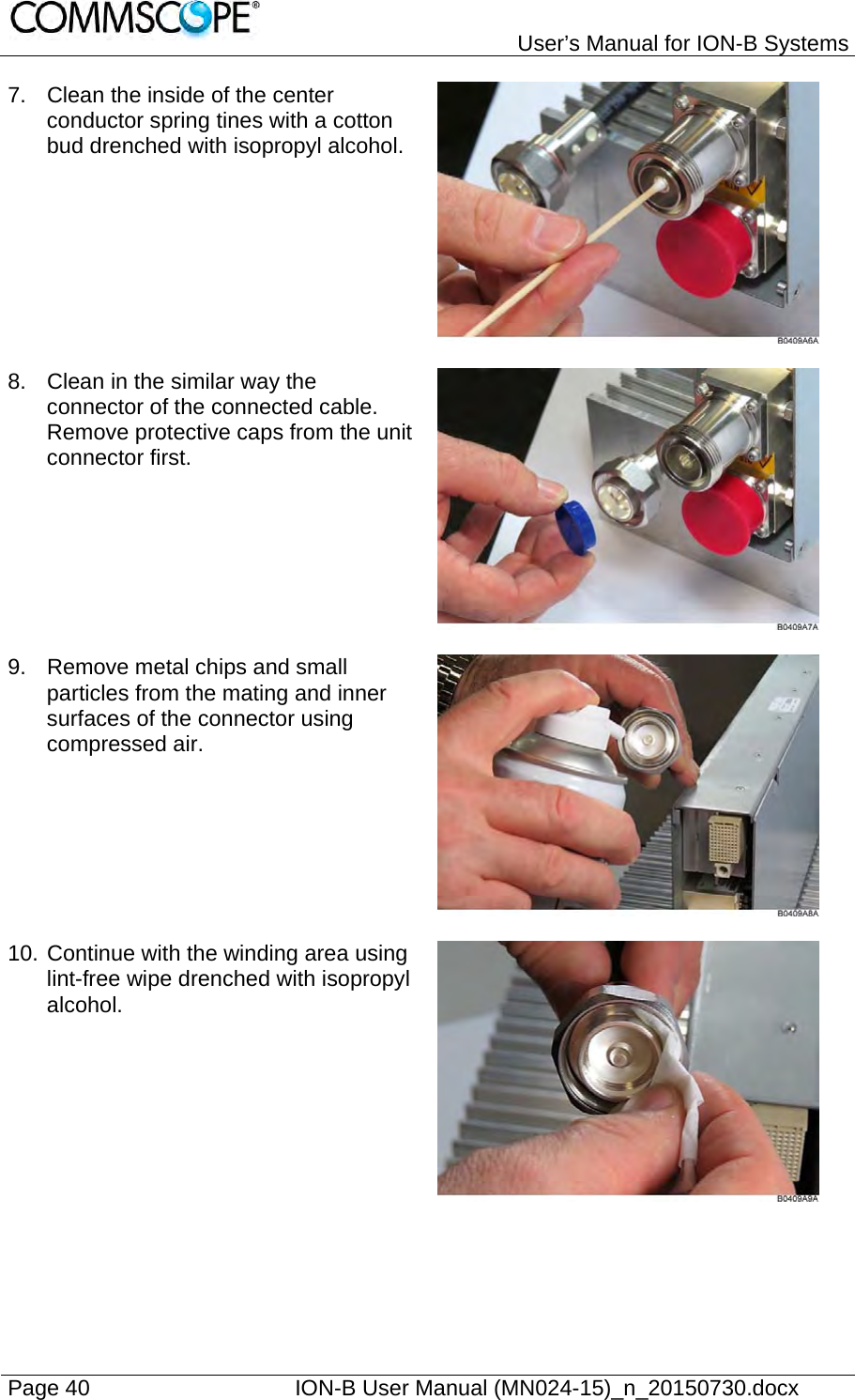
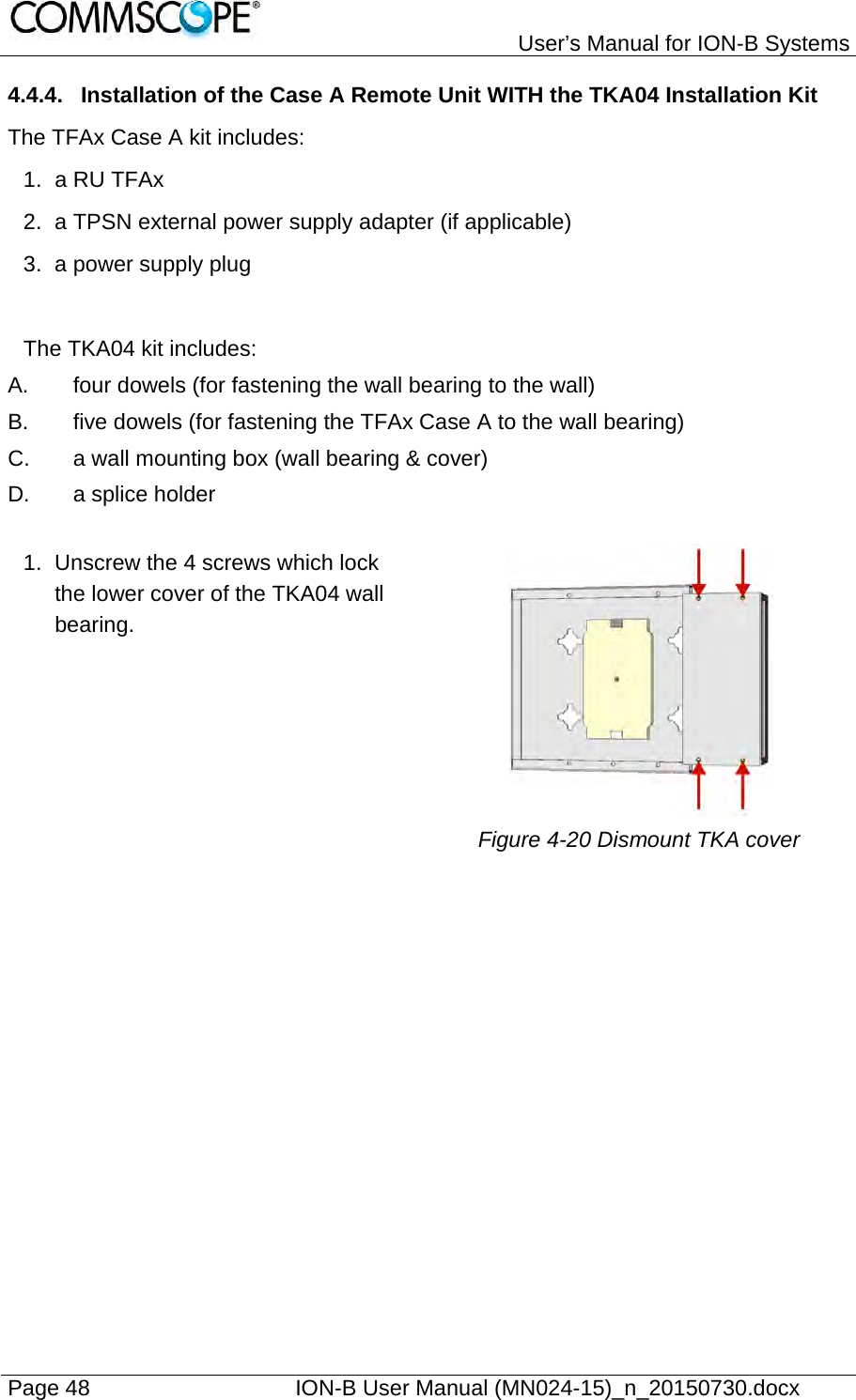
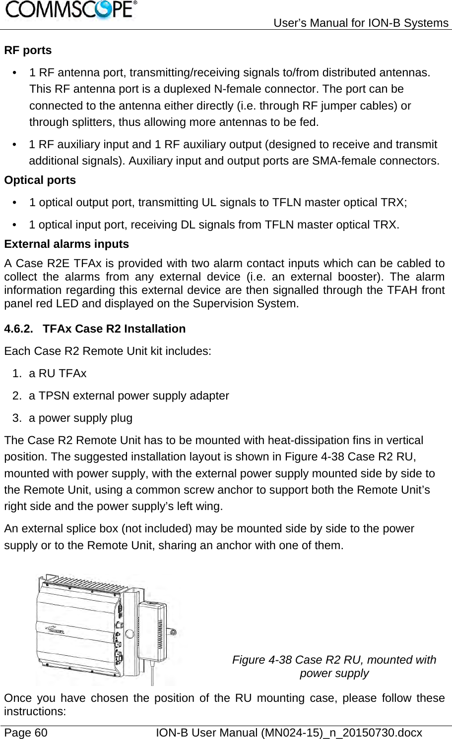
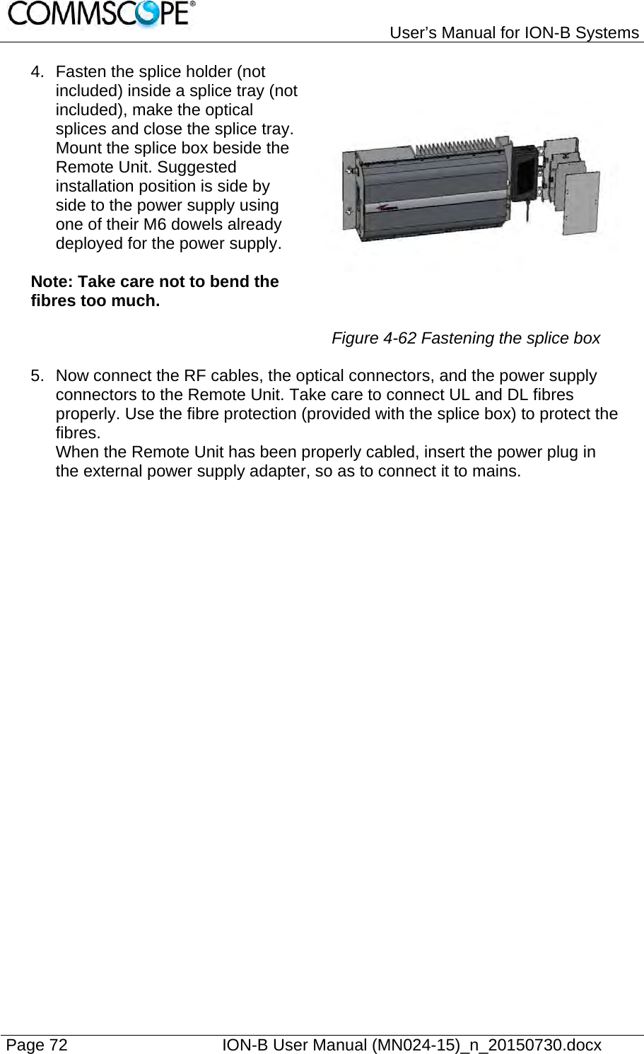
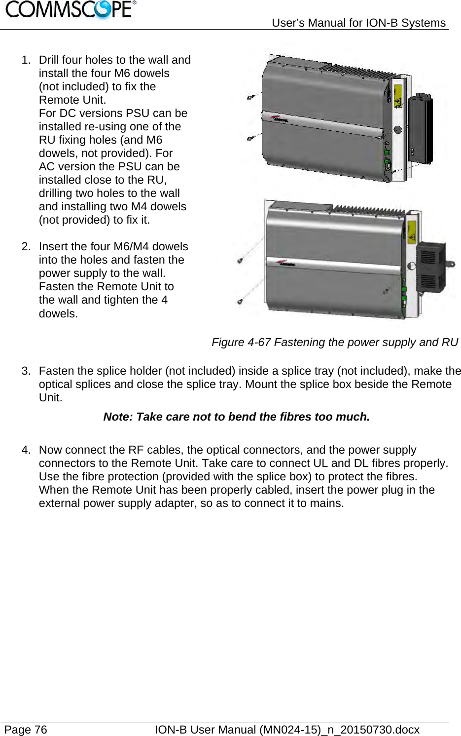
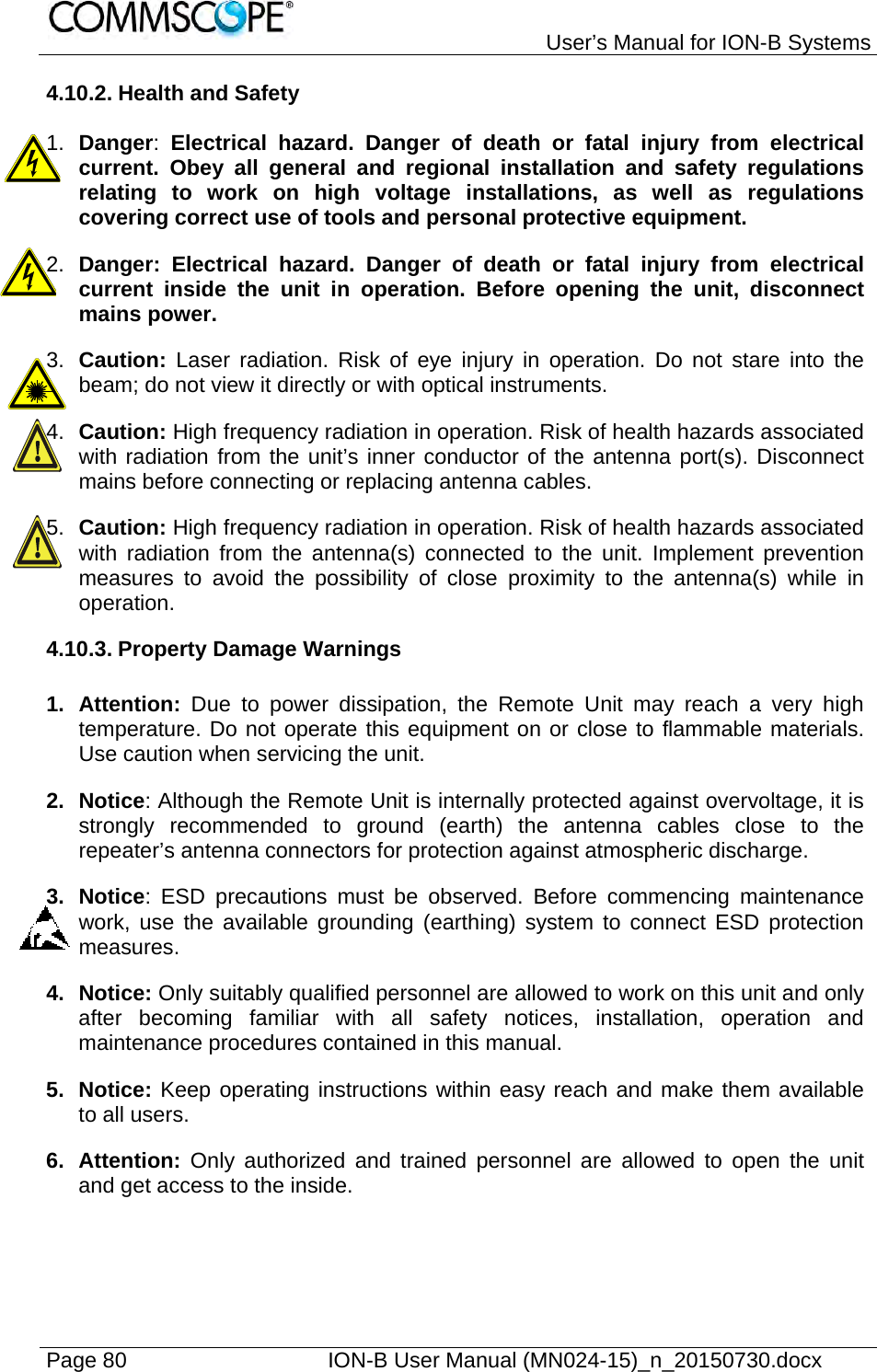
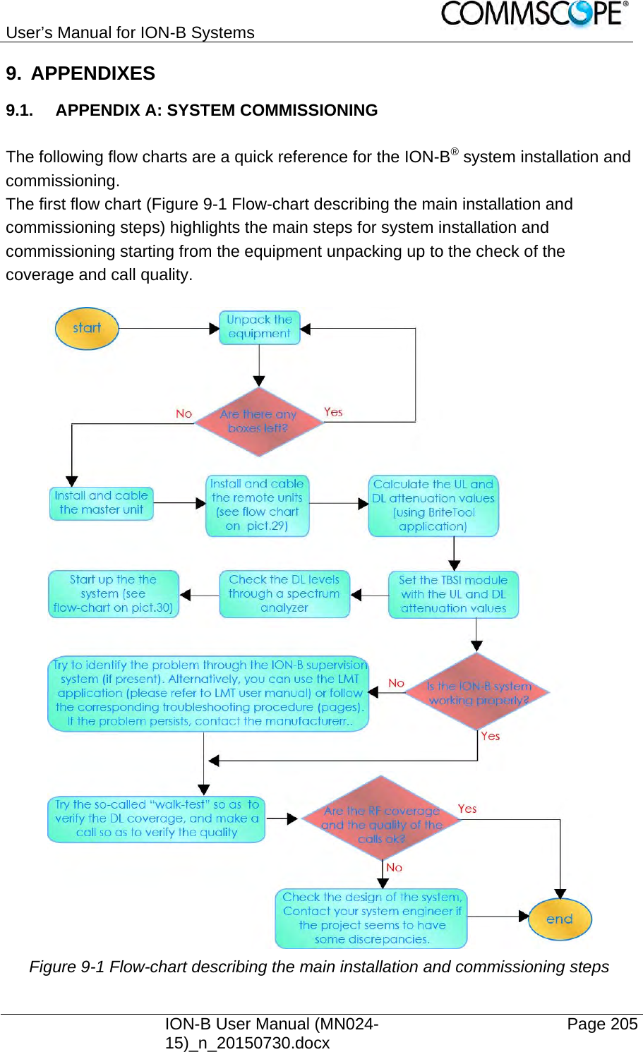
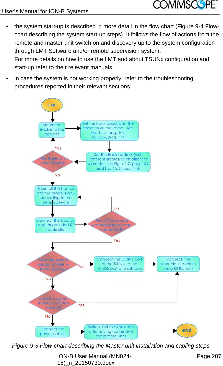
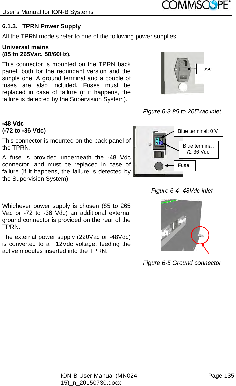
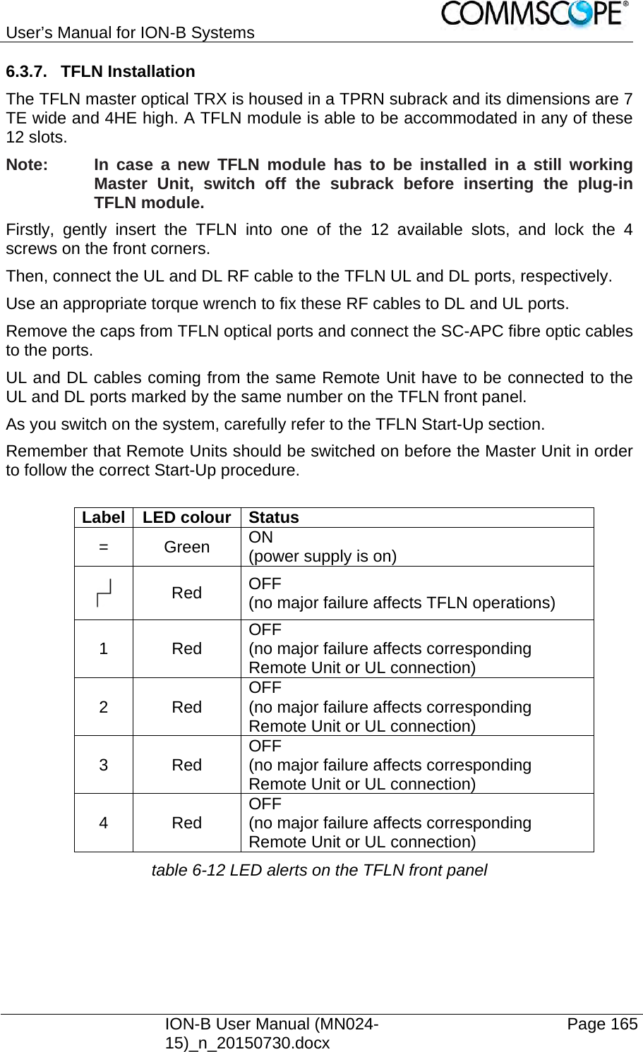
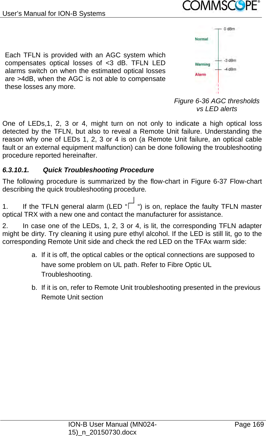
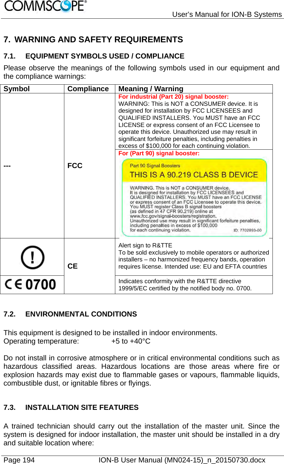
![User’s Manual for ION-B Systems ION-B User Manual (MN024-15)_n_20150730.docx Page 81 7. Notice: Read and obey all the warning labels attached to the unit. Make sure that all warning labels are kept in a legible condition. Replace any missing or damaged labels. 8. Notice: Only license holders for the respective frequency range are allowed to operate this unit. 9. Notice: Make sure the repeater settings are correct for the intended use (refer to the manufacturer product information) and regulatory requirements are met. Do not carry out any modifications or fit any spare parts, which are not sold or recommended by the manufacturer. 4.10.4. Compliance 1. Notice: For installations which have to comply with European EN50385 exposure compliance requirements, the following Power Density limits/guidelines (mW/cm²) according to ICNIRP are valid: o 0.2 for frequencies from 10 MHz to 400 MHz o F (MHz) / 2000 for frequencies from 400 MHz to 2 GHz o 1 for frequencies from 2 GHz to 300 GHz 2. Notice: For installations, which have to comply with FCC RF exposure requirements, the antenna selection and installation must be completed in a way to ensure compliance with those FCC requirements. Depending on the RF frequency, rated output power, antenna gain, and the loss between the repeater and antenna, the minimum distance D to be maintained between the antenna location and human beings is calculated according to this formula: ]/[][][24cmmWmWcmPDPD where P (mW) is the radiated power at the antenna, i.e. the max. rated repeater output power in addition to the antenna gain minus the loss between the repeater and the antenna. PD (mW/cm²) is the allowed Power Density limit acc. to 47 CFR 1.1310 (B) for general population / uncontrolled exposures which is o F (MHz) / 1500 for frequencies from 300MHz to 1500MHz o 1 for frequencies from 1500MHz to 100,000MHz RF exposure compliance may need to be addressed at the time of licensing, as required by the responsible FCC Bureau(s), including antenna co-location requirements of 1.1307(b)(3).](https://usermanual.wiki/Andrew-Wireless-System/UEBL2323.user-manual/User-Guide-2794507-Page-81.png)
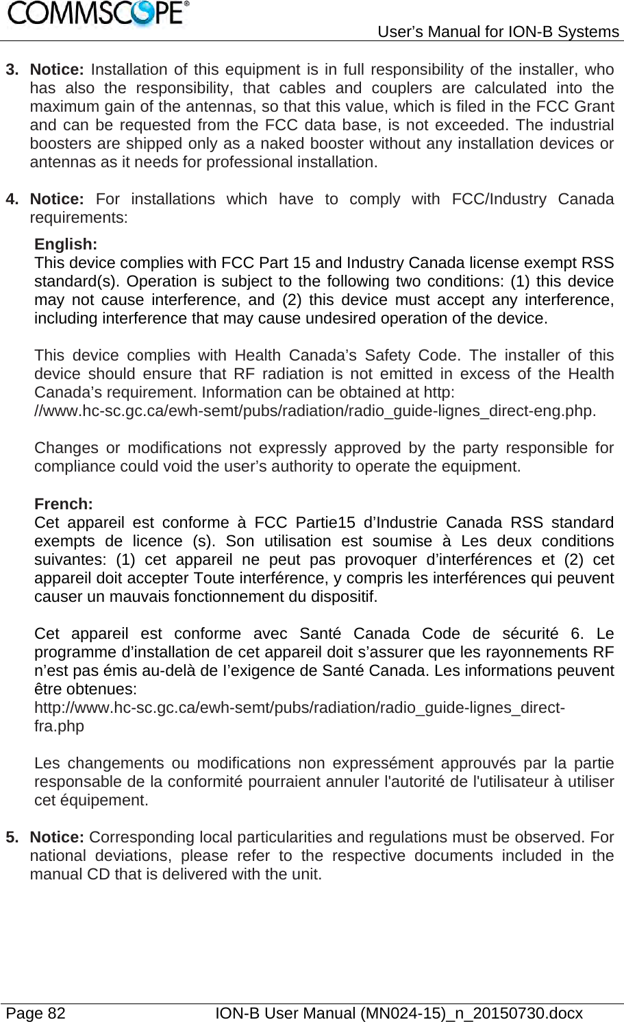

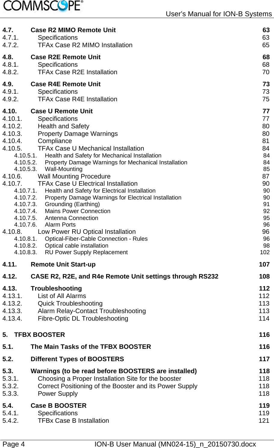
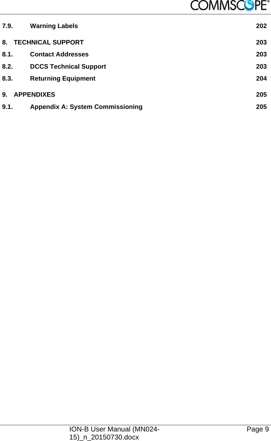
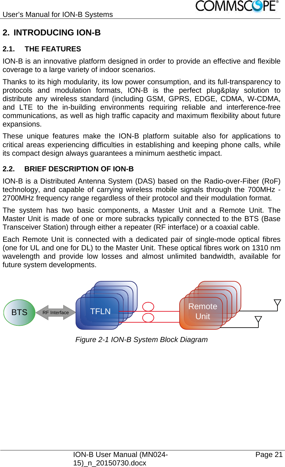
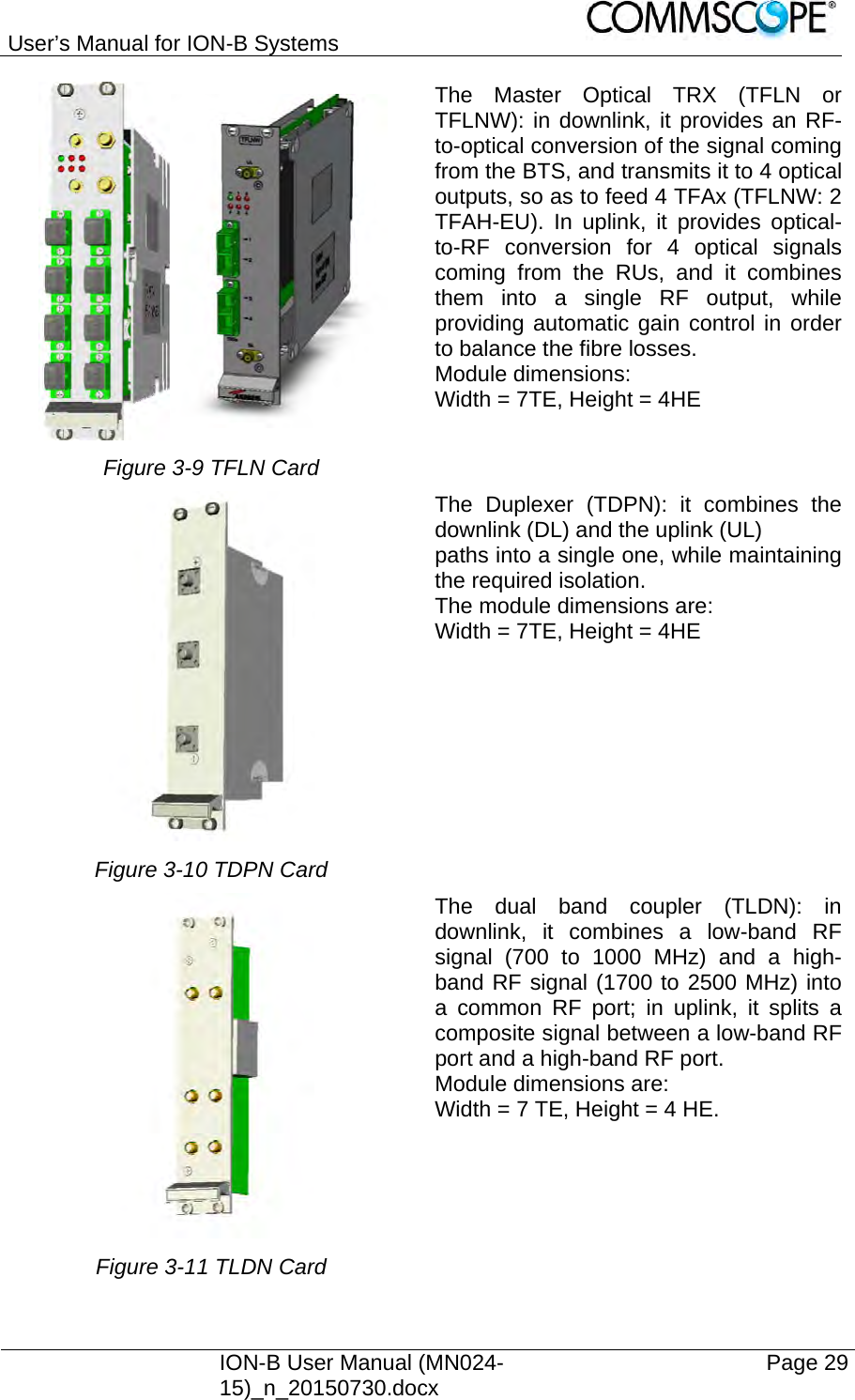
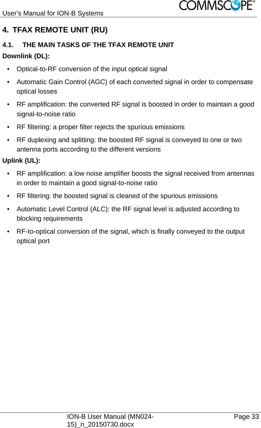
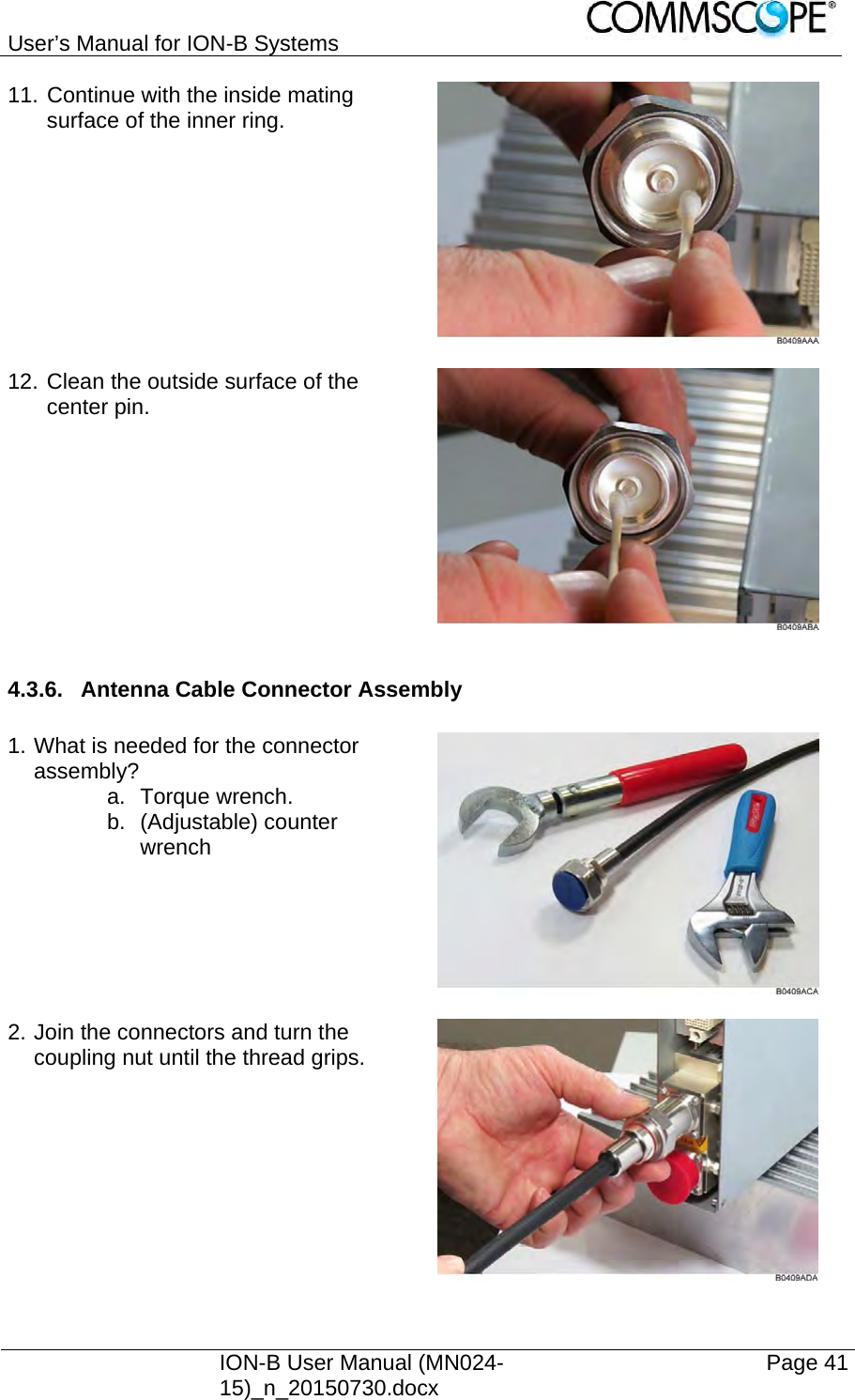
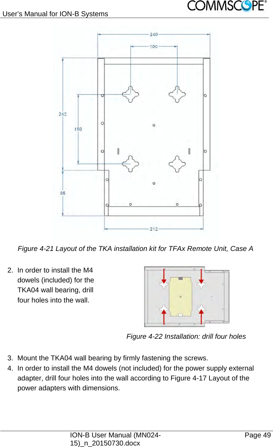
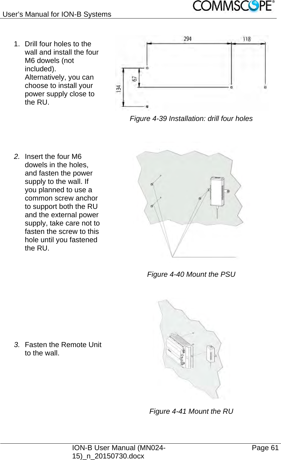
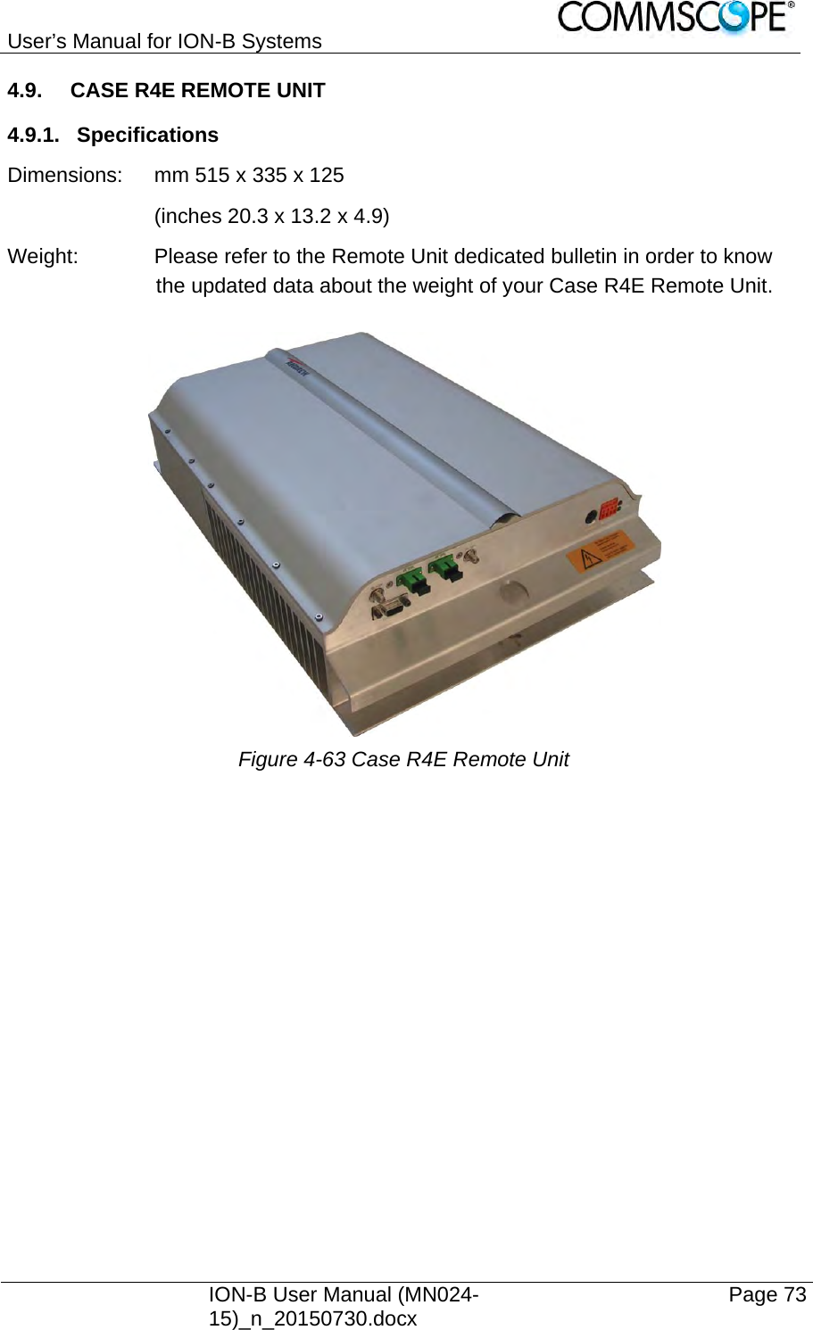
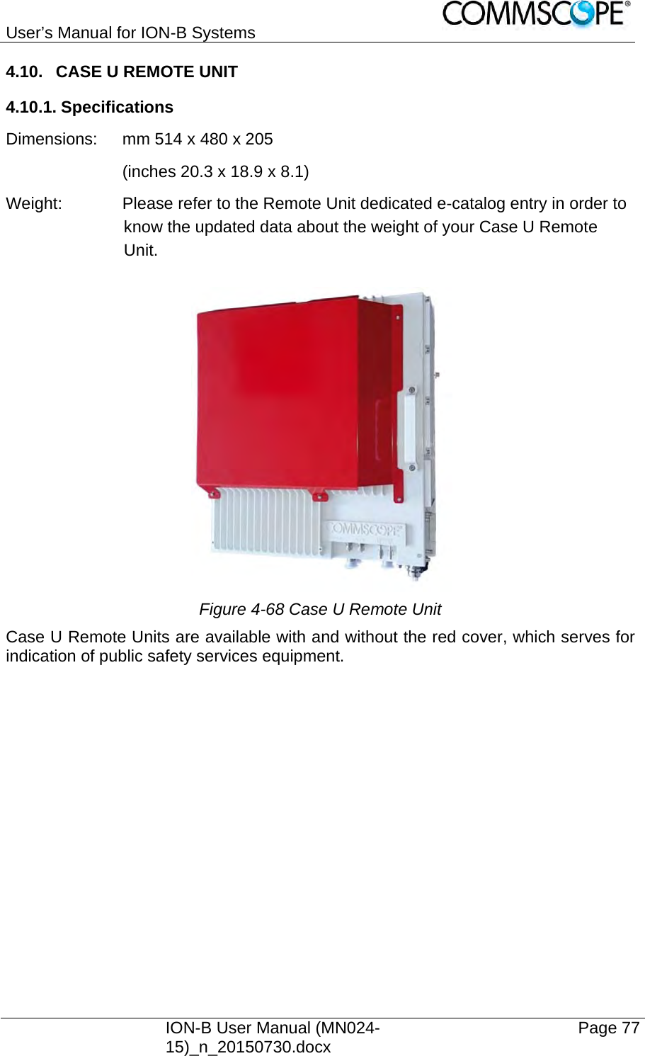
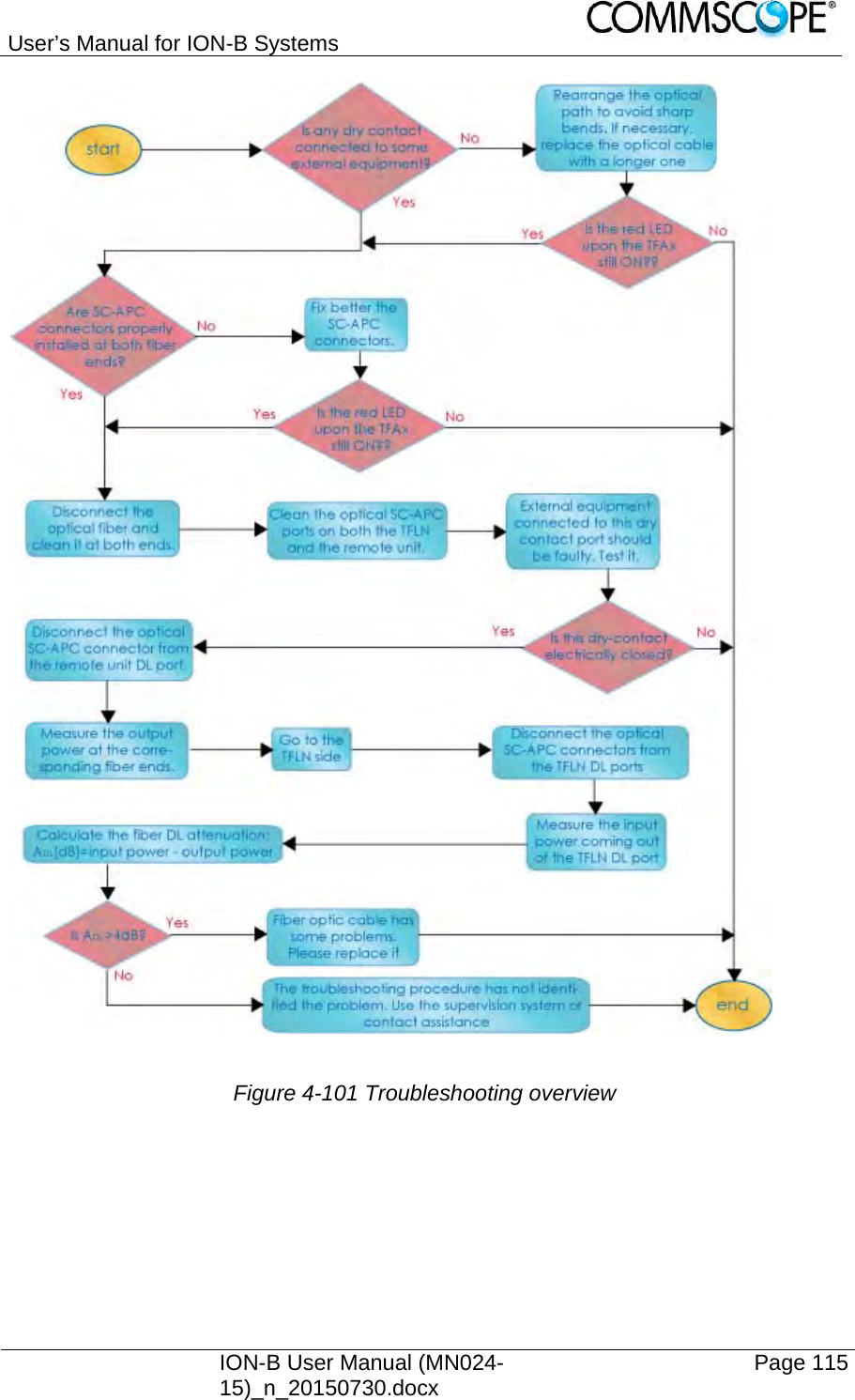
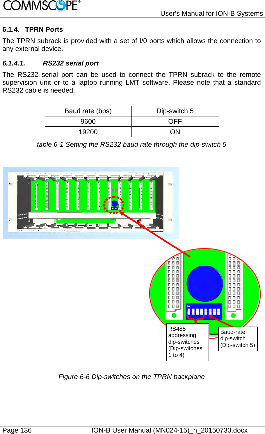
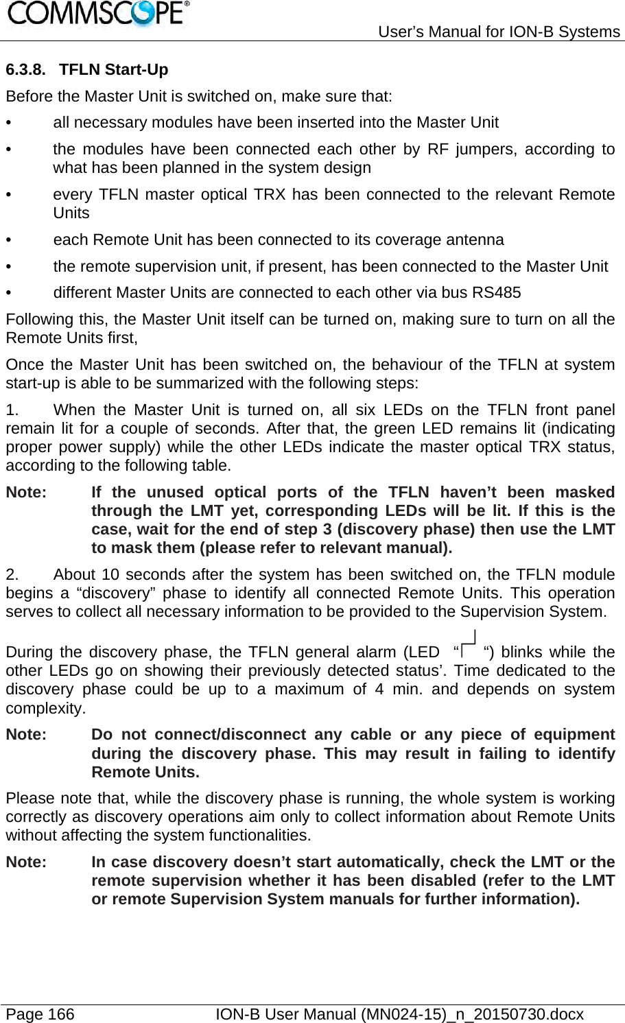
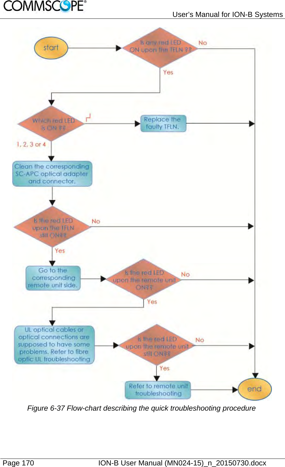
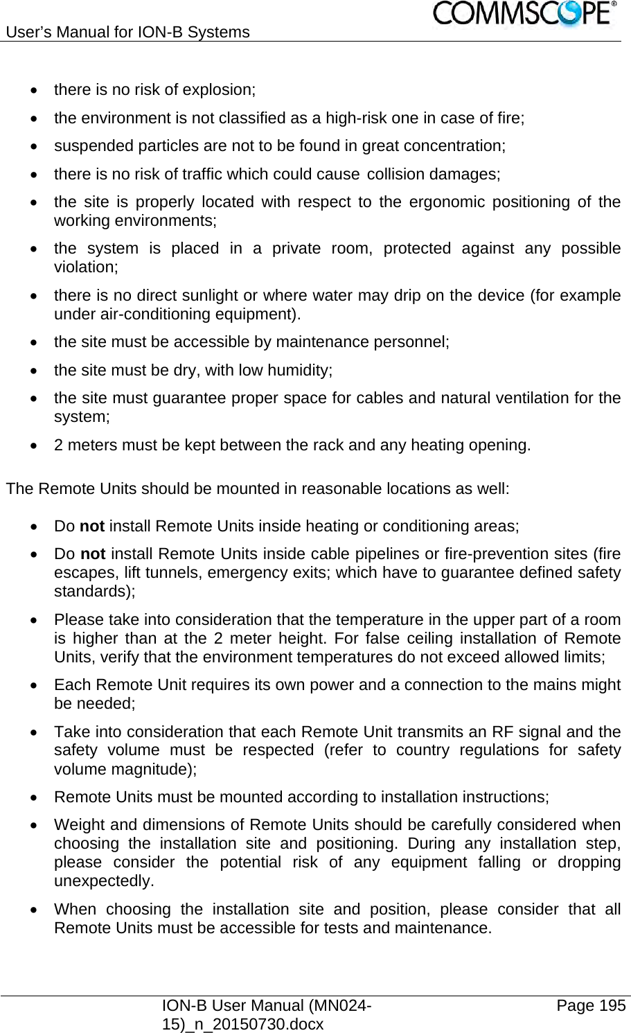
![User’s Manual for ION-B Systems Page 114 ION-B User Manual (MN024-15)_n_20150730.docx 4.13.4. Fibre-Optic DL Troubleshooting 1. Check to see if there are any points in which fibres are experiencing a short radius of curvature. In these cases, rearrange the optical path in order to avoid sharp bends (if necessary, replace the optical cable with a longer one). 2. Check to see if SC-APC connectors are properly installed at both fibre ends. In case they are not, re-plug the SC-APC connectors to adapters. 3. Disconnect the optical fibre and clean it at both ends, then clean the SC-APC ports on both the TFLN and the RU. Re-connect the fibre to relevant ports after cleaning. 4. Disconnect the optical SC-APC connector from the Remote Unit’s DL port, and measure the output power POUT(DL) at the corresponding fibre end. Then, go to the TFLN side, disconnect the optical SC-APC connector from the TFLN DL port and measure the input power PIN(DL) coming out of the TFLN DL port. Calculate the DL fibre attenuation ADL as ADL [dB] = PIN(DL) – POUT(DL): a) If ADL > 4dB, then there are problems with the fibre optic cable. Replace it with a new one. b) If ADL < 4dB, the troubleshooting procedure has not identified the problem. Refer to the Supervision System or contact assistance.](https://usermanual.wiki/Andrew-Wireless-System/UEBL2323.user-manual/User-Guide-2794507-Page-114.png)
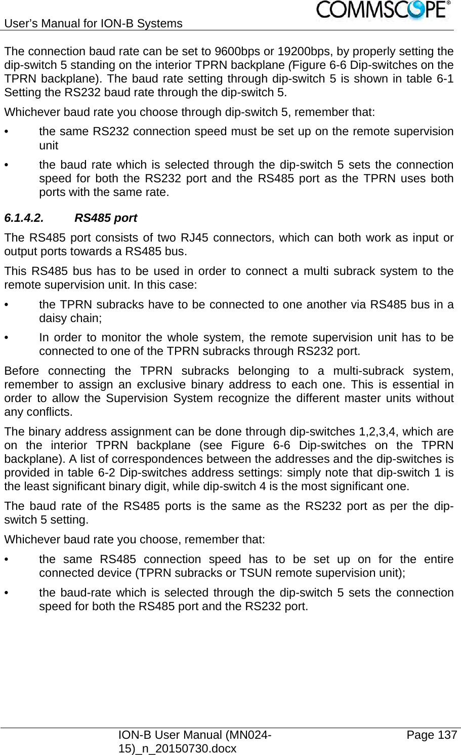
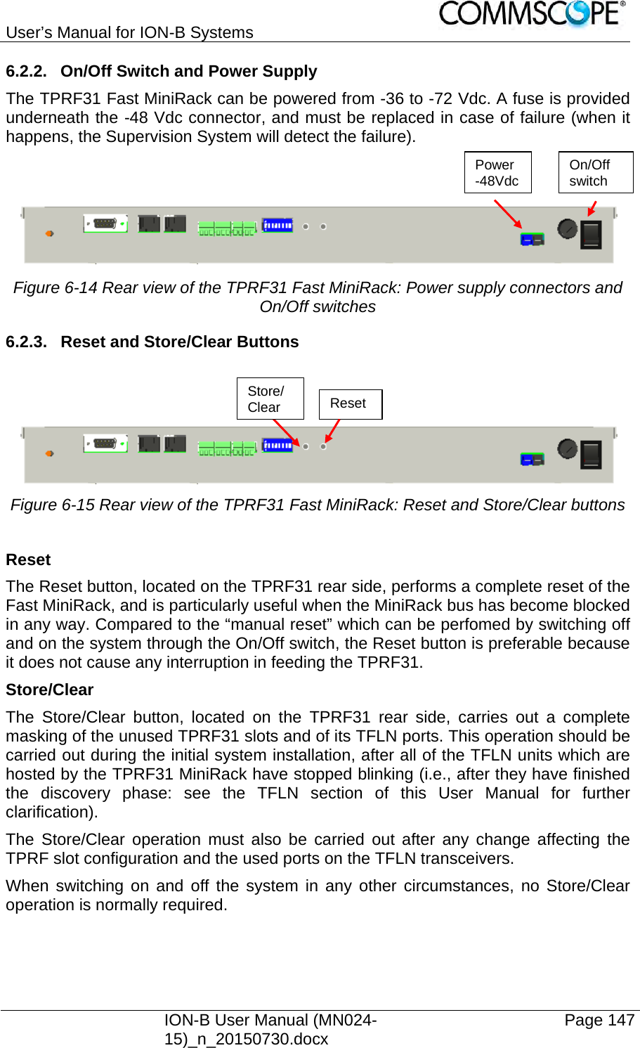
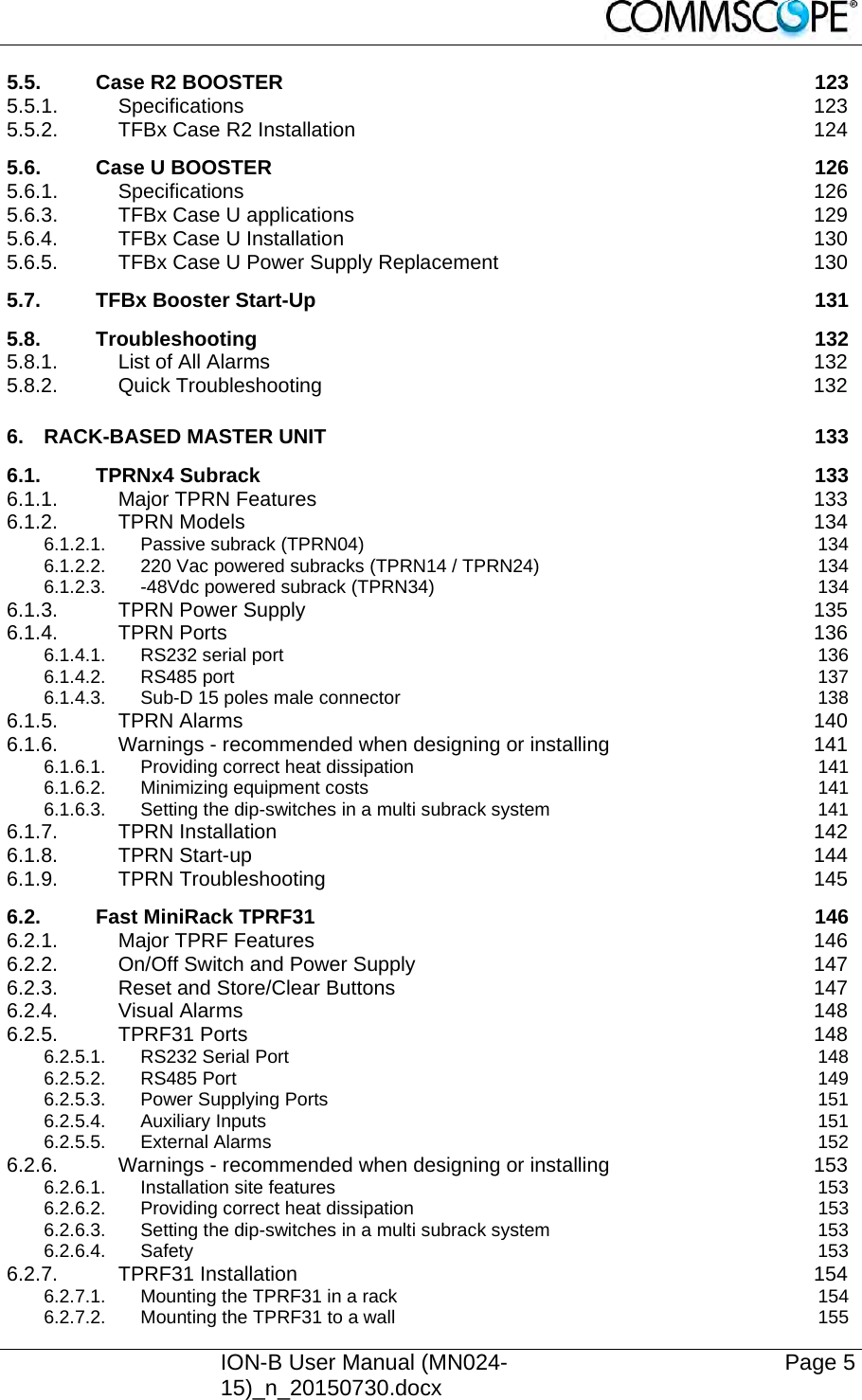
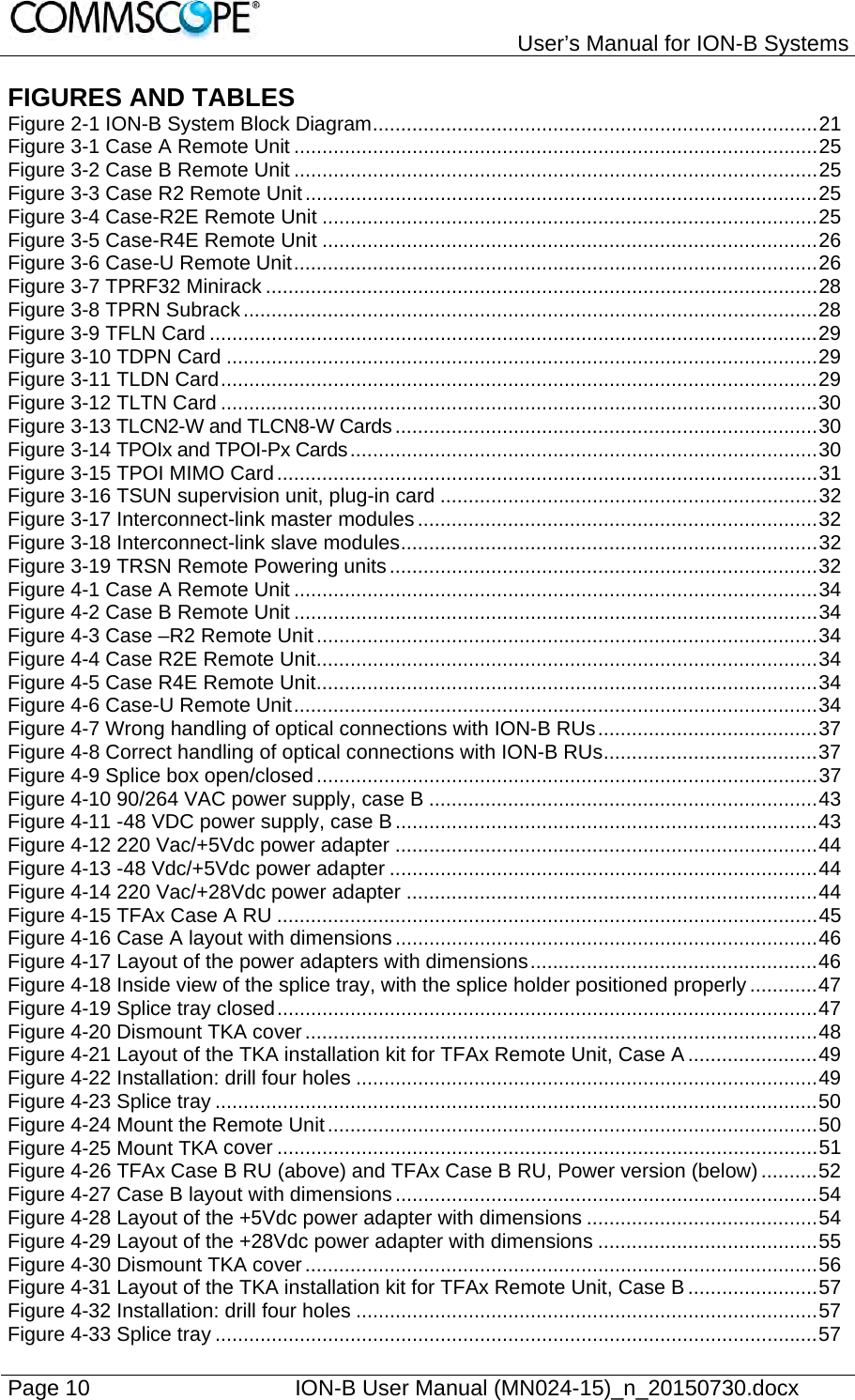
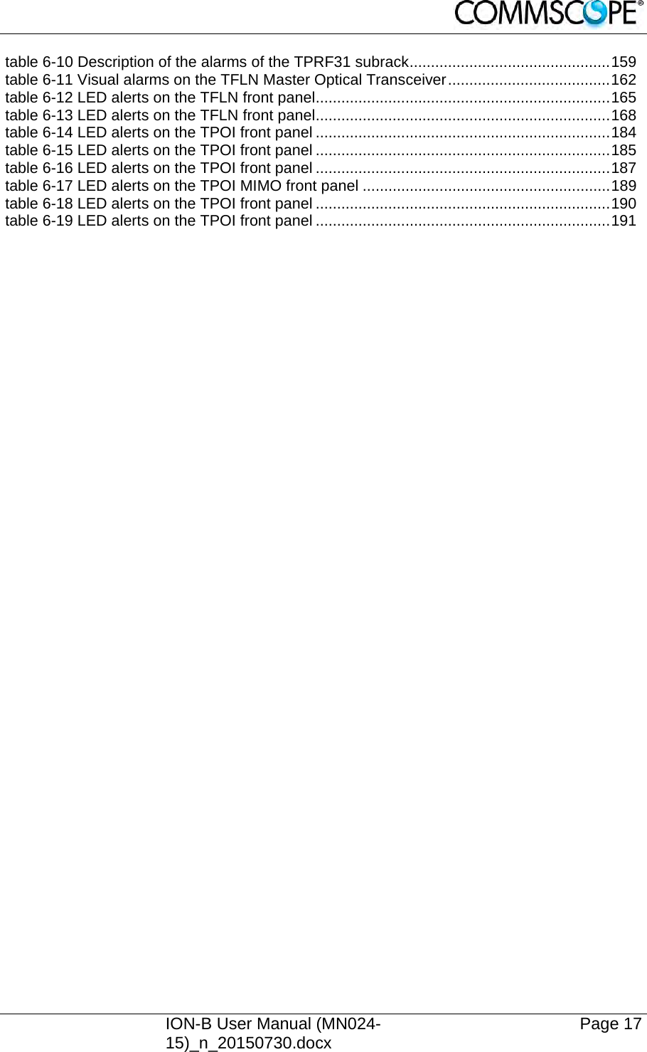
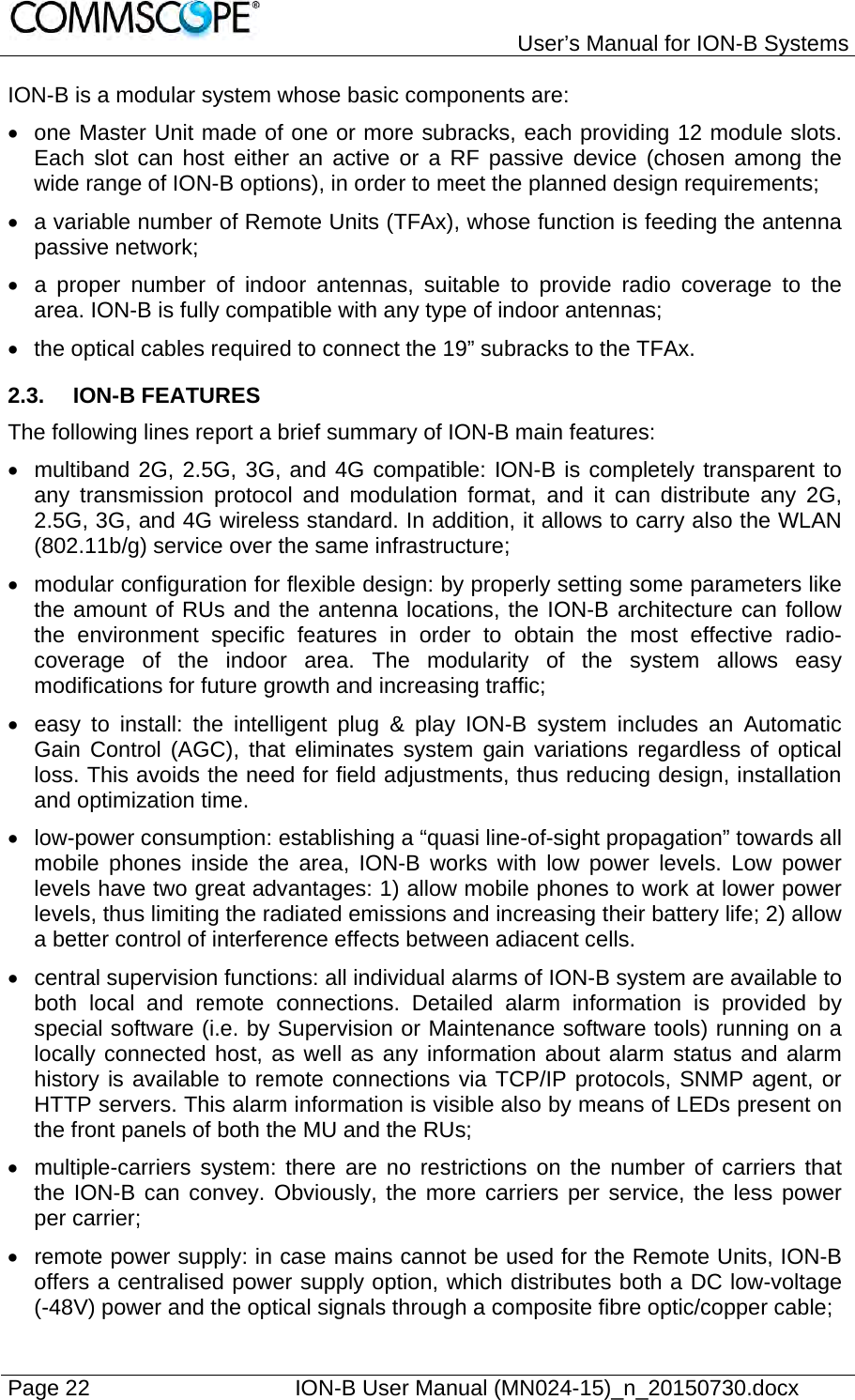
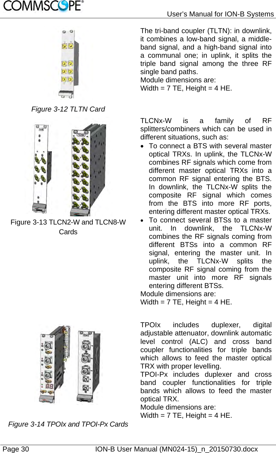
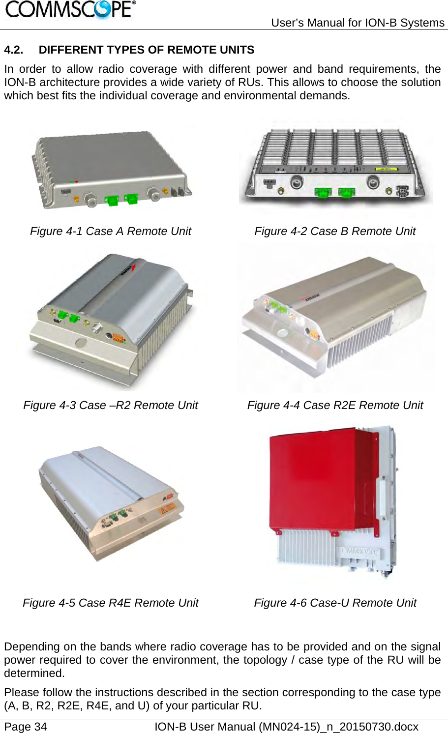
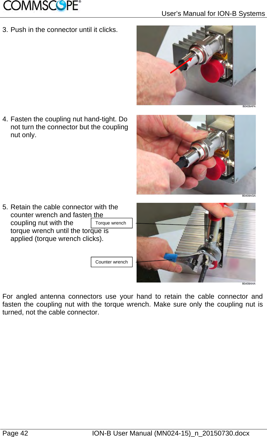
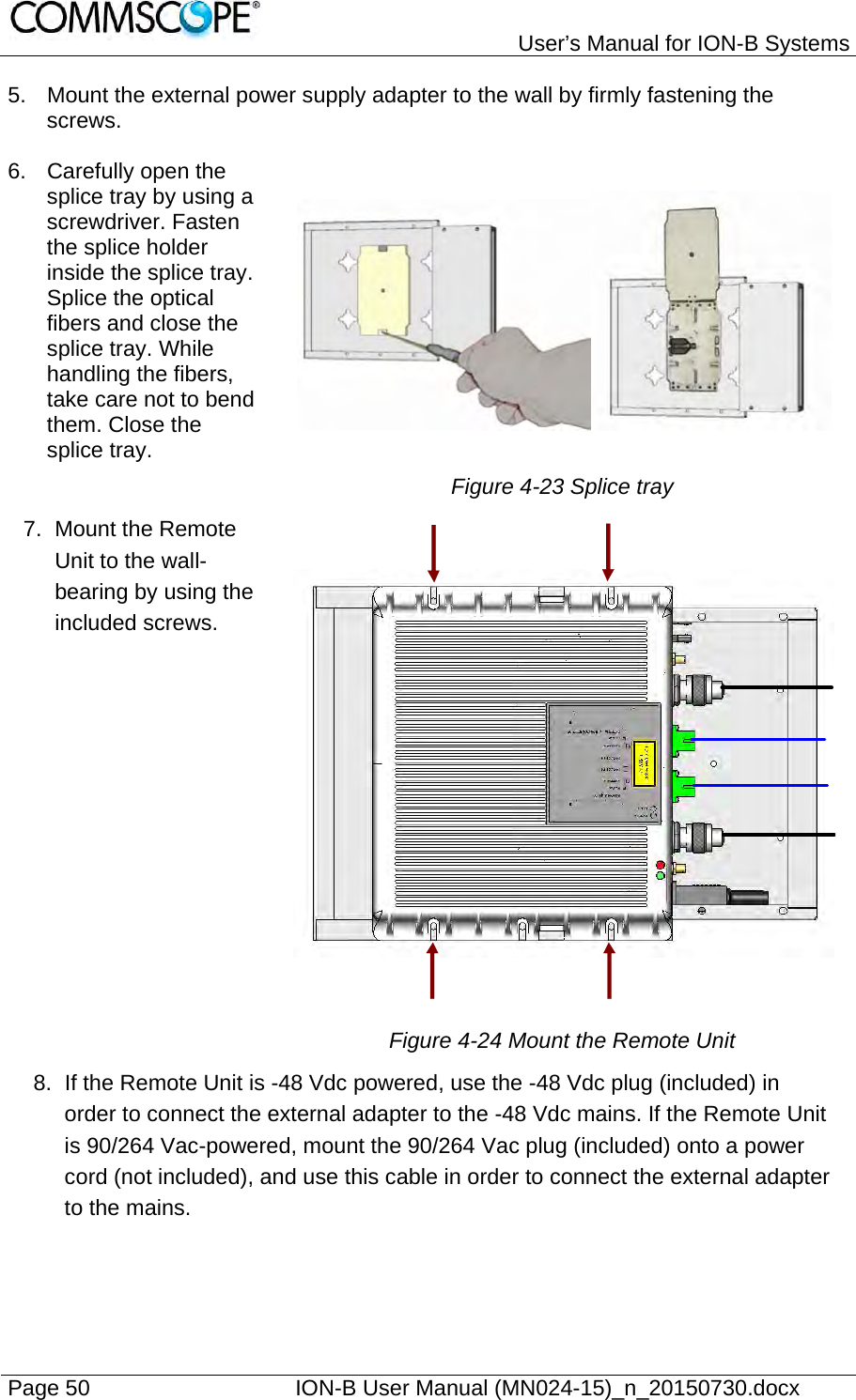
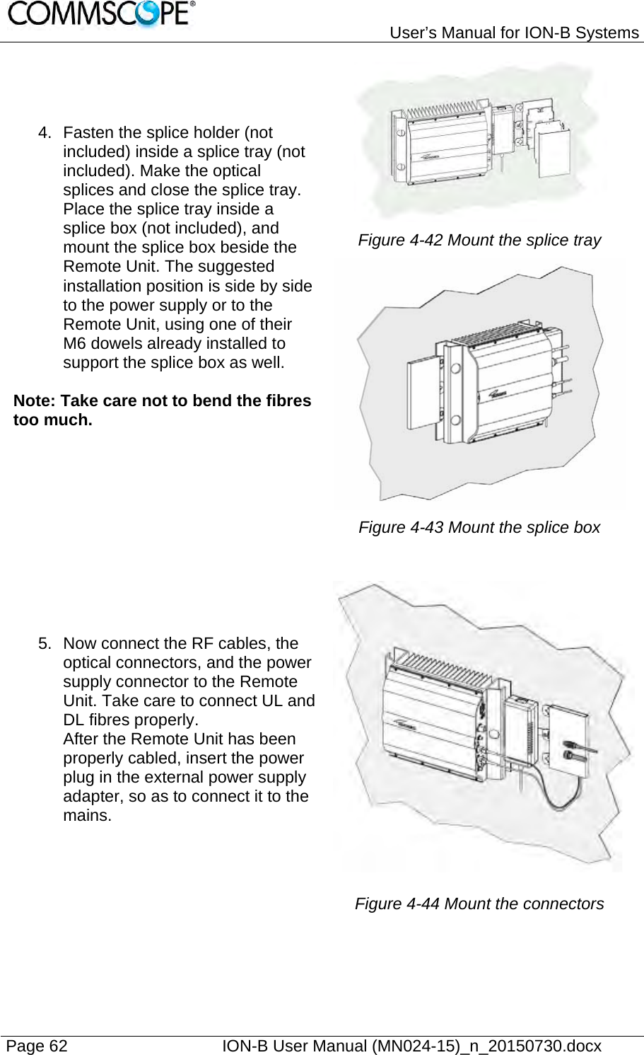
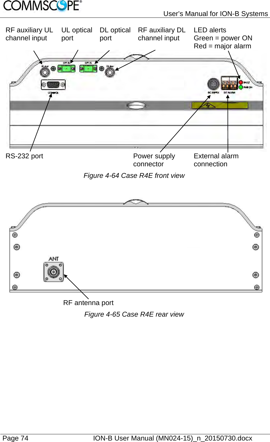
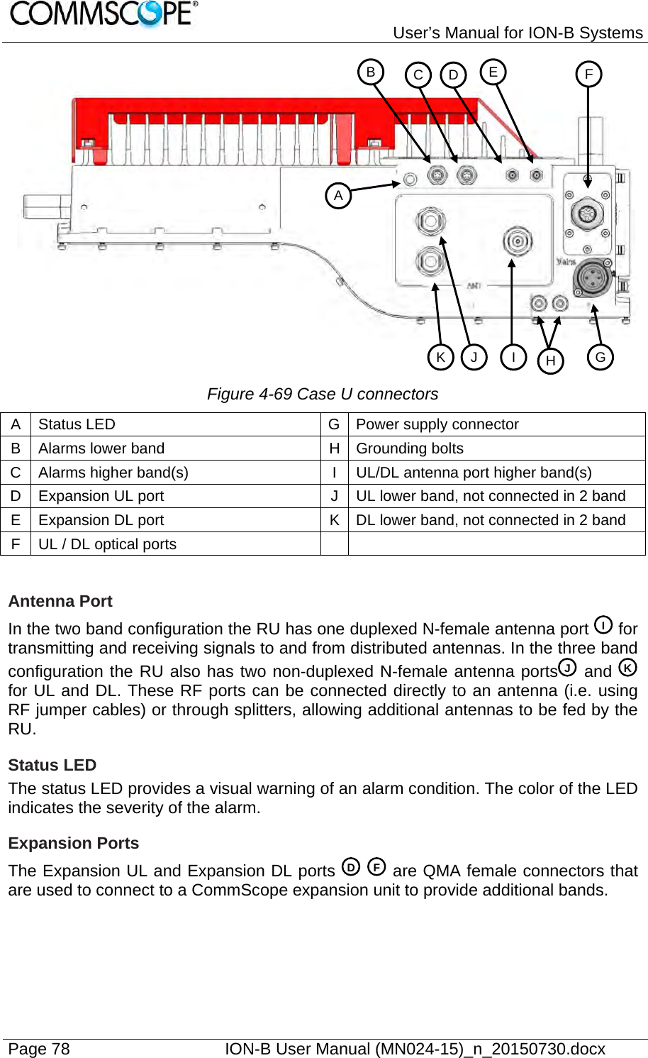
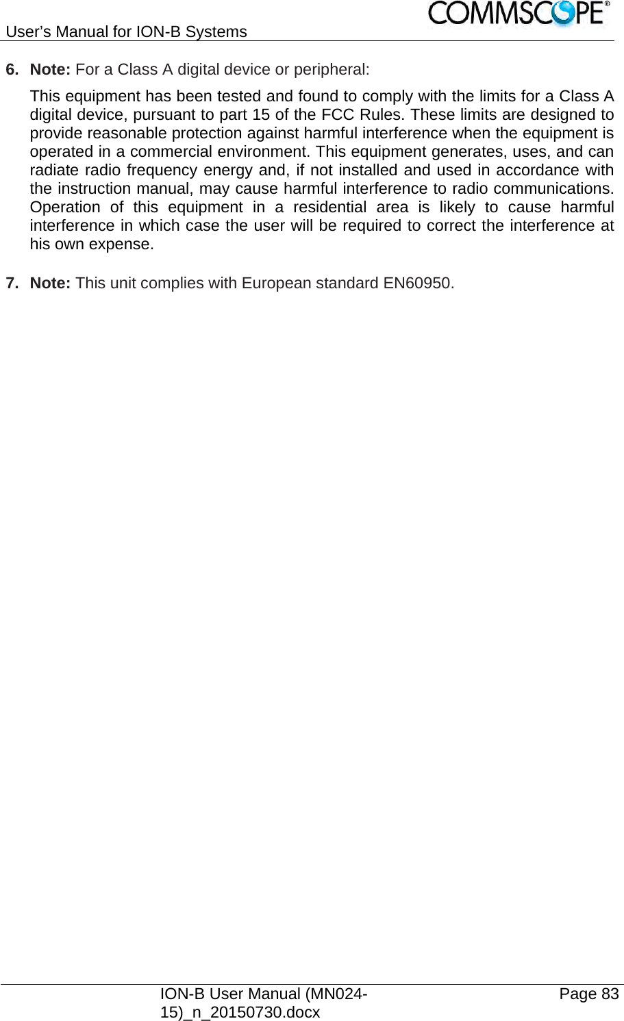
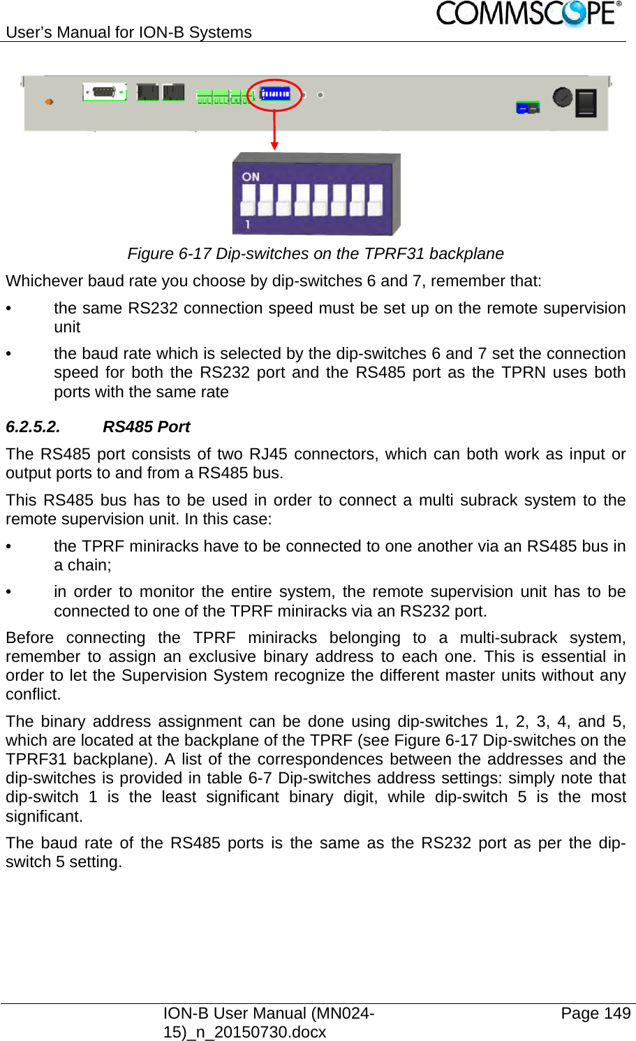
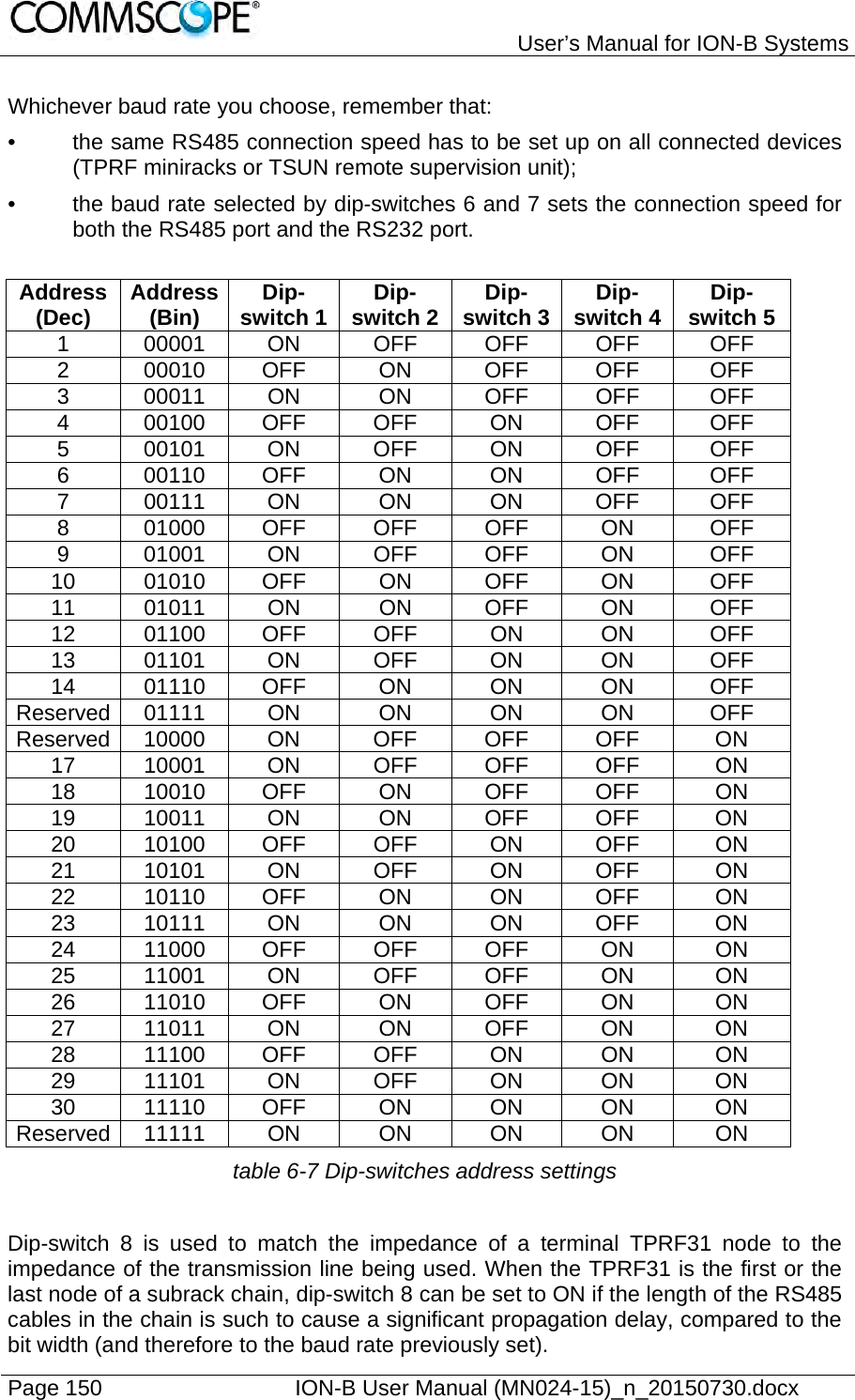
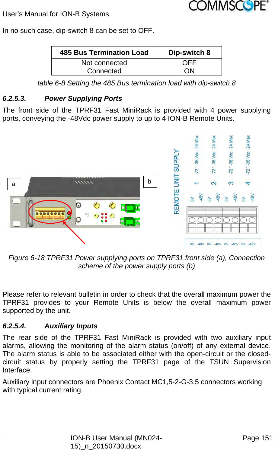
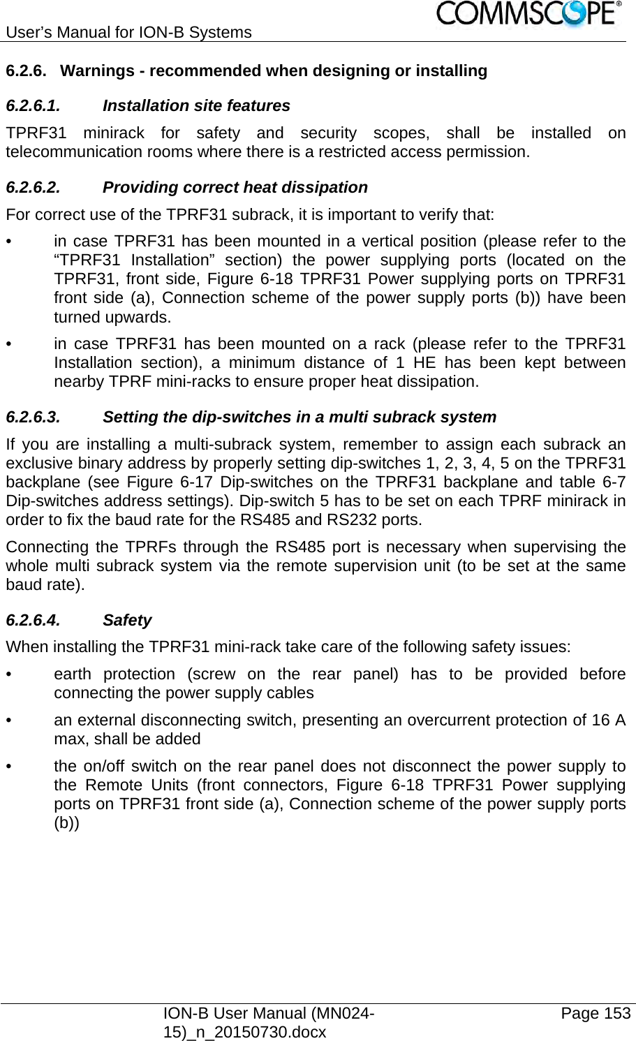
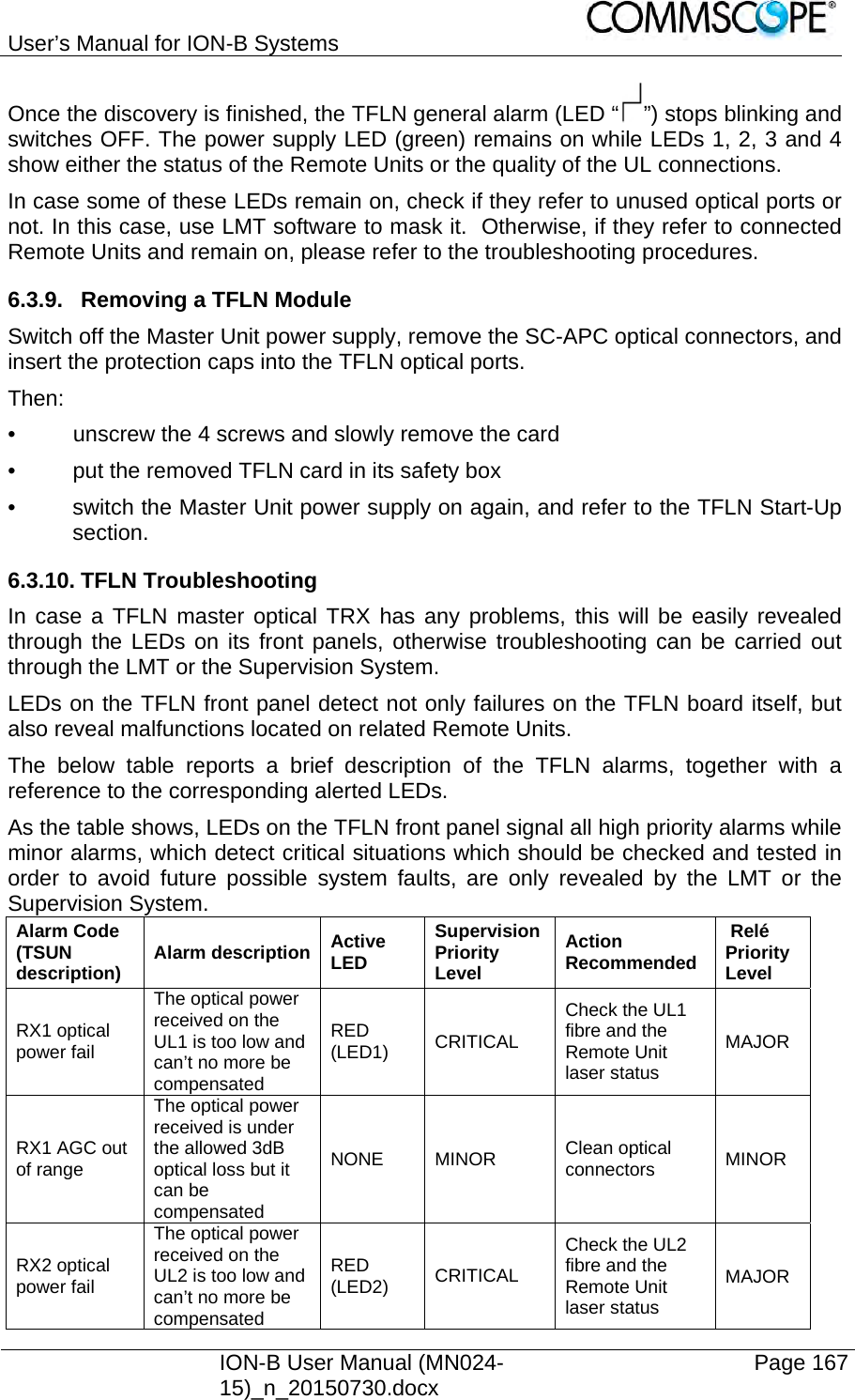
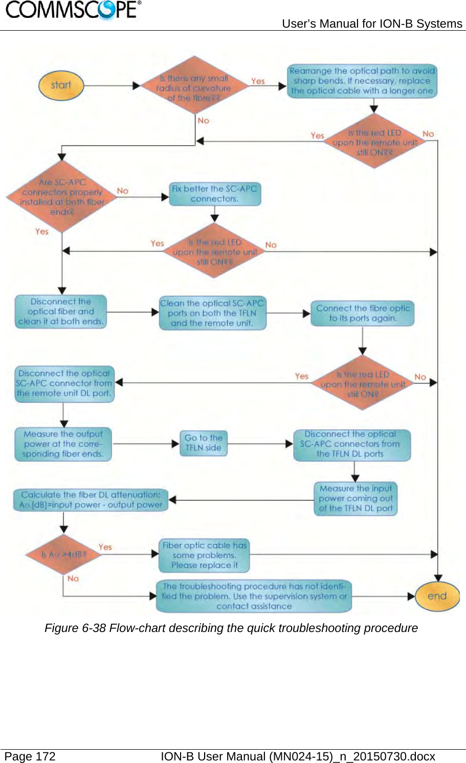
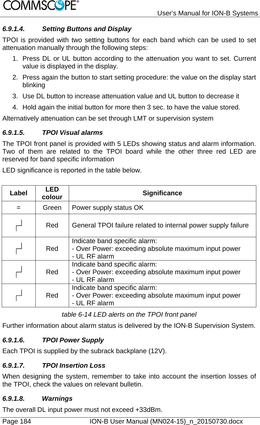
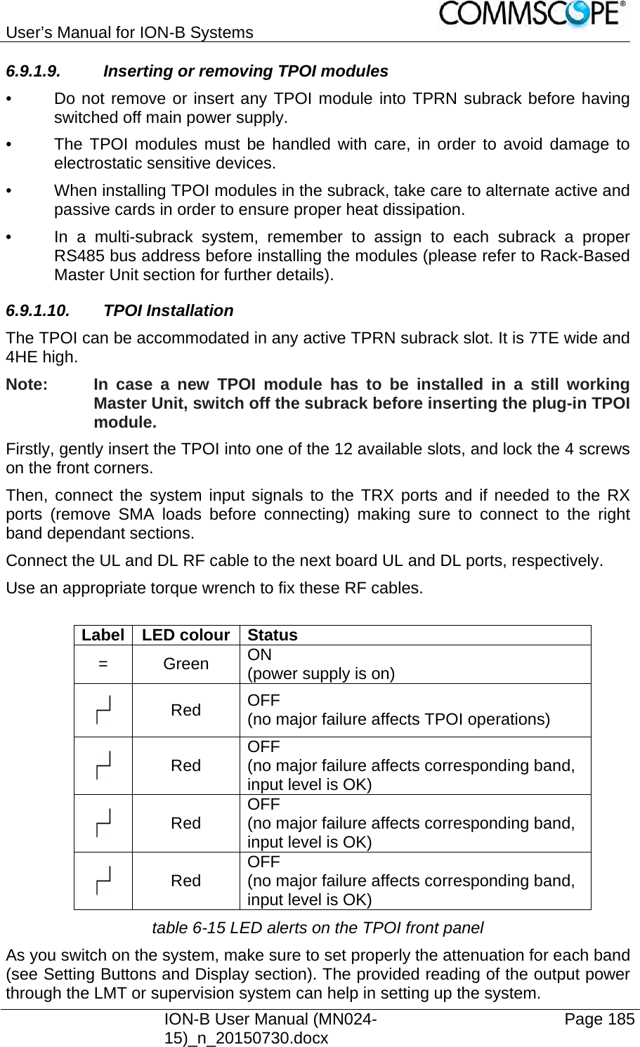
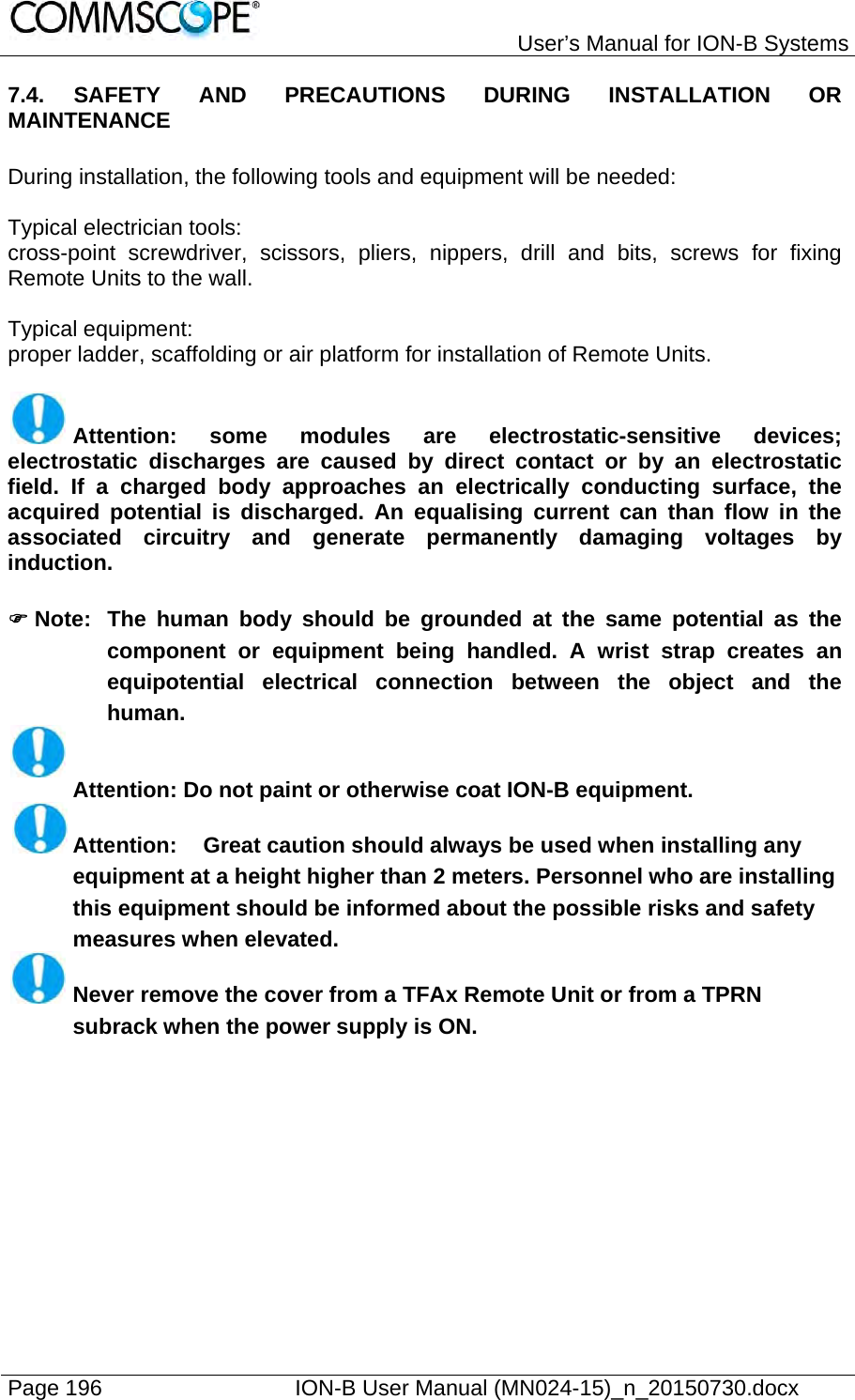
![User’s Manual for ION-B Systems Page 148 ION-B User Manual (MN024-15)_n_20150730.docx 6.2.4. Visual Alarms The TPRF31 front panel is provided with 2 LEDs, showing status and alarm information. LED significances are provided in the following table. LED colour Significance Red Failure on the TPRF31, on one of the TFLN master transceivers, or on one of the connected Remote Units Green Power supply status OK Figure 6-16 TPRF31 visual alarms table 6-5 Meaning of the LEDs on the TPRF31 front-side Further information about alarm status is delivered by the ION-B Supervision Systems. 6.2.5. TPRF31 Ports The TPRF31 is provided with a series of ports which allow for the connection to any external device. These different ports are described hereinafter. 6.2.5.1. RS232 Serial Port The RS232 serial port can be used to connect the TPRF minirack to the remote supervision unit or to a laptop running LMT software. Please note that a standard RS232 cable is needed. The connection baud rate can be set to 9600 bps, 19200 bps, 57600 bps, or 115200 bps by properly setting the dip-switches 6 and 7 on the rear panel of the TPRF31 backplane (Figure 6-17 Dip-switches on the TPRF31 backplane). The baud rate setting using the dip-switches 6 and 7 is shown in table 6-6 Setting the RS232 baud-rate through dip-switches 6 and 7. Baud Rate [bps] Dip-switch 6 Dip-switch 7 9600 OFF OFF19200 ON OFF 57600 OFF ON 115200 ON ON table 6-6 Setting the RS232 baud-rate through dip-switches 6 and 7](https://usermanual.wiki/Andrew-Wireless-System/UEBL2323.user-manual/User-Guide-2794507-Page-148.png)

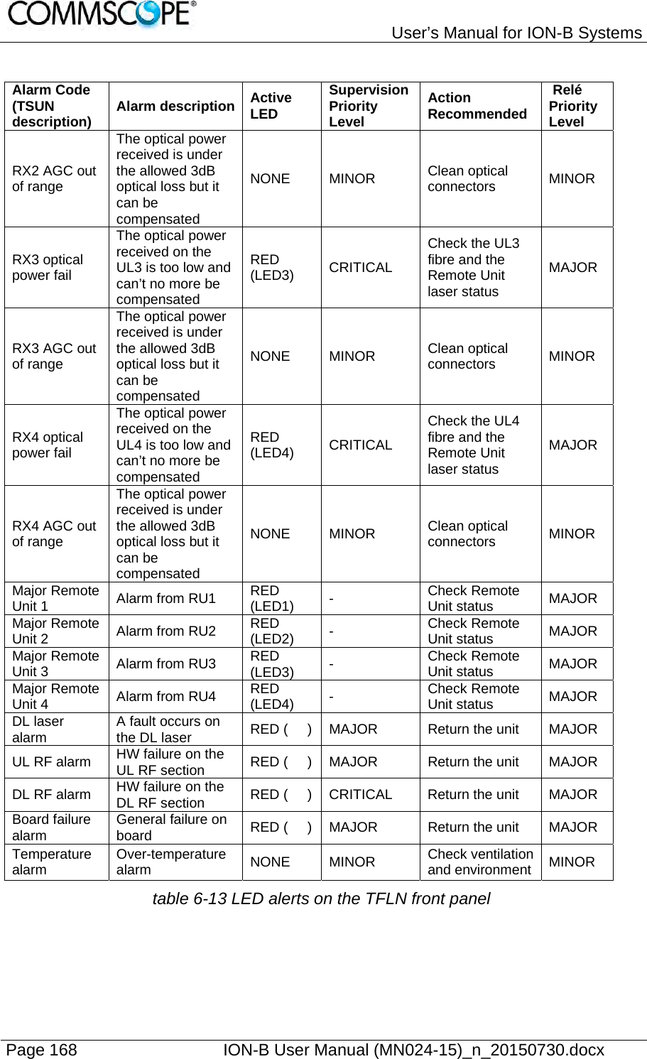
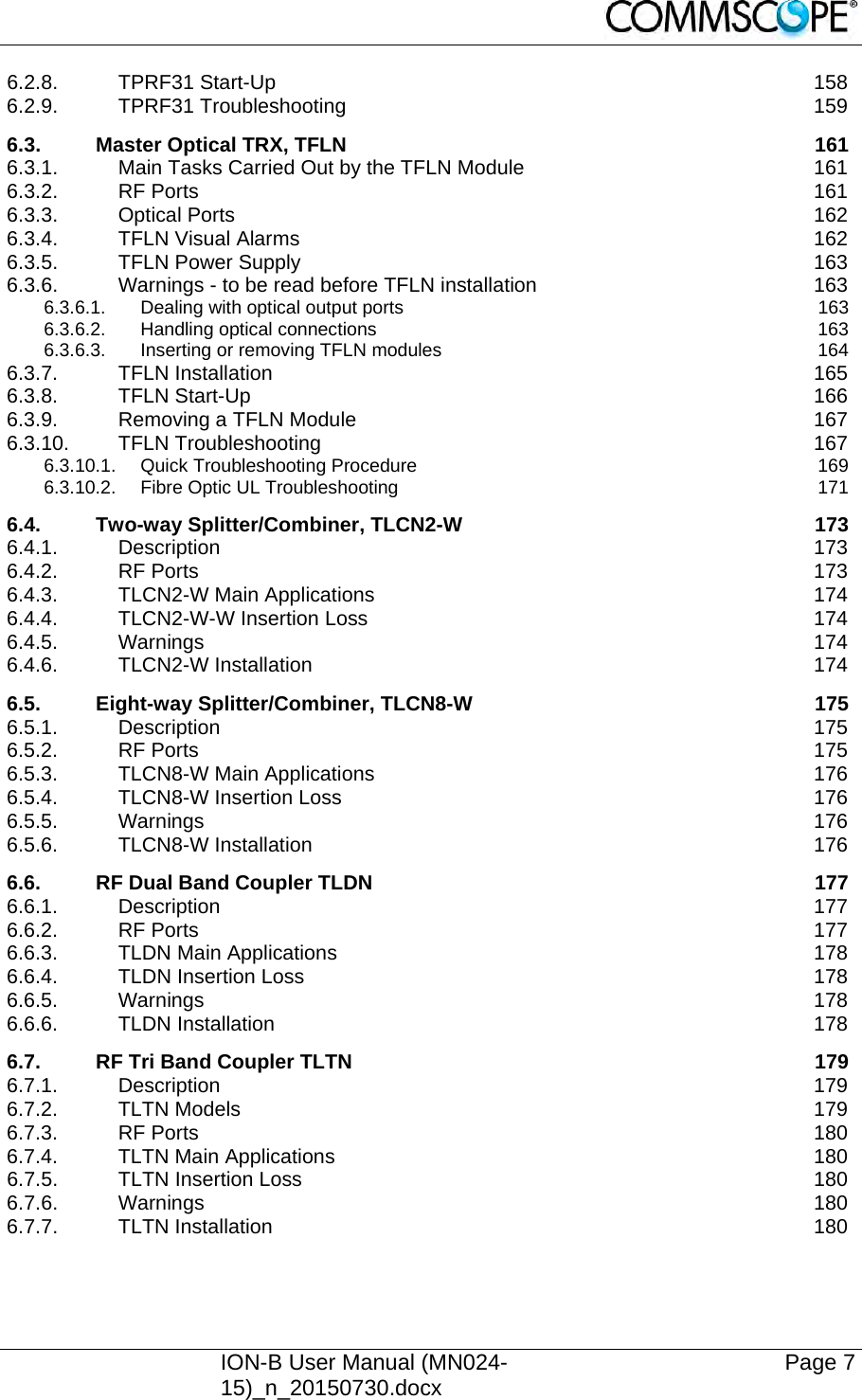
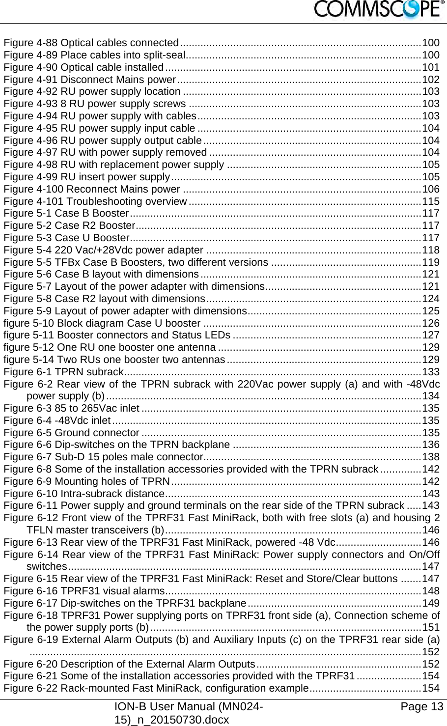
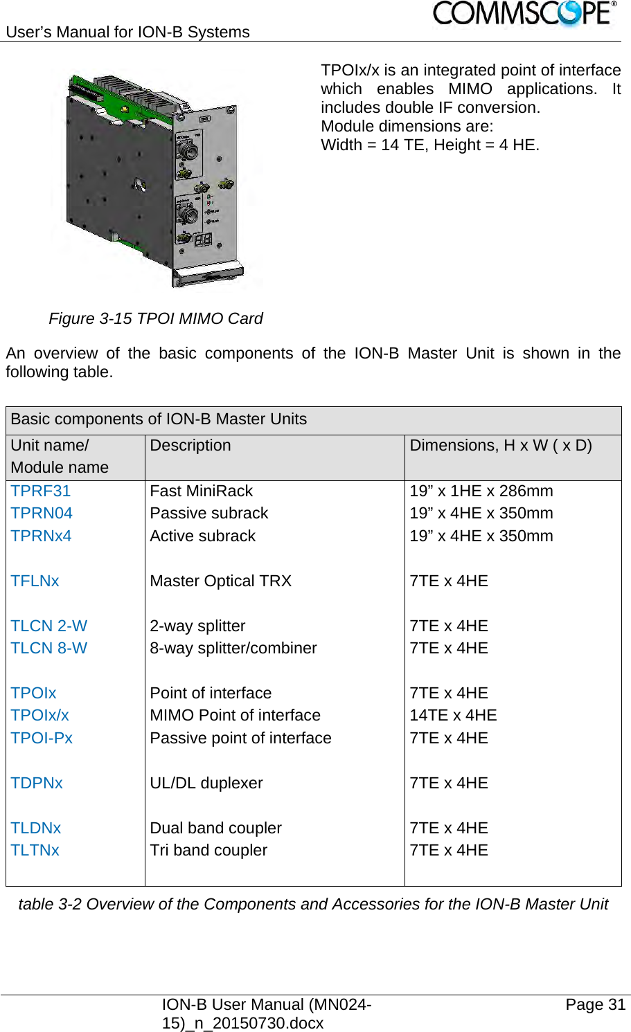
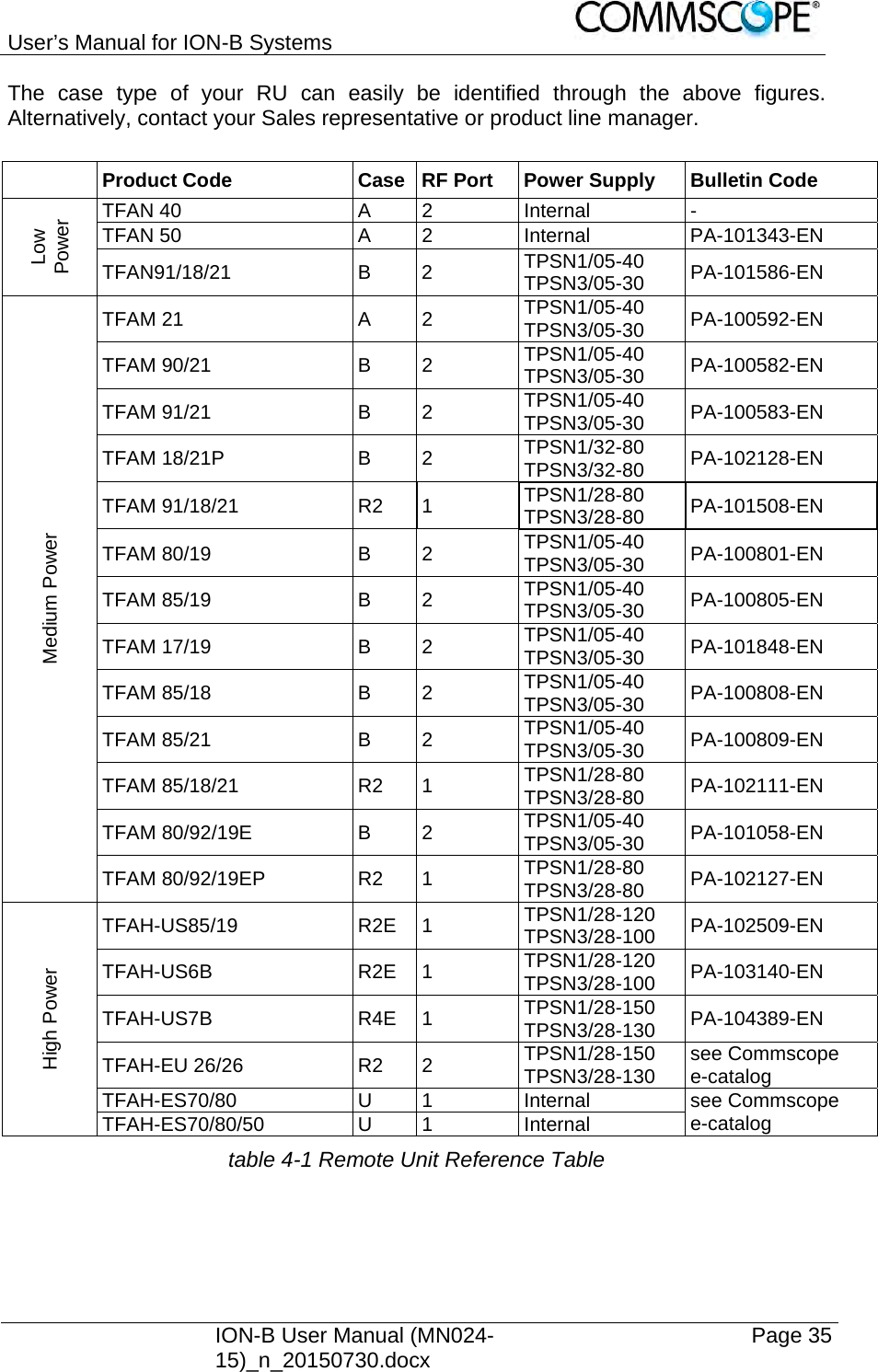
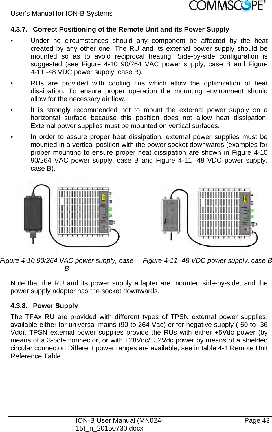
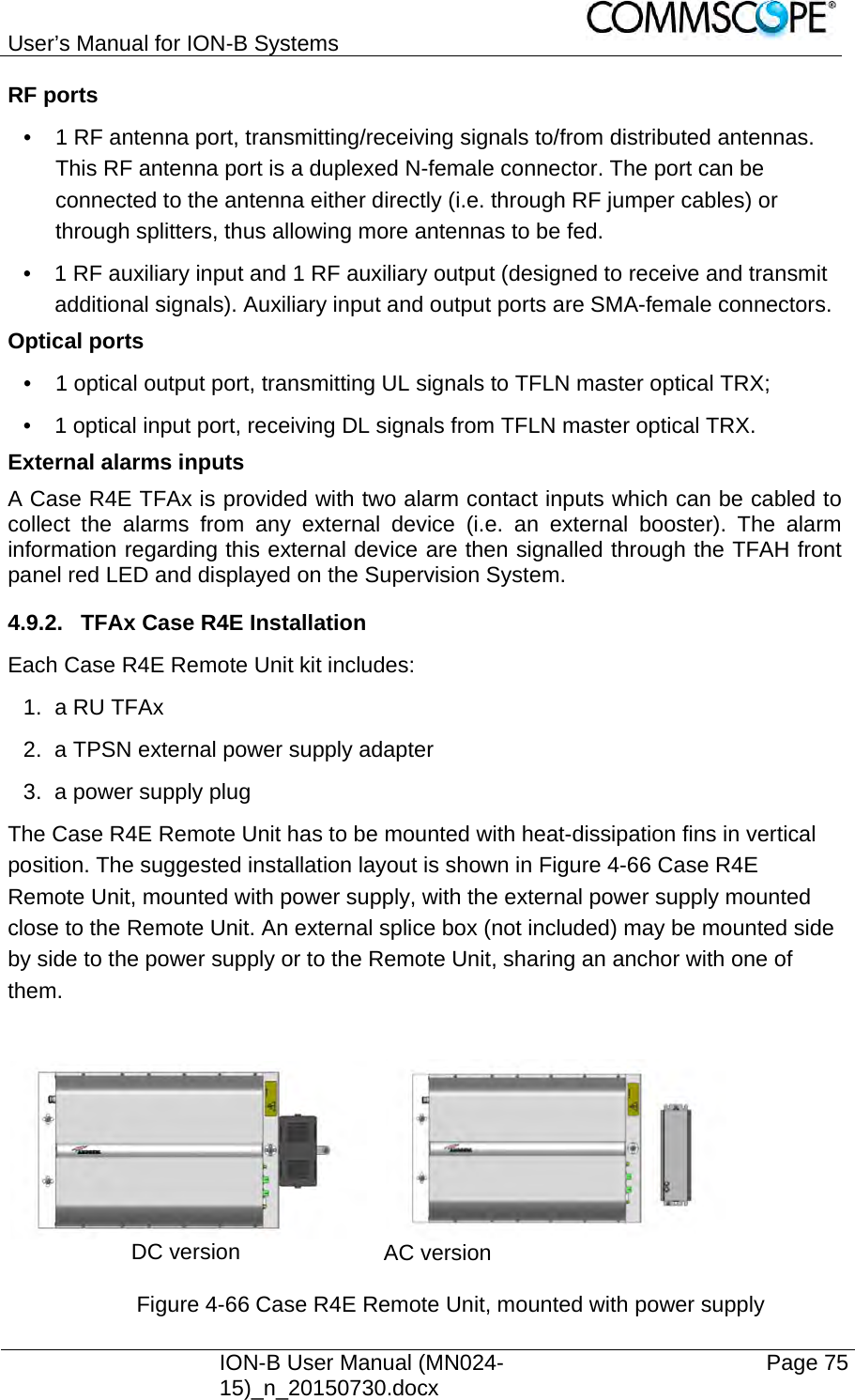
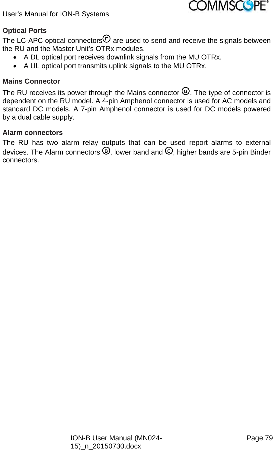
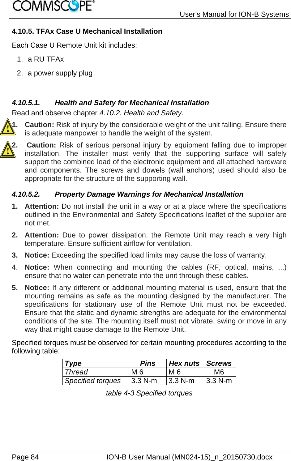
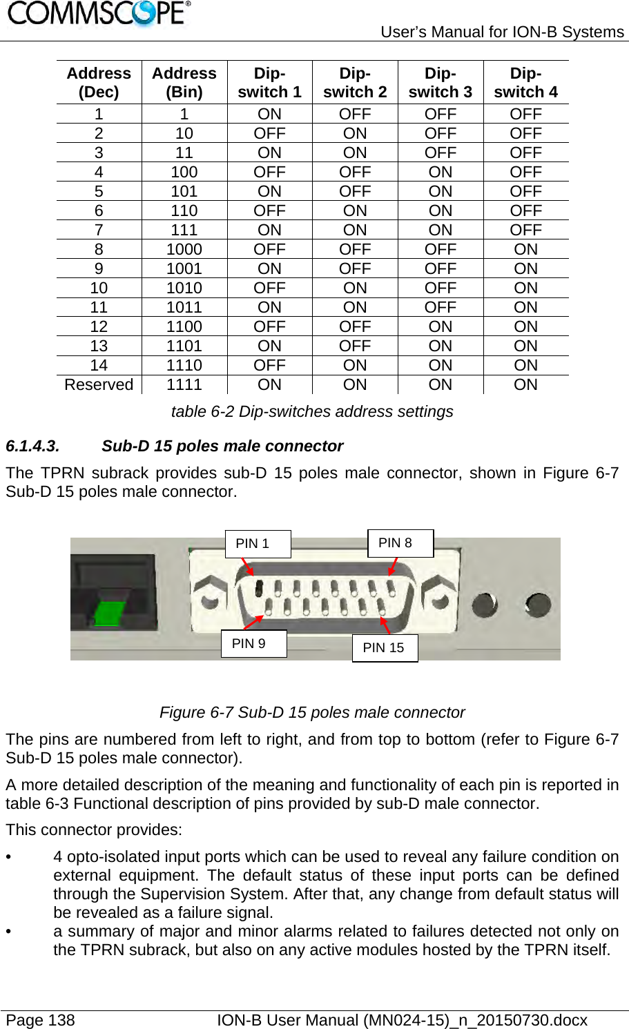
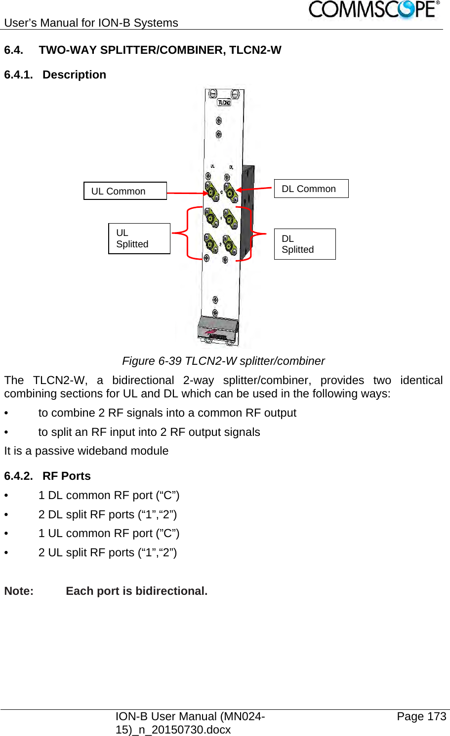
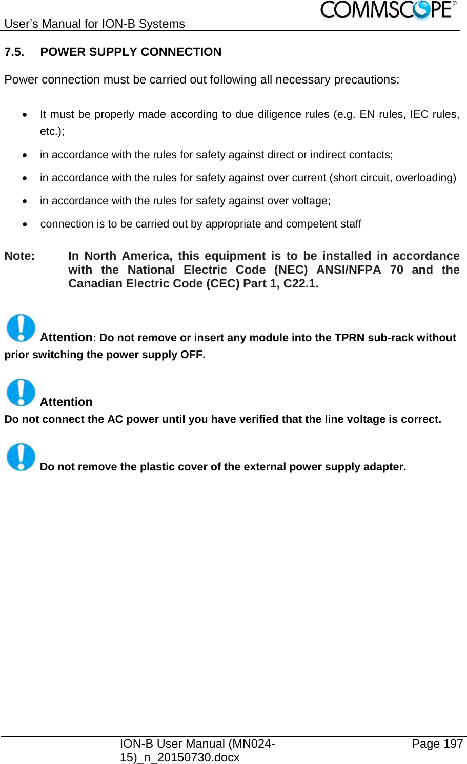
![User’s Manual for ION-B Systems ION-B User Manual (MN024-15)_n_20150730.docx Page 171 6.3.10.2. Fibre Optic UL Troubleshooting The following procedure is summarized by the flow-chart Figure 6-38 Flow-chart describing the quick troubleshooting procedure. 1. Check if there is any point where the fibre experiences a small radius of curvature. In this case, rearrange the optical path in order to avoid sharp bends (if necessary, replace the optical cable with a longer one). If this causes the TFLN red LED to switch off, troubleshooting has been successful. Otherwise, follow this next step. 2. Check if the SC-APC connectors are properly installed at both fibre ends (i.e. TFLN and TFAx ports). If not, fix the SC-SPC connectors better to their relevant adapters. If this causes the TFLN red LED to switch off, troubleshooting has been successful. Otherwise, follow this next step. 3. Disconnect the optical fibre and clean it at both fibre ends (i.e. TFLN side and TFAx side) then reconnect the fibre to relevant ports. In case this causes the TFLN red LED to switch off, troubleshooting has been successful. Otherwise, follow the next step. 4. Disconnect the optical SC-APC connector from TFLN UL port, and measure the output power POUT(UL) at the corresponding fibre end. Then, go to the TFAx side, disconnect the optical SC-APC connector from TFAx UL port and measure the input power PIN(UL) coming out of the TFAx UL port. 5. Calculate the UL fibre attenuation AUL as: AUL [dB] = PIN(UL) – POUT(UL) a. If AUL > 4dB, the fibre optic cable has some problems or the cable path is too long. Replace it. b. If AUL < 4dB, then the TFAx Remote Unit could be faulty. Before replacing it, check the TFAx status on the Supervision System and contact for assistance](https://usermanual.wiki/Andrew-Wireless-System/UEBL2323.user-manual/User-Guide-2794507-Page-171.png)
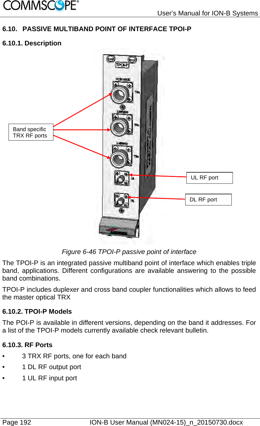
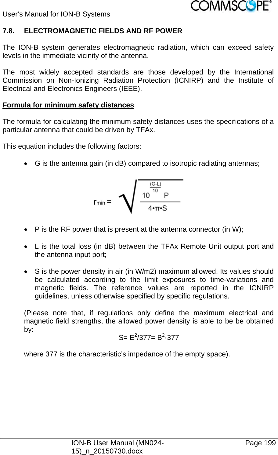
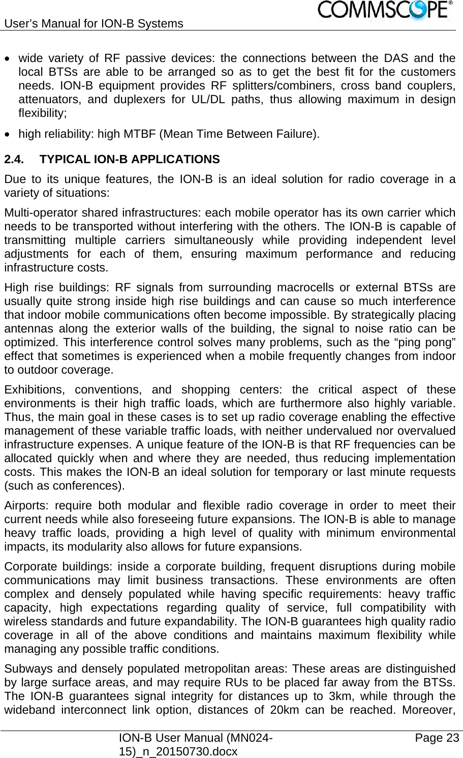
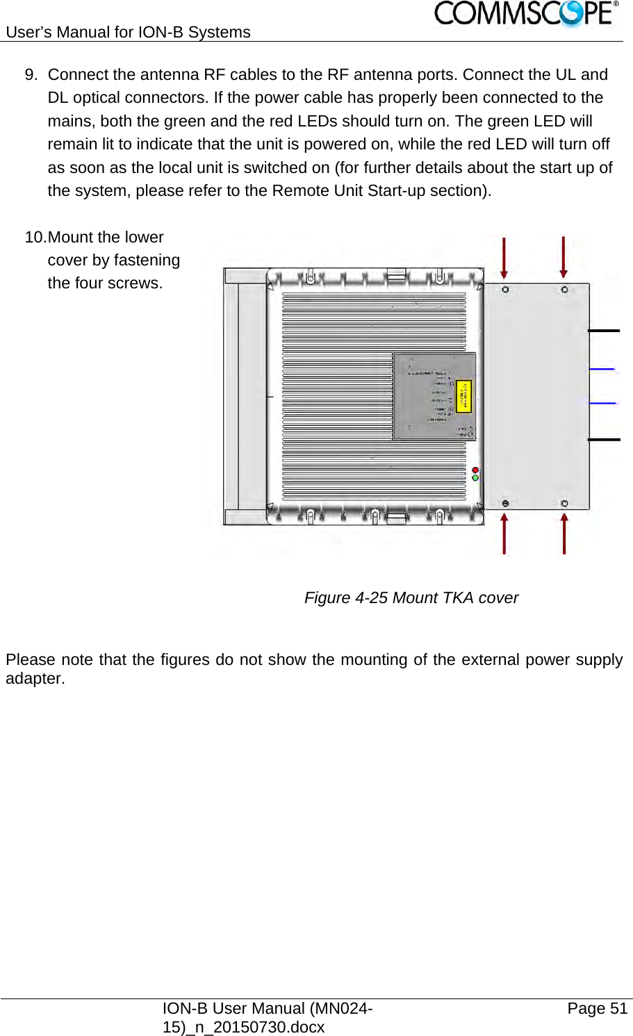
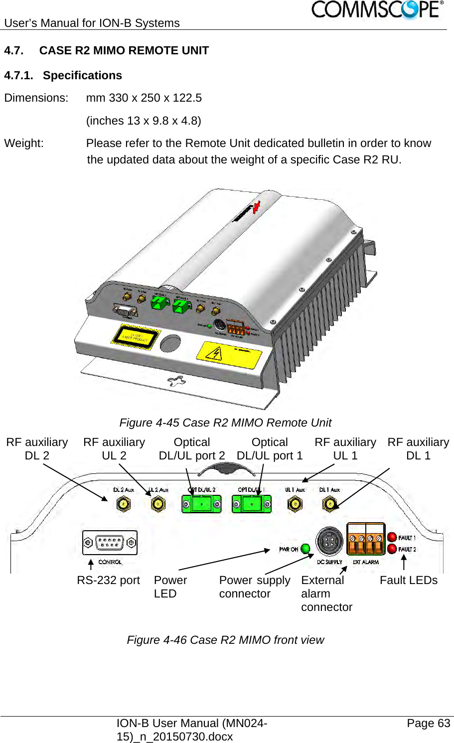
![User’s Manual for ION-B Systems Page 200 ION-B User Manual (MN024-15)_n_20150730.docx Example 1. A Medium Power TFAM 18/20P must distribute mobile signals through a directional antenna, fed by a 2-metre length RG223 cable (no splitters used). The antenna gain is 7 dB and the ION-B system distributes one GSM 1800 MHz carrier and one UMTS 2100 MHz carrier. The maximum allowed power density we have to comply with is: S = 10 W m-2 (typical ICNIRP reference level for general public exposure to time-varied electric and magnetic fields). By reading the relevant notes for the TFAM 18/20P Remote Unit, we know the overall output power at the antenna port is able to be estimated as follows: 20 dBm ± 2 ( +22 dBm maximum, equivalent to 0.158 W) for the Cellular 850 MHz band 20 dBm ± 1.5 ( +21.5 dBm maximum, equivalent to 0.141 W) in the PCS 1900 MHz band. The total output power at the antenna port is therefore P = 0.158 + 0.141 = 0.299 W. By reading the cable specs, we get that RG223 cable losses can be estimated at 0.55 dB/m. Total losses between the TFAM 18/20P output port and the antenna input port can therefore be estimated as follows: L = 0.55 (dB/m) x 2 (m) = 1.1 dB By replacing the above values of G, L, P, S parameters inside the formula 6.1, we therefore get the the following minimum safety distance from the antenna: rmin = { 10 -· exp [ (7 - 1.1) / 10 ] · 0.299} / (4·π·10) } - exp (1/2) = 0.096 m Example 2: A Low Power TFAH85/19 through a directional antenna is used, fed by a 20 -metre length ½” cable, with a 2-way splitter. The antenna Gain is 7 dB and the ION-B system distributes one Cellular 850 MHz carrier and one PCS 1900 MHz carrier. The maximum allowed power density we have to comply with is: S = 50 W·m2 (typical ICNIRP reference level for occupational exposure to time-varied electric and magnetic fields)](https://usermanual.wiki/Andrew-Wireless-System/UEBL2323.user-manual/User-Guide-2794507-Page-200.png)
![User’s Manual for ION-B Systems ION-B User Manual (MN024-15)_n_20150730.docx Page 201 By reading the ION-B notes, we know that the output power per carrier at the TFAM antenna port is 30 dBm ± 2 ( +32 dBm maximum, equivalent to 1.202 W) for the Cellular 850 MHz band 30 dBm ± 2 ( +32 dBm maximum, equivalent to 1.202 W) for the PCS 1900 MHz band The ½” cable losses are 0.07 dB/ m in the 900 MHz band, and 0.11 dB/m in the 2100 MHz band. The splitter insertion losses are 3.5 dB. The total losses between the TFAH85/19 output port and the antenna input ports can therefore be estimated as follows: L850MHz = 0.07 (dB/m) x 20 (m) + 3.5 = 4.9 dB for Cellular 850 MHz signals L1900MHz = 0.10 (dB/m) x 20 (m) + 3.5 = 5.5 dB for PCS 1900 MHz signals The term “10 exp (G-L/10) P” which appears inside the formula 6.1 should therefore be calculated seperately for each frequency, and then added in order to calculate the composite contribution: P850MHz, ant = 10 exp [(7-4.9)/10]· 1.202 = 1.949 W P1900MHz, ant = 10 exp [(7-5.5)/10]· 1.202 = 1.698 W Pcomposite= P850MHz, ant + P1900MHz,ant = 3.647 W By dividing the total power through (4··S) and taking the square root according to the formula 6.1, we therefore get the following minimum safety distances from the antenna: rmin = { Pcomposite /(4·π·50)} - exp (1/2) = 0.02 m Example 3. There is a Medium Power TFAM91/18/20 which is connected to an omnidirectional antenna through a 10-metre length RG223 cable (no splitters used). The antenna Gain is 7 dB and the ION-B system distributes two GSM900 carriers, two GSM1800carriers, and one UMTS2100 carrier. The maximum allowed electrical field strength is: E = 6 V m (typical Italian reference level for exposure to time-varied electric and magnetic fields). The corresponding value of the maximum allowed power density is: S = E2 /377 = 0.1 W/m2](https://usermanual.wiki/Andrew-Wireless-System/UEBL2323.user-manual/User-Guide-2794507-Page-201.png)
![User’s Manual for ION-B Systems Page 202 ION-B User Manual (MN024-15)_n_20150730.docx By reading the relevant notes for the TFAM 91/18/20 Remote Unit, the overall output power at the TFAM antenna port can be estimated as follows: 20 dBm ± 2 (+22 dBm maximum, equivalent to 0.158 W) for the Cellular 910 MHz: 21 dBm ± 2 ( +23 dBm maximum, equivalent to 0.200 W) for the GSM1800) 26 dBm ± 1 ( +27 dBm maximum, equivalent to 0.501 W) in the UMTS band The total output power at the antenna port is therefore: P = 0.158W x 2 + 0.200W + 0.501W = 1.345 W, By reading the cable specs, we get that RG223 cable losses can be estimated at 0.55 dB/m. Total losses between the TFAM 91/18/20 output port and the antenna input port can therefore be estimated as follows: L = 0.55 (dB/m) x 10 (m) = 5.5 dB By replacing the above values of G, L, P, S parameters inside the formula 6.1, we therefore get the the following minimum safety distance from the antenna: rmin = { 10 - exp [ (7 - 5.5) / 10 ] - 1.345} / (4··0.1) } - exp (1/2) = 1.22 m 7.9. WARNING LABELS CLASS 1 laser product GROUND - Use this terminal for a safety ground connection for the equipment.](https://usermanual.wiki/Andrew-Wireless-System/UEBL2323.user-manual/User-Guide-2794507-Page-202.png)