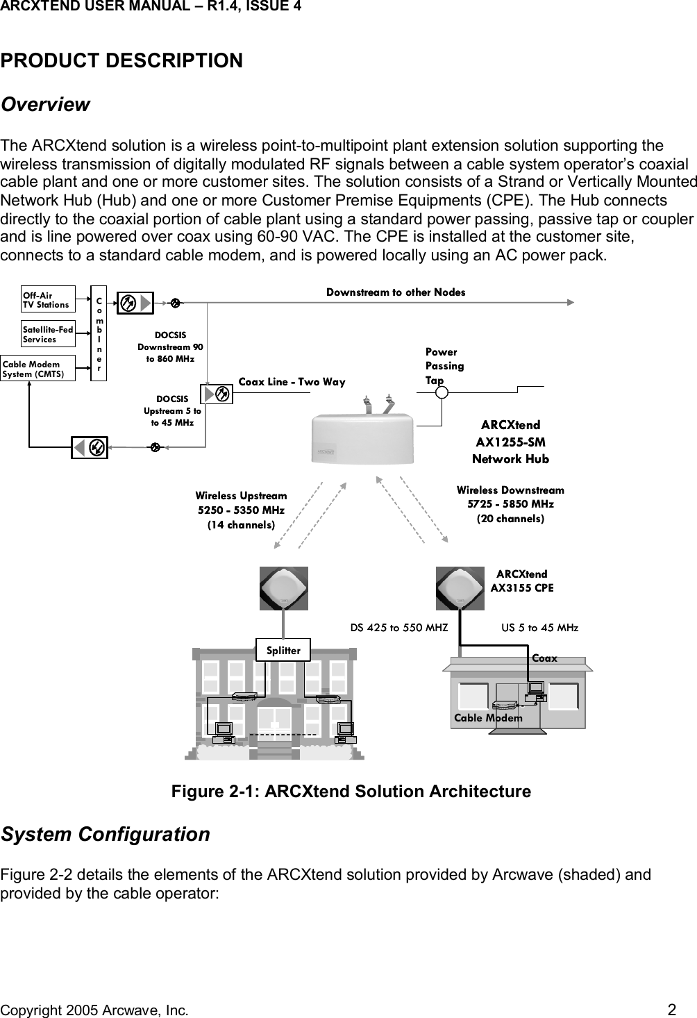
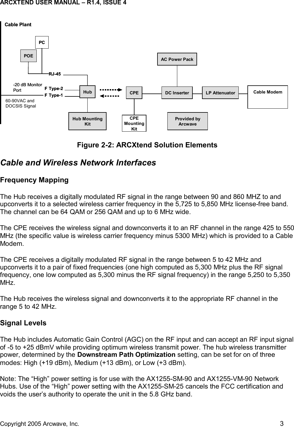
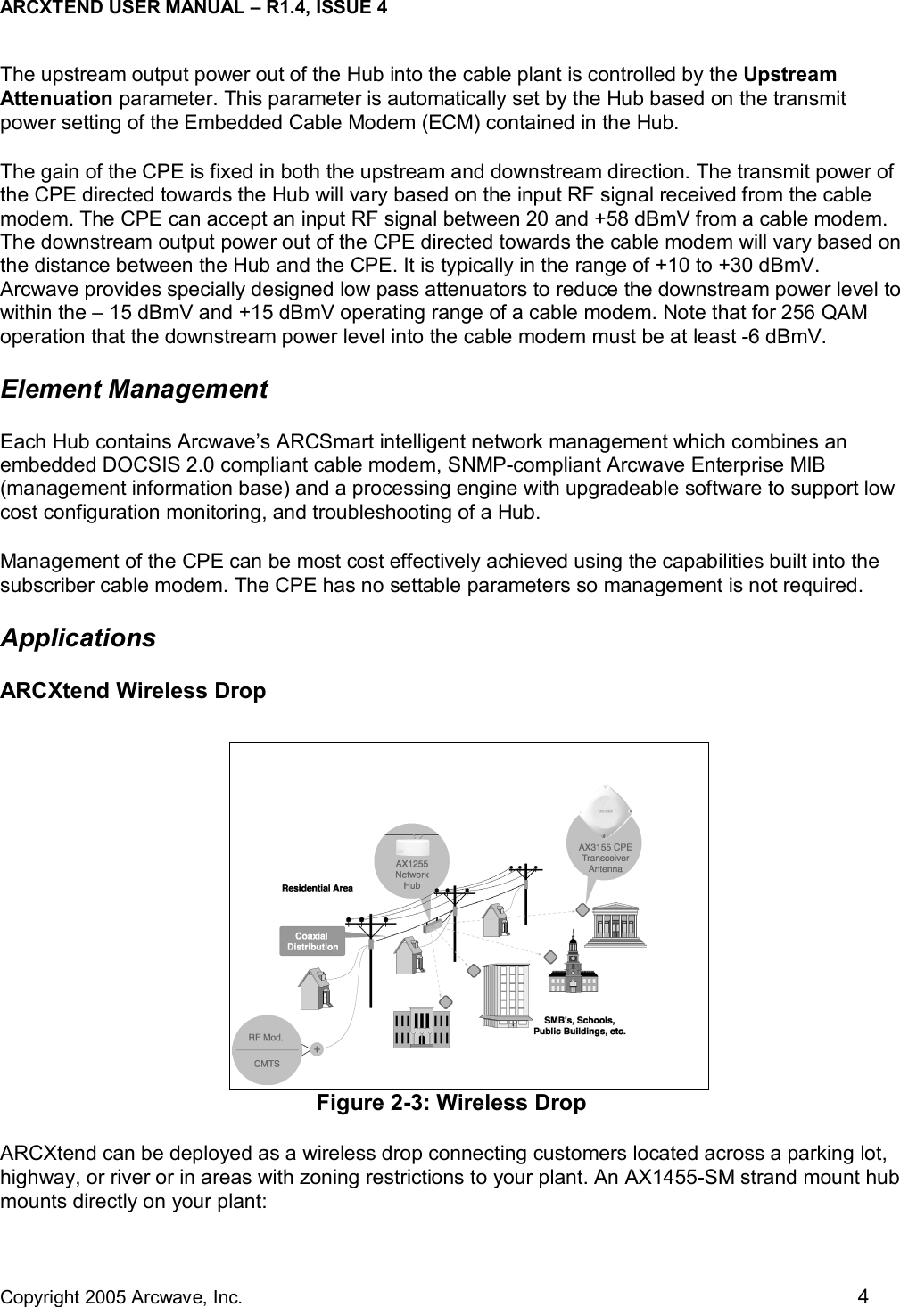
Arcwave AX1255 ArcXTEND Wireless Hub Access Point User Manual 41FF9EC4 410D 10B8EE
Arcwave, Inc. ArcXTEND Wireless Hub Access Point 41FF9EC4 410D 10B8EE
UserManual.wiki
>
Arcwave
>
AX1255 User Manual
Users Manual
Navigation menu
Upload a User Manual
Namespaces
Wiki Guide
HTML
PDF
Info
Views
User Manual
Discussion / Help
Navigation
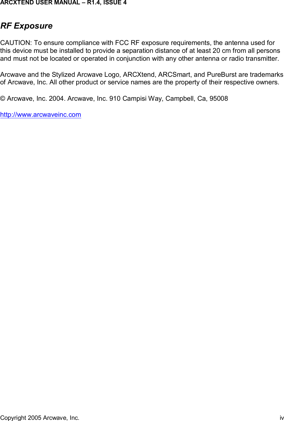
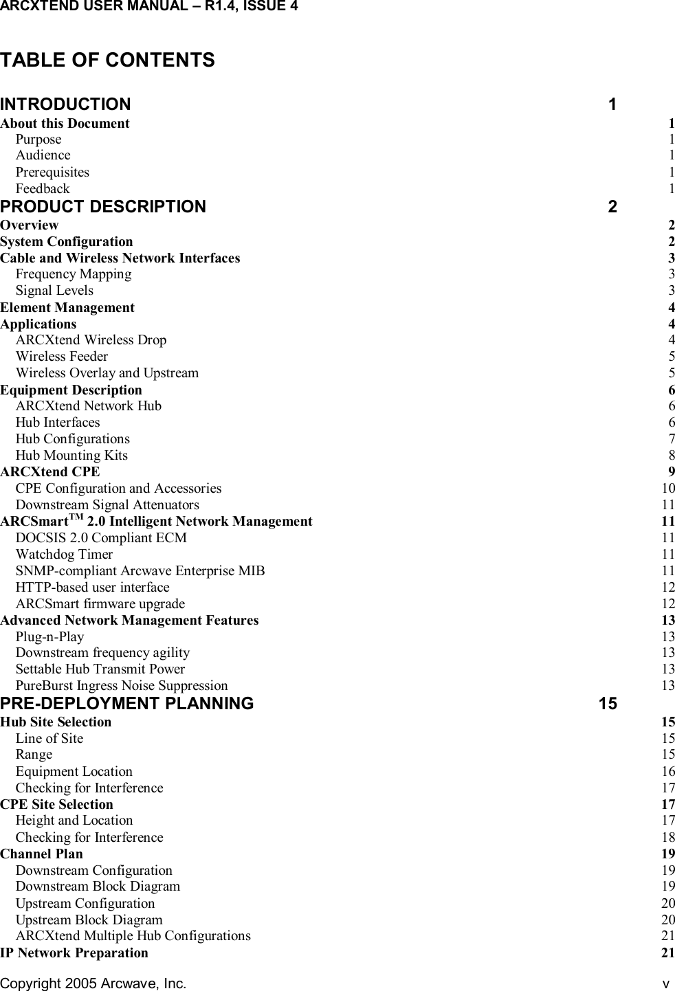
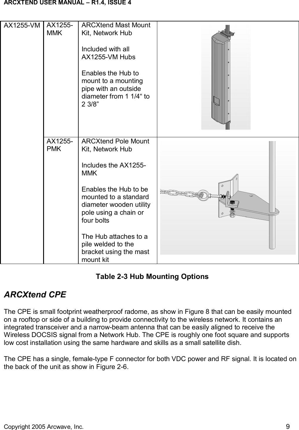
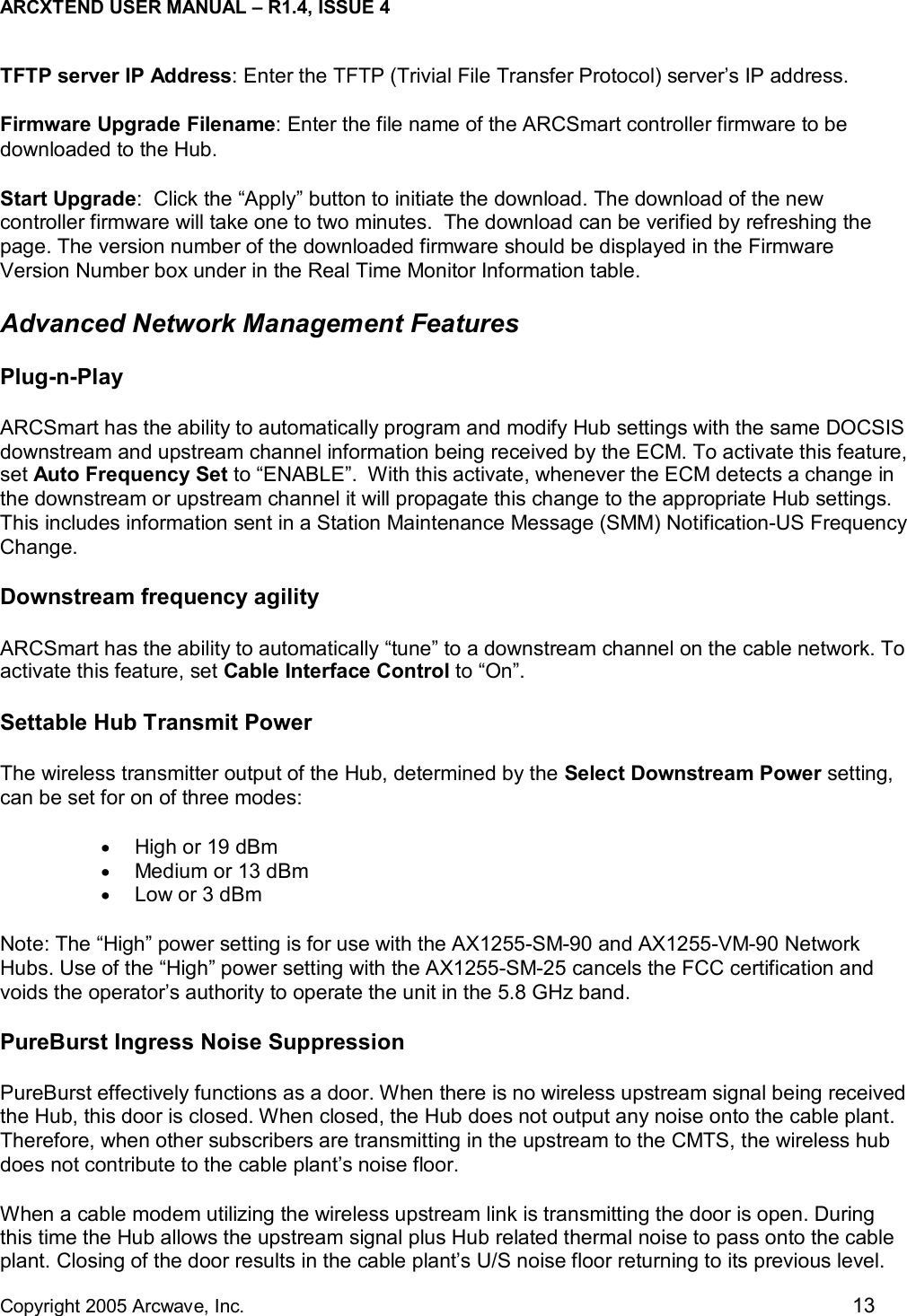
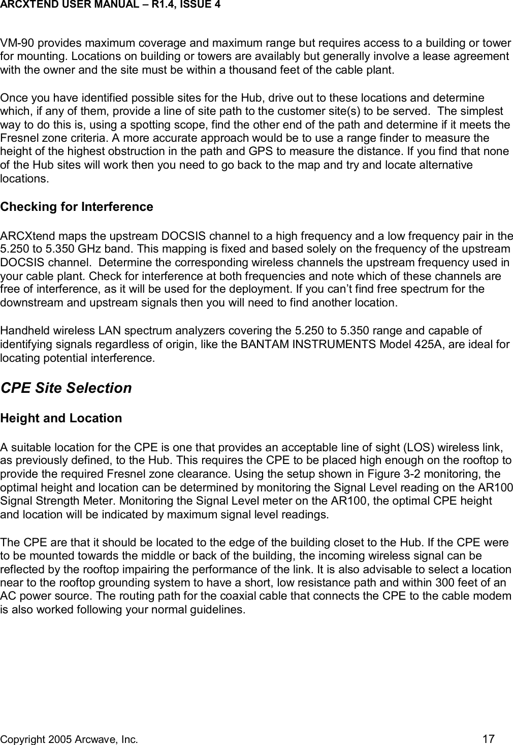
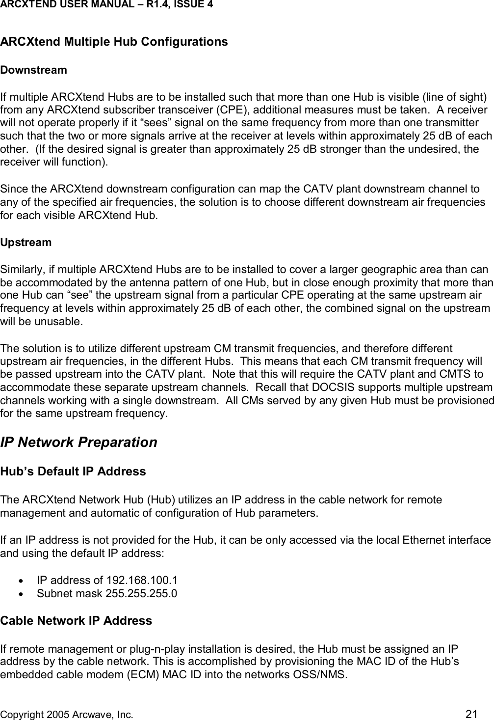
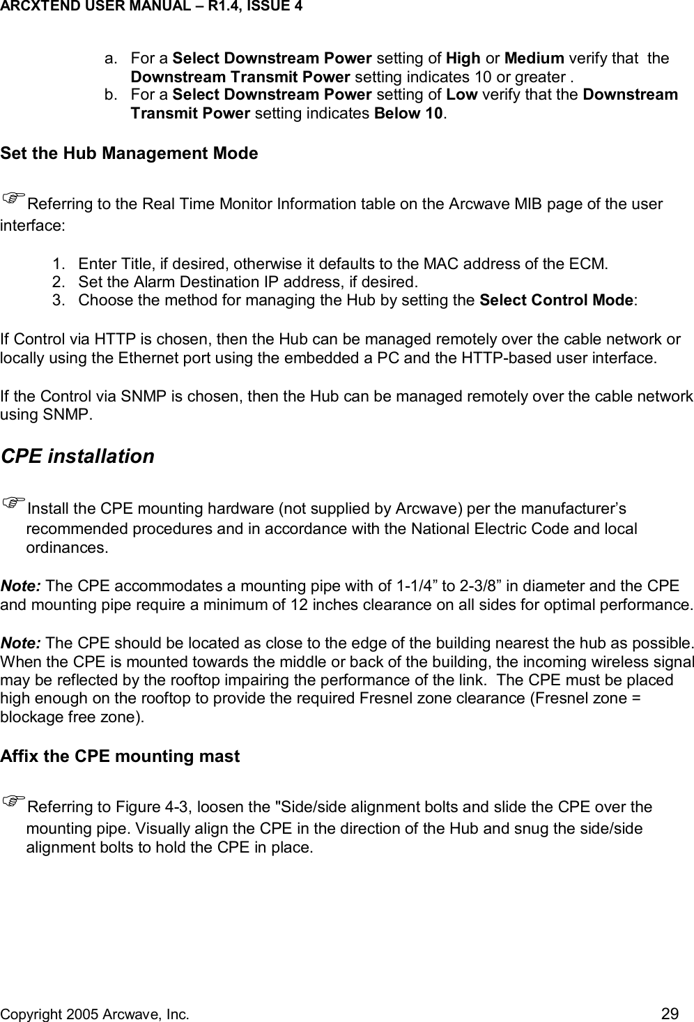
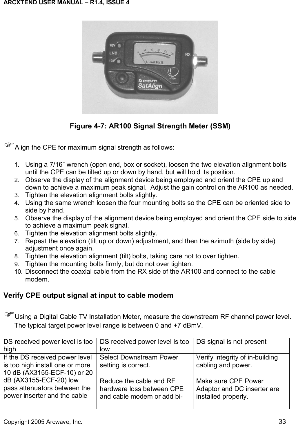
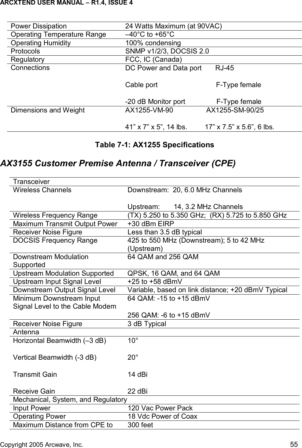
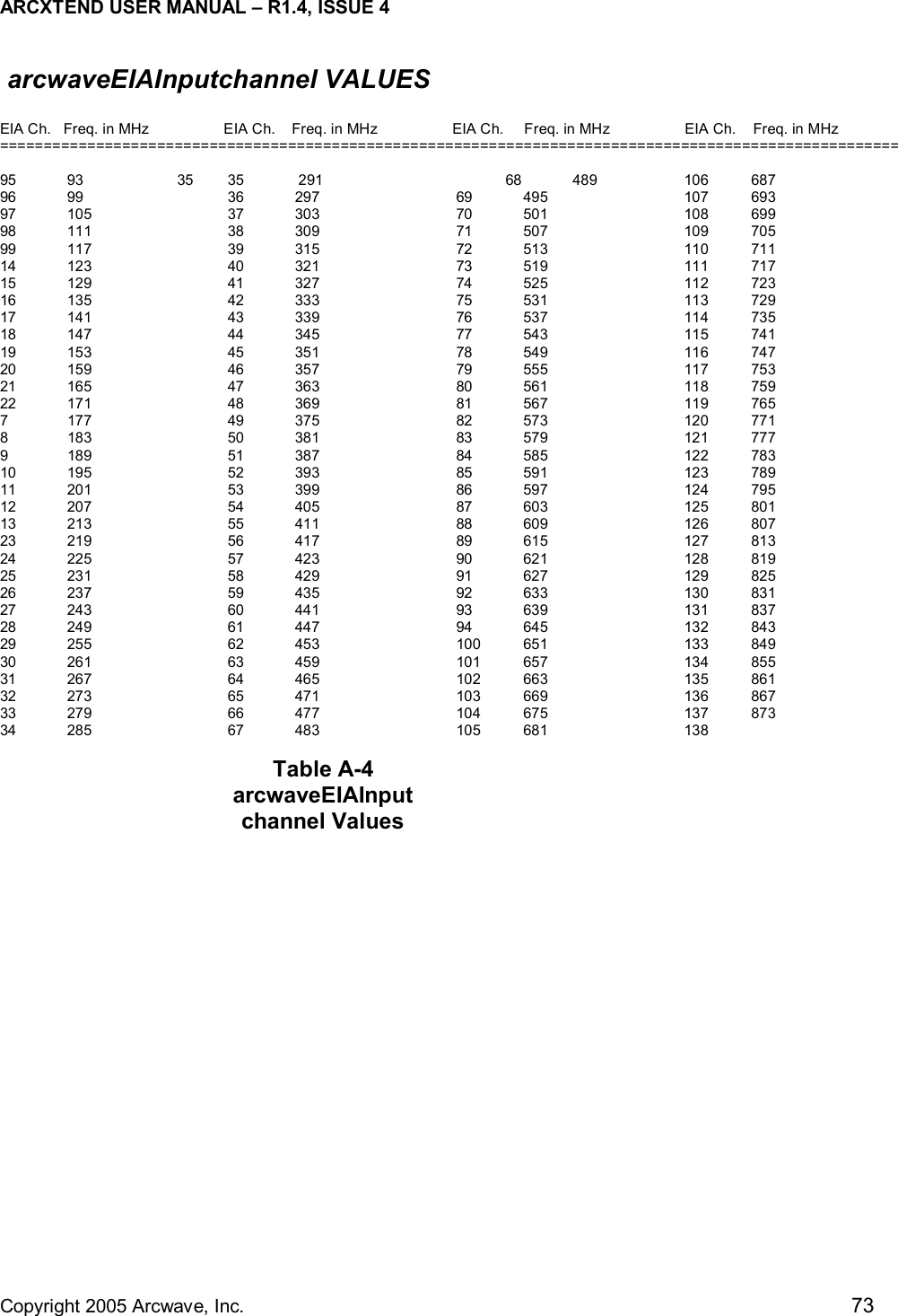
![ARCXTEND USER MANUAL – R1.4, ISSUE 4 Copyright 2005 Arcwave, Inc. 19 TapCATV PlantARCXtendSubscriberTransceiverCable ModemARCXtendHubTransceiverCATV ChannelEIA Channels 7 - 13490 MHz - 855 MHzARCXtend Air Frequency5729 MHz - 5843 MHzCM Receive Frequency429 MHz - 543 MHzLAN or USBChannel Plan Downstream Configuration The ARCXtend downstream block diagram is illustrated in Figure 3-3. Note that the North American DOCSIS 64 QAM or 256 QAM downstream signal is 5.25 MHz wide and is transported within a standard 6 MHz wide channel throughout the CATV plant and the ARCXtend system. All downstream frequencies indicated are the center frequency of the 6 MHz wide channel. Figure 3-3: ARCXtend Downstream Block Diagram Downstream Block Diagram The DOCSIS cable modem downstream channel on the CATV plant is already established in the working cable modem system. At the time of installation the ARCXtend Hub is automatically configured to the CATV downstream channel. Any EIA channel between 7 and 134, inclusive, may be utilized. Table A-3 in Appendix A provides a list of these channels and their corresponding center frequencies. The downstream output of the ARCXtend Hub is the over-the-air frequency in the range of 5729 MHz through 5843 MHz. Any frequency in this range can be chosen from Table 3-4, which determines the corresponding cable modem receive frequency. Note from the table that the cable modem downstream receive frequency is always [air frequency – 5300 MHz]. The ARCXtend standard downstream air frequencies were chosen to ensure that the corresponding cable modem downstream receive frequencies are centered on standard EIA CATV channels to enable the fastest possible cable modem downstream scan. In summary, any CATV downstream channel may be employed as input into the Hub, and any specified air frequency between 5729 and 5843 MHz may be chosen, but the cable modem receive frequency (channel) is determined from the air frequency only. Note that the downstream CATV](https://usermanual.wiki/Arcwave/AX1255/User-Guide-515966-Page-28.png)
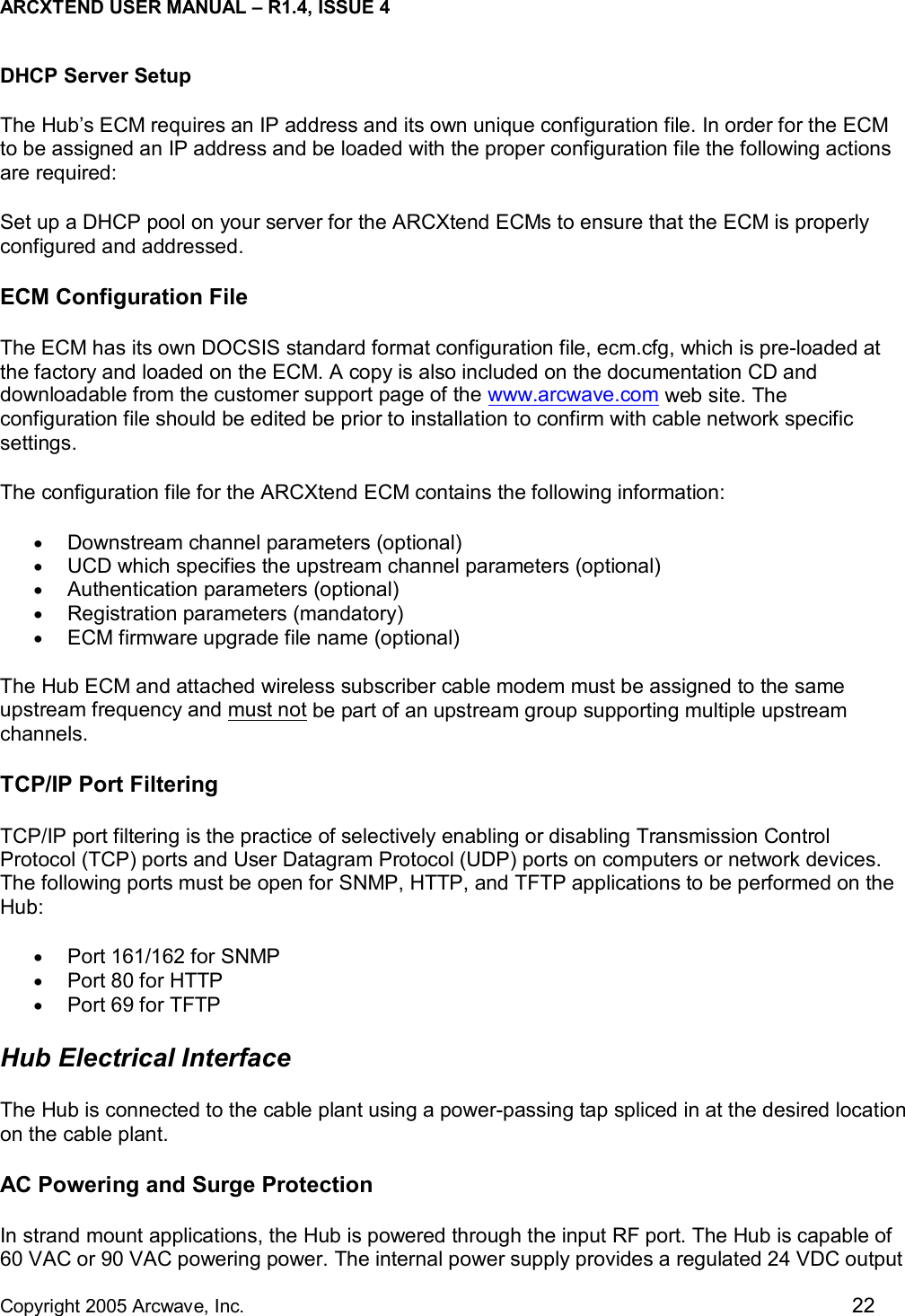
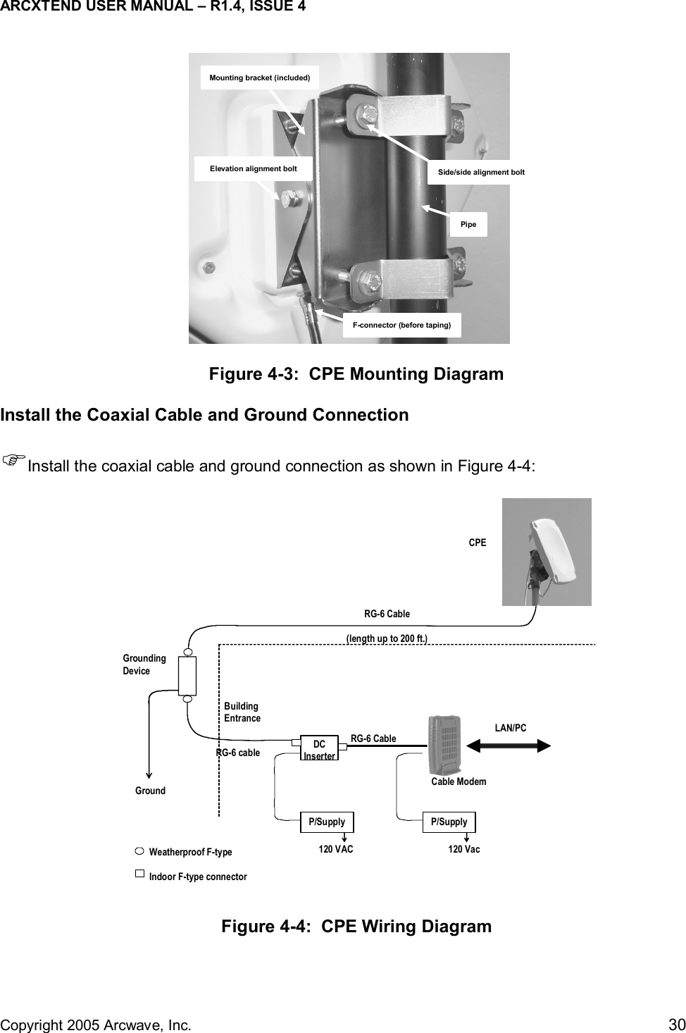
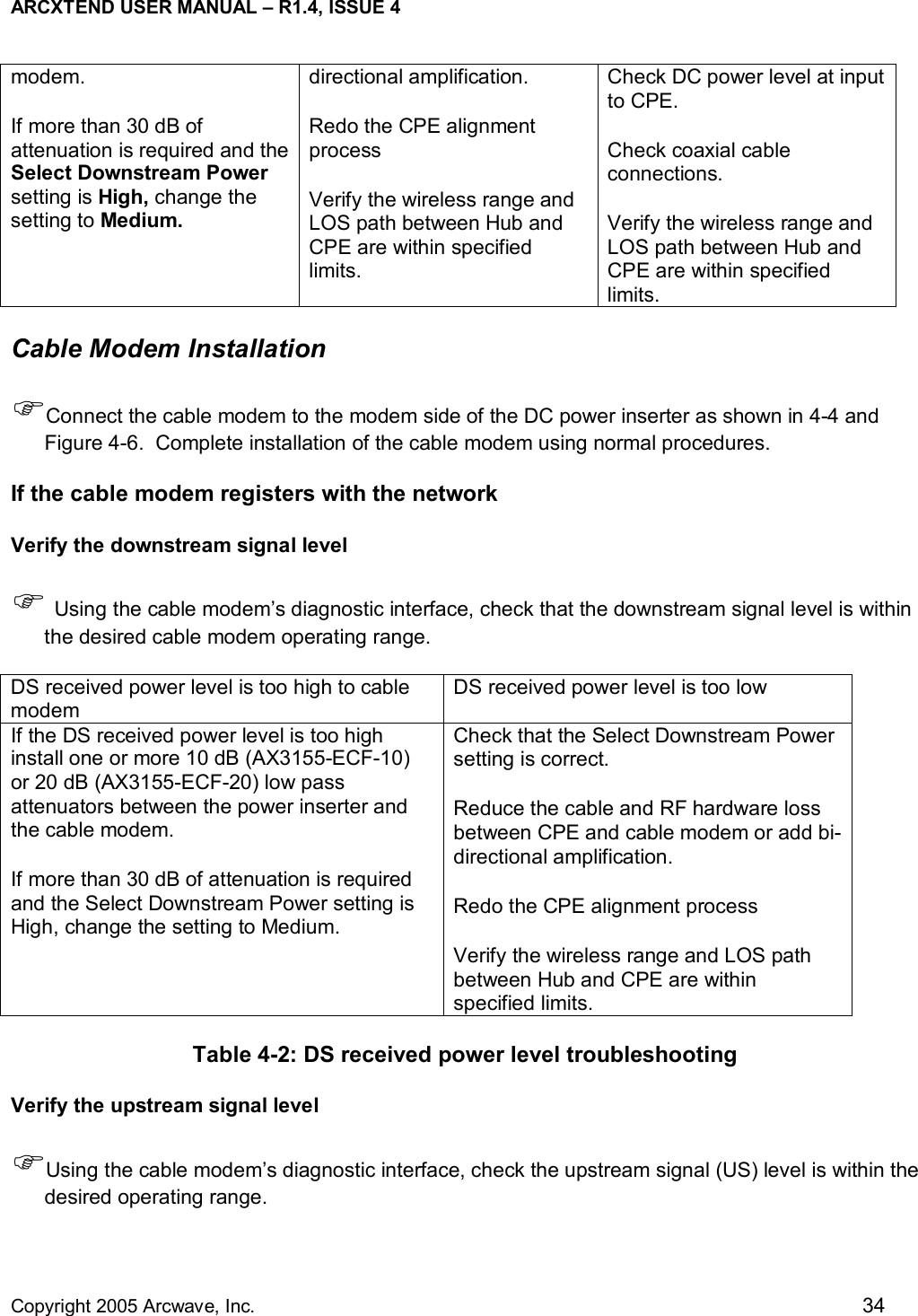
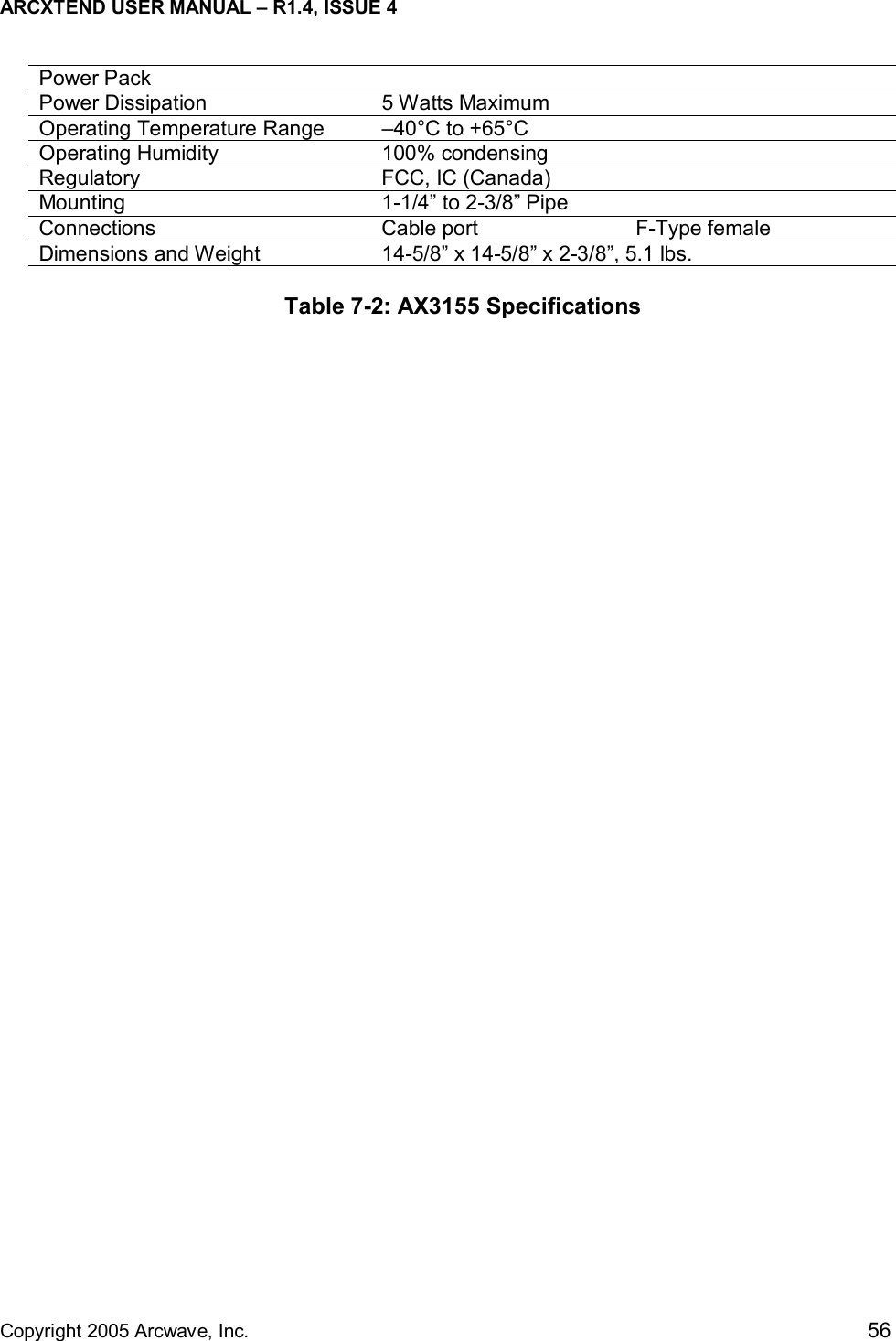
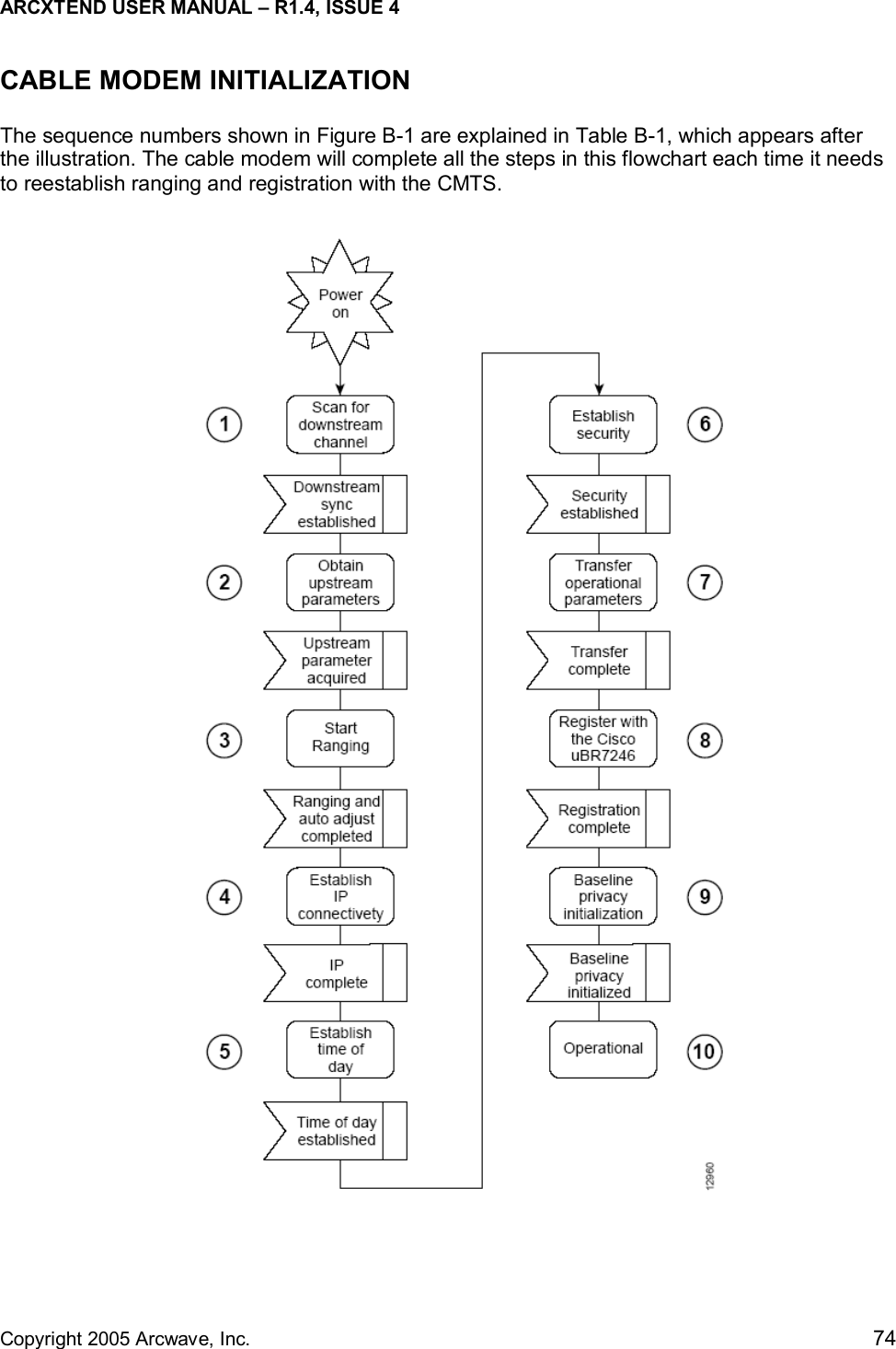
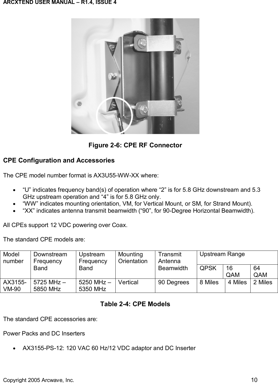
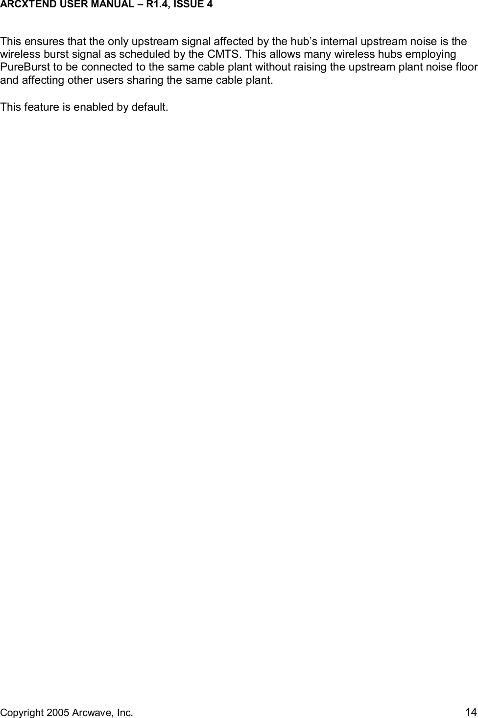
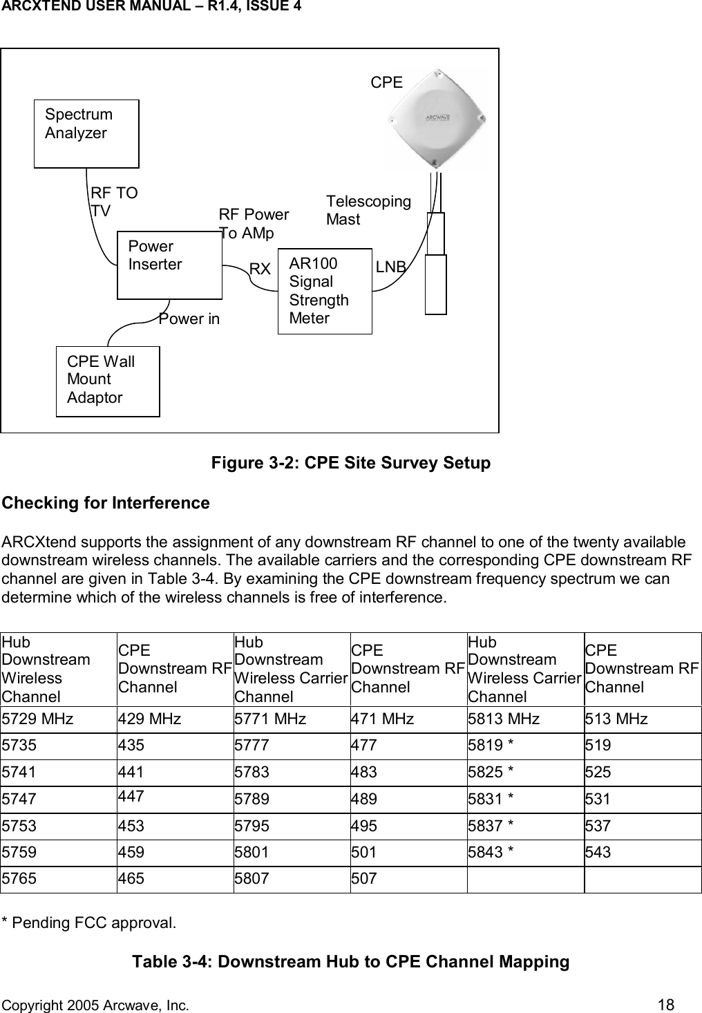
![ARCXTEND USER MANUAL – R1.4, ISSUE 4 Copyright 2005 Arcwave, Inc. 20 TapCATV PlantARCXtendSubscriberTransceiverCable ModemARCXtendHubTransceiverCATV UpstreamFrequency5 MHz - 42 MHzARCXtend Air Frequency5258 MHz - 5342 MHzCM TransmitFrequency5 MHz - 42 MHzLAN or USBfrequency may be different than the cable modem receive frequency. This is generally not a concern as most DOCSIS systems on which there is only one DOCSIS downstream channel on the cable network do not specify the CM receive frequency in the CM configuration file, rather they let the CM find the downstream on its own. Upstream Configuration The ARCXtend upstream block diagram is illustrated in Figure 4-2. Note that the North American DOCSIS (Version 1.0 and 1.1) QPSK or QAM upstream signal is up to 3.2 MHz wide. DOCSIS 2.0 upstream signals can be as much as 6.4 MHz wide. All frequencies specified in this section are the center frequency of the particular signal. Figure 3-4: ARCXtend Upstream Block Diagram Upstream Block Diagram The cable modem (CM) is commanded by the downstream signal to transmit at a specific upstream frequency between 5 MHz and 42 MHz. Note that any upstream frequency may be selected. Refer to Figure 3-4 from right to left. The ARCXtend Subscriber Transceiver (CPE) up converts the CM upstream signal to the 5300 MHz band and transmits two copies of the signal: 5300 MHz-[CM transmit frequency] and 5300 MHz+[CM transmit frequency]. For example, if the CM upstream transmits frequency is 22.5 MHz; the ARCXtend CPE will simultaneously transmit the signal on two air frequencies: 5277.5 MHz and 5322.5 MHz. In summary, the CM upstream transmit frequency determines the two upstream air frequencies transmitted by the ARCXtend CPE. The ARCXtend Hub selects either the high or low air frequency and passes the user data upstream to the CATV plant at the original CM transmit frequency.](https://usermanual.wiki/Arcwave/AX1255/User-Guide-515966-Page-29.png)