Asis Technologies NAVIKEY Reader User Manual P908 manualx
Asis Technologies Pte Ltd Reader P908 manualx
UserManual.wiki
>
Asis Technologies
>
NAVIKEY User Manual
Users Manual
Navigation menu
Upload a User Manual
Namespaces
Wiki Guide
HTML
PDF
Info
Views
User Manual
Discussion / Help
Navigation


![Page | 41 8.1 NaviKey Operation Navikey allow localize configuration of Controller without the need to external peripherals. All is needed is finger to touch the keypad to get info of controller and make configuration. Features of Navi key includes, live event display, device control, card enroll (csn only), controller parameter setting. Navigate the Navikey using the keypad KEY 2 = UP, KEY 8 = DOWN, KEY 4 = LEFT, KEY 6 = RIGHT. Back and Enter KEY is use to get into an function or exit from the function. Default Screen of Navi key always show latest controller generated event From default screen press [KEY 4] 2 x to view it configured network parameters.](https://usermanual.wiki/Asis-Technologies/NAVIKEY/User-Guide-3628523-Page-45.png)
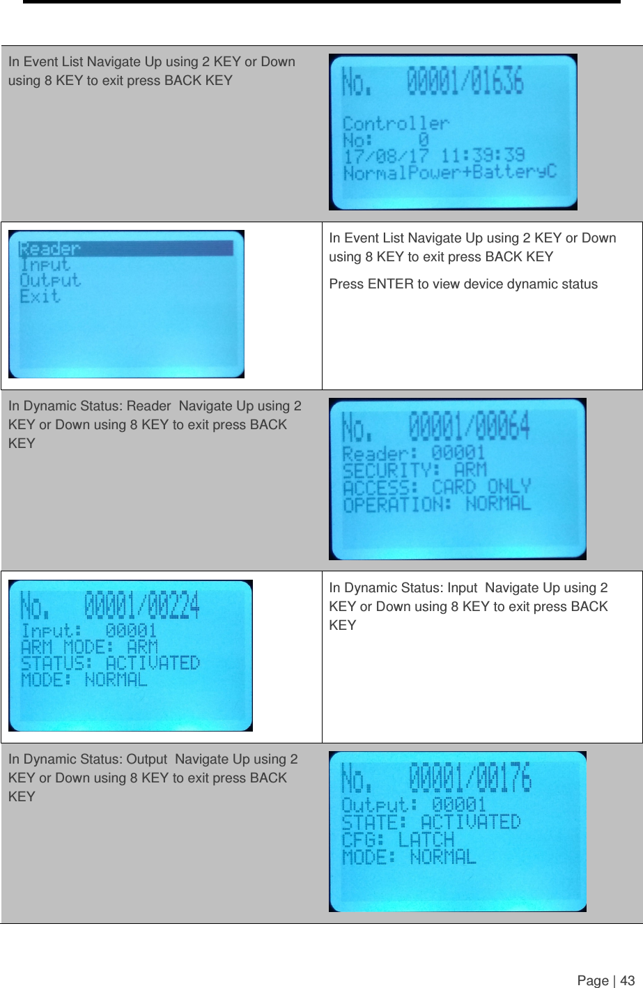
![Page | 42 From default screen press [KEY 4] 3 x to view system operating parameters. Firmware version Date / Time Card Event To view recent Card event Press [[<4 key]] left 4 times. Use key 2 to navigate up or key 8 to navigate down. To exit press BACK key To view recent Reader event Continue from Card Event after the BACK key press <4 key will bring to Output, press BACK key and press <4 key, will bring to Input Event, press BACK and press <4 key will bring to READER event Use key 2 to navigate up or key 8 to navigate down. To exit press BACK key To get into Command Mode press <4 key 1 time. Press ENTER key You will be prompt with password press 123456 and press ENTER key In Command Mode Navigate Up using 2 KEY or Down using 8 KEY to exit press BACK KEY Press ENTER KEY to get into the selected function](https://usermanual.wiki/Asis-Technologies/NAVIKEY/User-Guide-3628523-Page-46.png)