Atlas Copco BLM s r l F6X Controller Unit For MWR Wrenches User Manual Focus 60 Focus 61 User Guide
SALTUS Industrial Technique GmbH Controller Unit For MWR Wrenches Focus 60 Focus 61 User Guide
UserManual.wiki
>
Atlas Copco BLM s r l
>
F6X User Manual
Users manual
Navigation menu
Upload a User Manual
Namespaces
Wiki Guide
HTML
PDF
Info
Views
User Manual
Discussion / Help
Navigation
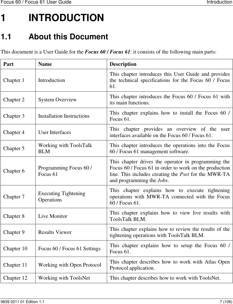
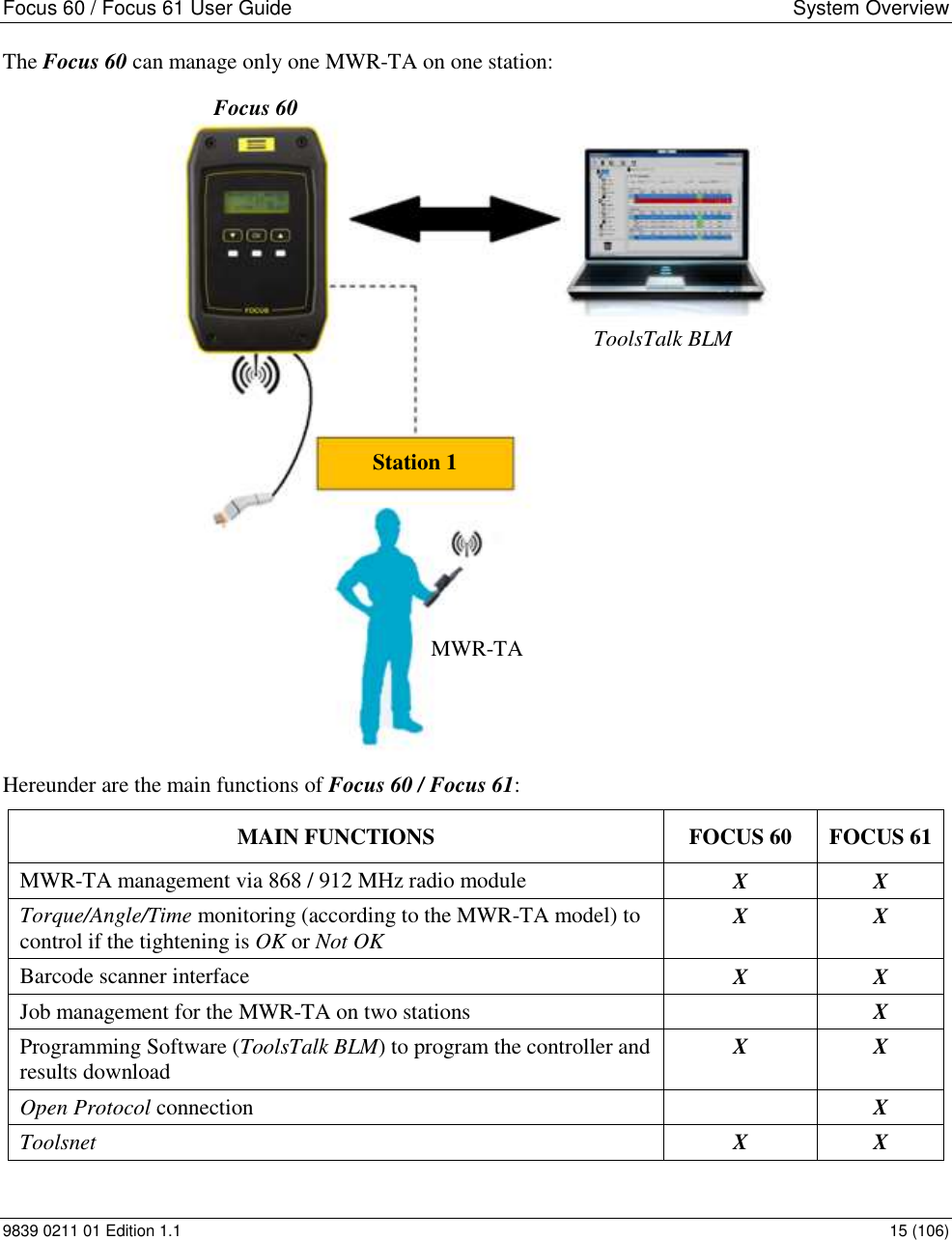
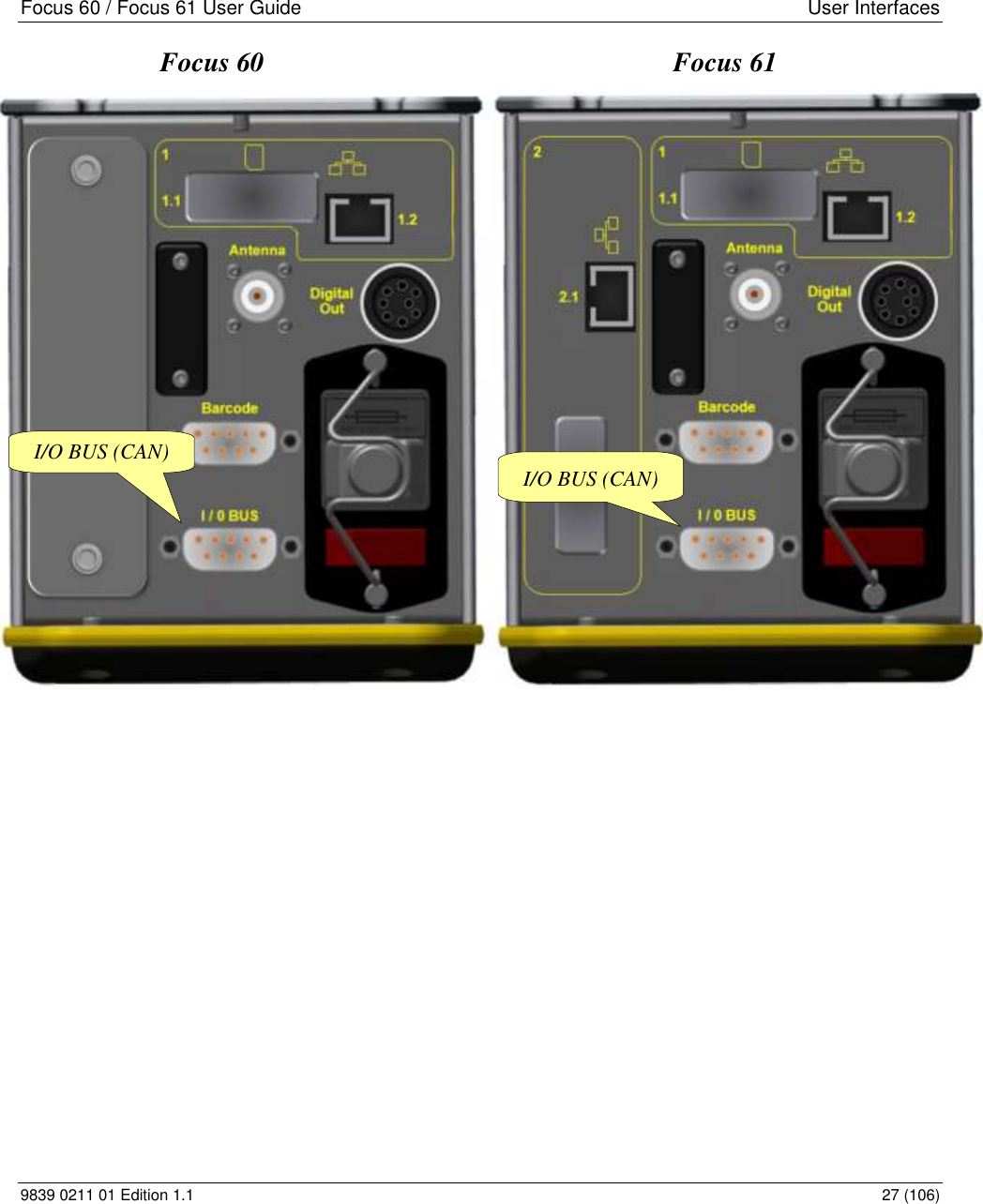
![Focus 60 / Focus 61 User Guide Introduction 9839 0211 01 Edition 1.1 9 (106) DIMENSIONS The unit of the dimensions is in mm. INTERFACES Ethernet ports Barcode Scanner interface (RS232) I / O BUS (CAN) Wave Flexible Antenna connector Radio module frequencies: Country Number Channel Frequency [MHz] Data rate [bit/s] Europe 1 51 868.034 38400 2 56 868.297 38400 3 60 868.502 38400 4 64 868.706 38400 5 69 869.006 38400 6 76 869.273 38400](https://usermanual.wiki/Atlas-Copco-BLM-s-r-l/F6X/User-Guide-3383928-Page-9.png)
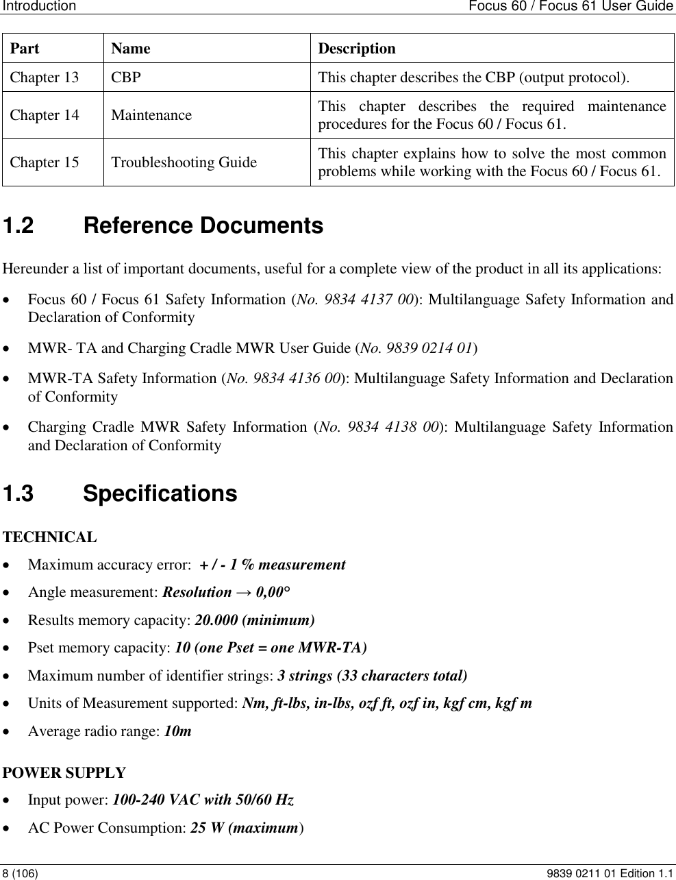
![Introduction Focus 60 / Focus 61 User Guide 10 (106) 9839 0211 01 Edition 1.1 Country Number Channel Frequency [MHz] Data rate [bit/s] 7 82 869.573 38400 8 84 869.840 38400 9 51 868.034 19200 10 56 868.297 19200 11 60 868.502 19200 12 64 868.706 19200 13 69 869.006 19200 14 76 869.273 19200 15 82 869.573 19200 16 84 869.840 19200 USA 1 2 902.791 38400 2 9 906.478 38400 3 10 907.004 38400 4 17 910.691 38400 5 20 912.271 38400 6 31 918.064 38400 7 32 918.590 38400 8 46 925.963 38400 9 2 902.791 19200 10 9 906.478 19200 11 10 907.004 19200 12 17 910.691 19200 13 20 912.271 19200 14 31 918.064 19200 15 32 918.590 19200 16 46 925.963 19200](https://usermanual.wiki/Atlas-Copco-BLM-s-r-l/F6X/User-Guide-3383928-Page-10.png)