Aviat Networks IRU600V4 IRU 600v4 MP User Manual
Aviat Networks (S) Pte. Ltd IRU 600v4 MP
UserManual.wiki
>
Aviat Networks
>
IRU600V4 User Manual
User Manual
Navigation menu
Upload a User Manual
Namespaces
Wiki Guide
HTML
PDF
Info
Views
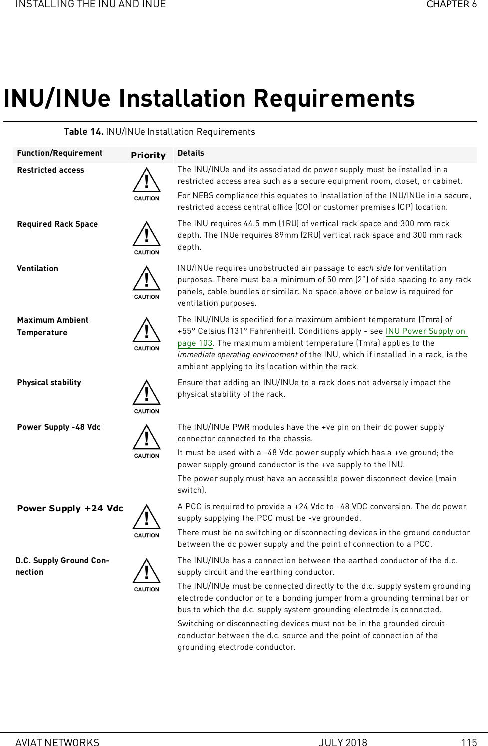
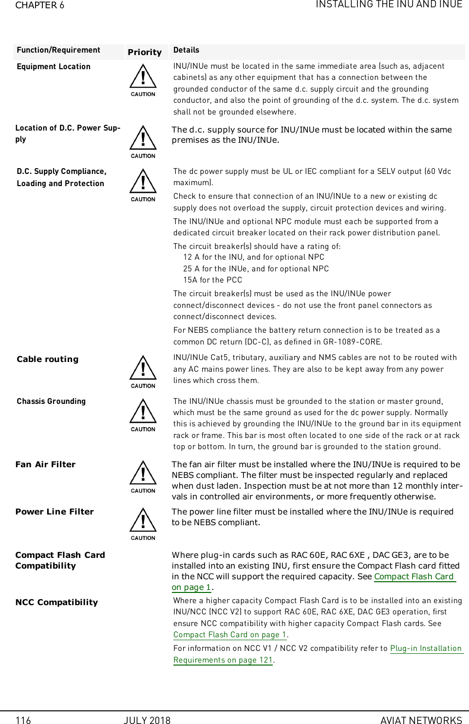
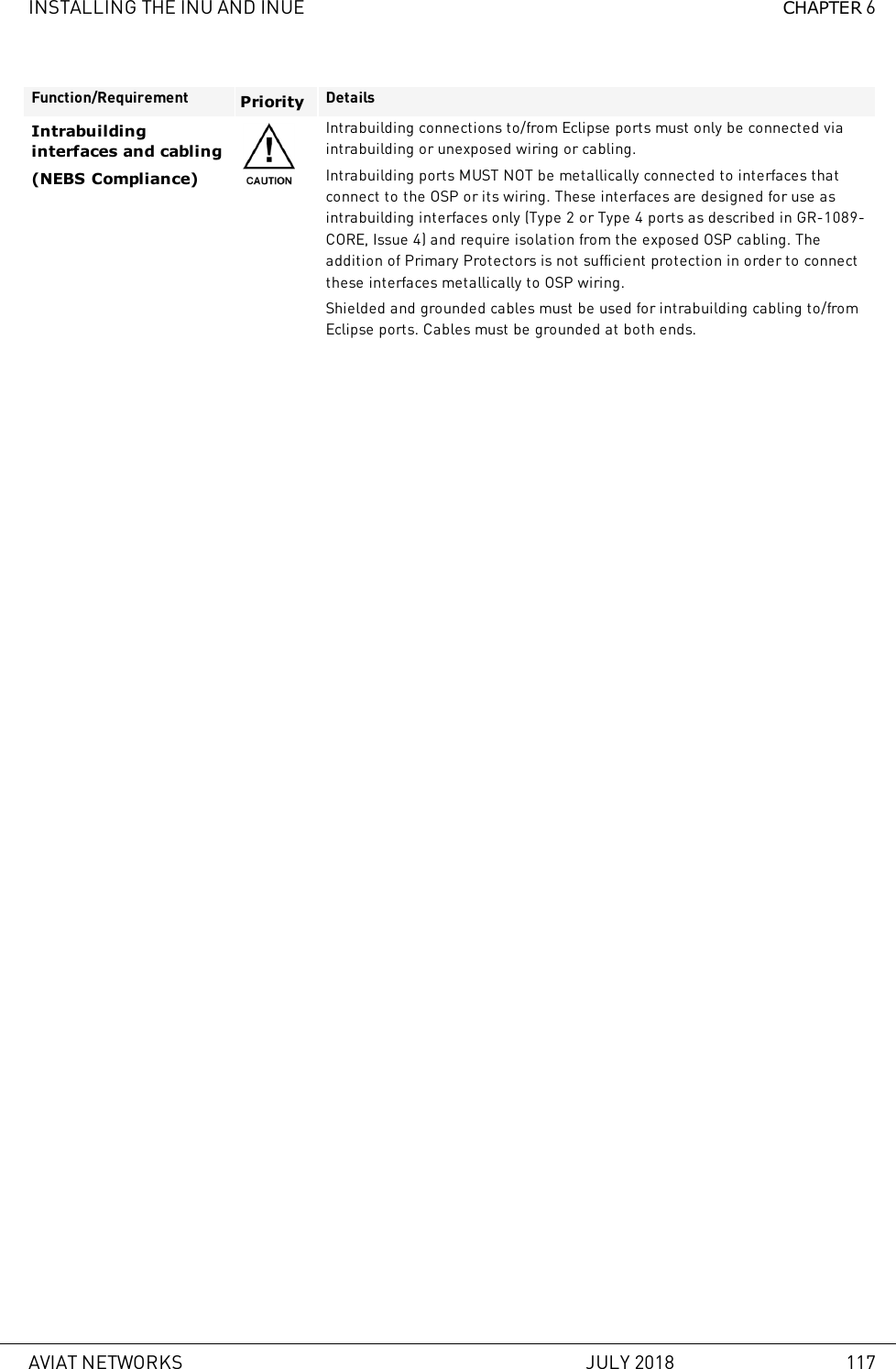
User Manual
Discussion / Help
Navigation