Aviation Communications and Surveillance Systems NXTXPONDER ATCRBS/Mode S Transponder User Manual System Description Installation Manual SDIM
Aviation Communications and Surveillance Systems (ACSS), LLC. ATCRBS/Mode S Transponder System Description Installation Manual SDIM
System Description & Installation Manual (SDIM)


![SYSTEM DESCRIPTION AND INSTALLATION MANUAL NXT-600 Mode S/ADS-B Transponder/Part No. 9006000 Since interface requirements are often interpreted differently by equipment manufacturers when they are implemented, the transponder has been designed to interface with the ACSS TCAS II systems, as well as major competitors' TCAS II systems. C. ADLP Interface, ADLP Function, and Transponder Level The initial implementation of the NXT-600 Transponder is a Level 3 transponder according to the definitions in DO-181E and ICAO Annex 10. It can process COMM-A/B Data Link messages and it interfaces to an external Mode S Airborne Data Link Processor (ADLP) to process COMM C Data Link messages, which is defined functionally by RTCA DO-218B. The NXT-600 Transponder contains four High Speed ARINC 429 Data Buses, a COMM-A/B Input and Output Bus, and a COMM-C Input and Output Bus. COMM-A Data received by the transponder in an interrogation is transferred to the ADLP on the COMM-A/B data bus; COMM-B data received from the ADLP is transmitted in replies to interrogations. In a similar manner, COMM-C Data received by the transponder in an UELM interrogation is transferred to the ADLP on the COMM-C data bus. D. Altimeter Interface The NXT-600 Transponder can accept uncorrected pressure altitude inputs from altimeter or air data systems. The transponder has dual interfaces for ARINC 429 Air Data and ARINC 575 Air Data Systems. The transponder contains two independent inputs for each source and a discrete input for source selection. E. Controller Interface The NXT-600 Transponder is controlled from a standard Mode S or Mode S/TCAS control panel through an ARINC 429 input data bus and discrete inputs and outputs. The control panel interface is defined in ARINC 718A-4. However, several variations exist for different customers and airlines. The NXT-600 Transponder interfaces to all commonly used Mode S and Mode S/TCAS control panels. The NXT-600 Transponder has a dedicated low speed ARINC 429 data input for receiving the Aircraft Identification Subfield (AIS) Flight Identification from another aircraft system (i.e., a Flight Management System [FMS] or Onboard Maintenance System [OMS]). The flight ID can also be received on any one of the five DAPS buses (high or low speed) or from the control panel on the control data bus (low speed). The flight identification can be the aircraft’s flight identifier or registration. F. GPS Interface The NXT-600 Transponder has two dedicated ARINC 429 data inputs for receiving the required GPS parameters to support the ADS-B OUT functionality. These ARINC 429 buses must be used to input (high or low speed) GPS label information directly from a qualified source, as specified in FAA AC 20-165A, for ADS-B OUT enabled aircraft. 1-6 26 Mar 2014 34-52-13 Pub. No. 8600600-001, Revision 001 Use or disclosure of information on this page is subject to the restrictions in the proprietary notice of this document.](https://usermanual.wiki/Aviation-Communications-and-Surveillance-Systems/NXTXPONDER/User-Guide-2377076-Page-32.png)
![SYSTEM DESCRIPTION AND INSTALLATION MANUAL NXT-600 Mode S/ADS-B Transponder/Part No. 9006000 (b) Traffic Alert and Collision Avoidance System Mode S transponders are an integral part of the Traffic Alert and Collision Avoidance System (TCAS). TCAS-equipped aircraft are airborne interrogators, communicating with other TCAS-equipped aircraft through their Mode S transponders for coordination of collision avoidance maneuvers. TCAS aircraft acquire other Mode S transponder-equipped aircraft by receiving squitter transmissions (unsolicited All-Call type replies, transmitted pseudo-randomly every 0.8 to 1.2 seconds with aircraft Mode S address), and thereafter by specific addressed interrogations. Although either Mode S or ATCRBS Mode C transponders aid TCAS-equipped aircraft in avoiding collisions, coordination of collision avoidance maneuvers is possible between two aircraft only if both are Mode S and TCAS equipped. (c) Mode S Message 1. Interrogation and Reply Formats Mode S features have been added to the ATCRBS already in place. This procedure ensures that the older airborne transponders and the ground-based interrogators used in the ATCRBS are still functional. The Mode S signal formats used for this combined system operation include ATCRBS/Mode S All-Call [Mode A, Mode C, and Mode S], Mode S interrogation, Mode S SLS and Mode S reply. 2. Interrogation Pulses and Timing The uplink Mode S format for the interrogation pulse group consists of pulses designated P1, P2, and P3. The time spacing between the P1 and P3 pulses determines the type of interrogation (Mode A aircraft identification or Mode C altitude reporting). Pulse P2, which follows P1 by 2 microseconds, is used for Side Lobe Suppression (SLS) in the ATCRBS. The amplitude of P2 is recognized by the airborne transponder as either a main beam or SLS interrogation. With Mode S interrogation, the basic P1 and P3 pulse system is extended to include a P4 pulse, which follows P3 by 2 microseconds. The P4 pulse uses the same spacing as between P1 and P2. However, P4 has an additional feature in that its pulse width can be either 1.6 microseconds or 0.8 microsecond, whereas the P1 and P3 pulse widths are always 0.8 microsecond. 3. Replies to All-Call Interrogations and Pulse Width In operation, when a standard ATCRBS transponder receives this interrogation of P1, P3, and P4 pulses, it responds with the ATCRBS reply, which consists of 14 pulses that carry the identity code or the altitude code. The P4 pulse is ignored since the ATCRBS transponder circuit is designed so that it does not recognize the P4 pulse. The response is dependent upon the presence and length of P4. When a standard P1 and P3 interrogation is received from an ATCRBS interrogator (no P4), the Mode S transponder responds with a standard ATCRBS reply. An uplink interrogation pulse group, which includes a P4 pulse, makes the Mode S transponder prepare to measure the P4 pulse width. As soon as the Mode S transponder detects the rising edge of the P4 pulse, it disables its ATCRBS reply. Pub. No. 8600600-001, Revision 001 34-52-13 1-27 26 Mar 2014 Use or disclosure of information on this page is subject to the restrictions in the proprietary notice of this document.](https://usermanual.wiki/Aviation-Communications-and-Surveillance-Systems/NXTXPONDER/User-Guide-2377076-Page-53.png)
![SYSTEM DESCRIPTION AND INSTALLATION MANUAL NXT-600 Mode S/ADS-B Transponder/Part No. 9006000 Table 1-27: BDS 6,5 Extended Squitter, Aircraft Operational Status, Surface (cont) Bits Parameter Parameter Data External Source(s) 55 SIL Supplement 0, 1 56 Reserved D. Mode S Message Format and Data Field Definition Refer to RTCA DO-181E, DO-185B, DO-218B, and DO-260B for further details of Mode S Message Formats and Field definitions. Table 1-28 defines the Mode S interrogation UF (Uplink Format) messages and Table 1-29 defines the Mode S reply DF (Downlink Format) messages. The first 5 bits of the message indicate the UF/DF type. The message structure including the number of bits per subfield is included in Table 1-28 and Table 1-29. For example, UF=0 [Binary 00000] is composed of X:3 (3 bits assigned as padding), RL:1 (1 bit assigned to Reply Length) etc. The Uplink Format message field descriptions are listed in Table 1-30 and the Downlink Format message field descriptions are listed in Table 1-31. Table 1-28: Uplink Format Messages Uplink Format Field Description Message Format with Number of Bits UF=0 [00000] Short Air-Air Surveillance X:3, RL:1, X:4, AQ:1, DS:8, X:10 AP:24 X:Pad UF=4 [00100] Surveillance, Altitude Request PC:3, RR:5, DI:3, SD:16, AP:24 UF=5 [00101] Surveillance, Identity Request PC:3, RR:5, DI:3, SD:16, AP:24 UF=11 [01011] Mode S Only All-Call PR:4, II/IC:4, CL:3, X:16, AP:24 X:Pad UF=16 [10000] Long Air-Air Surveillance X:3, RL:1, X:4, AQ:1, X:18, MU:56, AP:24 X:Pad UF=20 [10100] Comm-A, Altitude Request PC:3, RR:5, DI:3, SD:16, MA:56, AP:24 UF=21 [10101] Comm-A, Identity Request PC:3, RR:5, DI:3, SD:16, MA:56, AP:24 NOTE: PC, RR, DI, and SD subfields are undefined for UF=20/21 broadcast interrogations. Pub. No. 8600600-001, Revision 001 34-52-13 1-51 26 Mar 2014 Use or disclosure of information on this page is subject to the restrictions in the proprietary notice of this document.](https://usermanual.wiki/Aviation-Communications-and-Surveillance-Systems/NXTXPONDER/User-Guide-2377076-Page-77.png)
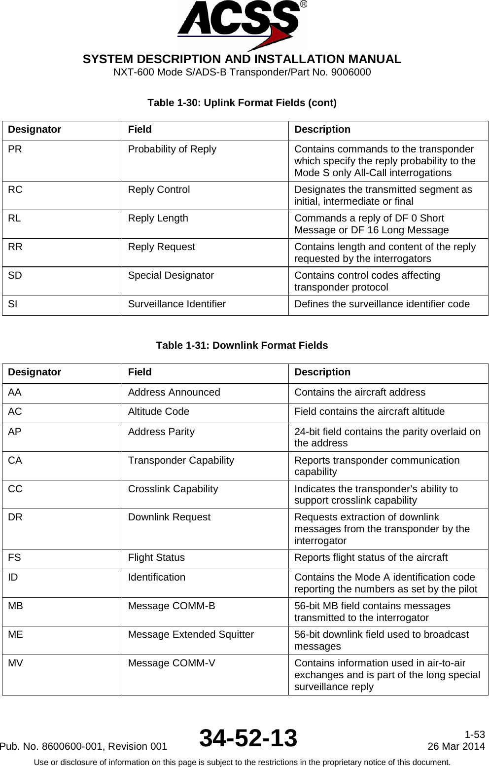
![SYSTEM DESCRIPTION AND INSTALLATION MANUAL NXT-600 Mode S/ADS-B Transponder/Part No. 9006000 Table 1-29: Downlink Format Messages Downlink Format Field Description Message Format with Number of Bits DF 0 [00000] Short Air-Air Surveillance VS:1, CC:1, X:1, SL:3, X:2, RI:4, X:2, AC:13, AP:24 X:Pad DF 4 [00100] Surveillance, Altitude Reply FS:3, DR:5, UM:6, AC:13, AP:24 DF 5 [00101] Surveillance, Identity Reply FS:3, DR:5, UM:6, ID:13, AP:24 DF 11 [01011] All-Call Reply CA:3, AA:24, PI:24 DF 16 [10000] Long Air-Air Surveillance VS:1, X:2, SL:3, X:2, RI:4, X:2, AC:13, MV:56, AP:24 X:Pad DF 17 [10001] Extended Squitter (ADS-B) CA:3, AA:24, ME:56, PI:24 DF 20 [10100] Comm-B, Altitude Reply FS:3, DR:5, UM:6, AC:13, MB:56, AP:24 DF 21 [10101] Comm-B, Identity Reply FS:3, DR:5, UM:6, ID:13, MB:56, AP:24 Table 1-30: Uplink Format Fields Designator Field Description AP Address Parity 24-bit discrete address with parity check bits overlaid AQ Acquisition Designates formats UF=0, 16 as acquisition transmissions or non-acquisition. CL Code Label Identifies the contents of the IC field DI Designator Identification Identifies the coding contained in the SD field DS COMM-B Data Selector Contains the identity of the ground-initiated COMM-B register IC Interrogator Code Contains either the II Code or SI Code II Interrogator Identification Identifies the interrogator MA Message COMM-A 56-bit uplink field contains messages directed to the aircraft MU Message COMM-U 56-bit uplink field contains information used in air-to-air exchanges part of the long special surveillance interrogation NC Number of C Segments Number of segments transmitted in ELM mode and part of a COMM-C interrogation PC Protocol Operating commands to the transponder 1-52 26 Mar 2014 34-52-13 Pub. No. 8600600-001, Revision 001 Use or disclosure of information on this page is subject to the restrictions in the proprietary notice of this document.](https://usermanual.wiki/Aviation-Communications-and-Surveillance-Systems/NXTXPONDER/User-Guide-2377076-Page-78.png)
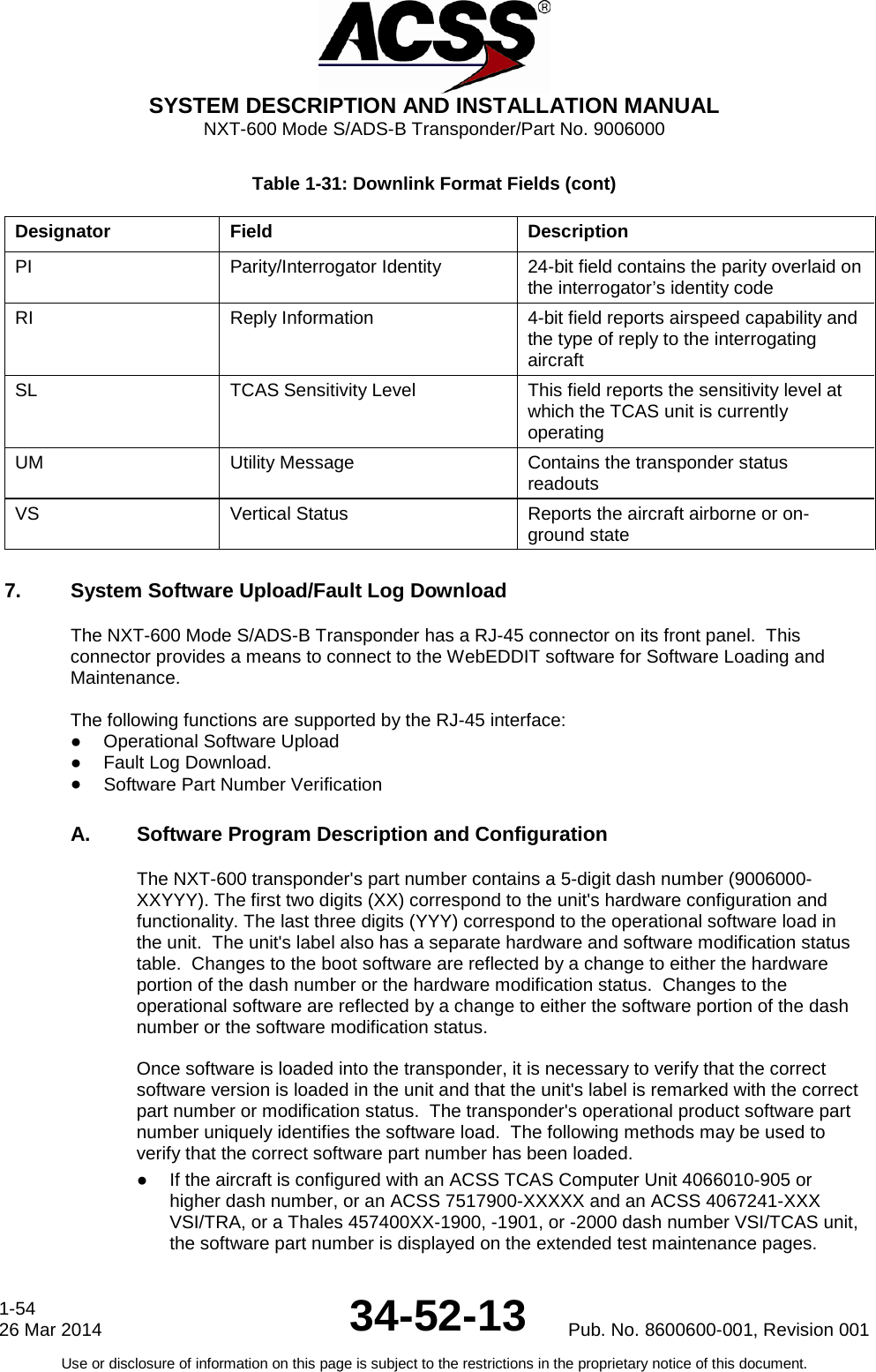


![SYSTEM DESCRIPTION AND INSTALLATION MANUAL NXT-600 Mode S/ADS-B Transponder/Part No. 9006000 Table 4-1: NXT-600 Mode S/ADS-B Transponder Loading/Gradient Specifications (cont) Connector Pin Designation Functional Description J1-11, 12, 21 Configuration Data Program Inputs: Reference subsection 3 for the functional descriptions. J1-17 thru J1-20 DC GROUND: To be connected to aircraft dc ground. J1-23 XPDR VALID (PO) OUTPUT: This discrete outputs the status of the transponder continuous monitor tests. A +28 V dc (200 mA maximum) is provided when the transponder is operational and an active transponder mode is selected. An OPEN (>100k ohms resistance to GROUND) output is provided when the transponder has failed. This pin should be connected to the control panel XPDR FAIL input for installations requiring a positive/open logic. J1-26, J1-27 ARINC 429 XT Coordination Bus Output: (J1-26 [A], J1-27 [B]) See pins J1-40/41 for ARINC 429 TX Coordination Bus Input. The following labels are outputs to TCAS: Label Description 013 TCAS Display Mode and Range Control 015 TCAS Altitude Limit Control 016 Transponder and TCAS Control 203 Pressure Altitude 204 Baro Corrected Altitude 270 BDS Register Data 271 TCAS Coordination Data Word 1 272 TCAS Coordination Data Word 2 273 Mode S Ground Uplink 274 TCAS Coordination Data Word 3 275 Mode S Address Word 1 276 Mode S Address/Max TAS Word 2 277 ACK/NAK of Non-Periodic Message 350 TCAS Bit Mapped Error Word 356 TCAS Text Data 4-2 26 Mar 2014 34-52-13 Pub. No. 8600600-001, Revision 001 Use or disclosure of information on this page is subject to the restrictions in the proprietary notice of this document.](https://usermanual.wiki/Aviation-Communications-and-Surveillance-Systems/NXTXPONDER/User-Guide-2377076-Page-108.png)
![SYSTEM DESCRIPTION AND INSTALLATION MANUAL NXT-600 Mode S/ADS-B Transponder/Part No. 9006000 Table 4-1: NXT-600 Mode S/ADS-B Transponder Loading/Gradient Specifications (cont) Connector Pin Designation Functional Description J1-28, 29 ARINC 429 XPDR to DLP A/B Output: (J1-28 [A], J1-29[B]) This differential pair output is a high speed ARINC 429 bus (100k bits/second nominal) that sends data to an airborne data link processor (ADLP) system. The data bus is used to transfer COMM-A and COMM-B messages between the two systems and conforms to the ARINC 718A-4 standard for ADLP to transponder interface. J1-30, 31 ARINC 429 XPDR to DLP C/D Output: (J1-30 [A], J1-31 [B]) This differential pair output is a high speed ARINC 429 bus (100k bits/second nominal) that sends data to an airborne data link processor (ADLP) system. The data bus is used to transfer COMM-C messages between the two systems and conforms to the ARINC 718A-4 standard for ADLP to transponder interface. J1-32, 33 ARINC 429/575 Air Data Computer #1 Input: (J1-32 [A], J1-33 [B]) This ARINC 429 bus can be used to input (low speed) the following labels used by the transponder to transmit the EHS Heading and Speed Report: Label Description Type 203 Uncorrected Barometric Altitude A429/A575 204 Corrected Barometric Altitude A429/A575 205 MACH No. A429/A575 206 Indicated Airspeed A429/A575 210 True Airspeed A429/A575 212 Barometric Vertical Rate A429/A575 234 Barometric Correction A429 The standards for this interface are defined in ARINC 706. The input accepts either ARINC 429 or 575 data format, which is selected by the altitude type program pin J1-84. The ALT SRC SEL2 (NO) discrete, pin 60, selects either ADC1 or ADC2. Pub. No. 8600600-001, Revision 001 34-52-13 4-3 26 Mar 2014 Use or disclosure of information on this page is subject to the restrictions in the proprietary notice of this document.](https://usermanual.wiki/Aviation-Communications-and-Surveillance-Systems/NXTXPONDER/User-Guide-2377076-Page-109.png)
![SYSTEM DESCRIPTION AND INSTALLATION MANUAL NXT-600 Mode S/ADS-B Transponder/Part No. 9006000 Table 4-1: NXT-600 Mode S/ADS-B Transponder Loading/Gradient Specifications (cont) Connector Pin Designation Functional Description J1-34, 35 ARINC 429 Control Data Port A Bus Input: (J1-34 [A], J1-35 [B]) Control data can be input into the transponder on either of two low-speed ARINC 429 buses (Ports A and B). The port is selected by the Control Data Port Select Input (pin J1-61). This ARINC 429 bus can be used to input (low speed) control and flight identification information contained in the following labels. Also reference pins J1-48/49 for ARINC 429 Control Data Port B Bus Input. Label Description 013 TCAS Display Mode and Range Control 015 TCAS Altitude Limit Control 016 Transponder and TCAS Control 031 Mode S Control Panel Data 233 Flight ID Characters 1 and 2 234 Flight ID Characters 3 and 4 235 Flight ID Characters 5 and 6 236 Flight ID Characters 7 and 8 J1-36/37 ARINC 429 FMC Input: (J1-36 [A], J1-37 [B]) This ARINC 429 bus can be used to input (high or low speed) the following labels from an FMC: Label Description 101 FMS Selected Heading 102 FMS Selected Altitude 377 Equipment ID 233 Flight ID Characters 1 and 2 234 Flight ID Characters 3 and 4 235 Flight ID Characters 5 and 6 236 Flight ID Characters 7 and 8 NOTE: FMS Selected Altitude (Label 102) will only be accepted on the IRS/FMS bus if the Equipment Id (Label 377) is valid and not indicating IRS (04H). 4-4 26 Mar 2014 34-52-13 Pub. No. 8600600-001, Revision 001 Use or disclosure of information on this page is subject to the restrictions in the proprietary notice of this document.](https://usermanual.wiki/Aviation-Communications-and-Surveillance-Systems/NXTXPONDER/User-Guide-2377076-Page-110.png)
![SYSTEM DESCRIPTION AND INSTALLATION MANUAL NXT-600 Mode S/ADS-B Transponder/Part No. 9006000 Table 4-1: NXT-600 Mode S/ADS-B Transponder Loading/Gradient Specifications (cont) Connector Pin Designation Functional Description J1-38/39 ARINC 429 FCC/MCP Input: (J1-36 [A], J1-37 [B]) This ARINC 429 bus can be used to input (high or low speed) the following labels from an FCC/MCP: Label Description 101 MCP Selected Heading 102 MCP Selected Altitude 233 Flight ID Characters 1 and 2 234 Flight ID Characters 3 and 4 235 Flight ID Characters 5 and 6 236 Flight ID Characters 7 and 8 J1-40/41 ARINC 429 TX Coordination Bus Input: (J1-40 [A], J1-41 [B]) This high speed ARINC 429 input bus is provided to interface with a TCAS computer. The standards for this interface are defined in ARINC 735. This input bus also processes label 354 per ARINC 718A-4. See pins J1-26/27 for ARINC 429 XT Coordination Bus Output. The following TCAS labels are inputs to the transponder: Label Description 270 TCAS RA Segment 2 270 TCAS RA Segment 3 270 TCAS Data Link Capability Segment 0 270 TCAS Data Link Capability Segment 1 270 TCAS Data Link Capability Segment 2 270 TCAS Request for BDS Register Data 276 Mode S Address/Max TAS Word 2 305 Version 1, 260B Config Word 0 305 Version 1, 260B Config Word 1 305 Version 1, 260B Config Word 2 273 TCAS Resolution Advisory 274 TCAS Output 275 TCAS ACK / NAK Pub. No. 8600600-001, Revision 001 34-52-13 4-5 26 Mar 2014 Use or disclosure of information on this page is subject to the restrictions in the proprietary notice of this document.](https://usermanual.wiki/Aviation-Communications-and-Surveillance-Systems/NXTXPONDER/User-Guide-2377076-Page-111.png)
![SYSTEM DESCRIPTION AND INSTALLATION MANUAL NXT-600 Mode S/ADS-B Transponder/Part No. 9006000 Table 4-1: NXT-600 Mode S/ADS-B Transponder Loading/Gradient Specifications (cont) Connector Pin Designation Functional Description J1-42/43 ARINC 429 GPS #1 Input: (J1-42 [A], J1-43 [B]) This ARINC 429 bus must be used to input (high or low speed) GPS label information directly from a qualified source, as specified in FAA AC 20-165A, for ADS-B OUT enabled aircraft (J1-59 open). When dual qualified GPS sources are available in a dual NXT-600 transponder installation connect the GPS 1 ARINC 429 bus to J1-42/43 on both transponders and connect the GPS 2 ARINC 429 bus to J1-64/65 on both transponders. Reference pins J1-64/65 for ARINC 429 GPS #2 input. Reference the table below for the list of required GPS labels. Label Description 76 GPS MSL Altitude 103 GPS Track Angle 110 GPS Latitude Coarse 111 GPS Longitude Coarse 112 GPS Ground Speed 120 GPS Latitude Fine 121 GPS Longitude Fine 130 GPS HPL 136 GPS Vertical Figure of Merit (VFOM) 140 UTC Fine 145 Horizontal Velocity Figure of Merit 150 UTC Time 165 GPS Vertical Velocity 166 GPS N/S Velocity 174 GPS E/W Velocity 247 GPS Horizontal Figure of Merit (HFOM) 273 GPS Sensor Status 370 Height Above Ellipsoid 4-6 26 Mar 2014 34-52-13 Pub. No. 8600600-001, Revision 001 Use or disclosure of information on this page is subject to the restrictions in the proprietary notice of this document.](https://usermanual.wiki/Aviation-Communications-and-Surveillance-Systems/NXTXPONDER/User-Guide-2377076-Page-112.png)
![SYSTEM DESCRIPTION AND INSTALLATION MANUAL NXT-600 Mode S/ADS-B Transponder/Part No. 9006000 Table 4-1: NXT-600 Mode S/ADS-B Transponder Loading/Gradient Specifications (cont) Connector Pin Designation Functional Description J1-44, 45 ARINC 429 IRS/FMS Input: (J1-44 [A], J1-45 [B]) This ARINC 429 bus can be used to input (high or low speed) the following labels used by the transponder to transmit the EHS Heading and Speed Report: Label Description 101 FMS Selected Heading 102 FMS Selected Altitude 104 Selected Vertical Speed 233 Flight ID Characters 1 and 2 234 Flight ID Characters 3 and 4 235 Flight ID Characters 5 and 6 236 Flight ID Characters 7 and 8 237 Flight ID Characters 9 and 10 312 Ground Speed 313 True Track Angle 314 True Heading 320 Magnetic Heading 325 Roll Angle 335 Track Angle Rate 365 Vertical Velocity 377 Equipment ID NOTE: FMS Selected Altitude (Label 102) will only be accepted on the IRS/FMS bus if the Equipment ID (Label 377) is valid and not indicating IRS (04H). J1-46,47 ARINC 429/575 Air Data Computer #2 Input: (J1-46 [A], J1-47 [B]) See pins J1-32, 33. J1-48, 49 ARINC 429 Control Data Port B Bus Input: (J1-48 [A], J1-49 [B]) See pins J1-34, 35. Pub. No. 8600600-001, Revision 001 34-52-13 4-7 26 Mar 2014 Use or disclosure of information on this page is subject to the restrictions in the proprietary notice of this document.](https://usermanual.wiki/Aviation-Communications-and-Surveillance-Systems/NXTXPONDER/User-Guide-2377076-Page-113.png)
![SYSTEM DESCRIPTION AND INSTALLATION MANUAL NXT-600 Mode S/ADS-B Transponder/Part No. 9006000 Table 4-1: NXT-600 Mode S/ADS-B Transponder Loading/Gradient Specifications (cont) Connector Pin Designation Functional Description J1-50, 51 ARINC 429 Control Data Port A Bus Output: (J1-50 [A], J1-51 [B]) This low speed ARINC 429 bus (12.5k bits/second) transmits control panel input data back to the control panel for verification purposes. These output pins are connected only on some Collins control panels that require feedback from the transponder to make sure it is operating properly. The following labels are sent: Label Description 013 TCAS Display Mode and Range Control 015 TCAS Altitude Limit Control 016 Transponder and TCAS Control 031 ATCRBS Control 200 Mode C Code Feedback 203 Pressure Altitude 233 Flight ID Characters 1 and 2 234 Flight ID Characters 3 and 4 235 Flight ID Characters 5 and 6 236 Flight ID Characters 7 and 8 350 Maintenance Label J1-53 thru 57, J1-69 thru 71 Reserved 4-8 26 Mar 2014 34-52-13 Pub. No. 8600600-001, Revision 001 Use or disclosure of information on this page is subject to the restrictions in the proprietary notice of this document.](https://usermanual.wiki/Aviation-Communications-and-Surveillance-Systems/NXTXPONDER/User-Guide-2377076-Page-114.png)
![SYSTEM DESCRIPTION AND INSTALLATION MANUAL NXT-600 Mode S/ADS-B Transponder/Part No. 9006000 Table 4-1: NXT-600 Mode S/ADS-B Transponder Loading/Gradient Specifications (cont) Connector Pin Designation Functional Description J1-58 DLP Installed The DLP Installed program pin specifies whether the transponder is connected to an airborne data link processor system. The pin is set as follows: Ground = DLP is installed Open = DLP is not installed J1-59 Extended Squitter Disable Discrete Input: This discrete is used to disable extended squitters, that is, disable the ADS-B OUT function. When this pin is grounded, ADS-B OUT is disabled, and when it is open, ADS-B OUT is enabled. Note : If replacing an existing RCZ-852 and activating ADS-B functionality, ensure this pin is open. J1-60 Air Data Source Select Discrete Input: This discrete input specifies which of the two air data sources is used to obtain altitude information. Reference the ARINC 429 and ARINC 575 digital air data inputs. Ground = Altitude Source No. 2 Open = Altitude Source No. 1. J1-61 Control Data Port Select Input: See pins J1-34/35. This discrete input is used to select which port is used to input control data to the transponder. This input uses a ground/open logic as follows: Ground = Port A Open = Port B J1-64, 65 ARINC 429 GPS #2 Input: (J1-64 [A], J1-65 [B]) See J1-42/43. J1-66 thru 68 Configuration Data Program Inputs: Reference subsection 3 for the functional descriptions. J1-72 STANDBY/ON Discrete Input: This discrete input is connected to the Control Panel STANDBY/ON output. The input selects the active or standby status of the transponder. A ground causes the transponder to be in standby and an open causes the transponder to be active. Pub. No. 8600600-001, Revision 001 34-52-13 4-9 26 Mar 2014 Use or disclosure of information on this page is subject to the restrictions in the proprietary notice of this document.](https://usermanual.wiki/Aviation-Communications-and-Surveillance-Systems/NXTXPONDER/User-Guide-2377076-Page-115.png)

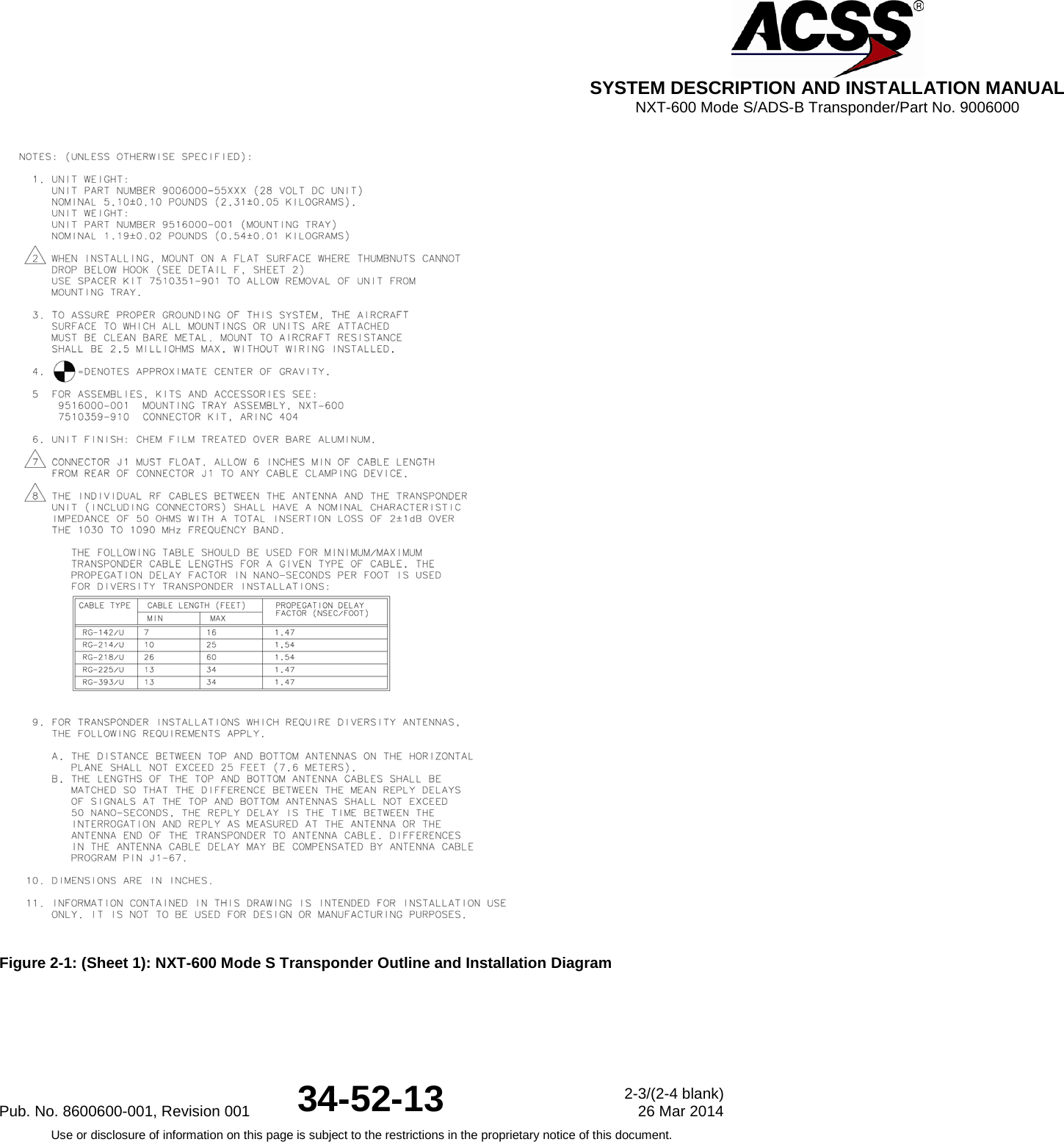
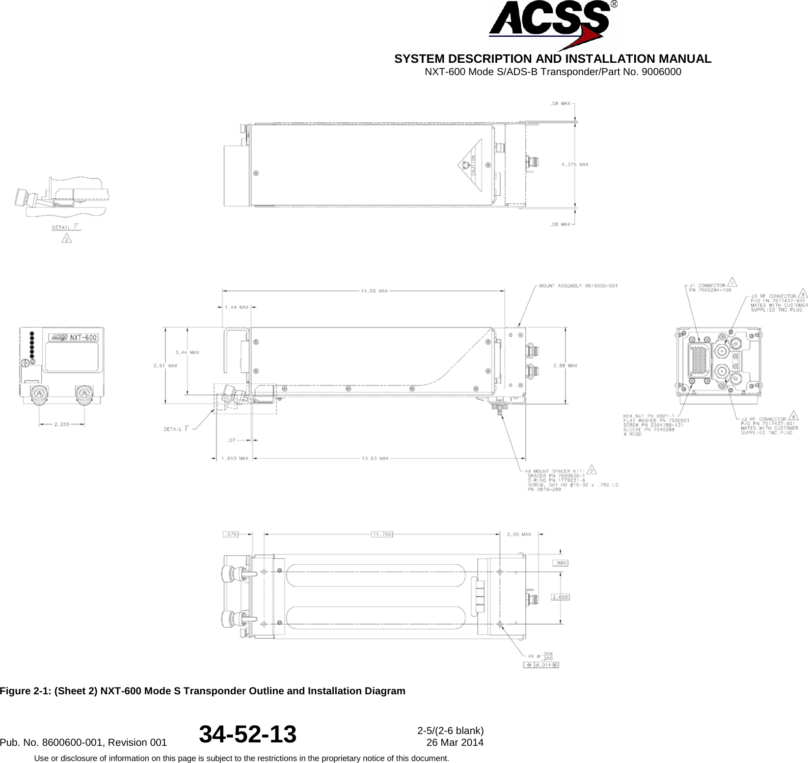
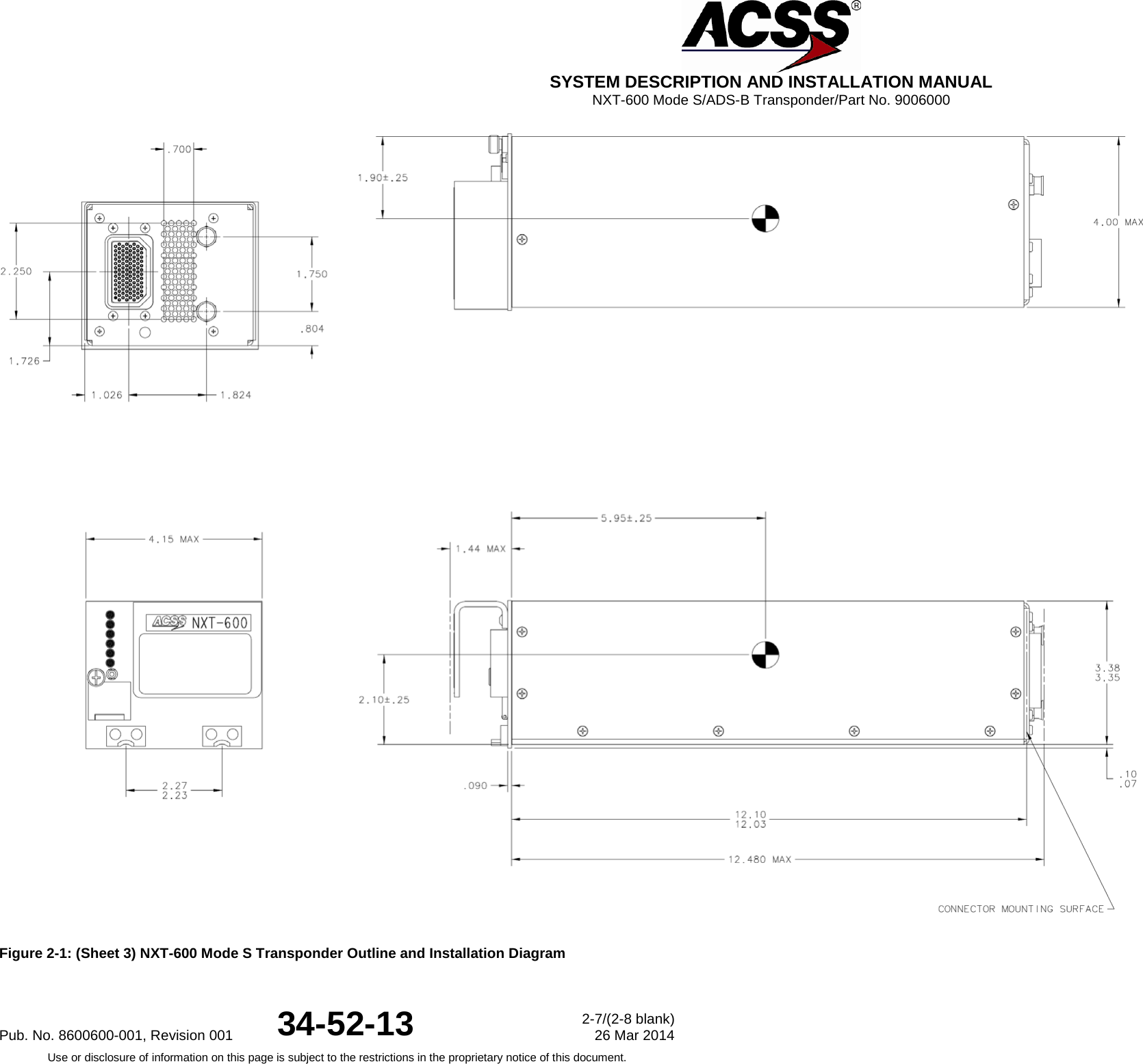
![SYSTEM DESCRIPTION AND INSTALLATION MANUAL NXT-600 Mode S/ADS-B Transponder/Part No. 9006000 E. Line Replaceable Unit (LRU) part numbers and other necessary part numbers contained in this manual should be placed into the aircraft operator's appropriate aircraft Illustrated Parts Catalog (IPC). F. Wiring diagram information contained in this manual should be placed into the aircraft operator's appropriate aircraft Wiring Diagram Manuals. Refer to Figure 2-1 NXT-600 Mode S/ADS-B Transponder Outline and Installation Diagram. G. The transponder is considered an on-condition unit and no additional maintenance is required other than a check for security and operation at normal inspection intervals. H. If a system component is inoperative, remove unit, secure cables and wiring, collar applicable switches and circuit breakers, and placard them inoperative. Revise equipment list and weight and balance as applicable prior to flight and make a log book entry that unit was removed (refer to 14 CFR Part 91.213 or the aircraft's Minimum Equipment List [MEL]). I. The transponder system LRUs can be repaired only at a factory-authorized repair center or an appropriately rated 14 CFR Part 145 repair station. J. Once repaired, reinstall the LRU in the aircraft in accordance with the original Form 337 approved data or instructions in this manual. Do a Return to Service test of the system and approve it for return to service with a log book entry in accordance with the requirements specified in 14 CFR Part 43.9. K. Scheduled Maintenance Program tasks to be added to the aircraft operator's appropriate aircraft maintenance program are as follows: (1) Recommended periodic scheduled servicing tasks: none required. (2) Recommended periodic inspections are as follows. ● The NXT-600 Mode S/ADS-B Transponder has tests and inspections that are required by 14 CFR Part 91.413 to be completed every 24 calendar months. ● The ATC antennas used with the NXT-600 Mode S/ADS-B Transponder should be removed and the underlying structure inspected for deterioration and corrosion every 60 months or 12,000 hours, whichever occurs first. (3) Recommended periodic scheduled preventative maintenance tests (tests to determine system condition and/or latent failures). ● The NXT-600 Mode S/ADS-B Transponder is designed to detect its own failures as well as failures external to the transponder itself. This BIT is continuously being executed on a periodic basis. Refer to Section Fault Isolation. ● No formal periodic maintenance is required for the transponder or the control panel other than the 24 calendar month re-certification test required by 14 CFR Part 91.413. L. If there are changes to the Instructions for Continued Airworthiness, the installation manual will be revised accordingly. When document revisions are approved, the ACSS Customer Services extranet website is automatically updated. The extranet site then notifies the affected customers automatically by email, and on next login of the documentation change. This process is documented in ACSS INS-13.8-1, Distributing Publications via the ACSS Customer Services Extranet. Pub. No. 8600600-001, Revision 001 34-52-13 7-5 26 Mar 2014 Use or disclosure of information on this page is subject to the restrictions in the proprietary notice of this document.](https://usermanual.wiki/Aviation-Communications-and-Surveillance-Systems/NXTXPONDER/User-Guide-2377076-Page-153.png)