Axell Wireless DMINI21082019 Repeater User Manual
Axell Wireless Repeater
UserManual.wiki
>
Axell Wireless
>
DMINI21082019 User Manual
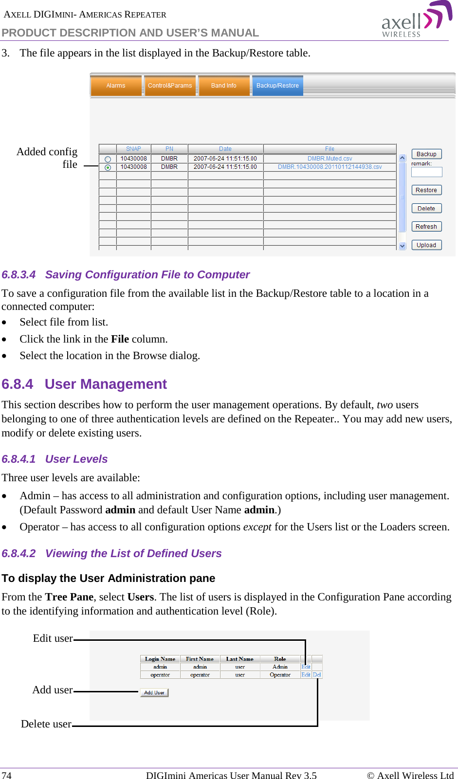
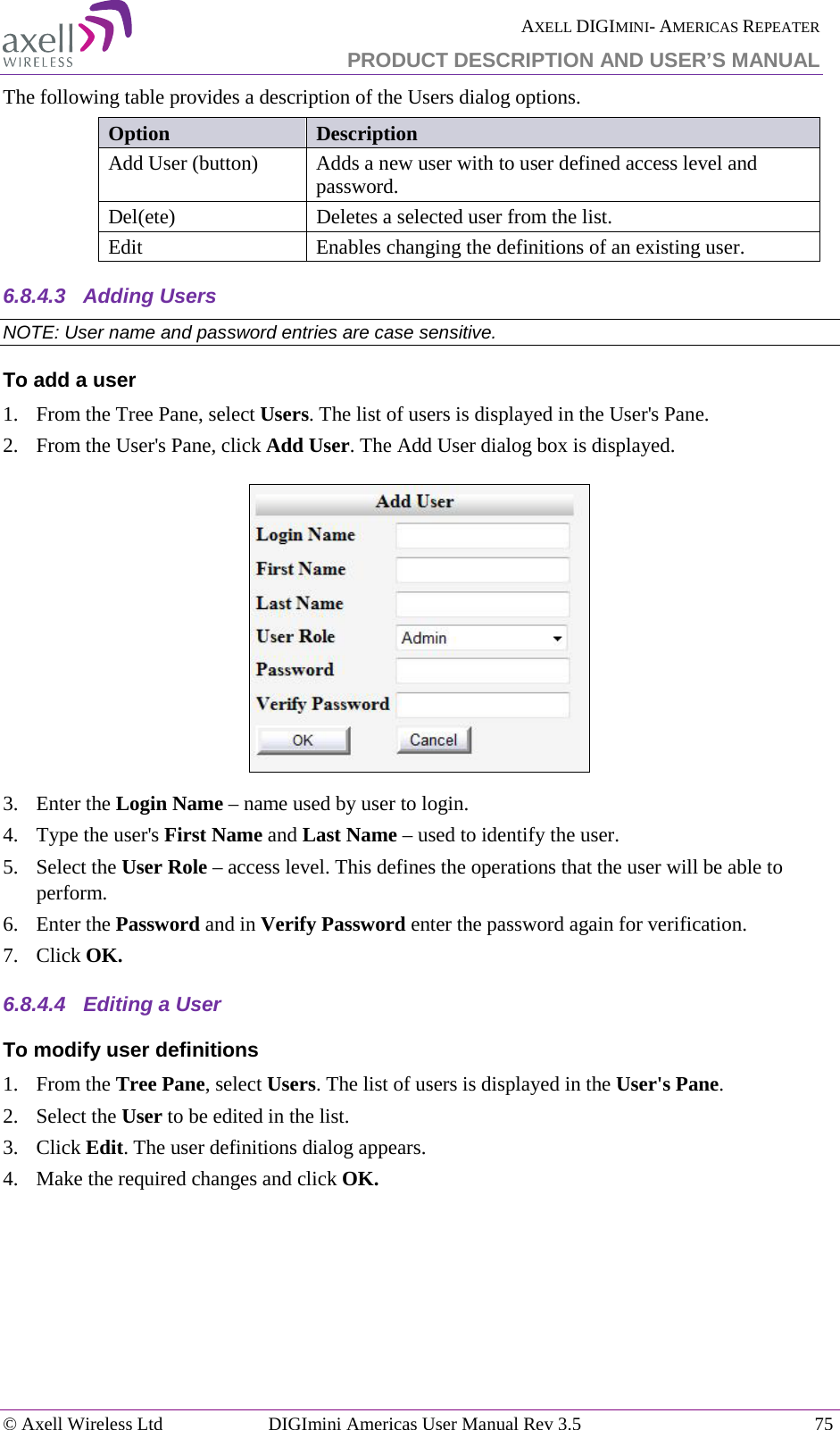
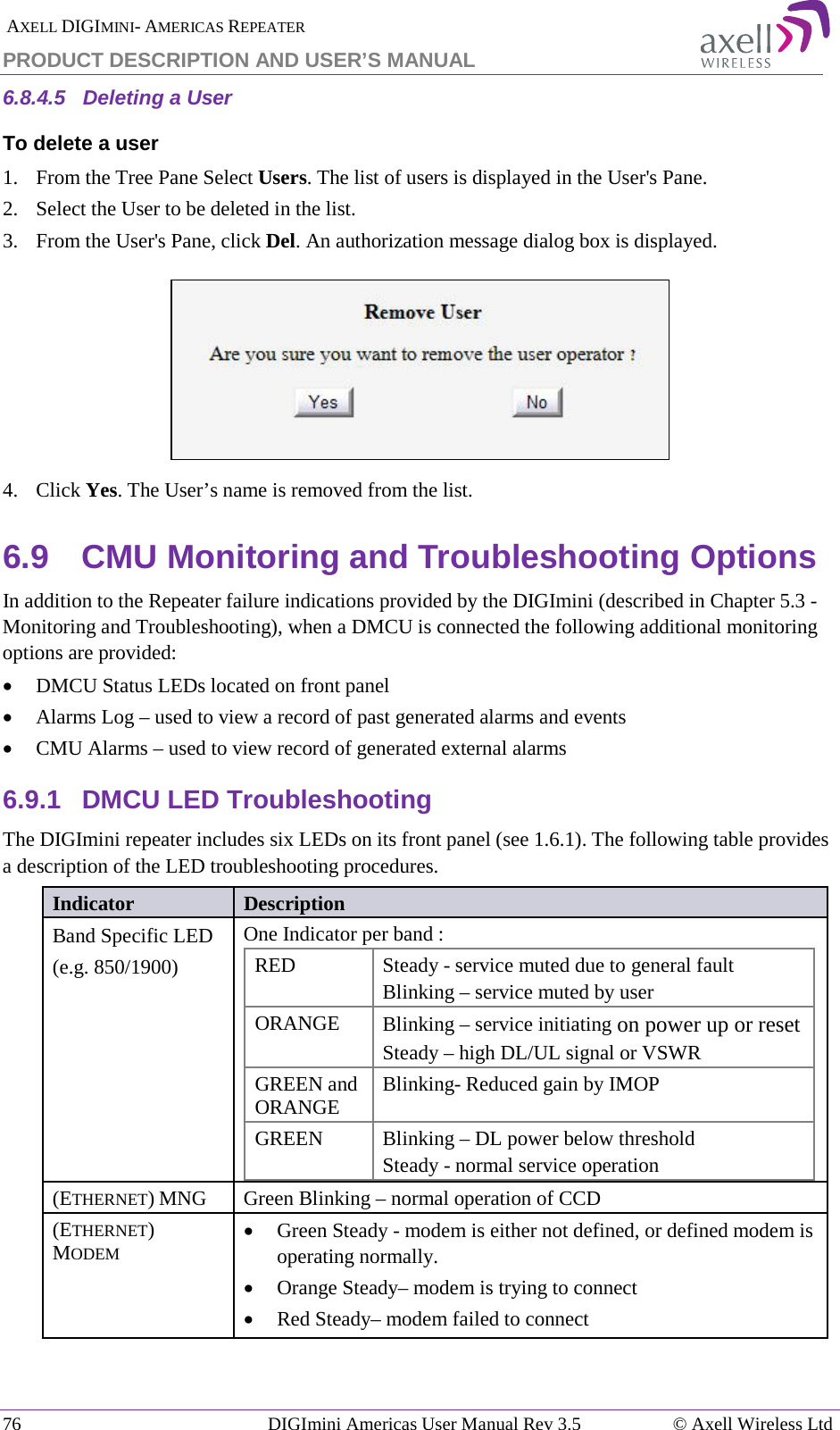
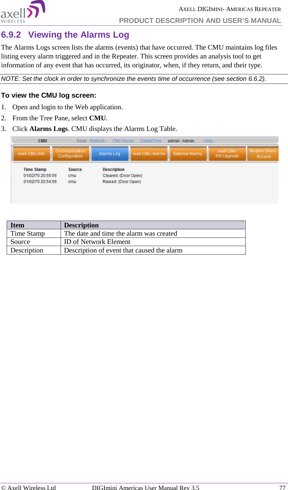
User Manual
Navigation menu
Upload a User Manual
Namespaces
Wiki Guide
HTML
PDF
Info
Views
User Manual
Discussion / Help
Navigation