BAE Systems WINTLAW 802.16 Wideband Transceiver User Manual XX XXXX Exhibit Cover
BAE Systems 802.16 Wideband Transceiver XX XXXX Exhibit Cover
UserManual.wiki
>
BAE Systems
>
WINTLAW User Manual
>
Manual 2 of 2
Contents
1.
Manual 1 of 2
2.
Manual 2 of 2
Manual 2 of 2
Navigation menu
Upload a User Manual
Namespaces
Wiki Guide
HTML
PDF
Info
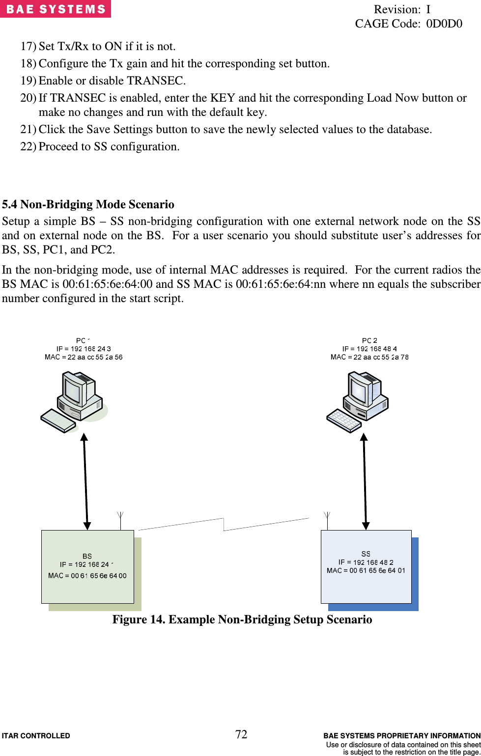
Views
User Manual
Discussion / Help
Navigation