BIOTRONIK SE and KG TACHNT2 Implantable Cardioverter Defibrillator User Manual 417634 B GA Intica ProMRI mul
BIOTRONIK SE & Co. KG Implantable Cardioverter Defibrillator 417634 B GA Intica ProMRI mul
Contents
- 1. 15a_[TACHNT2] UserMan_Inlexa
- 2. 15b_[TACHNT2] UserMan_Ilivia
- 3. 15c_[TACHNT2] UserMan_Intica
15c_[TACHNT2] UserMan_Intica
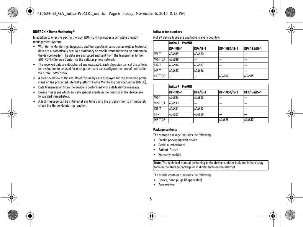
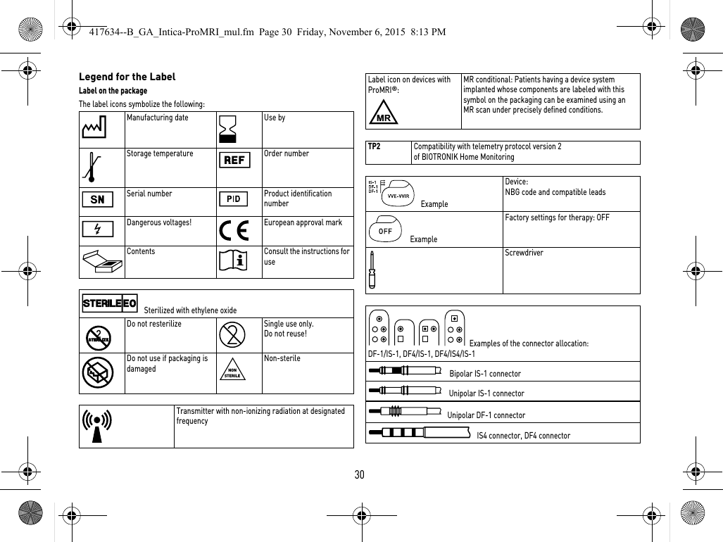
![265 Technical DataMechanical CharacteristicsHousingDevices with header for DF-1 and DF4 connector: Materials in contact with body tissue•Housing: Titanium•Header: epoxy, polysulfone; DF4 seal: silastic•Silicone plugs and blind plugs (if applicable): Silopren or silasticX-ray identificationNKElectrical CharacteristicsStandardsThe specifications are made according to EN 45502-2-2:2008.Measuring conditionsIf not indicated otherwise, all specifications refer to the following conditions:•Ambient temperature: 37ºC ± 2ºC•Pacing/sensing: 500 Ω ±1%•Shock: 50 Ω ± 1% Factory settings•Arrhythmia zones VT1, VT2, VF: OFF•Antibradycardia pacing: OFF•Home Monitoring: OFFTelemetry data for Home Monitoring:•MISC frequencies: 402 – 405 MHz•Maximum power of transmission: < 25 µW (–16 dBm)International radio certificationDevices with BIOTRONIK Home Monitoring are equipped with an antenna for wireless communication.Telemetry information for Canada:This device must neither interfere with meteorological and earth resources technology satellites nor with meteorological stations working in the 400,150 to 406,000 MHZ band, and it must accept any interference received, including interference that may cause undesired operation.•This device will be registered with Industry Canada under the following number:IC: 4708A-TACHNT2The code IC in front of the certification/ registration number only indicates that the technical requirements for Industry Canada are met.•Telemetry information for the USA:This transmitter is authorized by rule under the Medical Device Radiocommunica-tion Service (in part 95 of the FCC Rules) and must not cause harmful interference to stations operating in the 400.150-406.000 MHz band in the Meteorological Aids (i.e., transmitters and receivers used to communicate weather data), the Meteoro-logical Satellite, or the Earth Exploration Satellite Services and must accept inter-ference that may be caused by such stations, including interference that may cause undesired operation. This transmitter shall be used only in accordance with the FCC Rules governing the Medical Device Radiocommunication Service. Analog and digital voice communications are prohibited. Although this transmitter has been approved by the Federal Communications Commission, there is no guarantee that it will not receive interference or that any particular transmission from this trans-mitter will be free from interference.This device will be registered with Federal Communications Commission under the following number:FCC ID: QRITACHNT2Type Lead connector W x H x D in mm Volume [cm3]Mass gVR DF-1 65 x 55 x 11 33 82DF4 65 x 54 x 11 31 81VR DX DF-1 65 x 55 x 11 33 82DR DF-1 65 x 55 x 11 33 82DF4 65 x 56 x 11 32 82HF DF-1 65 x 58.5 x 11 34 83DF4 65 x 56 x 11 33 82HF QP DF-1 65 x 60.5 x 11 36 86DF4 65 x 58.5 x 11 36 87417634--B_GA_Intica-ProMRI_mul.fm Page 26 Friday, November 6, 2015 8:13 PM](https://usermanual.wiki/BIOTRONIK-SE-and-KG/TACHNT2.15c-TACHNT2-UserMan-Intica/User-Guide-2955237-Page-28.png)
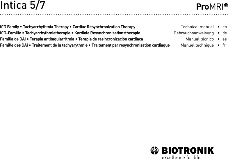
![28Battery DataBattery characteristicsThe following data is provided by the manufacturers: Storage periodThe storage period affects the battery service time.•Devices should be implanted within 19 months between the manufacturing date and the use by date (indicated on the package).•If the ICD is implanted shortly before the use by date, the expected service time may be reduced by up to 17 months.Calculation of service times•The services times have been calculated as follows – in all chambers depending on the device type:—Pulse amplitude: 2.5 V—Pulse width: 0.4 ms—Pacing impedance: 500 Ω—Basic rate: 60 bpm—Home Monitoring: ON, 1 device message each day and 24 IEGM online HD transmissions per year—Diagnostic functions and recordings: permanently set•Capacitor reforming is performed 4 times per year and therefore at least 4 maximum charges for shocks have to be assumed per year even if less than 4 are delivered.Calculation of the number of shocksCalculation of the number of shocks: Service time [in years] x number of shocks per yearManufacturer GREATBATCH, INC. Clarence, NY 14031 LITRONIK Batterietechnologie GmbH01796 Pirna, GermanyBattery type GB 2992 LiS 3410 RRSystem Li/SVO/CFx LiMnO2Battery ID number shown on the programmer36Device type VR, VR DX, DR, HF, HF QPBattery voltage at ERI 2.5 V 2.85 VCharge time at BOS 8 s 8 sCharge time at ERI 10 s 10 sUsable capacity until ERI5 series: VR, VR DX, DR, HF, HF QP7 series: VR, VR DX, DR1390 mAh 1390 mAhUsable capacity until ERI: 7 series: HF, HF QP1600 mAh —Usable capacity until EOS 1730 mAh 1520 mAh417634--B_GA_Intica-ProMRI_mul.fm Page 28 Friday, November 6, 2015 8:13 PM](https://usermanual.wiki/BIOTRONIK-SE-and-KG/TACHNT2.15c-TACHNT2-UserMan-Intica/User-Guide-2955237-Page-30.png)
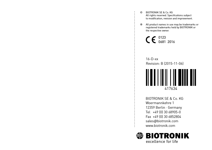
![en • English29Intica 5/7 VR-TService times with GB 2992 or LiS 3410 RR battery: Intica 5/7 VR-T DXService times with GB 2992 or LiS 3410 RR battery: Intica 5/7 DR-TService times with GB 2992 or LiS 3410 RR battery: Intica 5 HF-T (QP)Service times with GB 2992 or LiS 3410 RR battery: Intica 7 HF-T (QP)Service times with battery GB 2992 without multipolar pacing: Service times with battery GB 2992 with multipolar pacing: Pacing Service time [in years] at number of shocks per year481216200%10.3 8.3 7.0 6.0 5.315%10.1 8.1 6.8 5.9 5.250%9.5 7.8 6.6 5.7 5.0100%8.8 7.3 6.2 5.4 4.8Pacing Service time [in years] at number of shocks per year481216200%9.4 7.7 6.5 5.7 5.015%9.2 7.6 6.4 5.6 4.950%8.7 7.2 6.2 5.4 4.8100%8.1 6.8 5.9 5.2 4.6Pacing Service time [in years] at number of shocks per year481216200%9.4 7.7 6.5 5.7 5.015%9.0 7.4 6.3 5.5 4.950%8.1 6.8 5.9 5.2 4.6100%7.1 6.1 5.3 4.7 4.3Pacing Service time [in years] at number of shocks per year4 8 1216200%8.9 7.4 6.3 5.5 4.915%8.3 7.0 6.0 5.2 4.750%7.2 6.1 5.4 4.8 4.3100%6.0 5.3 4.7 4.2 3.9Pacing Service time [in years] at number of shocks per year4 8 1216200%10.1 8.4 7.2 6.3 5.515%9.4 7.9 6.8 6.0 5.350%8.2 7.0 6.1 5.5 4.9100%6.9 6.0 5.4 4.8 4.4Pacing Service time [in years] at number of shocks per year4 8 1216200%10.1 8.4 7.2 6.3 5.515%9.2 7.8 6.7 5.9 5.350%7.7 6.6 5.9 5.2 4.7100%6.2 5.5 5.0 4.5 4.1417634--B_GA_Intica-ProMRI_mul.fm Page 29 Friday, November 6, 2015 8:13 PM](https://usermanual.wiki/BIOTRONIK-SE-and-KG/TACHNT2.15c-TACHNT2-UserMan-Intica/User-Guide-2955237-Page-31.png)