BROWAN COMMUNICATIONS 1254XW Dual Radio 802.11a/n+b/g/n Indoor Access Point User Manual BW1254 UG EN FCC v1 0
BROWAN COMMUNICATIONS Co., Ltd. Dual Radio 802.11a/n+b/g/n Indoor Access Point BW1254 UG EN FCC v1 0
UserManual.wiki
>
BROWAN COMMUNICATIONS
>
1254XW User Manual
>
manual
Contents
1.
manual
2.
Manual
manual
Navigation menu
Upload a User Manual
Namespaces
Wiki Guide
HTML
PDF
Info
Views
User Manual
Discussion / Help
Navigation
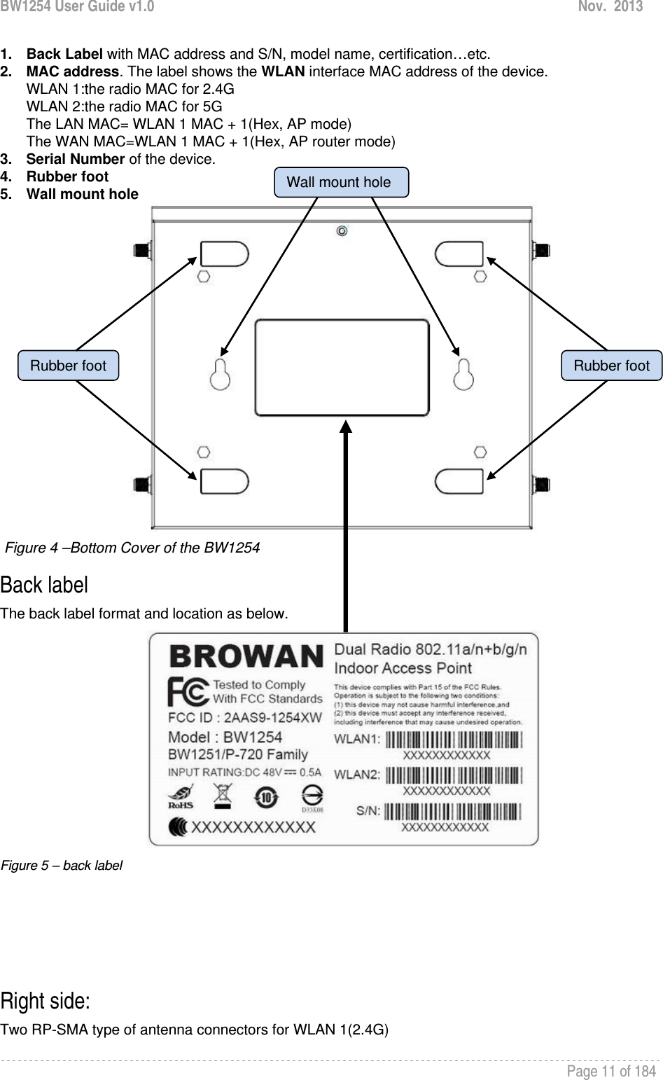
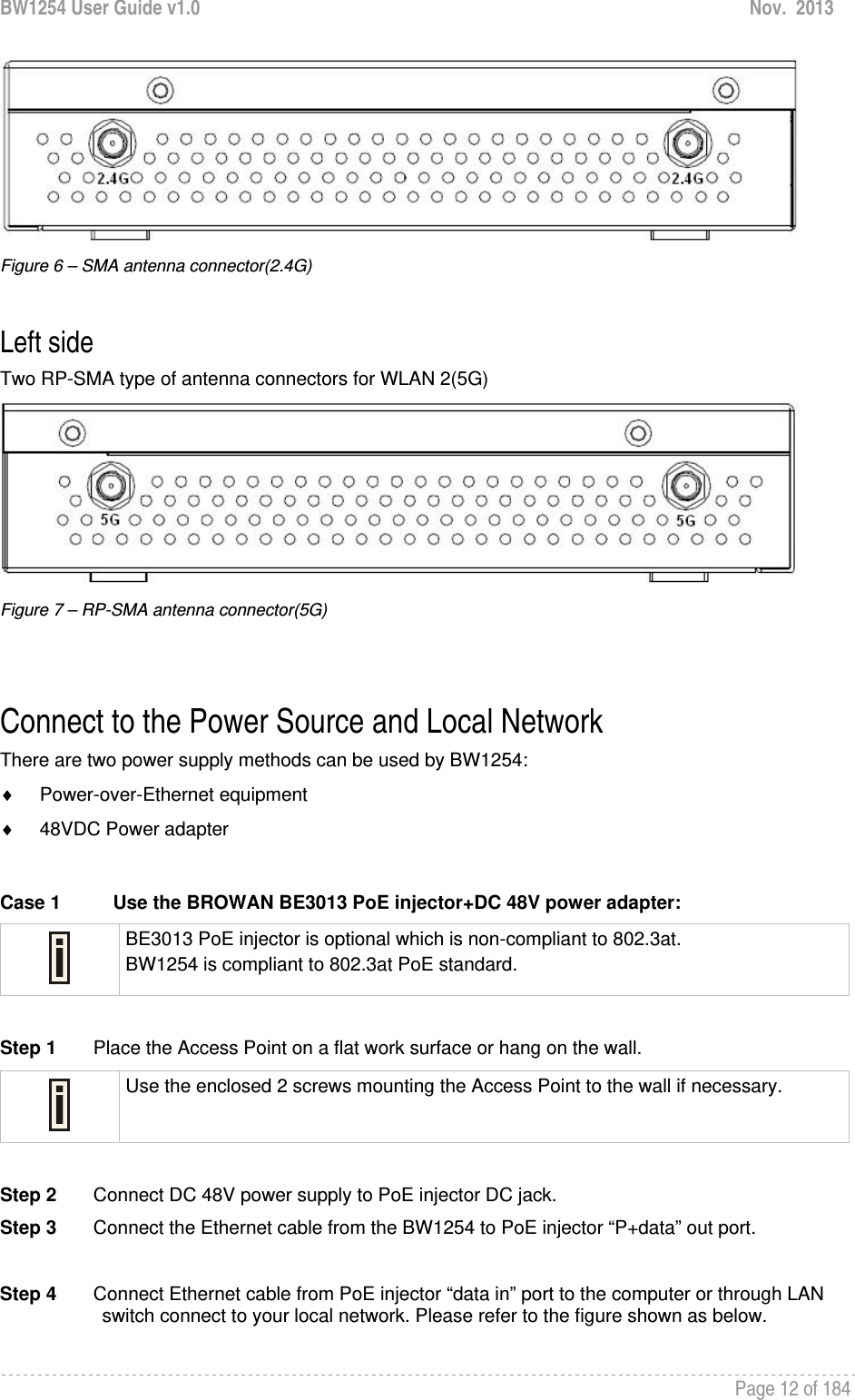
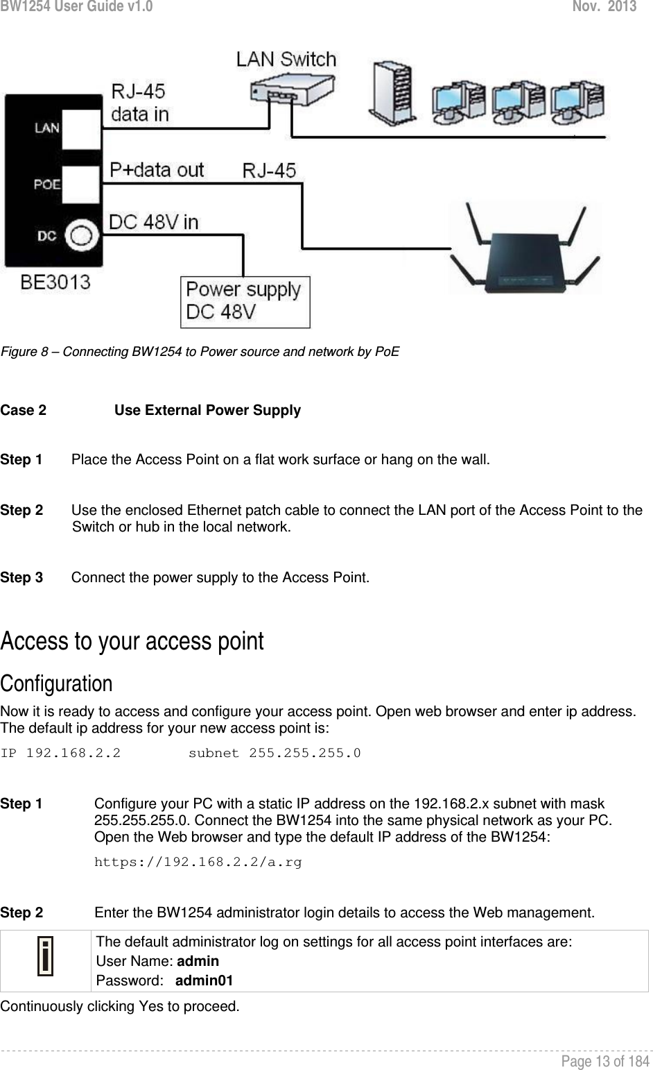
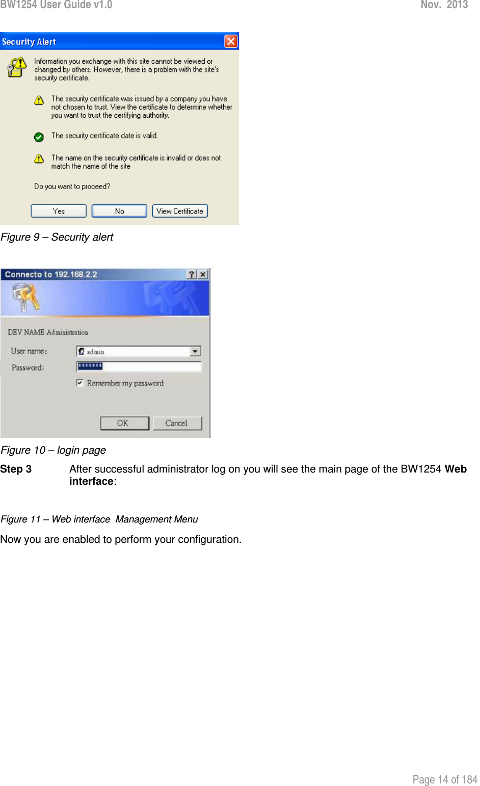
![BW1254 User Guide v1.0 Nov. 2013 Page 6 of 184 Purpose This document provides information and procedures on hardware installation, setup, configuration, and management of the high performance Indoor Access Point BW1254. Prerequisite Skills and Knowledge To use this document effectively, you should have a working knowledge of Local Area Networking (LAN) concepts and wireless Internet access infrastructures. In addition, you should be familiar with the following: Hardware installers should have a working knowledge of basic electronics and mechanical assembly, and should understand related local building codes. Network administrators should have a solid understanding of software installation procedures for network operating systems under Microsoft Windows 95, 98, Millennium, 2000, NT, and Windows XP and general networking operations and troubleshooting knowledge. Conventions Used in this Document The following typographic conventions and symbols are used throughout this document: Very important information. Failure to observe this may result in damage. Important information that should be observed. Additional information that may be helpful but which is not required. bold Menu commands, buttons and input fields are displayed in bold code File names, directory names, form names, and system-generated output such as error messages are displayed in constant-width type <value> Placeholder for certain values, e.g. user inputs [value] Input field format, limitations, and/or restrictions. About this Guide](https://usermanual.wiki/BROWAN-COMMUNICATIONS/1254XW.manual/User-Guide-2191248-Page-7.png)
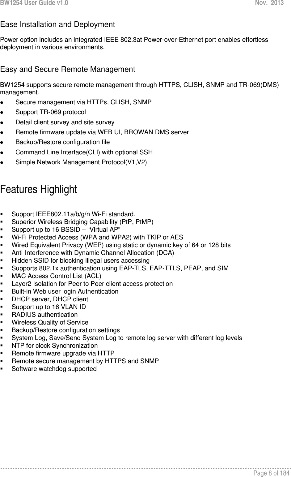
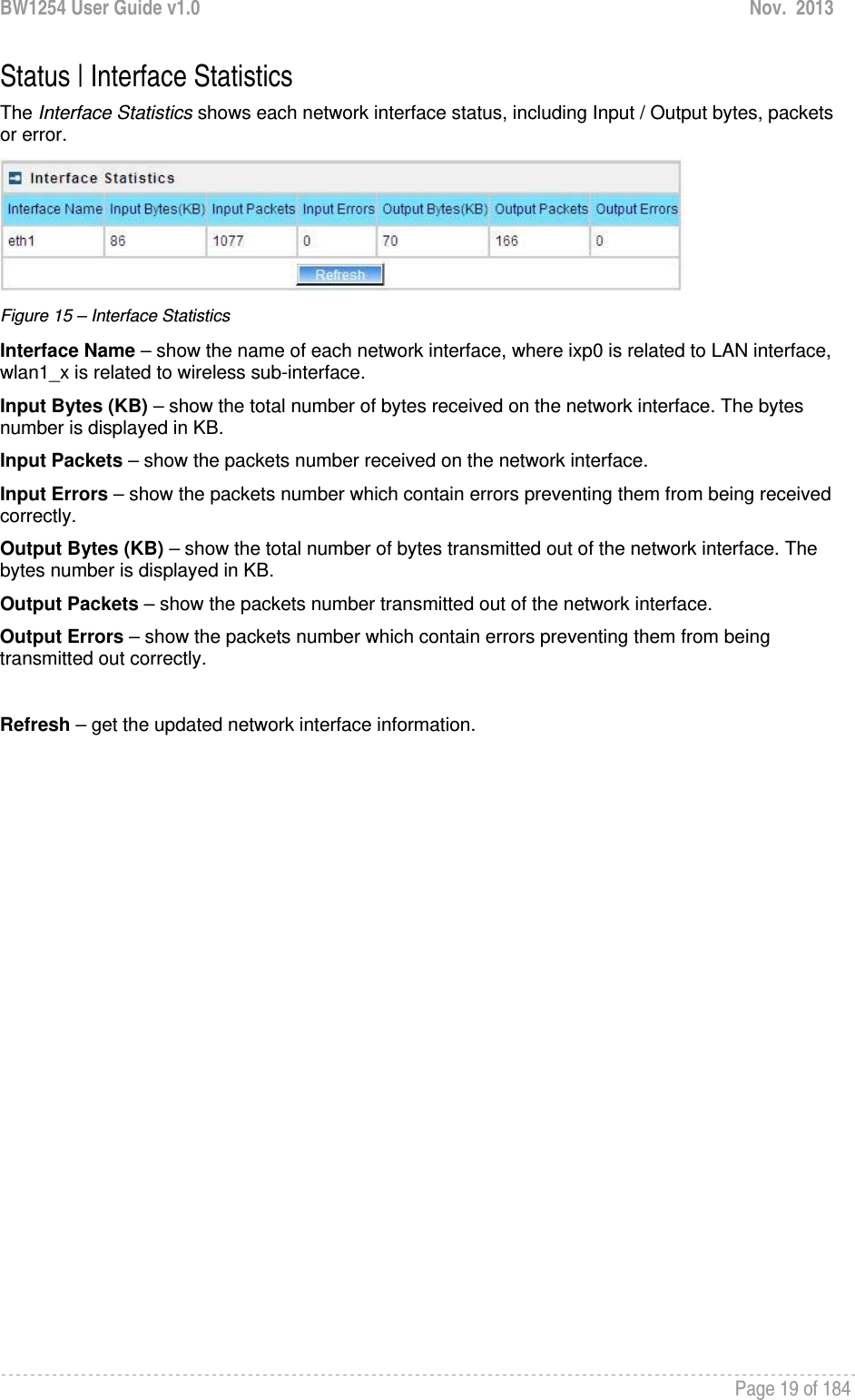
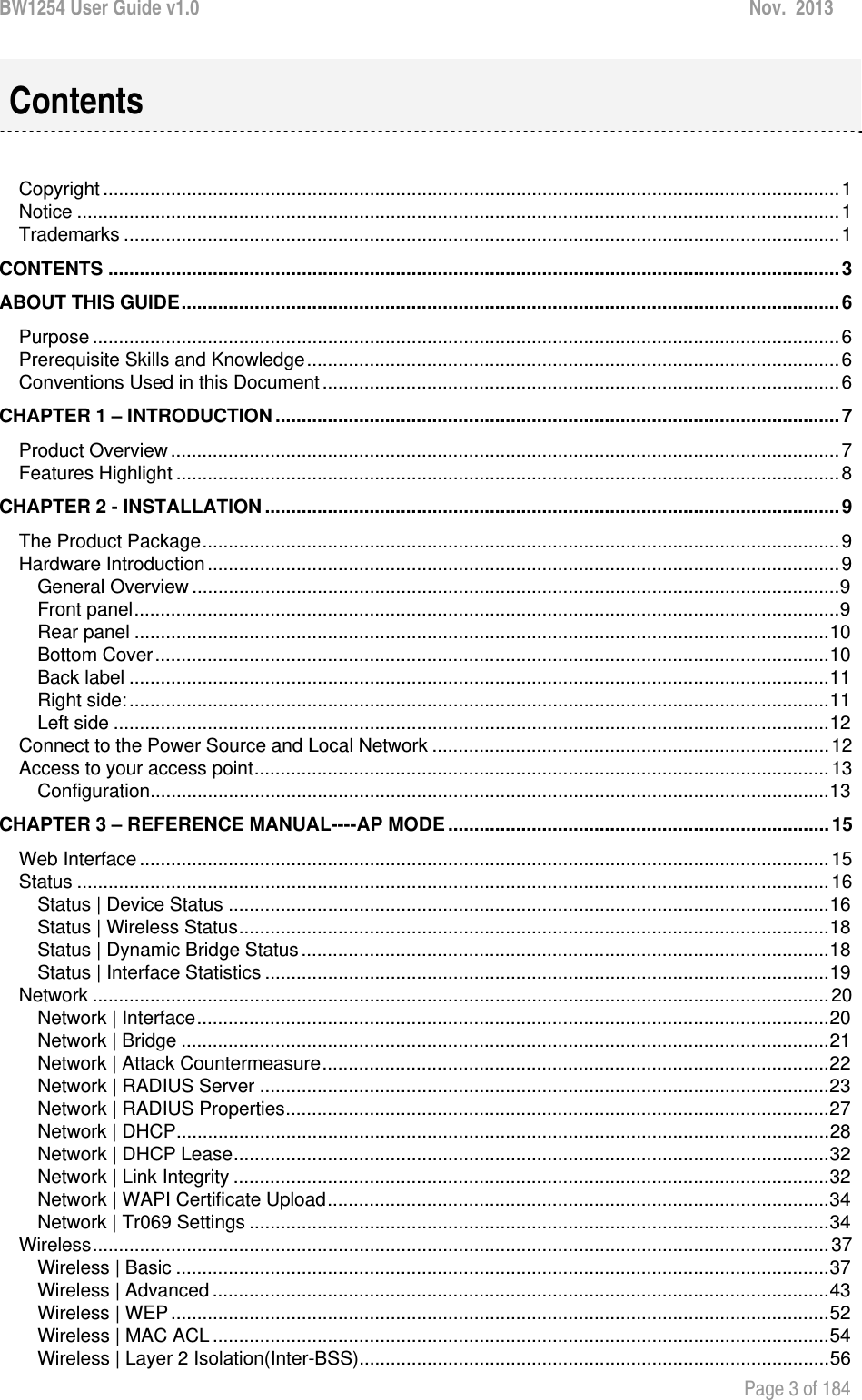
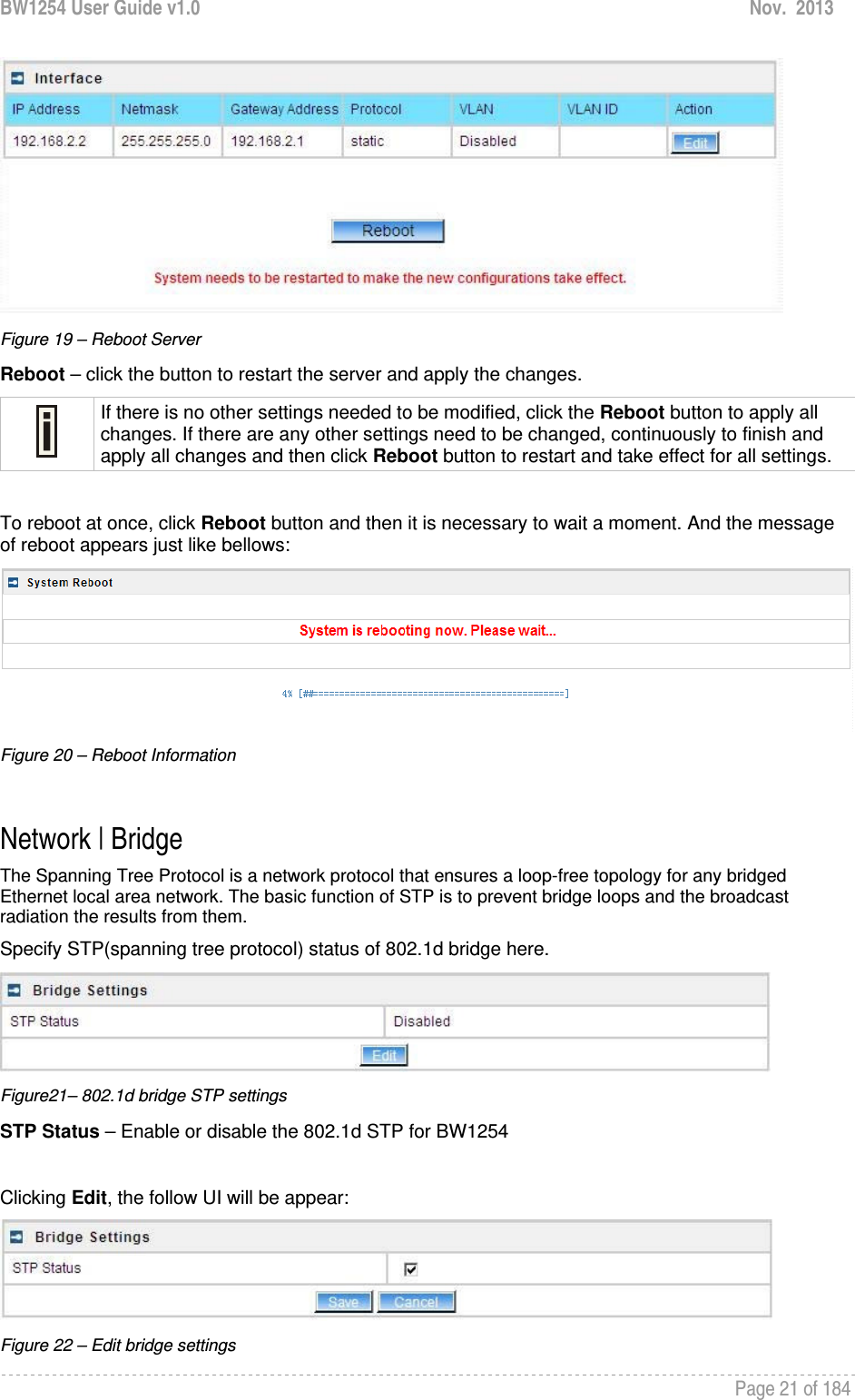
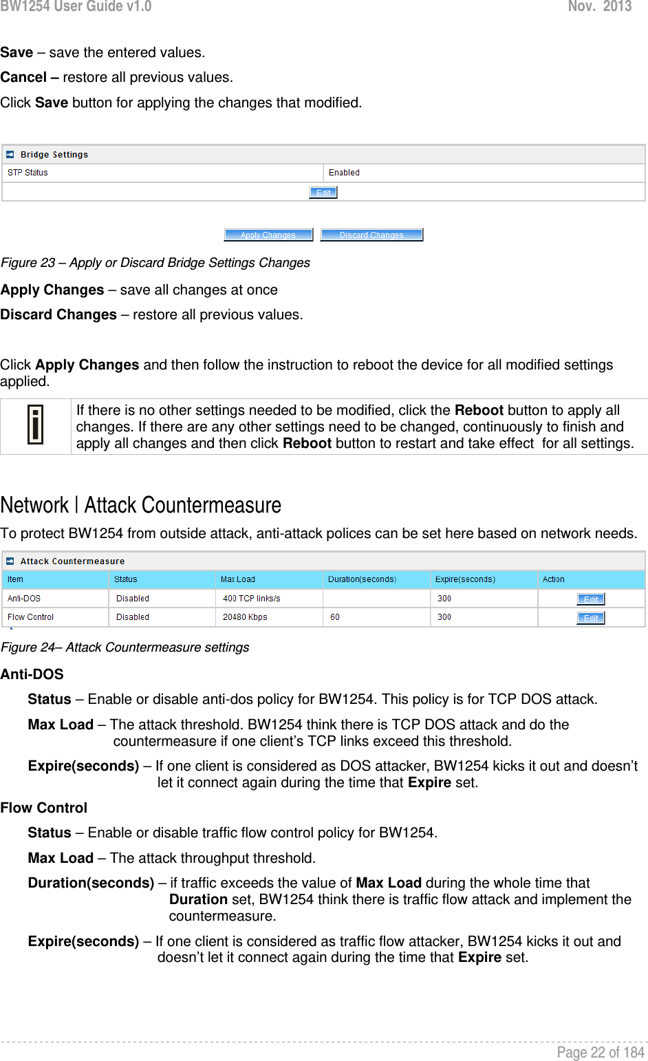
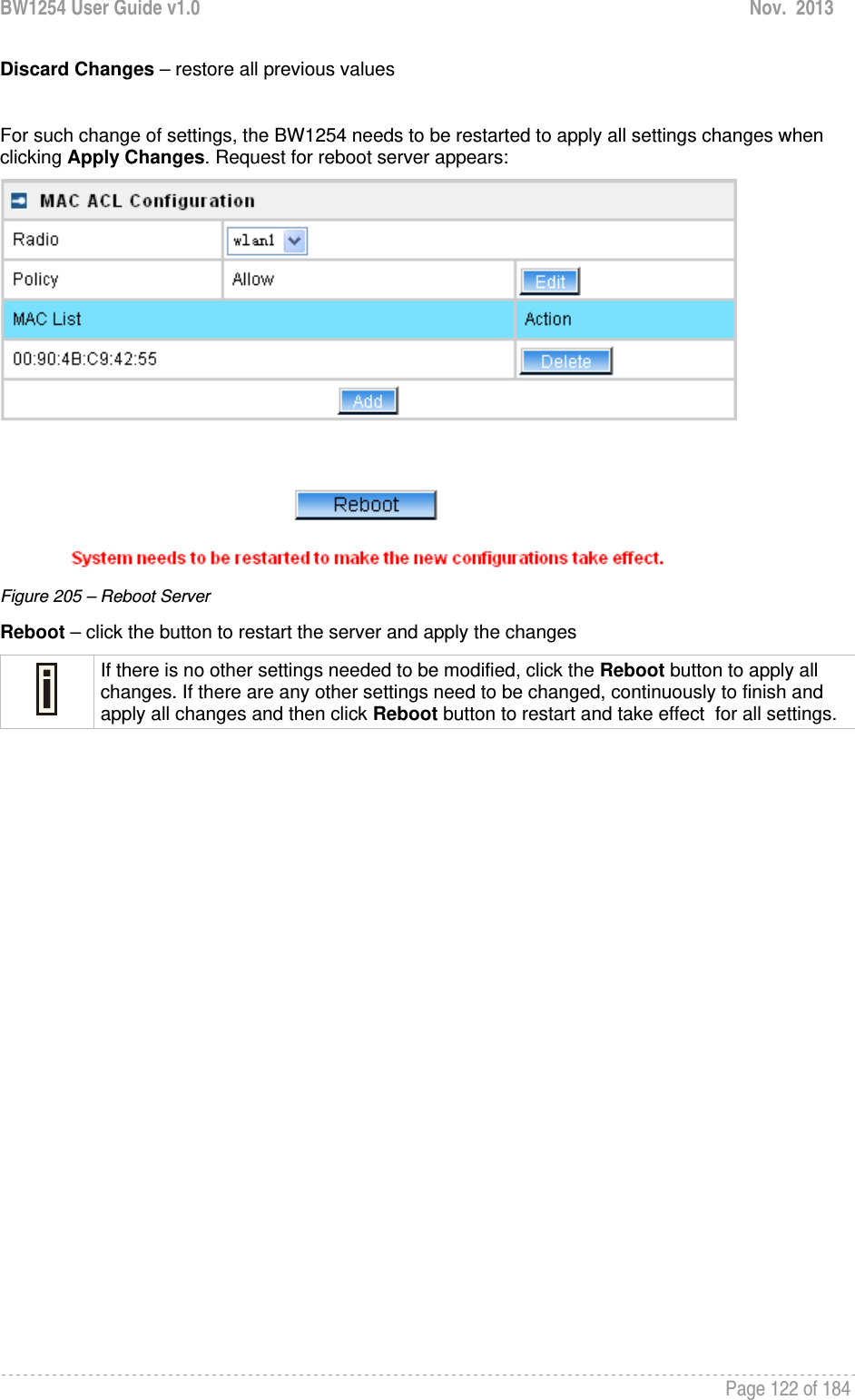
![BW1254 User Guide v1.0 Nov. 2013 Page 20 of 184 Network Network | Interface Figure 16 – Interface Configuration Table To change network interface configuration properties click the Edit button in the Action column. The status can be changed now: Figure 17 – Edit Interface Configuration Settings IP Address – specify new interface IP address [in digits and dots notation, e.g. 192.168.2.2]. Netmask – specify the subnet mask [[0-255].[0-255].[0-255].[0-255]].These numbers are a binary mask of the IP address, which defines IP address order and the number of IP addresses in the subnet Gateway Address – interface gateway. For Bridge type interfaces, the gateway is always the gateway router Protocol – specify static for setting IP address manually and dhcp for getting IP address dynamically acting as DHCP client VLAN – Enable or disable VLAN on LAN (bridge) interface VLAN ID – When enabled VLAN, specify the VLAN ID of it Save – save the entered values. Cancel – restore all previous values. Change status or leave in the default state if no editing is necessary and click the Save button. Figure 18 – Apply or Discard Interface Configuration Changes Apply Changes – save all changes in the interface table at once. Discard Changes – restore all previous values. For such change of settings, the BW1254 needs to be restarted to apply all settings changes when clicking Apply Changes. Request for reboot server appears:](https://usermanual.wiki/BROWAN-COMMUNICATIONS/1254XW.manual/User-Guide-2191248-Page-21.png)
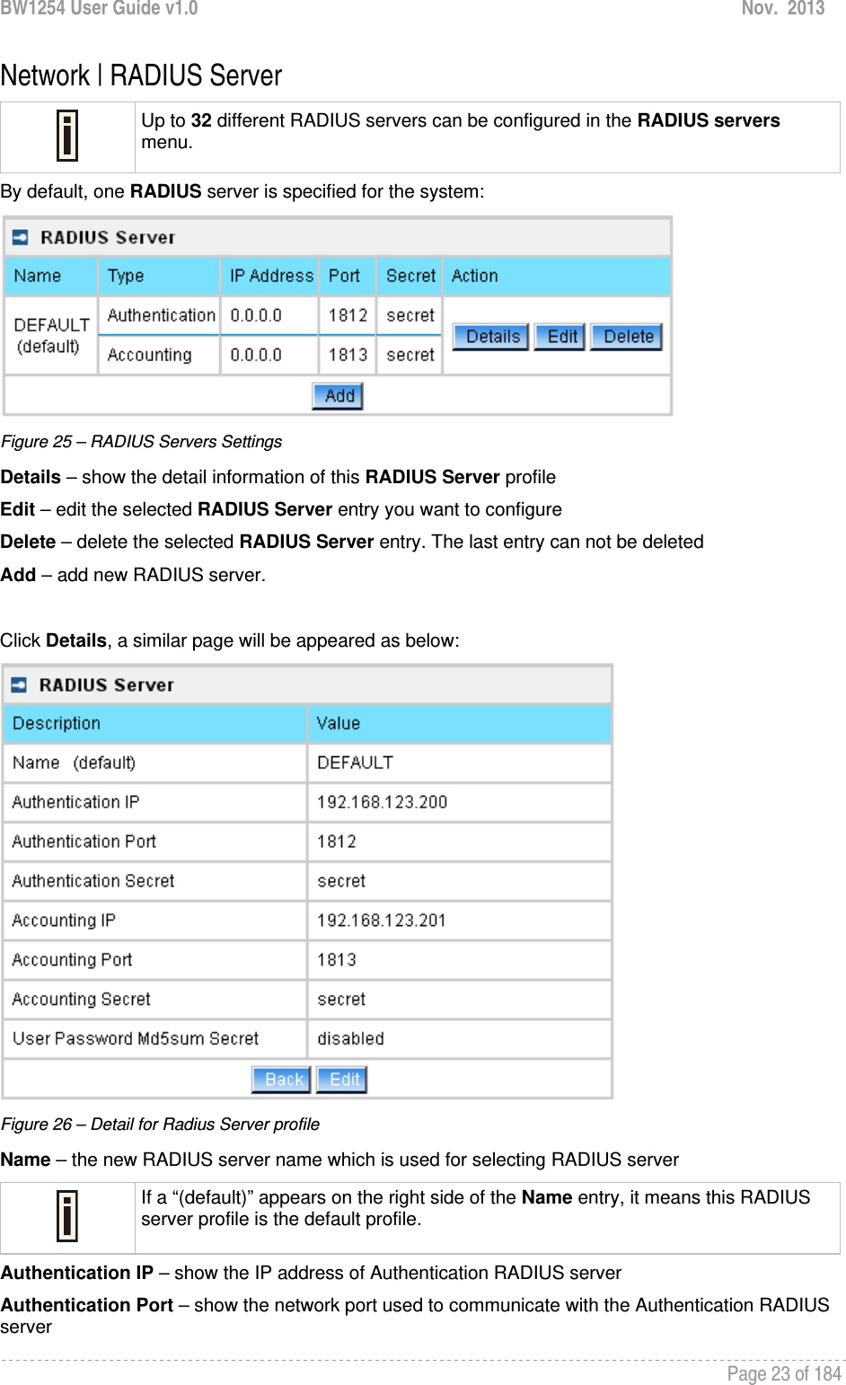
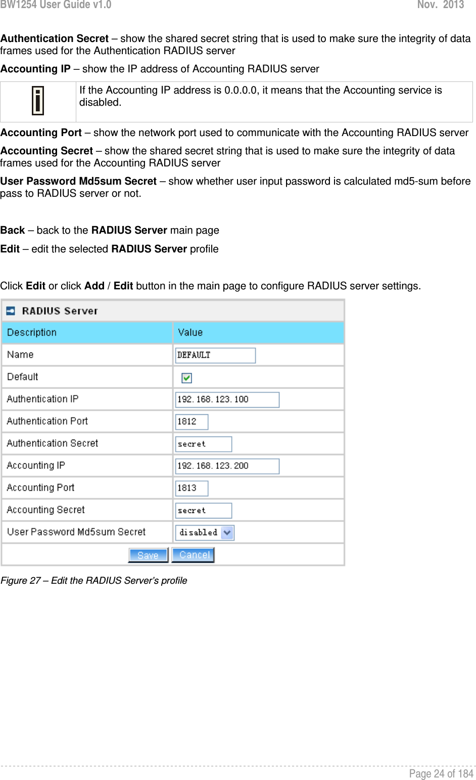
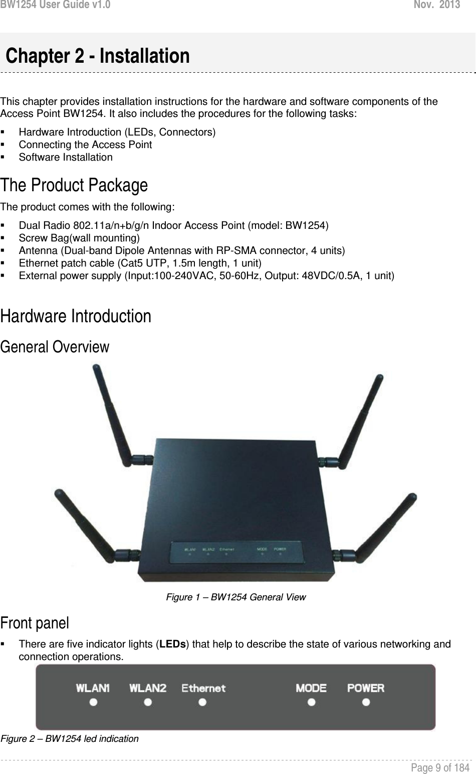
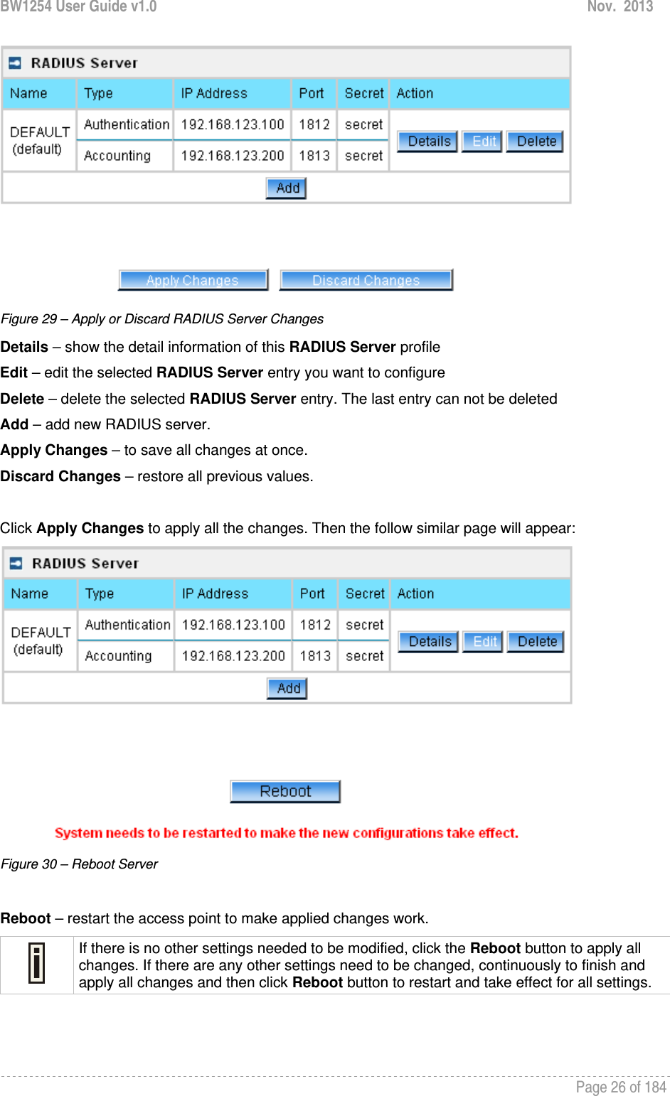
![BW1254 User Guide v1.0 Nov. 2013 Page 25 of 184 Figure 28 – Add a new RADIUS Server's profile Name – specify the new RADIUS server name which is used for selecting RADIUS server Default – specify this RADIUS profile as default or not. When selected, the profile will be used as default Authentication IP – specify the IP address of Authentication RADIUS server [dots and digits] Authentication Port –specify the network port used to communicate with the Authentication RADIUS server [1-65535] Authentication Secret – shared secret string that is used to make sure the integrity of data frames used for the Authentication RADIUS server Accounting IP – specify the IP address of Accounting RADIUS server [dots and digits] Accounting Port –specify the network port used to communicate with the Accounting RADIUS server [1-65535] Accounting Secret – shared secret string that is used to make sure the integrity of data frames used for the Accounting RADIUS server The default port value for authentication is 1812. The default port value for accounting is 1813. The port specified here must be the same with the one on the RADIUS server. User Password Md5sum Secret – if enabled, user input password will be calculated md5-sum before pass to RADIUS server for more security [enabled/disabled] This setting needs RADIUS server implement relevant configurations. Save –save the entered values Cancel – restore all previous values After adding a new RADIUS server or editing an existing one, a page appears similar to the following:](https://usermanual.wiki/BROWAN-COMMUNICATIONS/1254XW.manual/User-Guide-2191248-Page-26.png)
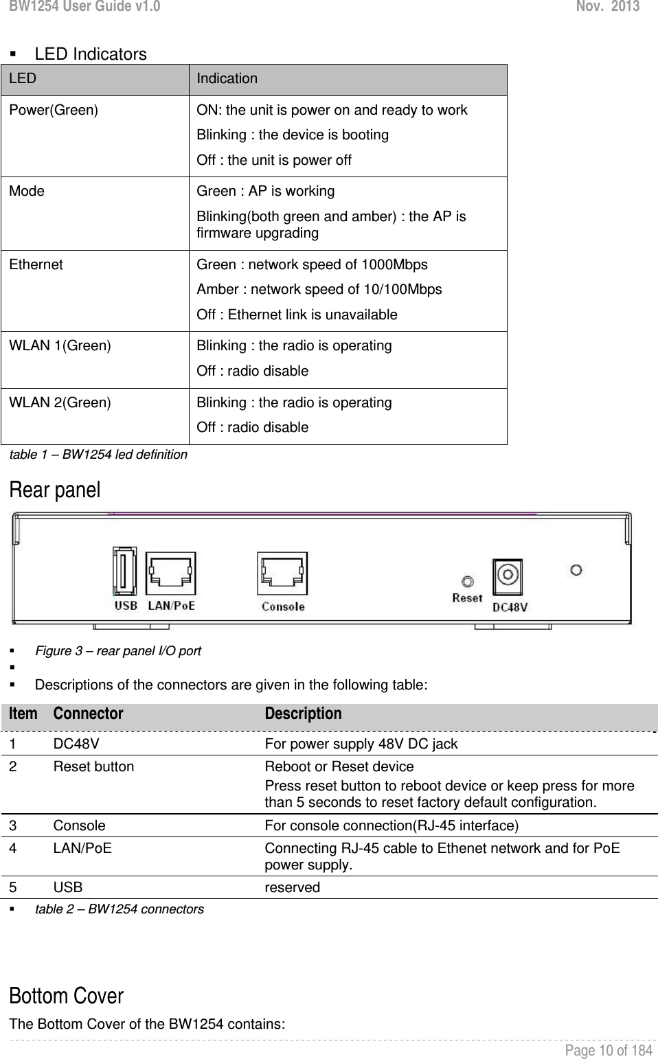
![BW1254 User Guide v1.0 Nov. 2013 Page 27 of 184 Network | RADIUS Properties General RADIUS settings are configured using the RADIUS Properties menu under the network: Figure 31 – RADIUS Properties settings RADIUS Retries – retry count of sending RADIUS packets before giving up [0-99] RADIUS Timeout (seconds) – maximum amount of time before retrying RADIUS packets [1-999] NAS Server ID – name of the RADIUS client User Session Timeout (seconds) – amount of time from the user side (no network carrier) before closing the connect [1-999999999] User Accounting Update Interval (Seconds) – period after which server should update accounting information [60-999999999] User Accounting Update Retry (seconds) – retry time period in which server should try to update accounting information before giving up [60-999999999] User Idle Timeout (seconds) – amount of user inactivity time, before automatically disconnecting user from the network [1-999999999] Each setting in this table can be edited. Select RADIUS setting you need to update, click the edit next to the selected setting and change the value: Figure 32 – edit RADIUS properties](https://usermanual.wiki/BROWAN-COMMUNICATIONS/1254XW.manual/User-Guide-2191248-Page-28.png)
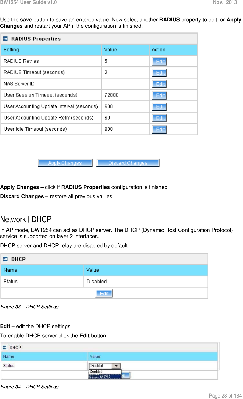
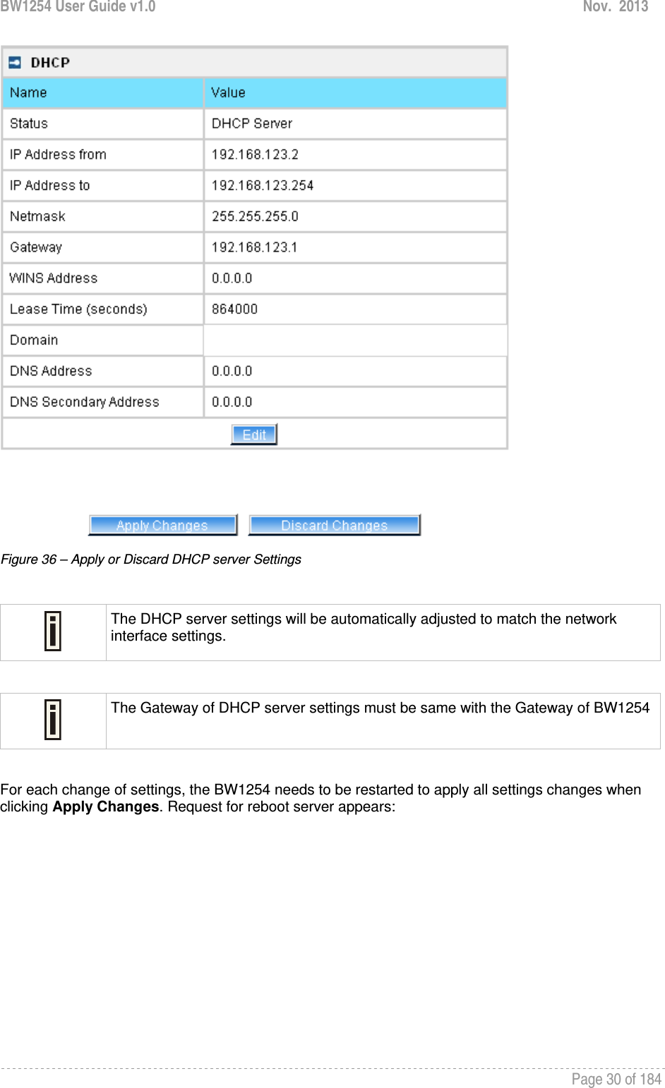
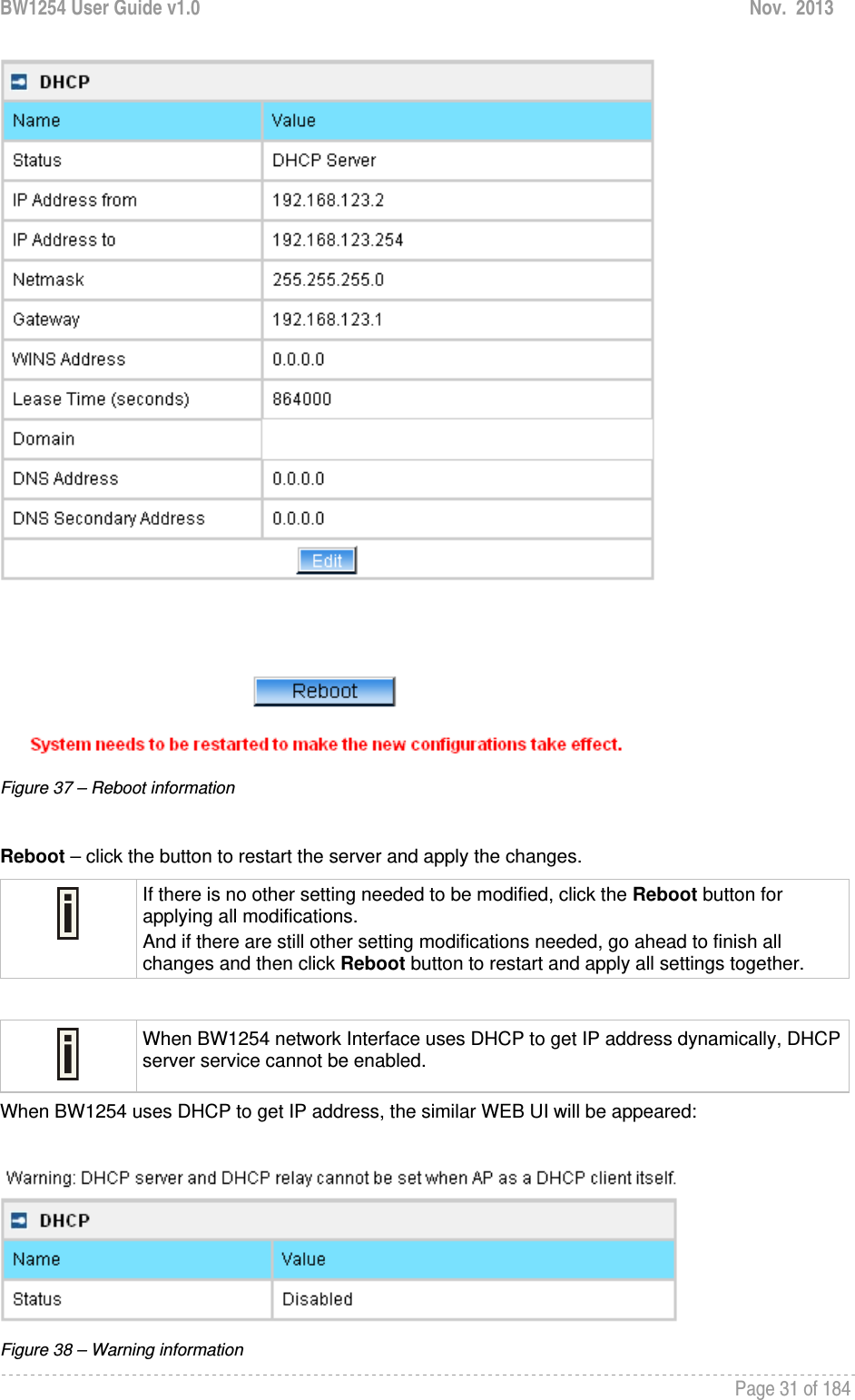
![BW1254 User Guide v1.0 Nov. 2013 Page 29 of 184 Status – select status from the drop-down menu. Disabled – disable the DHCP server service. DHCP Server – enable the DHCP server service. Choose DHCP Server to enable DHCP server service. DHCP Server This DHCP server service enables clients on the LAN to request configuration information, such as IP address, from a server. Settings of the DHCP service can be viewed just like the follow page. Figure 35 – DHCP server Settings By default, DHCP server is disabled. IP Address from / IP Address to – specify the IP address range to be dynamically allocated by the DHCP server. Netmask – enter the netmask for IP pool range. Gateway – enter the gateway IP for wireless clients. WINS Address (Windows Internet Naming Service) – specify server IP address if it is available on the network [dots and digits]. Lease Time – specify the IP address lease interval in seconds [1-1000000]. Domain – specify the DHCP domain name [optional, 1-128 sting]. DNS address – specify the DNS server’s IP address [in digits and dots notation]. DNS secondary address – specify the secondary DNS server’s IP address [in digits and dots notation]. Change status or leave in the default state if no editing is necessary and click the Save button.](https://usermanual.wiki/BROWAN-COMMUNICATIONS/1254XW.manual/User-Guide-2191248-Page-30.png)
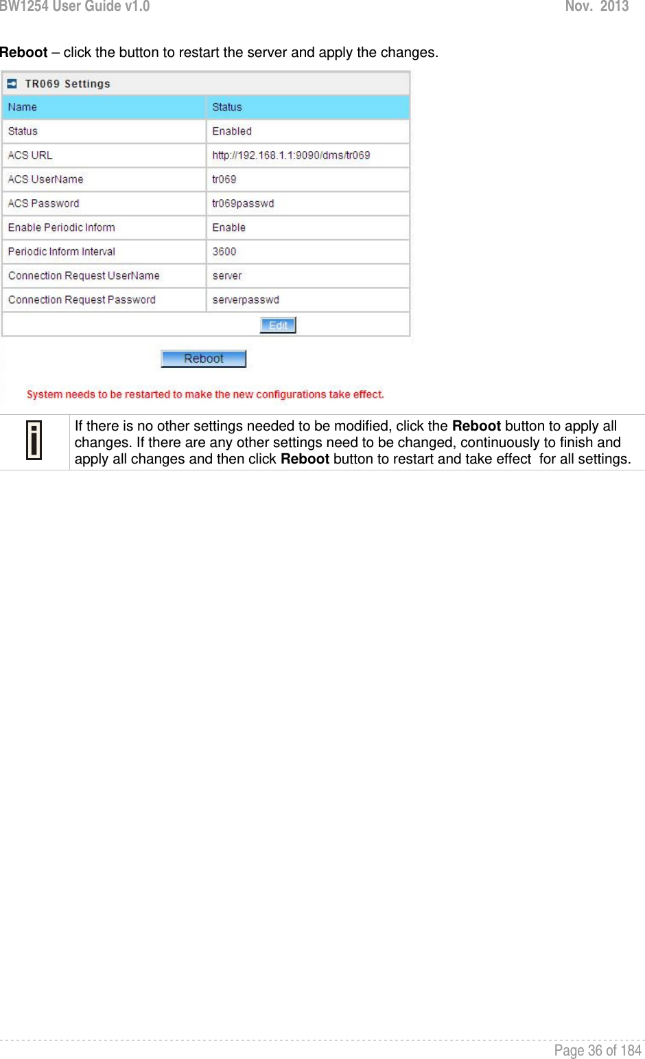
![BW1254 User Guide v1.0 Nov. 2013 Page 35 of 184 Figure 46 – edit TR-069 settings Status – enable or disable TR-069 setting.[enable/disable] ACS URL – enter the ACS server URL. ACS UserName – the user name for AP register to ACS server. ACS UserPassword – the password for AP register to ACS server. Enable Periodic Inform – when AP registered to the ACS server, it will automatically send inform message such as S/N,OUI,manufacturer and product name to the ACS server through TR-069 protocol in a periodic time. Periodic Inform Interval – the inform interval.[in seconds, the value is 720~4294967295] Connection Request UserName – when the ACS pulling a task to AP/CPE such as firmware upgrade/downgrade, AP need the user name to verify the task sending from ACS server. Connection Request Password –when the ACS pulling a task to AP/CPE such as firmware upgrade/downgrade, AP need the password to verify the task sending from ACS server. Contact the ACS server administrator to get the user name and password for Connection Request UserName and Connection Request Password otherwise the AP will not accept the task pulling by ACS server. After enter all field click save and apply changes button to take effect. Figure 47 – save TR-069 settings](https://usermanual.wiki/BROWAN-COMMUNICATIONS/1254XW.manual/User-Guide-2191248-Page-36.png)
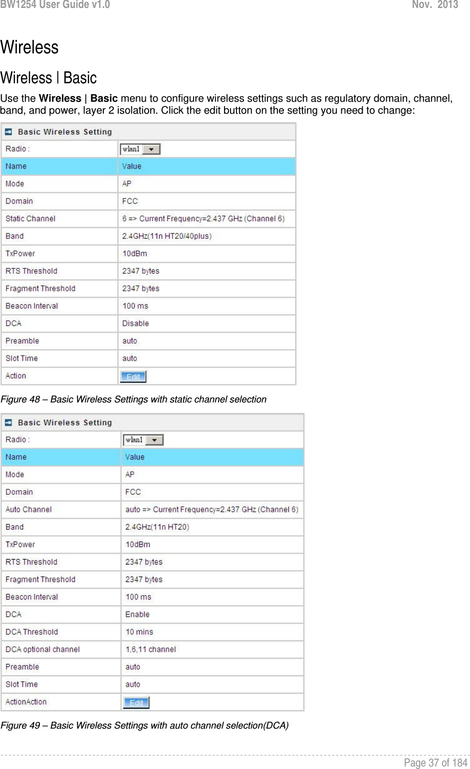
![BW1254 User Guide v1.0 Nov. 2013 Page 38 of 184 Radio – specify which wireless interface of BW1254.[wlan1(2.4G)/wlan2(5G)] Mode – show the radio operation mode. (AP mode or Bridge mode) Domain – show the regulatory domain Static Channel / Auto Channel – show the channel that the access point will use to transmit and receive information If DCA (Dynamic Channel Allocation) is enabled, this will show Auto Channel and its channel number is chosen in auto channel selection. If use static channel selection, this will show Static Channel and its channel number. DCA (Dynamic Channel Allocation) is useful feature to help choose the best channel automatically and reduce interference among many Access Points. Band – show the working bands on which the radio is working. wlan1:four bands listed: 2.4GHz(11g only) , 2.4GHz(11n HT20) , 2.4GHz(11n HT20/40plus), 2.4GHz(11n HT20/40minus) wlan2: four bands listed:5GHz(11a), 5GHz(11n HT20) , 5GHz(11n HT20/40plus), 5GHz(11n HT20/40minus) . By default, the HT20/40 is recommended. Tx Power – show the BW1254 transmission output power (without antenna gain) in dBm. RTS Threshold –the AP sends Request to Send(RTS) frames to a particular receiving station and negotiates the sending of a data frame. After receiving an RTS, the wireless station responds with a Clear to Send(CTS) frame to acknowledge the right to begin transmission. The default value is 2347.[recommend]. Fragment Threshold –It specifies the maximum size for a packet before data is fragmented into multiple packets. If you experience a high packet error rate, you may slightly increase the fragmentation threshold. Setting the fragmentation threshold too low may result in poor network performance. Only minor modifications of this value are recommended. The default value is 2347.[recommend] Beacon Interval –the Beacon Interval value indicates the frequency interval of the beacon. A beacon is a packet broadcast by the AP to synchronize the wireless network. DCA – Enable or Disable DCA service. DCA can help to choose the best working channel automatically. And static channel selection will be forbidden if DCA is enabled. DCA(Dynamic Channel Allocation) solution automatically select the optimal operational frequency channel when power up and periodically monitors the environment and adjusts for the best operational frequency channel. DCA threshold – specify the value (in minutes) of DCA threshold. This threshold is been used to judge if there is no wireless users connected during this time. And if yes, BW1254 will monitor the environment and adjust channel for the best operational one. If wireless network environment is stable which means auto channel selection needn’t do frequently, set a big value for DCA threshold to gain a stable wireless users’ connection. If wireless network environment changes continually, frequent auto channel selection is needed. So set a relative small value for DCA threshold to let channel change based on wireless environment.](https://usermanual.wiki/BROWAN-COMMUNICATIONS/1254XW.manual/User-Guide-2191248-Page-39.png)
![BW1254 User Guide v1.0 Nov. 2013 Page 39 of 184 Wireless users’ will be kicked off when DCA is processing (new operational frequency channel takes effect). DCA optional channel – show the channels only in which auto channel selection (DCA) will be processed to reduce interference. Only when DCA is enabled, DCA threshold and DCA optional channel will be shown. Preamble – if your wireless device supports the short preamble and you are having trouble getting it to communicate with other 802.11b devices, make sure that it is set to use the long preamble. Auto: using long preamble when there are clients not supporting short preamble connected , otherwise using short preamble. The default is Auto.[recommend] Short: always using short preamble. Long: always using long preamble. Slot Time – show the slot time policy when working in 2.4GHz band. Auto: using long slot time when there are clients not supporting short slot time connection, otherwise using short slot time. The default is Auto.[recommend] Short: always using short slot time. Long: always using long slot time. To Maximize the compatibility with some 11b clients, set both Preamble and Slot Time to long. Edit – edit the wireless basic settings To change basic wireless setting properties click the Edit button in the Action column. The status can be changed now: Figure 50 – Edit Basic Wireless Settings with static channel selection](https://usermanual.wiki/BROWAN-COMMUNICATIONS/1254XW.manual/User-Guide-2191248-Page-40.png)
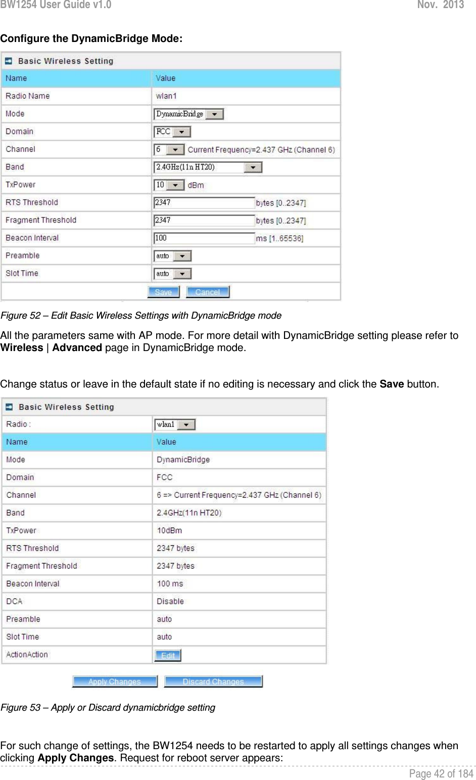
![BW1254 User Guide v1.0 Nov. 2013 Page 40 of 184 Figure 51 – Edit Basic Wireless Settings with DCA enabled Radio Name – specify wireless interface of BW1254 is shown Mode – configure the radio operation mode. [AP mode or Dynamic Bridge mode]. There will be different configuration for the two mode within Wireless | Advanced menu. Please refer to corresponding chapter. Selecting the AP Mode: Domain – select the regulatory domain. Channel – select the channel that the access point will use to transmit and receive information. If one channel is defined, it acts as default channel. Channels list will vary depending on selected regulatory domain and selected band. If you wish to operate more than one access point in overlapping coverage areas, we recommend at least four channels interval between the chosen channels. For example, for three Access Points in close proximity choose channels 1, 6 and 11 for 11b/g or channels 36, 40 and 64 for 11a. Band – show the working bands on which the radio is working. wlan1:four bands listed: 2.4GHz(11g only) , 2.4GHz(11n HT20) , 2.4GHz(11n HT20/40plus), 2.4GHz(11n HT20/40minus) wlan2: four bands listed:5GHz(11a), 5GHz(11n HT20) , 5GHz(11n HT20/40plus), 5GHz(11n HT20/40minus) . TxPower – the BW1254 transmission output power in dBm. The value of the TxPower varies according to channel and regulatory domain. RTS Threshold – the AP sends Request to Send(RTS) frames to a particular receiving station and negotiates the sending of a data frame. After receiving an RTS, the wireless station responds with a Clear to Send(CTS) frame to acknowledge the right to begin transmission. The default value is 2347.[recommend]](https://usermanual.wiki/BROWAN-COMMUNICATIONS/1254XW.manual/User-Guide-2191248-Page-41.png)
![BW1254 User Guide v1.0 Nov. 2013 Page 41 of 184 Fragment Threshold – It specifies the maximum size for a packet before data is fragmented into multiple packets. If you experience a high packet error rate, you may slightly increase the fragmentation threshold. Setting the fragmentation threshold too low may result in poor network performance. Only minor modifications of this value are recommended. The default value is 2347.[recommend] Beacon Interval – the Beacon Interval value indicates the frequency interval of the beacon. A beacon is a packet broadcast by the AP to synchronize the wireless network. DCA – Enable or Disable DCA service. DCA can help to choose the best working channel automatically. And static channel selection will be forbidden if DCA is enabled. DCA(Dynamic Channel Allocation) solution automatically select the optimal operational frequency channel when power up and periodically monitors the environment and adjusts for the best operational frequency channel. DCA threshold – specify the value (in minutes) of DCA threshold. This threshold is been used to judge if there is no wireless users connected during this time. And if yes, BW1254 will monitor the environment and adjust channel for the best operational one. If wireless network environment is stable which means auto channel selection needn’t do frequently, set a big value for DCA threshold to gain a stable wireless users’ connection. If wireless network environment changes continually, frequent auto channel selection is needed. So set a relative small value for DCA threshold to let channel change based on wireless environment. Wireless users’ will be kicked off when DCA is processing (new operational frequency channel takes effect). DCA optional channel – specify the channels only in which auto channel selection (DCA) will choose for reducing interference reference. Only when DCA is enabled, DCA threshold and DCA optional channel will be shown. Preamble – if your wireless device supports the short preamble and you are having trouble getting it to communicate with other 802.11b devices, make sure that it is set to use the long preamble. Auto: using long preamble when there are clients not supporting short preamble connected , otherwise using short preamble. The default is Auto.[recommend] Short: always using short preamble. Long: always using long preamble. Slot Time – specify the slot time policy when working in 2.4GHz band. Auto: using long slot time when there are clients not supporting short slot time connected in, otherwise using short slot time. The default is Auto.[recommend] Short: always using short slot time. Long: always using long slot time. To Maximize the compatibility with some 11b clients, set both Preamble and Slot Time to long.](https://usermanual.wiki/BROWAN-COMMUNICATIONS/1254XW.manual/User-Guide-2191248-Page-42.png)
![BW1254 User Guide v1.0 Nov. 2013 Page 44 of 184 AP Mode If you configure AP mode, the page will be shown as below in Wireless | Advanced menu. Figure 55 – Advanced Wireless Setting (AP Mode) Radio – specify wireless interface to be configured.[wlan1(2.4G/wlan2(5G)] Mode – show the current operation mode of this radio (AP or Bridge mode) Interface – display the interface which corresponding to the SSID. Each Interface maps to a BSSID SSID – SSID name for wireless client searching and associating. Hidden – show the status of Hidden SSID feature[disable/enable] Security – show which security policy is used for this MBSSID entry Current Connect # – show the number of current wireless clients associate to this MBSSID New – create a new MBSSID entry Detail – show the detail information of this MBSSID entry Edit – edit the selected MBSSID entry you want to configure Delete – delete the selected MBSSID entry. When in AP mode, you can not delete the last entry Refresh – rescan the WEB page to get newer information Clicking New or Edit button to configure the SSID parameters. Describe as below:](https://usermanual.wiki/BROWAN-COMMUNICATIONS/1254XW.manual/User-Guide-2191248-Page-45.png)
![BW1254 User Guide v1.0 Nov. 2013 Page 45 of 184 Figure 56 – BSSID Setting -1 Radio – show the wireless interface is being configured. Interface – show the current sub-interface. Mode – show the operation mode of current radio. SSID – a unique ID for your wireless network. It is case sensitive and must not exceed 32 characters. The SSID is important for clients when connecting to the access point. Need Hidden SSID – when enabled, the SSID of this Interface is invisible in the networks list while scanning the available networks for wireless client (SSID is not broadcasted with its Beacons). When disabled, the AP’s SSID is visible in the available network list [enabled/disabled]. By default the Hidden SSID is disabled SSID status – activated or deactivated the SSID. The default is activated SSID[check box]. Disable 11b – enable/disable 11b client connection. [check box] to enable the function. Only 11n – only 802.11n client can connected to the SSID. Disassociation low MCS – low MCS client won’t associate to the AP. [check box] to enable it. Max Station Number – define maximum number of associated wireless client to this SSID. By default the number is maximum 127 client can be associated to the AP without check box. Or check box to enable limited client.[1~127] Layer 2 Isolation – Specify the layer 2 isolation policy. Enable Intra-BSS Layer 2 Isolation – when enabled, the clients that connect in this same BSS can’t visit each other. By default the intra-BSS layer 2 isolation is disabled. Intra-BSS layer2 isolation – which enable or disable client isolation under same SSID.Inter-BSS layer2 isolation – which enable or disable client isolation between different SSID. Please go to Wireless | Layer 2 Isolation(Inter-BSS) menu to configure inter-BSS layer 2 Isolation. Full layer 2 isolation need to set both intra-BSS and inter-BSS layer 2 isolation in the AP mode. Bandwidth – enable/disable upstream/downstream bandwidth control per SSID.](https://usermanual.wiki/BROWAN-COMMUNICATIONS/1254XW.manual/User-Guide-2191248-Page-46.png)
![BW1254 User Guide v1.0 Nov. 2013 Page 46 of 184 Download bandwidth – specified the maximum downstream in Mbps controlled by the SSID. Upload bandwidth – specify the maximum upstream in Mbps controlled by the SSID. Figure 57 – Multiple BSSID Setting -2 VLAN – specify VLAN policy Enable VLAN – when enabled, the outgoing packets from this SSID device will be tagged with VLAN ID and 802.1p tag. VLAN ID – configure VLAN ID for each Multiple SSID devices. Valid numbers are from 1 to 4094 802.1p Tag – configure 802.1p Tag for remote APC’s or Router’s QoS uses. Eight levels selective, Background(1), Spare(2), Best Effort(0), Excellent Effort(3), Controlled Load(4), Interactive Video(5), Interactive Voice(6), Network Contro(7) VLAN ID and 802.1p tag must cooperate with remote Router or APC. Interface priority – specify the traffic priority for this SSID interface, which is implemented according to 802.11e EDCA and makes sure the wireless downlink QoS. This priority is based on SSID, which means different BSSID can have different traffic priority and the traffic of the same SSID has the same priority This traffic priority only makes sure the priority of downlink (from AP to wireless client). 8 levels priorities are supplied. 1, 2, 0, 3, 4, 5, 6, 7 is from lowest priority to highest priority. And if no special QoS is needed, leave priority to default (0). 0 means Best Effort priority. WMM –BW1254 support WMM wireless clients and implement WMM QoS with the WMM clients. [enable] ESS in Tunnel – Settings for ESS in tunnel. When enabled, BW1254 setup tunnel with remote AC for passing through layer3 network. Remote Server IP – IP address of remote AC product that setup tunnel with BW1254](https://usermanual.wiki/BROWAN-COMMUNICATIONS/1254XW.manual/User-Guide-2191248-Page-47.png)


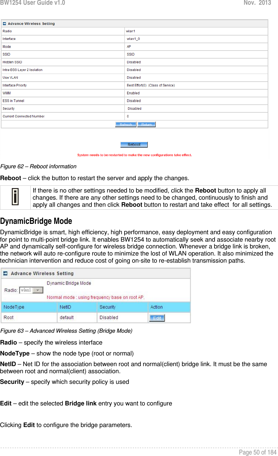
![BW1254 User Guide v1.0 Nov. 2013 Page 49 of 184 Figure 60 – Multiple BSSID Setting – 5 WAPI – WLAN Authentication and Privacy Infrastructure (WAPI) is a Chinese National Standard for wireless LAN(GB15629.11-2003).(Only for China) It needs to upload WAPI certificate. AAA Server Profile – select your RADIUS server profile WAPI-PSK –the encrypt method will be WAPI without RADIUS server Encode – Pre-shared key encode.[HEX/ASCII] Use Pre-Shared key – specify more than 8 characters and less than 64 characters for WPA with pre-shared key encryption Disabled – when selected, you don’t select any security policy Change status or leave in the default state if no editing is necessary and click the Save button. Figure 61 –Apply or Discard the advanced Settings in AP mode For each change of settings, the BW1254 needs to be restarted to apply all settings changes when clicking Apply Changes. Request for reboot server appears:](https://usermanual.wiki/BROWAN-COMMUNICATIONS/1254XW.manual/User-Guide-2191248-Page-50.png)
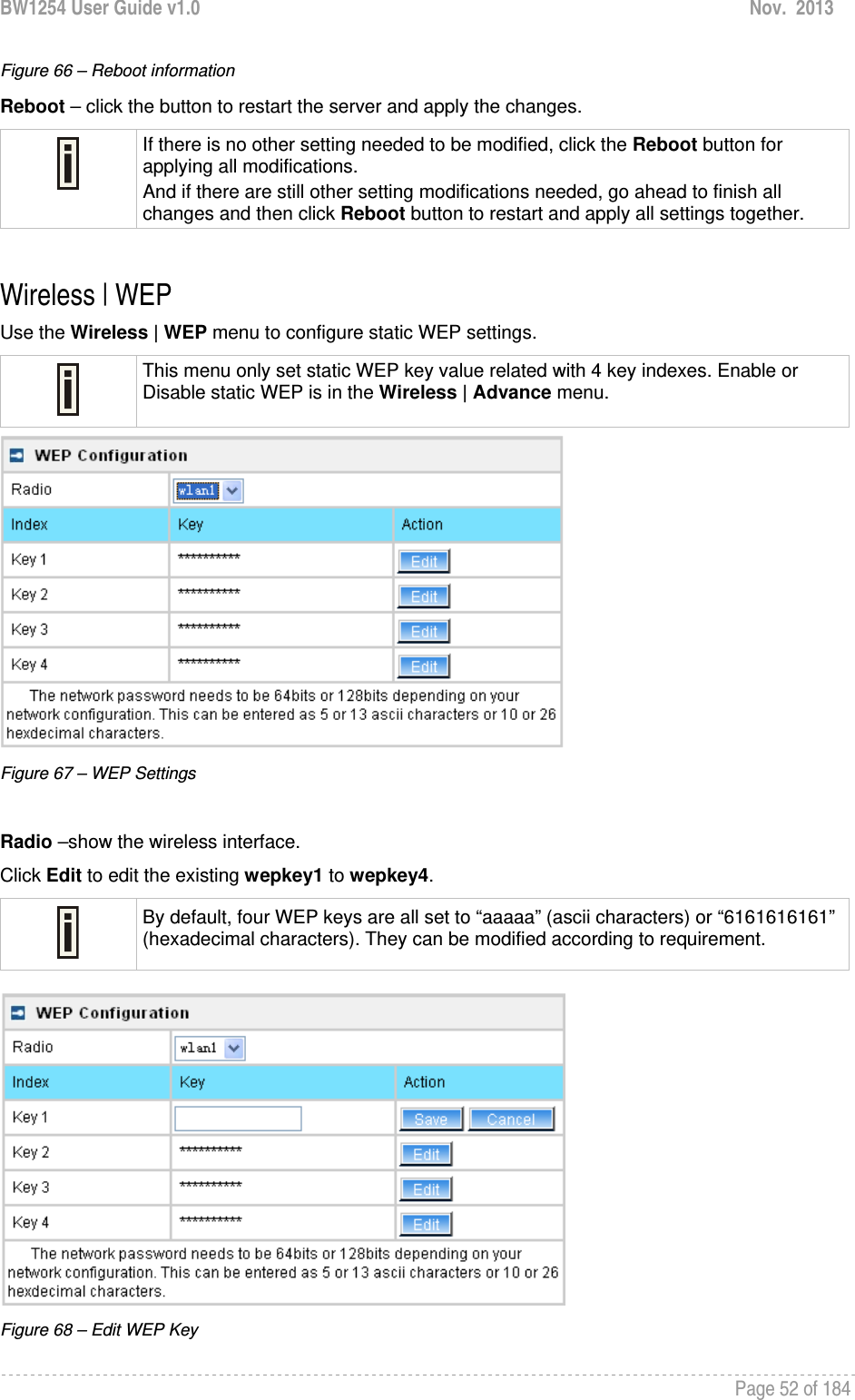
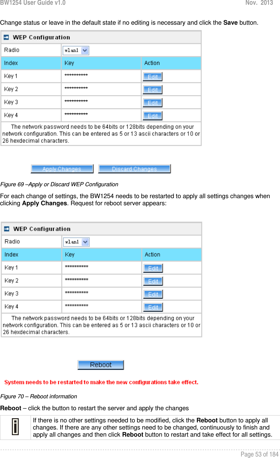
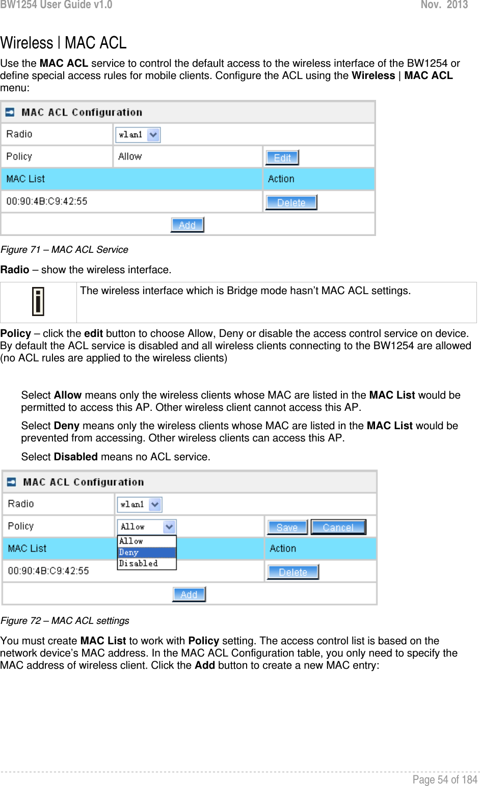
![BW1254 User Guide v1.0 Nov. 2013 Page 51 of 184 Figure 64 – Bridge Link Setting NodeType – determine the AP as Root or client rule. As a root AP, the nearby bridge client will automatically associate to the root AP based on the signal quality. In case a bridge link is broken, the client AP will automatically seek the nearby root AP based on the best signal quality and same NetID to re-build a bridge link. For the client AP the NetID must same with root AP to distinguish which root AP is in the link table. And the frequency channel is determined by the root AP despite the client AP configured. NetID – NetID is a very important element for the dynamicbridge link. The link between root and client AP will based on the same NetID to make the bridge link. Security – specify the security policy of the bridge link. [WPA-PSK (AES)/disable] WPAPSK-AES –specify more than 8 characters and less than 64 characters for WPA with pre-shared key encryption Disable – no data encryption for the bridge link. Click Save button to save the change of settings or Cancel button to discard the change Figure 65 –Apply or Discard the advanced Settings in Bridge mode For each change of settings, the BW1254 needs to be restarted to apply all settings changes when clicking Apply Changes. Request for reboot server appears:](https://usermanual.wiki/BROWAN-COMMUNICATIONS/1254XW.manual/User-Guide-2191248-Page-52.png)
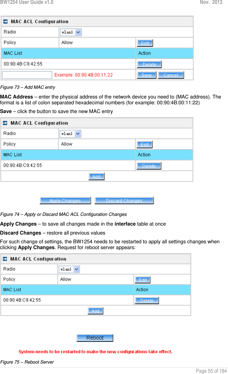
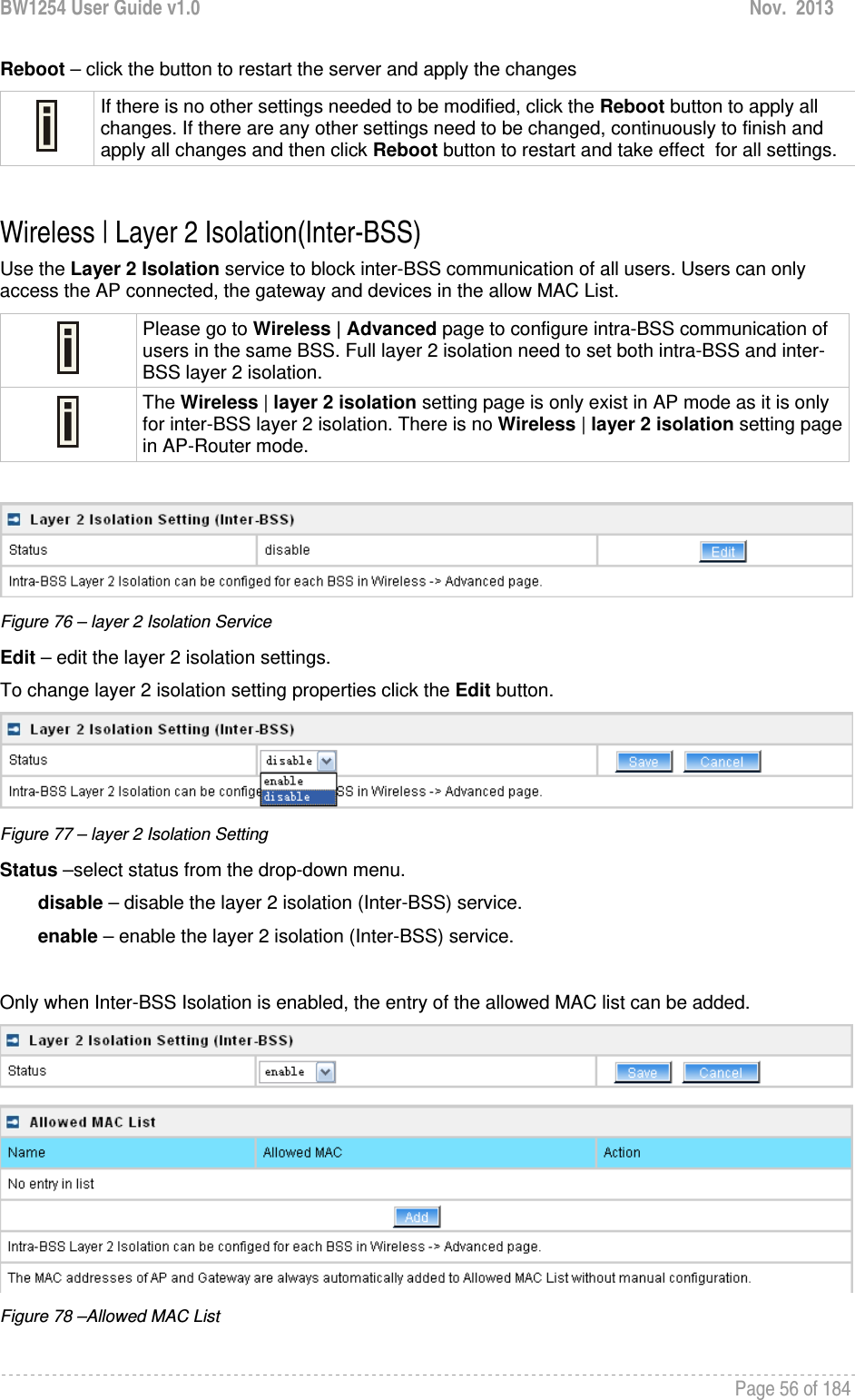
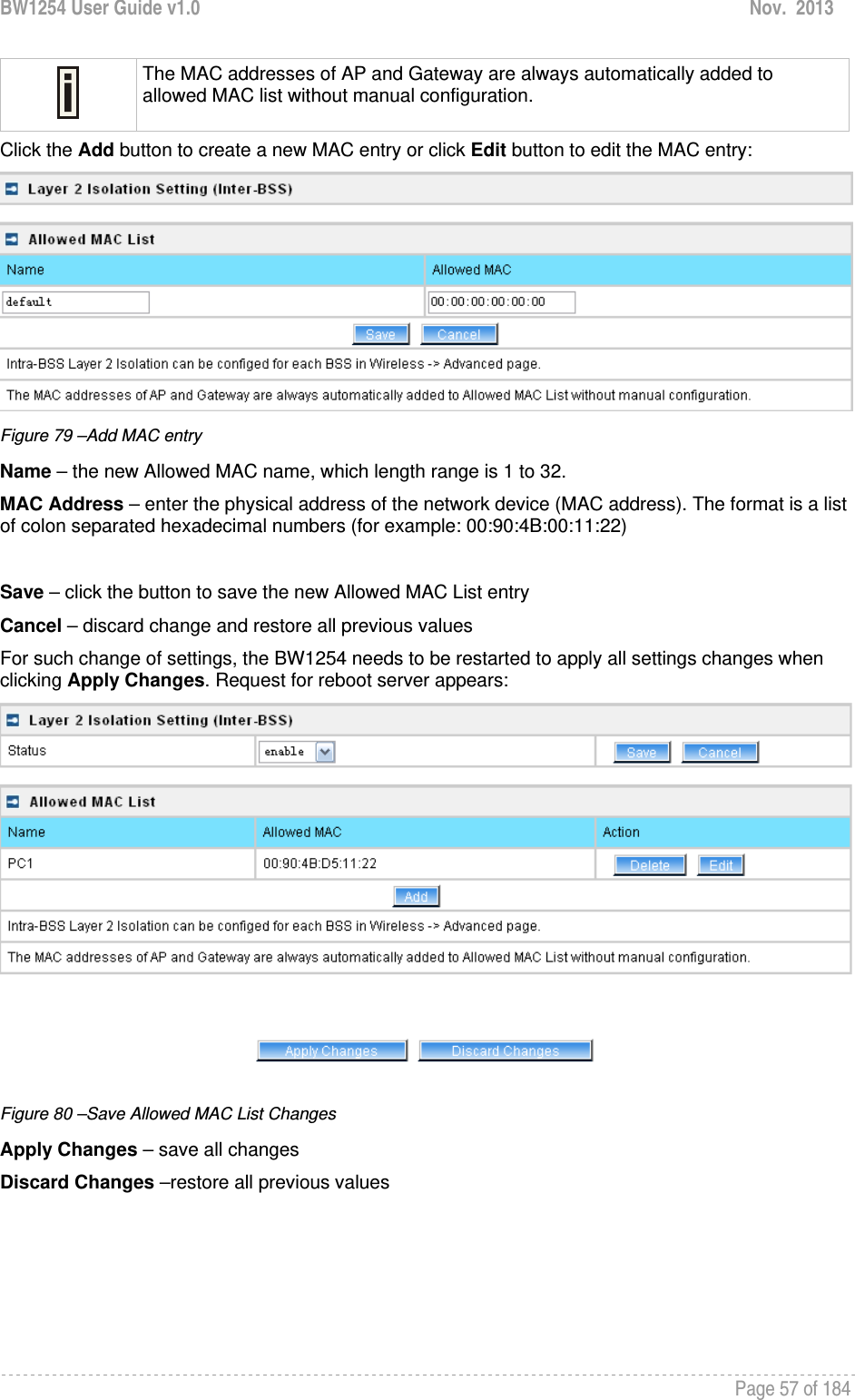
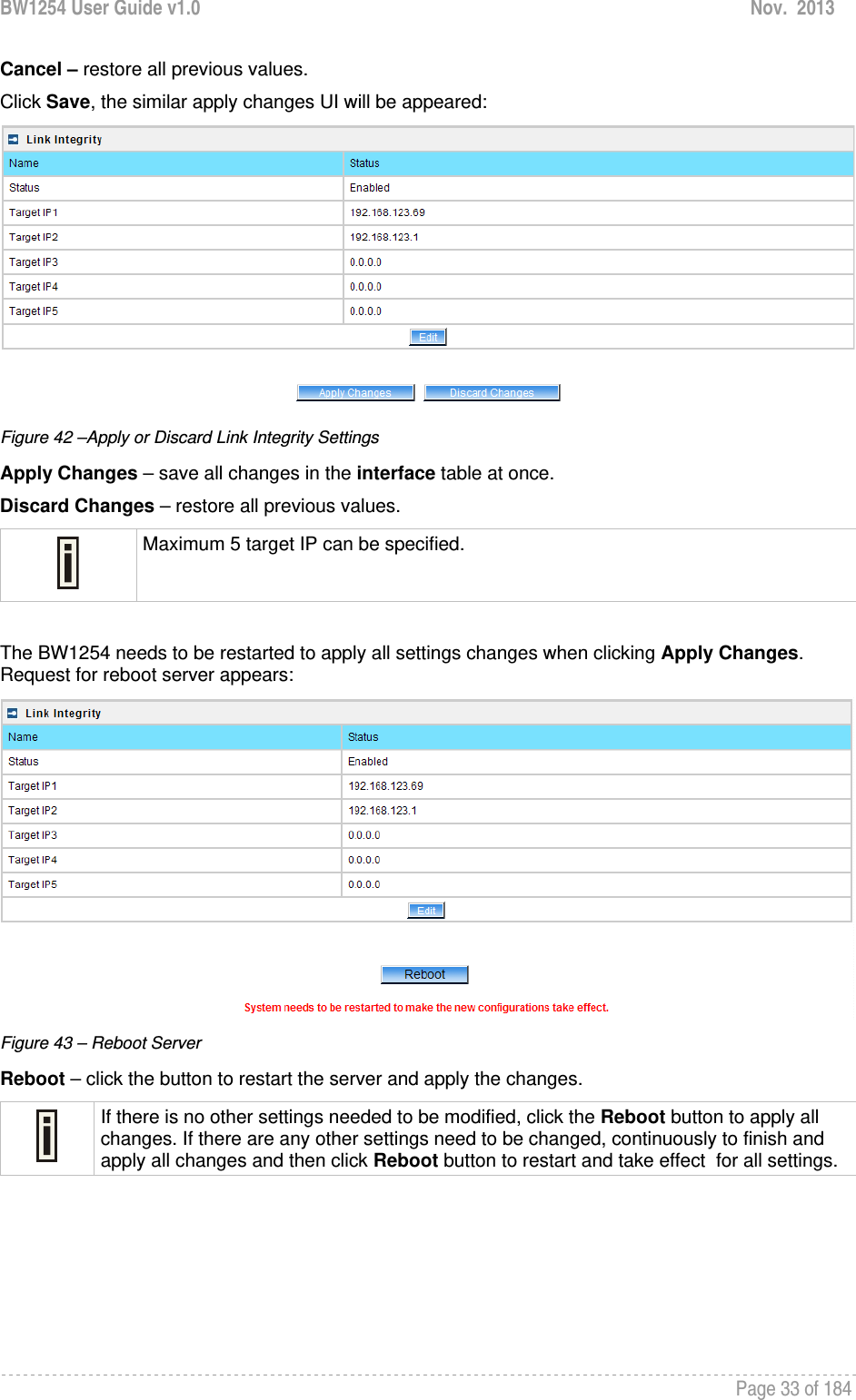
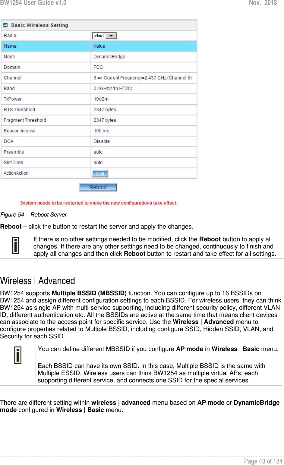
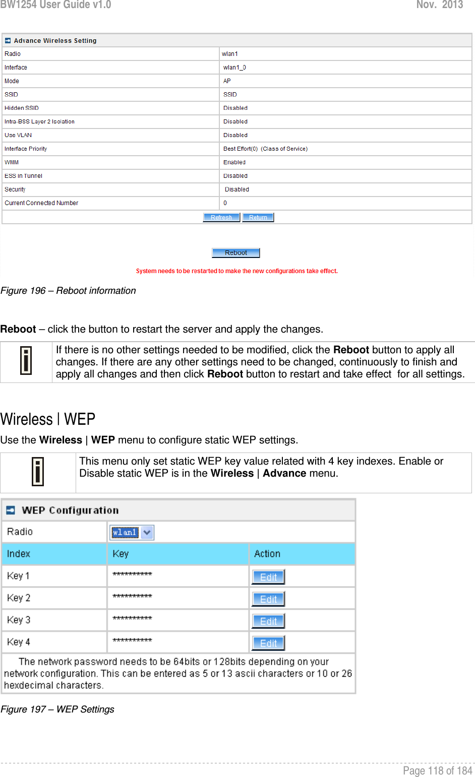
![BW1254 User Guide v1.0 Nov. 2013 Page 58 of 184 Figure 81 –apply changes Reboot – click the button to restart the server and apply the changes If there is no other settings needed to be modified, click the Reboot button to apply all changes. If there are any other settings need to be changed, continuously to finish and apply all changes and then click Reboot button to restart and take effect for all settings. Wireless | Neighbor List The neighbor list will scan neighbor access point to show the RSSI, channel…etc information in the environment. Figure 82 – neighbor list Click Scan 2.4G or Scan 5G button. SSID – the SSID of scanned access point MAC address – the MAC address of scanned access point RSSI(dBm) – the RSSI of scanned access point(in dBm) Channel –the channel of scanned access point Co-Channel – display if the neighbor access point channel same with BW1254.[“Y”,yes/”N”,no] Adjacent Interference –display the neighbor access point channel adjacent to BW1254.[“Y”,yes or “N”,no]. It is based on the neighbor within 4 channels of BW1254. For instance, if BW1254 channel is 6 then the neighbor access point will be marked “Y” if its channel is 2,3,4,5 or 7,8,9,10.](https://usermanual.wiki/BROWAN-COMMUNICATIONS/1254XW.manual/User-Guide-2191248-Page-59.png)
![BW1254 User Guide v1.0 Nov. 2013 Page 59 of 184 Wireless | Priority 5G The priority connection for dual band client. When the wlan1(2.4G) and wlan2(5G) configure same SSID, the 5G frequency will prior to 2.4G connection if the client support dual band frequency. Once WLAN1 and WLAN2 configure same SSID, the interface and SSID will display automatically. Otherwise there will be nothing display in this page. Figure 83 – priority 5G Click Edit button to configure it. Figure 84 – enable 5G priority Interface – the interface of BW1254 SSID – the SSID of BW1254.[both 2.4G and 5G] Reject counter – the counter that AP will reject 2.4G client connection Interval second – the interval second during every reject counter Delay – delay time of reject counter. Enable – enable or disable the function.[check box or not] Save/cancel – save/cancel configuration Click apply changes or discard changes button to apply or discard the setting. Figure 85 – apply/discard changes Reboot device Figure 86 – reboot device](https://usermanual.wiki/BROWAN-COMMUNICATIONS/1254XW.manual/User-Guide-2191248-Page-60.png)
![BW1254 User Guide v1.0 Nov. 2013 Page 61 of 184 User User | Users The User | Users menu shows the statistics of connected users. The user can be monitored and managed such as drop from the network. Figure 87 – User’s statistics User – show the connected client’s MAC address Interface – show which BSS the client connected to User IP – IP address, from which the user’s connection is established [digits and dots] Authed – indicate this client is authenticated or not Wireless Auth – show the authentication method which user used to connect Time Length – session duration since the user login [hh:mm:ss] Idle Time – amount of user inactivity time [hh:mm:ss] Action – view the statistics or kickoff the user. Detail – click on user details to get more information about the client: Kickoff – logout the user.](https://usermanual.wiki/BROWAN-COMMUNICATIONS/1254XW.manual/User-Guide-2191248-Page-62.png)
![BW1254 User Guide v1.0 Nov. 2013 Page 62 of 184 Figure 88 – User’s Details MAC address – hardware address of the network device from which the user is connected L2 Auth – show layer2 authentication status, including all supported EAP type of 802.1x auth and MAC auth WISP – WISP domain name where the user belongs Session ID – the unique user’s session ID number. This can be used for troubleshooting purposes Remaining Time Length – remaining user’s session time [hh:mm:ss]. Session time for user is defined in the RADIUS Server Idle time – specify current idle time. Idle Timeout – specify the time of user idle timout [hh:mm:ss]. When reach the time, the user will be logged out automatically. Input Bytes – amount of data in bytes which the user network device has received [Bytes] Output Bytes – amount of data in bytes, transmitted by the user network device [Bytes] Remaining Input/Output Bytes – user session remaining input/output bytes. WISPr Operator can define the user session in bytes. Remaining bytes is received from RADIUS [Bytes/unlimited]](https://usermanual.wiki/BROWAN-COMMUNICATIONS/1254XW.manual/User-Guide-2191248-Page-63.png)
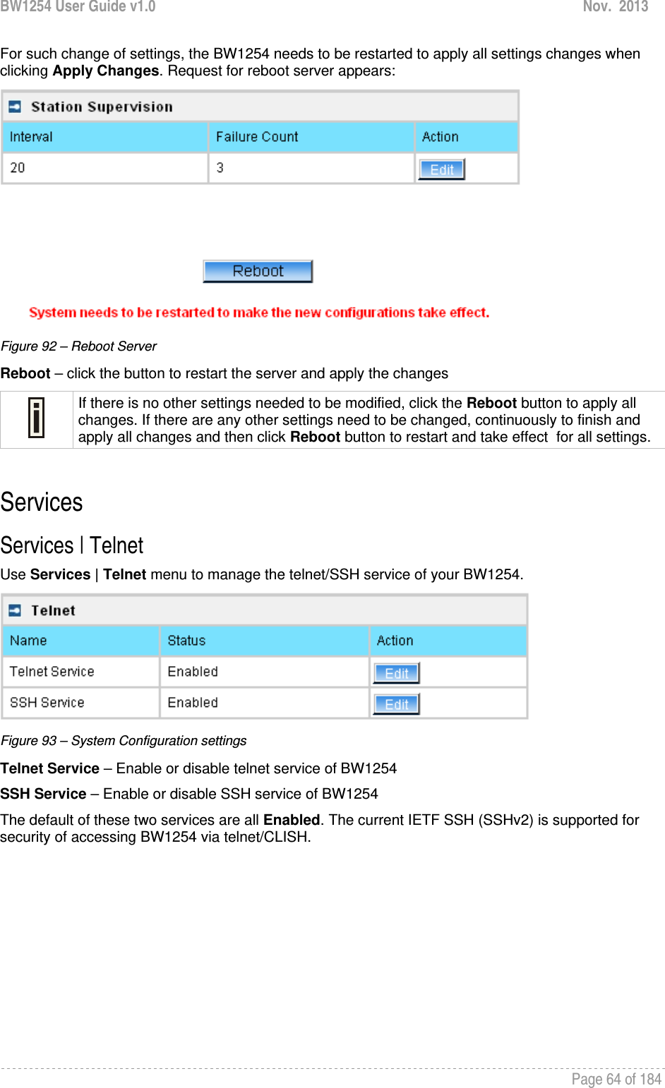
![BW1254 User Guide v1.0 Nov. 2013 Page 63 of 184 Remaining Total Bytes –user session remaining total bytes. WISPr Operator can define the user session in bytes. Remaining bytes is received from RADIUS [Bytes/unlimited] Bandwidth Downstream/Upstream – user upstream and downstream bandwidth [in bps] Back – returns to connect client’s statistics list Kickoff –click this button to logout the user from access point. Refresh – click the button to refresh users’ statistics User | Station Supervision The Station Supervision function is used to monitor the connected host station availability. This monitoring is performed with ping. If the specified number of ping failures is reached (failure count), the user is logged out from the BW1254. Figure 89 – Station Supervision To adjust the ping interval/failure count, click the Edit button. Figure 90 – Edit Station Supervision Interval – define interval of sending ping to host [in seconds] Failure Count – failure count value after which the user is logged out from the system Save – save station supervision settings Cancel – cancel changes Change status or leave in the default state if no editing is necessary and click the Save button. Figure 91 –Apply or Discard Station Supervision Changes Apply Changes – to save all changes made in the interface table at once Discard Changes – restore all previous values](https://usermanual.wiki/BROWAN-COMMUNICATIONS/1254XW.manual/User-Guide-2191248-Page-64.png)
![BW1254 User Guide v1.0 Nov. 2013 Page 65 of 184 Services | SNMP SNMP is the standard protocol that regulates network management over the Internet. To communicate with SNMP manager you must set up the same SNMP communities and identifiers on both ends: manager and agent. Use the Services | SNMP menu to change current SNMP configuration. Figure 94 – SNMP settings Readonly community – community name is used in SNMP version 1 and version 2c. Read-only (public) community allows reading values, but denies any attempt to change values [1-32 all ASCII printable characters, no spaces] Readwrite community – community name is used in SNMP version 1 and version 2c. Read-write (private) community allows to read and (where possible) change values [1-32 all ASCII printable characters, no spaces] Default Trap community – the default SNMP community name used for traps without specified communities. The default community by most systems is "public". The community string must match the community string used by the SNMP network management system (NMS) [1-32 all ASCII printable characters, no spaces] HeartBeat Trap Interval – defined the AP sending the trap interval to the SNMP server.[second] Trap Configuration Table: You can configure your SNMP agent to send SNMP Traps (and/or inform notifications) under the defined host (SNMP manager) and community name (optional). Click Add to add a new SNMP manager or Delete to delete a specific SNMP manager. Clicking Add: Figure 95 – Add SNMP Trap Host IP – enter SNMP manager IP address [dots and digits] Host Port – enter the port number the trap messages should be send through [number] Trap Type – select trap message type [v1/v2/inform]](https://usermanual.wiki/BROWAN-COMMUNICATIONS/1254XW.manual/User-Guide-2191248-Page-66.png)
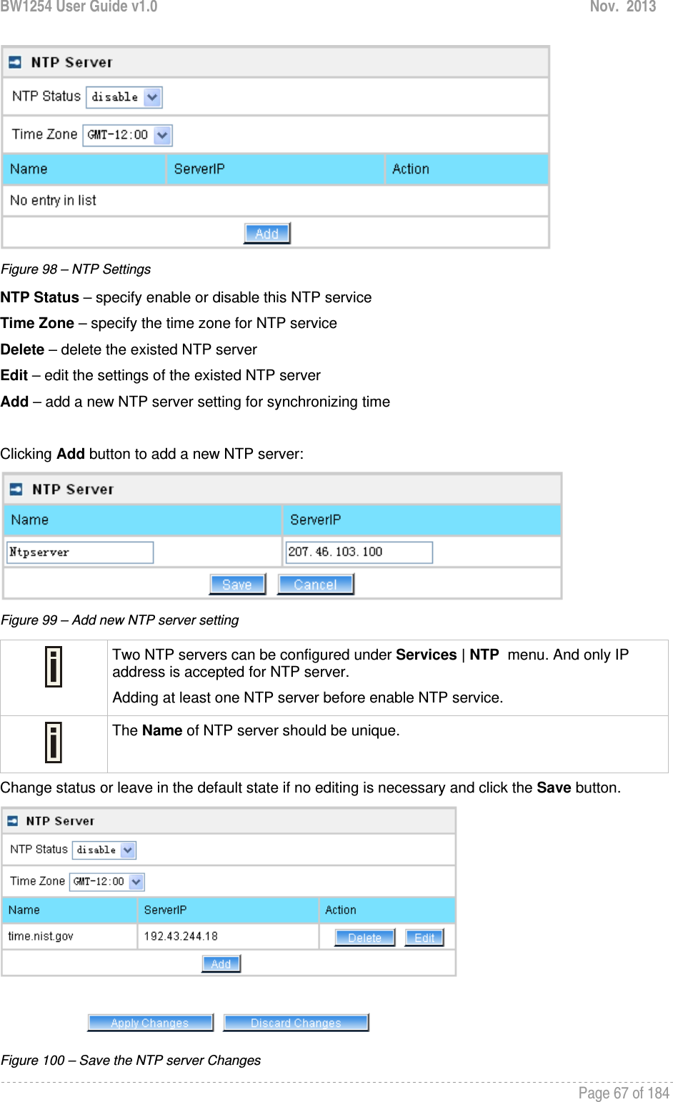
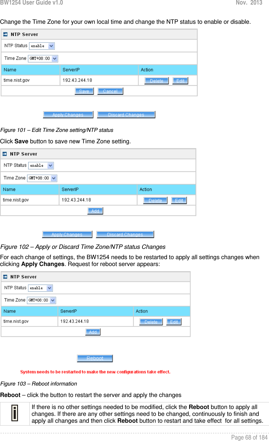
![BW1254 User Guide v1.0 Nov. 2013 Page 66 of 184 Community – specify the community name at a SNMP trap message. This community will be used in trap messages to authenticate the SNMP manager. If not defined, the default trap community name will be used (specified in the SNMP table) [1-32 all ASCII printable characters, no spaces] Save – save all current settings Cancel – restore the last settings Services | Time Configure the system time manually under Services | Time Settings menu. Figure 96 – Time Settings Click Edit to change current system time. Figure 97 – Edit Date and Time Settings Date – [yy/mm/dd] Time – [hour/minute] Change the Date and Time or leave in the default value if no editing is necessary and click the Apply button. Thus the modified time will be taken effect at once. No reboot is needed. If NTP is enabled, the local time cannot be modified. Since BW1254 hasn’t RTC (real-time clock), the system time will back to 1970/01/01 00:00 after reboot. Services | NTP NTP (Network Time Protocol) is used to synchronize the system time with the selected network NTP server. Use the Services | NTP menu to configure the NTP service:](https://usermanual.wiki/BROWAN-COMMUNICATIONS/1254XW.manual/User-Guide-2191248-Page-67.png)
![BW1254 User Guide v1.0 Nov. 2013 Page 70 of 184 System System | Administrator The System | Administrator menu is for changing the administrator’s settings: username and password: Figure 107 – system security settings User Name – administrator username for access to BW1254 (e.g. web interface, CLI mode) [1-32 symbols, spaces not allowed] Old Password – old password New Password – new password value used for user authentication in the system [4-8 characters, spaces not allowed] Confirm Password – re-enter the new password to verify its accuracy Save – click to save new administrator settings. Default administrator logon settings are: User Name: admin Password: admin01 Password length is from 4 to 8 characters. After filling in the right Old password and the New Password, clicking the Save button for taking effect immediately. After clicking Save button, the below UI will be shown to notify that the new password setting has been taken place: Figure 108 – system security settings save and take effect successfully](https://usermanual.wiki/BROWAN-COMMUNICATIONS/1254XW.manual/User-Guide-2191248-Page-71.png)
![BW1254 User Guide v1.0 Nov. 2013 Page 71 of 184 System | System Log Use the System | System Log menu to trace your AP system processes and get the system log locally or on the remote log server. Figure 109 – System Log settings To enable the System Log remote sending function, click the Edit button on the Remote System Log table and choose the enabled option: Figure 110 – Configure Remote System Log Utility Remote Log Status – choose disable/enable remote log function.[enabled/disabled] Host IP – specify the host IP address where to send the System Log messages [dots and digits] Log Level – specify the remote log message level you want to trace [critical, error, warning, info and debug] Do not output “debug” log unless there are important issue needs to be clarified. Debug log will output all of the information so that it will severely drop down the network performance. BW1254 support standard sys. log server. Save – save changes Cancel – restore the previous values To view the System Log locally, click the Edit button on the Local System Log table and choose the enabled option: Figure 111 –Configure Local System Log](https://usermanual.wiki/BROWAN-COMMUNICATIONS/1254XW.manual/User-Guide-2191248-Page-72.png)
![BW1254 User Guide v1.0 Nov. 2013 Page 72 of 184 Local Log Status – choose disable/enable local log [enabled/disabled] Log Limit – specify the maximum length of local log message in byte [20000-512000] Log Level – specify the local log message level you want to trace [critical, error, warning, info and debug] Save – save changes Cancel – restore the previous values View – view the log messages locally Click View button, a similar screen will appear as below: Figure 112 – View Local Log Messages Clear – clear current log message Refresh – get the updated log messages Return – back to System Log page System | System Mode In this page, you can select the system mode of your BW1254. Figure 113 – System Mode Settings Mode – select whether the system mode of BW1254 is AP mode or AP Router mode AP – The Ethernet interface and wireless interface will bridge into the same interface working as transparent access point.](https://usermanual.wiki/BROWAN-COMMUNICATIONS/1254XW.manual/User-Guide-2191248-Page-73.png)
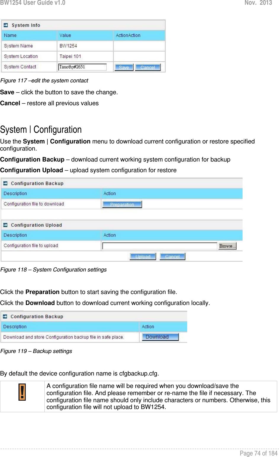
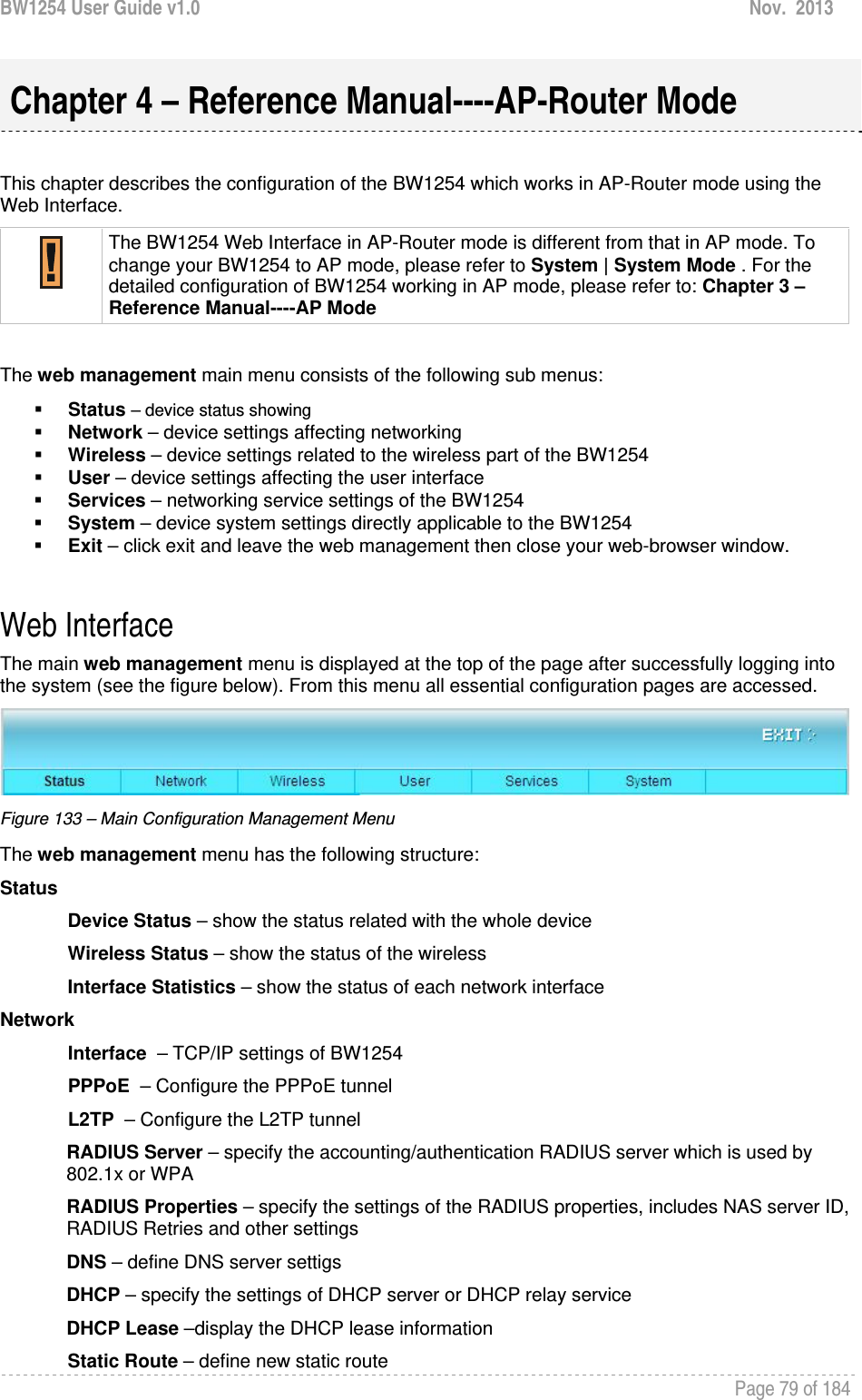
![BW1254 User Guide v1.0 Nov. 2013 Page 73 of 184 AP Router – A wireless router is a device that performs the functions of a router but also includes the functions of a wireless access point. Under this mode the Ethernet will act as WAN interface and wireless interface will be act as LAN. IP – specify the IP address of current interface [dots and digits] Netmask – specify the subnet mask of current interface [dots and digits] Gateway – specify the gateway to other networks Protocol – specify static for setting IP address manually and dhcp for getting IP address dynamically acting as DHCP client Apply and Reboot – click the button to restart the device and apply all setting changes The BW1254 Web Interface in AP mode is different from that in AP-Router mode. For the detailed configuration of BW1254 working in AP-Router mode, please refer to the next chapter: Chapter 4 – Reference Manual----AP-Router Mode System | System Info Administrator can self-define the device information including the system name, system location and system contact information of his BW1254. Figure 114 – System info Settings System Name – edit the system name, the column length range is 1 to 255. Figure 115 –edit the system name System Location – edit the system location, the column length range is 1 to 255. Figure 116 –edit the system location System Contact – edit the system contact, the column length range is 1 to 255.](https://usermanual.wiki/BROWAN-COMMUNICATIONS/1254XW.manual/User-Guide-2191248-Page-74.png)
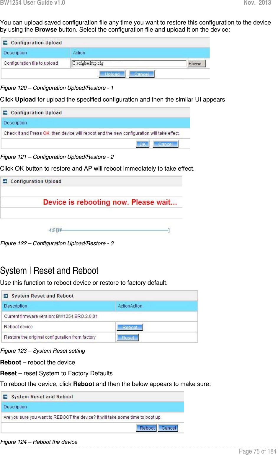

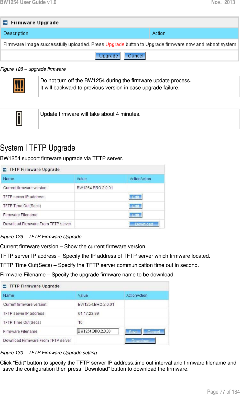
![BW1254 User Guide v1.0 Nov. 2013 Page 78 of 184 Please make sure the firmware is correct for BW1254. Otherwise the upgrade will be failed. Do not turn off the BW1254 during the firmware update process. It will backward to previous version in case upgrade failure. System | Location Settings You can define the longitude and latitude for the device information or for the NMS to locate the device location. Figure 131 – location setting Click edit to enter the Longitude and Latitude in digit and dot format. Figure 132 – edit location[longitude/latitude] Click save button to save it.](https://usermanual.wiki/BROWAN-COMMUNICATIONS/1254XW.manual/User-Guide-2191248-Page-79.png)
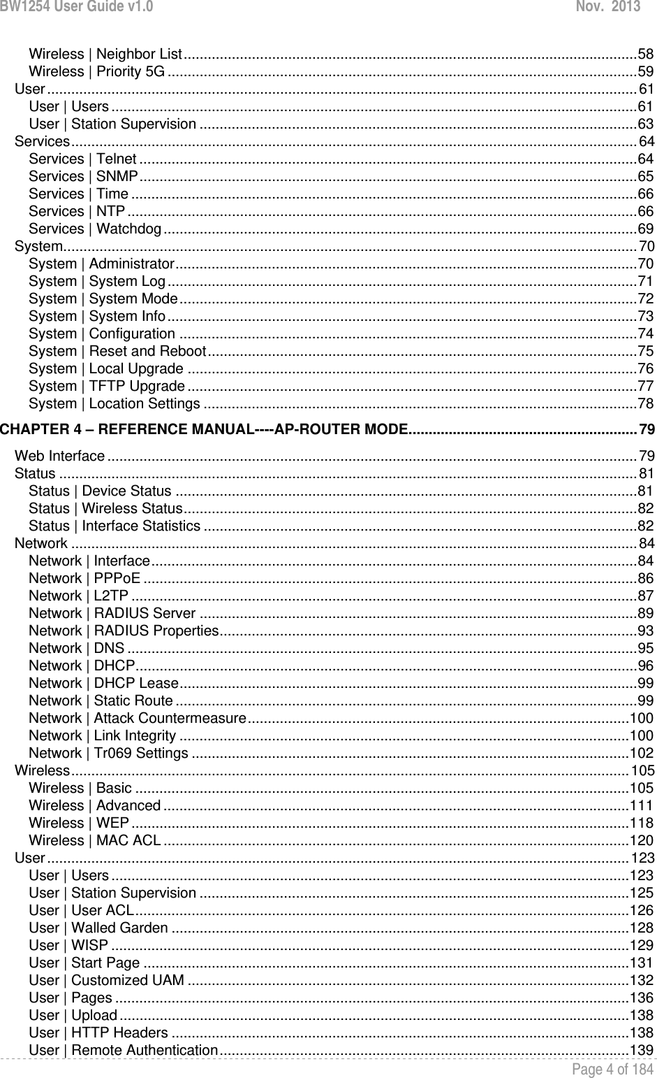
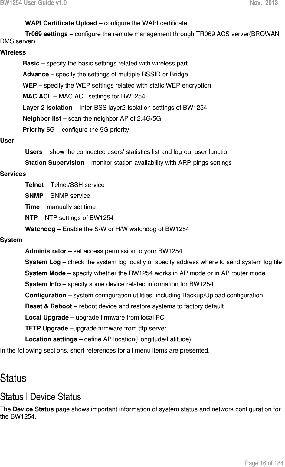
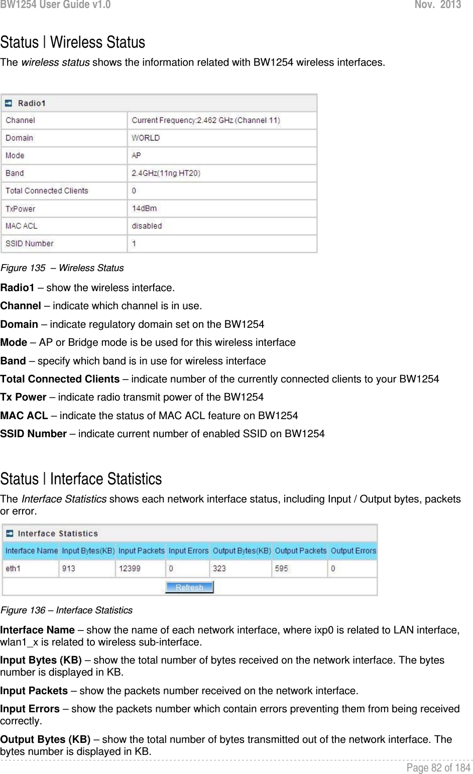
![BW1254 User Guide v1.0 Nov. 2013 Page 81 of 184 Status Status | Device Status The Device Status page shows important information of system status and network configuration for the BW1254. Figure 134 – Device Status System Mode – display the BW1254 works in AP mode or AP-Router mode System Version – display the current version of the firmware loaded to the AP This is important information for support requests and for preparing firmware upgrading Config version – display current configure version Up Time – indicate the time, expressed in days, hours and minutes since the system was last rebooted System Time – show the current time of the BW1254 WLAN1 MAC – show the MAC addresses of the wireless interfaces of the BW1254[2G] WLAN2 MAC – show the MAC addresses of the wireless interfaces of the BW1254[5G] Free System Memory – indicate the memory currently available in the BW1254 Total System Memory – indicate the total memory in the BW1254 WAN Mode – indicate static IP or DHCP client is used for BW1254 WAN IP address WAN IP – show the WAN IP address of BW1254 WAN Mask – show the WAN Network Mask of BW1254 Gateway – show the default gateway of BW1254](https://usermanual.wiki/BROWAN-COMMUNICATIONS/1254XW.manual/User-Guide-2191248-Page-82.png)
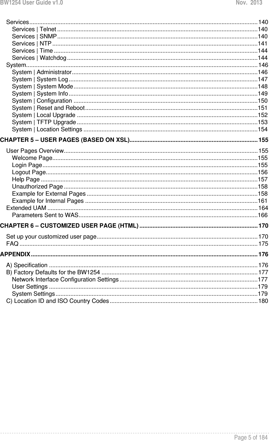
![BW1254 User Guide v1.0 Nov. 2013 Page 84 of 184 Network Network | Interface The AP-Router contains two kinds of network interfaces: eth1 is worked as wide area network (WAN) interface for Access Points; each BSS interface is worked as local area network (LAN) interface which bridge into the br0 interface. The WAN port connects to the Internet or the service provider’s backbone network. Each BSS can be looked as a virtual AP, wlan1_0 is the virtual AP for wireless network. All these interfaces are listed in the Network Interfaces page. All network interfaces available in the AP-Router are shown in the following table: Figure 137 – Network Interface Table To change network interface configuration properties click the Edit button in the Action column. The status can be changed now: Figure 138 – Edit Network Interfaces Settings - 1 Interface – standard interface name. This name cannot be edited Status – select the status of interface [enabled/disabled] Do not disable the interface through which you are connected to the AP Router. Disabling such interface will lose your connection to the device. The interface eth1 can not be disabled. Type – network type cannot be changed. There are two possible networking types: LAN – interface is used as local area network (LAN) gateway, and is connected to a LAN WAN – interface is used to access the ISP network NAT – select enable/disable the NAT service of current interface. If enabled, users can access the Internet under its network gateway address [enabled/disabled] Web Auth – select enable/disable the Web Login Authentication of current interface. With disabled authentication, the user from his LAN gets access to the Internet without any authentication. If enabled, authentication for Internet access is required for all users [enabled/disabled]](https://usermanual.wiki/BROWAN-COMMUNICATIONS/1254XW.manual/User-Guide-2191248-Page-85.png)
![BW1254 User Guide v1.0 Nov. 2013 Page 85 of 184 Change status or leave in the default state if no editing is necessary and click the Continue button. Then the following parameters can be changed: Figure 139 –Edit Interface Configuration Settings - 2 IP Address – specify new interface IP address [dots and digits] Under ap-router mode,IP address of each interface should be configured different subnet; otherwise, you will receive an error message. Netmask – specify the subnet mask [[0-255].[0-255].[0-255].[0-255]]. These numbers are a binary mask of the IP address, which defines IP address order and the number of IP addresses in the subnet Gateway – interface gateway. For LAN type interfaces, the gateway is WAN interface. The gateway of the WAN interface is usually the gateway router of the ISP or other WAN network [Default gateway is marked with ‘*’] Save – save the entered values. Cancel – restore all previous values. Figure 140 – Apply or Discard Interface Configuration Changes Apply Changes – save all changes in the interface table at once. Discard Changes – restore all previous values. For such change of settings, the BW1254 needs to be restarted to apply all settings changes when clicking Apply Changes. Request for reboot server appears:](https://usermanual.wiki/BROWAN-COMMUNICATIONS/1254XW.manual/User-Guide-2191248-Page-86.png)
![BW1254 User Guide v1.0 Nov. 2013 Page 86 of 184 Figure 141 – Reboot Server Reboot – click the button to restart the server and apply the changes. If there is no other settings needed to be modified, click the Reboot button to apply all changes. If there are any other settings need to be changed, continuously to finish and apply all changes and then click Reboot button to restart and take effect for all settings. Network | PPPoE The Point-to-Point Protocol over Ethernet(PPPoE) is a network protocol for encapsulating PPP frames inside Ethernet frames. It is use mainly for DSL service. Click Edit button to enable or disable the service. Figure 142 – PPPoE service Name – service name Status – change status for this service.[disable/enable] Figure 143 – change PPPoE service Enable the PPPoE service. Username – enter the authorized user to connect to the server [text string, can not be empty]. The same username should be configured on the PPPoE server. Password – the password of the user. [text string, can not be empty]](https://usermanual.wiki/BROWAN-COMMUNICATIONS/1254XW.manual/User-Guide-2191248-Page-87.png)
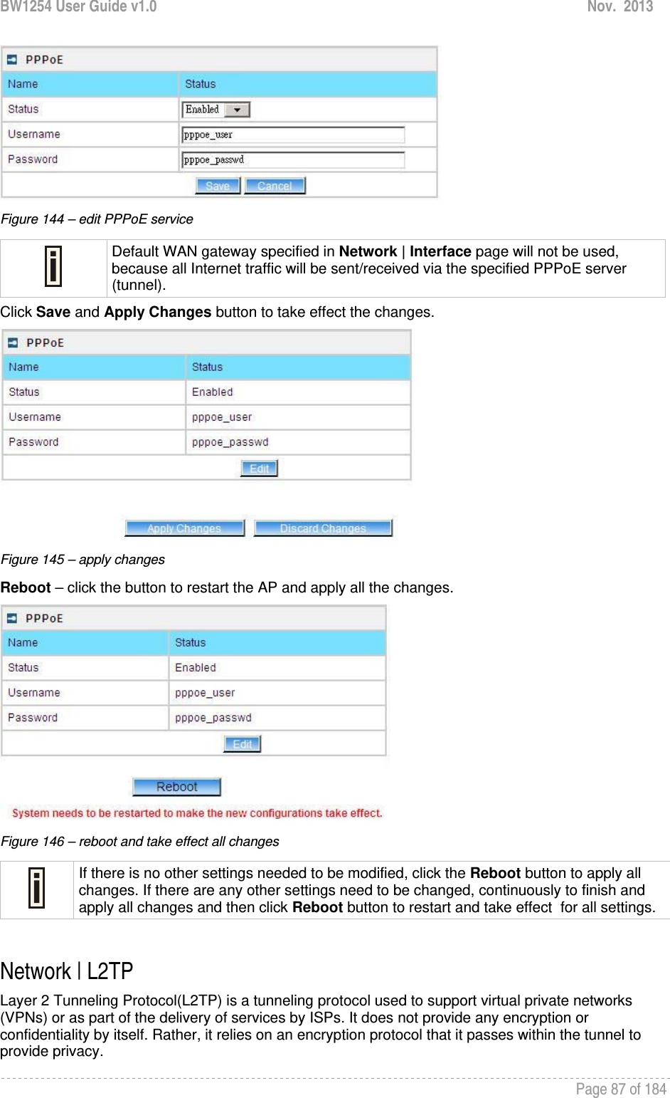
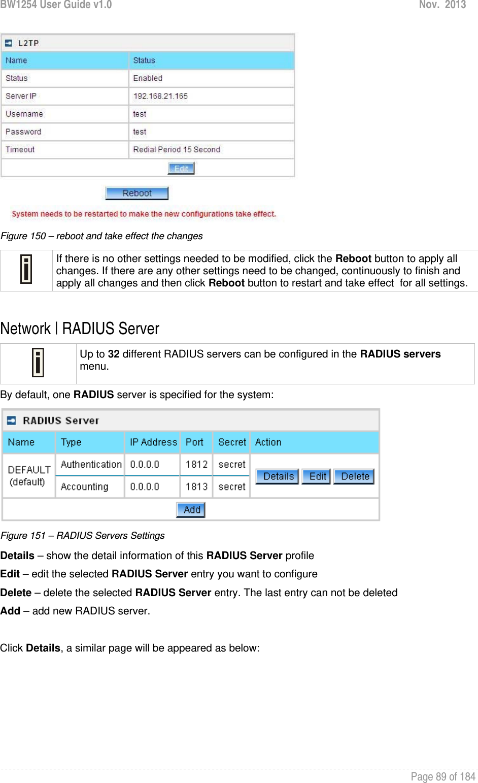
![BW1254 User Guide v1.0 Nov. 2013 Page 88 of 184 Click Edit button to enable or disable the service. Figure 147 – L2TP services Name – service name Status – change status for this service.[disable/enable] Server IP – enter the server IP address. [in digits and dots notation, e.g. 192.168.2.2] Username – enter the user name. Password – password for the authorized user. Timeout – in case of connection fail, the interval to re-connect to the server. Figure 148 – edit L2TP services Click Save button and Apply Changes button to save the change or discard changes button to discard the change Figure 149 – save the changes Reboot – click the button to restart the AP and apply all the changes.](https://usermanual.wiki/BROWAN-COMMUNICATIONS/1254XW.manual/User-Guide-2191248-Page-89.png)

![BW1254 User Guide v1.0 Nov. 2013 Page 91 of 184 Figure 153 – Edit the RADIUS Server’s profile Figure 154 – Add a new RADIUS Server's profile Name – specify the new RADIUS server name which is used for selecting RADIUS server Default – specify this RADIUS profile as default or not. When selected, the profile will be used as default Authentication IP – specify the IP address of Authentication RADIUS server [dots and digits] Authentication Port –specify the network port used to communicate with the Authentication RADIUS server [1-65535] Authentication Secret – shared secret string that is used to make sure the integrity of data frames used for the Authentication RADIUS server Accounting IP – specify the IP address of Accounting RADIUS server [dots and digits]](https://usermanual.wiki/BROWAN-COMMUNICATIONS/1254XW.manual/User-Guide-2191248-Page-92.png)
![BW1254 User Guide v1.0 Nov. 2013 Page 92 of 184 Accounting Port –specify the network port used to communicate with the Accounting RADIUS server [1-65535] Accounting Secret – shared secret string that is used to make sure the integrity of data frames used for the Accounting RADIUS server The default port value for authentication is 1812. The default port value for accounting is 1813. The port specified here must be the same with the one on the RADIUS server. User Password Md5sum Secret – if enabled, user input password will be calculated md5-sum before pass to RADIUS server for more security [enabled/disabled] This setting needs RADIUS server do relevant configurations. Save –save the entered values Cancel – restore all previous values After adding a new RADIUS server or editing an existing one, a page appears similar to the following: Figure 155 – Apply or Discard RADIUS Server Changes Details – show the detail information of this RADIUS Server profile Edit – edit the selected RADIUS Server entry you want to configure Delete – delete the selected RADIUS Server entry. The last entry can not be deleted Add – add new RADIUS server. Apply Changes – to save all changes at once. Discard Changes – restore all previous values. Click Apply Changes to apply all the changes. Then the follow similar page will appear:](https://usermanual.wiki/BROWAN-COMMUNICATIONS/1254XW.manual/User-Guide-2191248-Page-93.png)
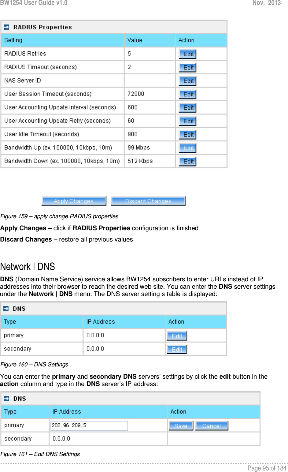
![BW1254 User Guide v1.0 Nov. 2013 Page 93 of 184 Figure 156 – Reboot Server Reboot – restart the access point to make applied changes work. If there is no other settings needed to be modified, click the Reboot button to apply all changes. If there are any other settings need to be changed, continuously to finish and apply all changes and then click Reboot button to restart and take effect for all settings. Network | RADIUS Properties General RADIUS settings are configured using the RADIUS Properties menu under the network: Figure 157 – RADIUS Properties settings RADIUS Retries – retry count of sending RADIUS packets before giving up [0-99] RADIUS Timeout (seconds) – maximum amount of time before retrying RADIUS packets [1-999] NAS Server ID – name of the RADIUS client](https://usermanual.wiki/BROWAN-COMMUNICATIONS/1254XW.manual/User-Guide-2191248-Page-94.png)
![BW1254 User Guide v1.0 Nov. 2013 Page 94 of 184 User Session Timeout (seconds) – amount of time from the user side (no network carrier) before closing the connect [1-999999999] User Accounting Update Interval (Seconds) – period after which server should update accounting information [60-999999999] User Accounting Update Retry (seconds) – retry time period in which server should try to update accounting information before giving up [60-999999999] User Idle Timeout (seconds) – amount of user inactivity time, before automatically disconnecting user from the network [1-999999999] Bandwidth Up – maximum bandwidth up at which corresponding user is allowed to transmit [bps] Bandwidth Down – maximum bandwidth down at which corresponding user is allowed to receive [bps] Each setting in this table can be edited. Select RADIUS setting you need to update, click the edit next to the selected setting and change the value: Figure 158 – edit RADIUS properties Use the save button to save an entered value. Now select another RADIUS property to edit, or Apply Changes and restart your AP if the configuration is finished:](https://usermanual.wiki/BROWAN-COMMUNICATIONS/1254XW.manual/User-Guide-2191248-Page-95.png)
![BW1254 User Guide v1.0 Nov. 2013 Page 96 of 184 IP Address – enter the primary or secondary DNS server’s IP address [dots and digits] Change status or leave in the default state if no editing is necessary and click the Save button. Figure 162 – Apply or Discard DNS server Settings For each change of settings, the BW1254 needs to be restarted to apply all settings changes when clicking Apply Changes. Request for reboot server appears: Figure 163 – Reboot information Reboot – click the button to restart the server and apply the changes. If there is no other settings needed to be modified, click the Reboot button to apply all changes. If there are any other settings need to be changed, continuously to finish and apply all changes and then click Reboot button to restart and take effect for all settings. Network | DHCP In AP Router mode, the BW1254 can act as a DHCP Server. The DHCP (Dynamic Host Configuration Protocol) service is supported on the LAN interfaces. This service enables clients on the LAN to request configuration information, such as an IP address, from a server. This service can be viewed in the following table: Figure 164 – DHCP Configuration](https://usermanual.wiki/BROWAN-COMMUNICATIONS/1254XW.manual/User-Guide-2191248-Page-97.png)
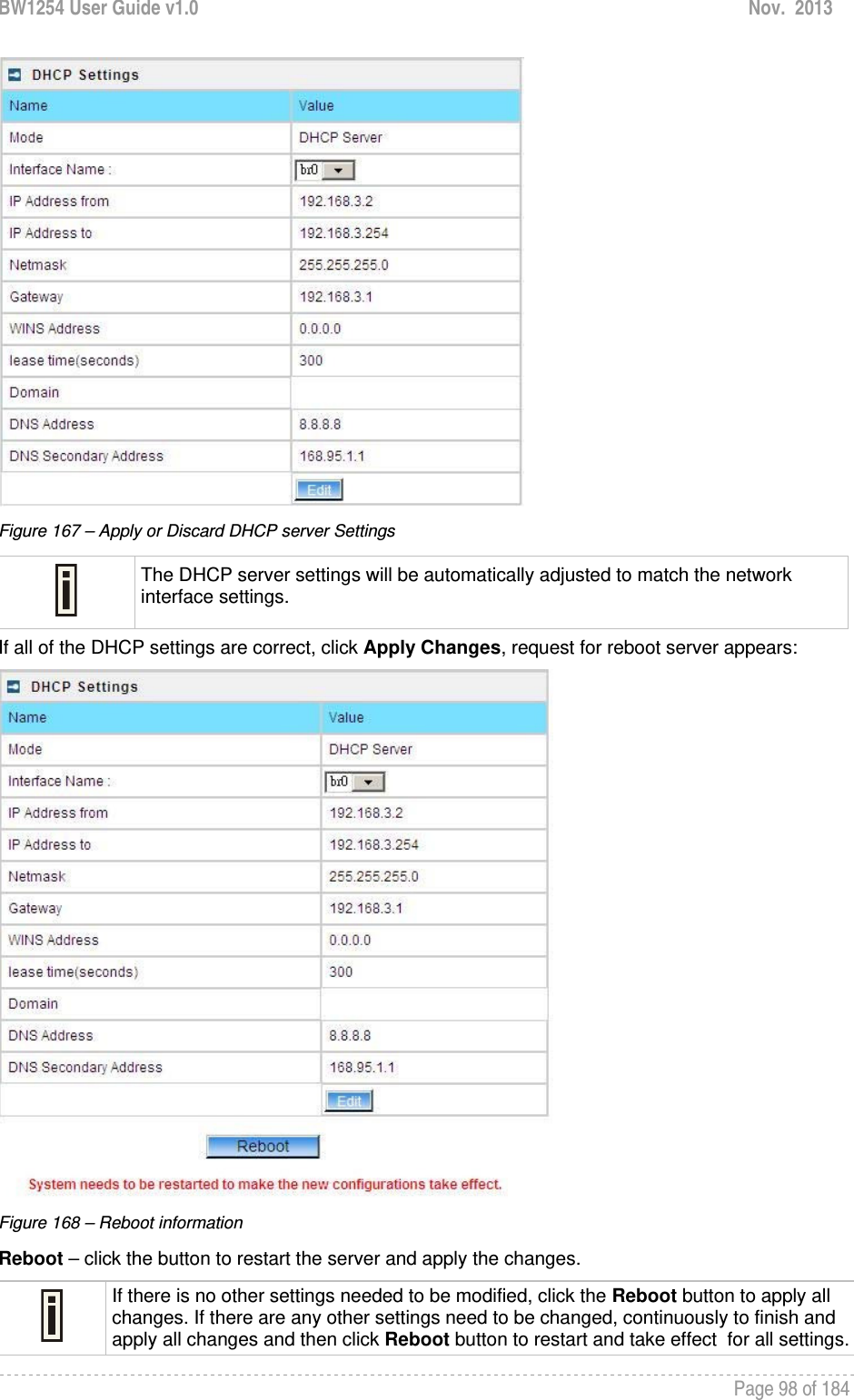
![BW1254 User Guide v1.0 Nov. 2013 Page 97 of 184 Interface Name – select which LAN interface to be configured.[only br0 interface in BW1254] Select the interface, and then click Edit button, a similar screen will appear as below: Figure 165 – Set DHCP Mode Mode – DHCP service mode [DHCP server/Disabled] When DHCP Server is selected, a page appears similar to the following: Figure 166 – DHCP Server Settings IP Address from/IP Address to – specify the IP address range supported for the DHCP service [mandatory fields] Netmask – show the subnet mask of current interface Gateway – show the interface gateway WINS (Windows Internet Naming Service) Address – specify service IP address if it is available on the network [dots and digits] Lease Time – specify the IP address renewal in seconds [1-1000000] Domain – specify DHCP domain name [optional, 1-128 sting] DNS Address – specify the DNS server’s IP address [digits and dots] DNS Secondary Address – specify the secondary DNS server’s IP address [digits and dots] The DNS address is same with the setting in the Network | DNS menu. Change status or leave in the default state if no editing is necessary and click the Save button.](https://usermanual.wiki/BROWAN-COMMUNICATIONS/1254XW.manual/User-Guide-2191248-Page-98.png)
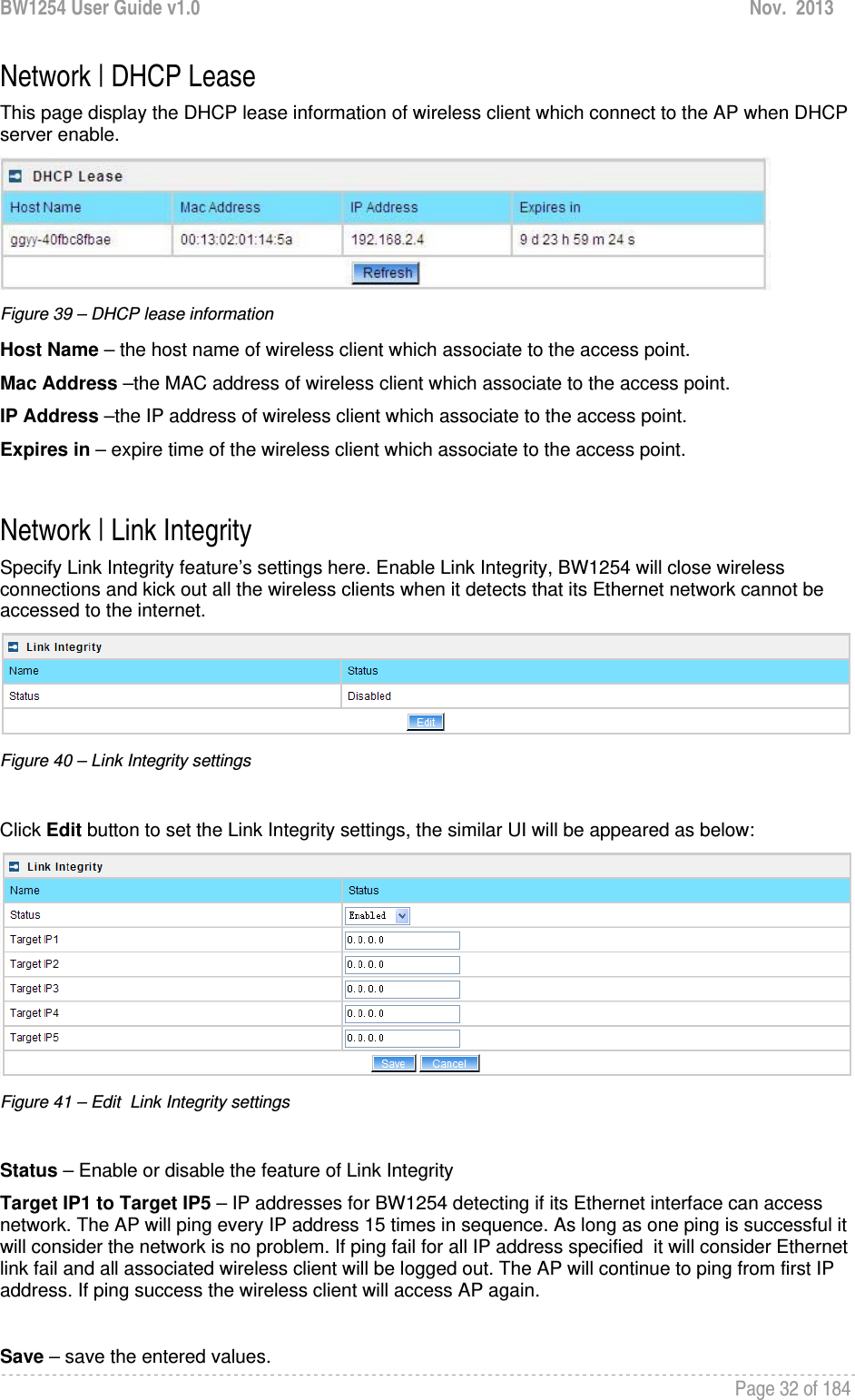
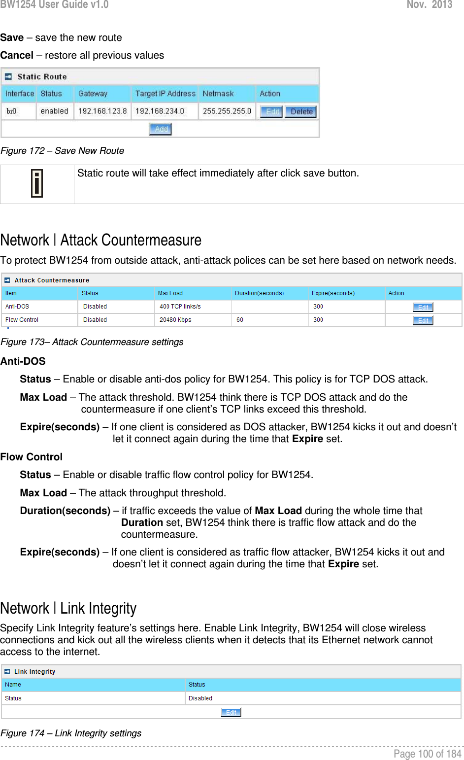
![BW1254 User Guide v1.0 Nov. 2013 Page 99 of 184 Network | DHCP Lease This page display the DHCP lease information of wireless client which connect to the AP when DHCP server enable. Figure 169 – DHCP lease information Host Name – the host name of wireless client which associate to the access point. Mac Address –the MAC address of wireless client which associate to the access point. IP Address –the IP address of wireless client which associate to the access point. Expires in – expire time of the wireless client which associate to the access point. Network | Static Route Opening the Static Route Settings page you will find a list of all pre-configured routes, each consisting of the related interface, the destination IP address, the gateway and the subnet mask. The Routing Table content shows how the router will handle data packets received on an interface with specific destination addresses. By default no static routes are defined on the system: Figure 170 – Static Route Page A routing rule is defined by the target subnet (target IP address and subnet mask), interface and/or gateway where to route the target traffic. A data packet that is directed to the target network is routed to the specified AC interface or to another gateway router. To add a new static route for the system, click the new button under the action column and specify the following parameters: Figure 171 – Add New Route Interface – choose device interface for the route Status – set new static route status: [enabled/disabled] Gateway – enter the gateway address for the route. 0.0.0.0 stands for the default gateway of the selected interface [IP address]. The gateway is in the same subnet with selected interface. Target IP address – enter host IP or network address to be routed to [IP address] In this case the class C network(192.168.234.x) is reachable. Netmask – enter the target network netmask [dots and digits]](https://usermanual.wiki/BROWAN-COMMUNICATIONS/1254XW.manual/User-Guide-2191248-Page-100.png)
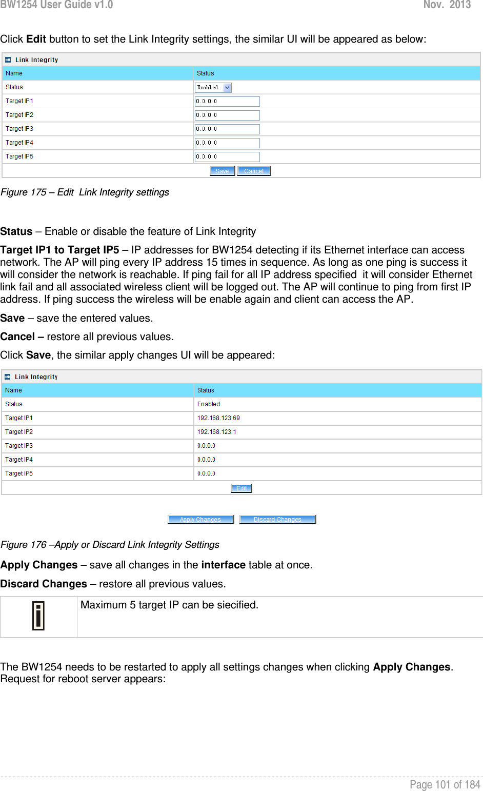
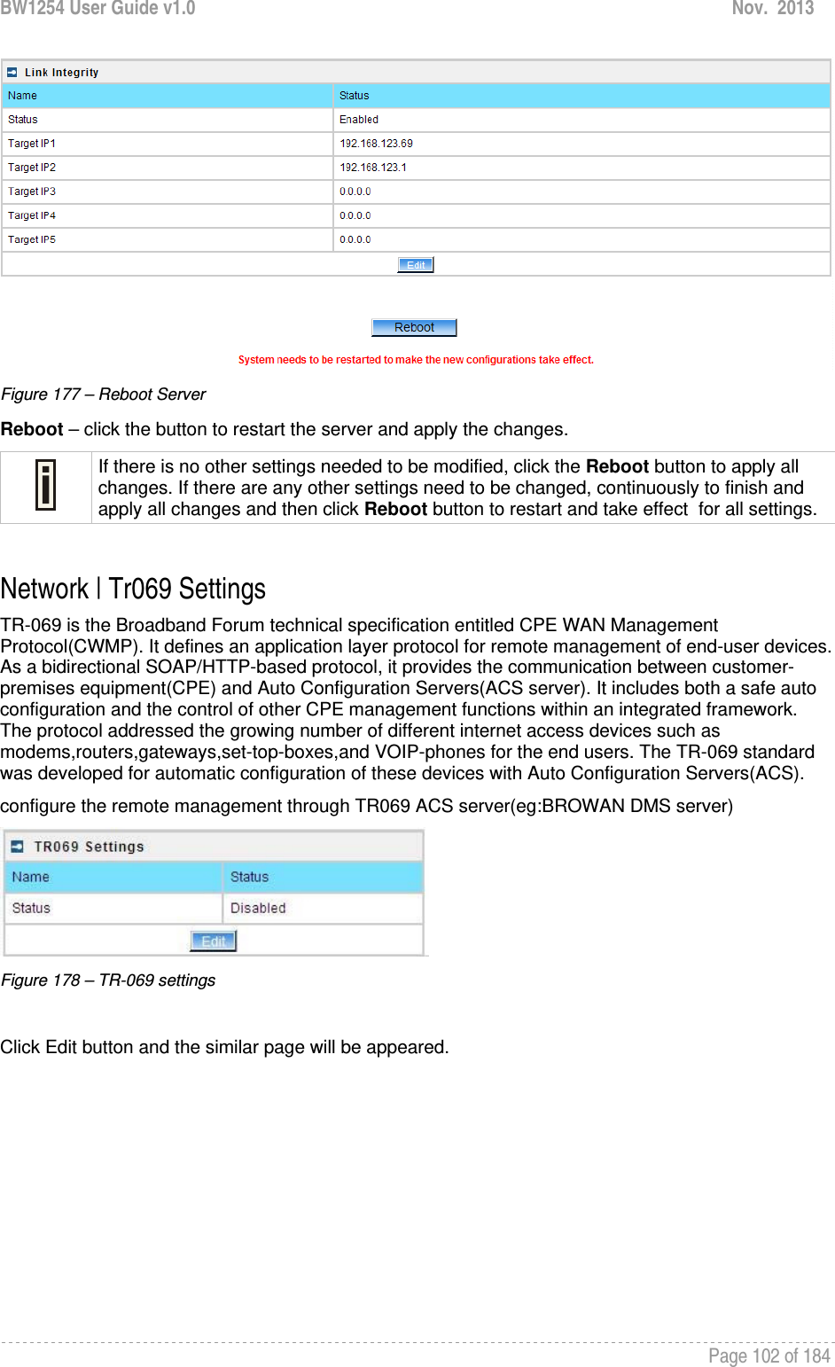
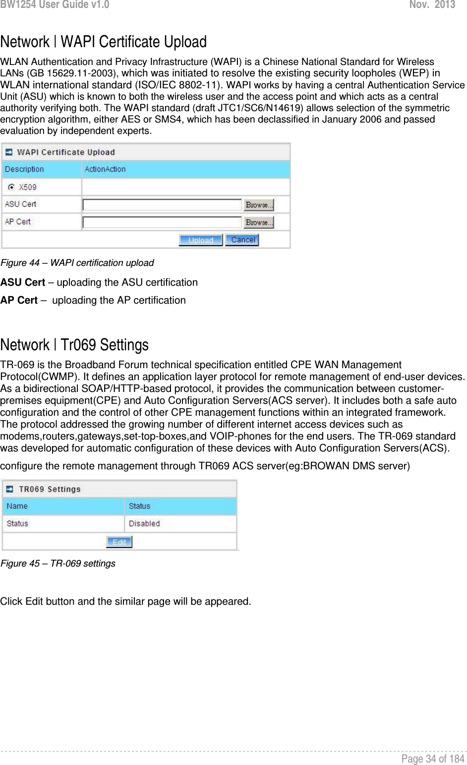
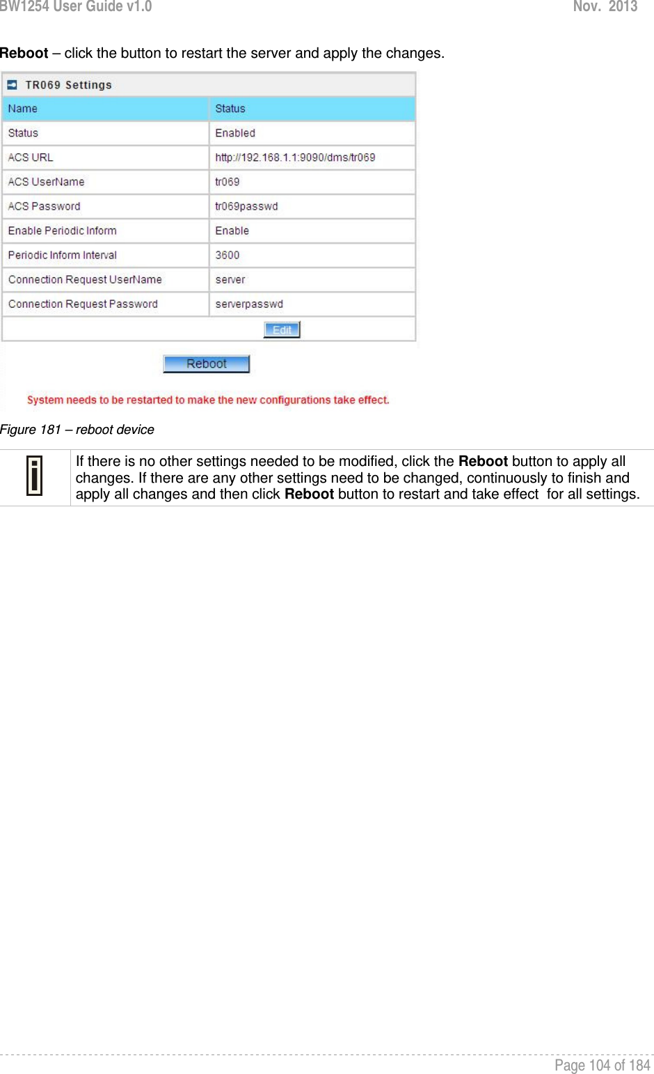
![BW1254 User Guide v1.0 Nov. 2013 Page 103 of 184 Figure 179 – edit TR-069 settings Status – enable or disable TR-069 setting.[enable/disable] ACS URL – enter the ACS server URL. ACS UserName – the user name for AP register to ACS server. ACS UserPassword – the password for AP register to ACS server. Enable Periodic Inform – when AP registered to the ACS server, it will automatically send inform message such as S/N,OUI,manufacturer and product name to the ACS server through TR-069 protocol in a periodic time. Periodic Inform Interval – the inform interval.[in seconds, the value is 720~4294967295] Connection Request UserName – when the ACS pulling a task to AP/CPE such as firmware upgrade/downgrade, AP need the user name to verify the task sending from ACS server. Connection Request Password –when the ACS pulling a task to AP/CPE such as firmware upgrade/downgrade, AP need the password to verify the task sending from ACS server. Contact the ACS server administrator to get the user name and password for Connection Request UserName and Connection Request Password otherwise the AP will not accept the task pulling by ACS server. After enter all field click save and apply changes button to take effect. Figure 180 – save TR-069 settings](https://usermanual.wiki/BROWAN-COMMUNICATIONS/1254XW.manual/User-Guide-2191248-Page-104.png)
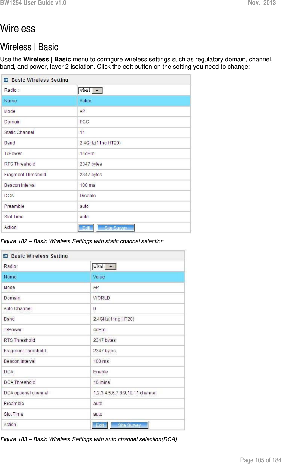
![BW1254 User Guide v1.0 Nov. 2013 Page 106 of 184 Radio – specify which wireless interface of BW1254 is shown. [wlan1(2.4G)/wlan2(5G)] Mode – show the radio operation mode. (AP mode or Bridge mode) Domain – show the regulatory domain Static Channel / Auto Channel – show the channel that the access point will use to transmit and receive information If DCA (Dynamic Channel Allocation) is enabled, this will show Auto Channel and its channel number is chosen in auto channel selection. If use static channel selection, this will show Static Channel and its channel number. DCA (Dynamic Channel Allocation) is useful feature to help choose the best channel automatically and reduce interference among many Access Points. Band – show the working bands on which the radio is working. wlan1:four bands listed: 2.4GHz(11g only) , 2.4GHz(11n HT20) , 2.4GHz(11n HT20/40plus), 2.4GHz(11n HT20/40minus) wlan2: four bands listed:5GHz(11a), 5GHz(11n HT20) , 5GHz(11n HT20/40plus), 5GHz(11n HT20/40minus) . By default, the HT20/40 is recommended. Tx Power – show the BW1254 transmission output power (without antenna gain) in dBm. RTS Threshold –the AP sends Request to Send(RTS) frames to a particular receiving station and negotiates the sending of a data frame. After receiving an RTS, the wireless station responds with a Clear to Send(CTS) frame to acknowledge the right to begin transmission. The default value is 2347.[recommend]. Fragment Threshold –It specifies the maximum size for a packet before data is fragmented into multiple packets. If you experience a high packet error rate, you may slightly increase the fragmentation threshold. Setting the fragmentation threshold too low may result in poor network performance. Only minor modifications of this value are recommended. The default value is 2347.[recommend] Beacon Interval –the Beacon Interval value indicates the frequency interval of the beacon. A beacon is a packet broadcast by the AP to synchronize the wireless network. DCA – Enable or Disable DCA service. DCA can help to choose the best working channel automatically. And static channel selection will be forbidden if DCA is enabled. DCA(Dynamic Channel Allocation) solution automatically select the optimal operational frequency channel when power up and periodically monitors the environment and adjusts for the best operational frequency channel. DCA threshold – specify the value (in minutes) of DCA threshold. This threshold is been used to judge if there is no wireless users connected during this time. And if yes, BW1254 will monitor the environment and adjust channel for the best operational one. If wireless network environment is stable which means auto channel selection needn’t do frequently, set a big value for DCA threshold to gain a stable wireless users’ connection. If wireless network environment changes continually, frequent auto channel selection is needed. So set a relative small value for DCA threshold to let channel change based on wireless environment.](https://usermanual.wiki/BROWAN-COMMUNICATIONS/1254XW.manual/User-Guide-2191248-Page-107.png)
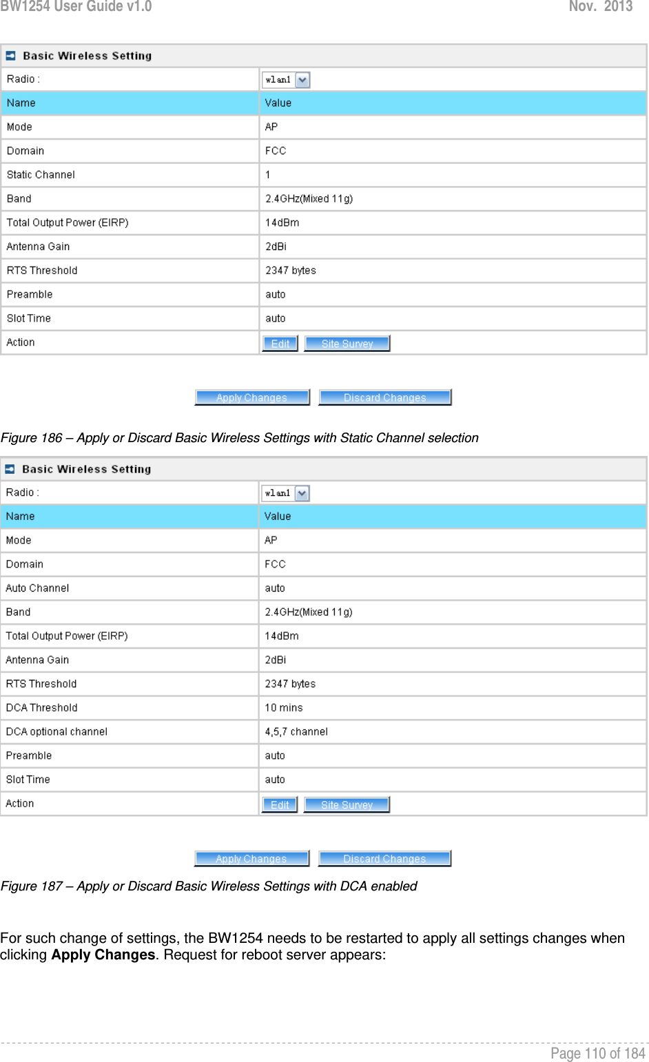
![BW1254 User Guide v1.0 Nov. 2013 Page 107 of 184 Wireless users’ will be kicked off when DCA is processing (new operational frequency channel takes effect). DCA optional channel – show the channels only in which auto channel selection (DCA) will be processed to reduce interference. Only when DCA is enabled, DCA threshold and DCA optional channel will be shown. Preamble – if your wireless device supports the short preamble and you are having trouble getting it to communicate with other 802.11b devices, make sure that it is set to use the long preamble. Auto: using long preamble when there are clients not supporting short preamble connected , otherwise using short preamble. The default is Auto.[recommend] Short: always using short preamble. Long: always using long preamble. Slot Time – show the slot time policy when working in 2.4GHz band. Auto: using long slot time when there are clients not supporting short slot time connected in, otherwise using short slot time. The Switching between long and short slot time is automatic. Short: always using short slot time. Long: always using long slot time. To Maximize the compatibility with some 11b clients, set both Preamble and Slot Time to long. Edit – edit the wireless basic settings To change basic wireless setting properties click the Edit button in the Action column. The status can be changed now: Figure 184 – Edit Basic Wireless Settings with static channel selection](https://usermanual.wiki/BROWAN-COMMUNICATIONS/1254XW.manual/User-Guide-2191248-Page-108.png)
![BW1254 User Guide v1.0 Nov. 2013 Page 108 of 184 Figure 185 – Edit Basic Wireless Settings with DCA enabled Radio Name – specify wireless interface of BW1254 is shown Mode – configure the radio operation mode. In AP-Router mode, the radio only support AP mode for wireless client connection.Domain – select the regulatory domain. Channel – select the channel that the access point will use to transmit and receive information. If one channel is defined, it acts as default channel. Channels list will vary depending on selected regulatory domain and selected band. If you wish to operate more than one access point in overlapping coverage areas, we recommend at least four channels interval between the chosen channels. For example, for three Access Points in close proximity choose channels 1, 6 and 11 for 11b/g or channels 36, 40 and 64 for 11a. Band – show the working bands on which the radio is working. wlan1:four bands listed: 2.4GHz(11g only) , 2.4GHz(11n HT20) , 2.4GHz(11n HT20/40plus), 2.4GHz(11n HT20/40minus) wlan2: four bands listed:5GHz(11a), 5GHz(11n HT20) , 5GHz(11n HT20/40plus), 5GHz(11n HT20/40minus) . TxPower – the BW1254 transmission output power in dBm. The value of the TxPower varies according to channel and regulatory domain. RTS Threshold – the AP sends Request to Send(RTS) frames to a particular receiving station and negotiates the sending of a data frame. After receiving an RTS, the wireless station responds with a Clear to Send(CTS) frame to acknowledge the right to begin transmission. The default value is 2347.[recommend]](https://usermanual.wiki/BROWAN-COMMUNICATIONS/1254XW.manual/User-Guide-2191248-Page-109.png)
![BW1254 User Guide v1.0 Nov. 2013 Page 109 of 184 Fragment Threshold – It specifies the maximum size for a packet before data is fragmented into multiple packets. If you experience a high packet error rate, you may slightly increase the fragmentation threshold. Setting the fragmentation threshold too low may result in poor network performance. Only minor modifications of this value are recommended. The default value is 2347.[recommend] Beacon Interval – the Beacon Interval value indicates the frequency interval of the beacon. A beacon is a packet broadcast by the AP to synchronize the wireless network. DCA – Enable or Disable DCA service. DCA can help to choose the best working channel automatically. And static channel selection will be forbidden if DCA is enabled. DCA(Dynamic Channel Allocation) solution automatically select the optimal operational frequency channel when power up and periodically monitors the environment and adjusts for the best operational frequency channel. DCA threshold – specify the value (in minutes) of DCA threshold. This threshold is been used to judge if there is no wireless users connected during this time. And if yes, BW1254 will monitor the environment and adjust channel for the best operational one. If wireless network environment is stable which means auto channel selection needn’t do frequently, set a big value for DCA threshold to gain a stable wireless users’ connection. If wireless network environment changes continually, frequent auto channel selection is needed. So set a relative small value for DCA threshold to let channel change based on wireless environment. Wireless users’ will be kicked off when DCA is processing (new operational frequency channel takes effect). DCA optional channel – specify the channels only in which auto channel selection (DCA) will choose for reducing interference reference. Only when DCA is enabled, DCA threshold and DCA optional channel will be shown. Preamble – if your wireless device supports the short preamble and you are having trouble getting it to communicate with other 802.11b devices, make sure that it is set to use the long preamble. Auto: using long preamble when there are clients not supporting short preamble connected , otherwise using short preamble. The default is Auto.[recommend] Short: always using short preamble. Long: always using long preamble. Slot Time – specify the slot time policy when working in 2.4GHz band. Auto: using long slot time when there are clients not supporting short slot time connection, otherwise using short slot time. The default is Auto.[recommend] Short: always using short slot time. Long: always using long slot time. To Maximize the compatibility with some 11b clients, set both Preamble and Slot Time to long. Change status or leave in the default state if no editing is necessary and click the Save button.](https://usermanual.wiki/BROWAN-COMMUNICATIONS/1254XW.manual/User-Guide-2191248-Page-110.png)
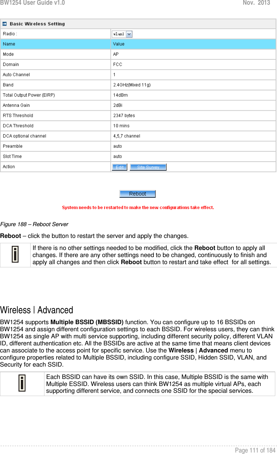
![BW1254 User Guide v1.0 Nov. 2013 Page 112 of 184 AP Mode If you configure AP mode, the page will be shown as below in Wireless | Advanced menu. Figure 189 – Advanced Wireless Setting (AP Mode) Radio – specify wireless interface to be configured. [wlan1(2.4G/wlan2(5G)] Mode – show the current operation mode of this radio (AP or Bridge) Interface – display the interface which corresponding to the SSID. Each Interface maps to a BSSID SSID – SSID name for wireless client searching and associating. Hidden – show the status of Hidden SSID feature[disable/enable] Security – show which security policy is used for this MBSSID entry Current Connect # – show the number of current wireless clients associate to this MBSSID New – create a new MBSSID entry Detail – show the detail information of this MBSSID entry Edit – edit the selected MBSSID entry you want to configure Delete – delete the selected MBSSID entry. When in AP mode, you can not delete the last entry Refresh – rescan the WEB page to get newer information Clicking New or Edit button to configure the SSID parameters. Describe as below:](https://usermanual.wiki/BROWAN-COMMUNICATIONS/1254XW.manual/User-Guide-2191248-Page-113.png)
![BW1254 User Guide v1.0 Nov. 2013 Page 113 of 184 Figure 190 – BSSID Setting -1 Radio – show the wireless interface is being configured. Interface – show the current sub-interface. Mode – show the operation mode of current radio. SSID – a unique ID for your wireless network. It is case sensitive and must not exceed 32 characters. The SSID is important for clients when connecting to the access point. Need Hidden SSID – when enabled, the SSID of this Interface is invisible in the networks list while scanning the available networks for wireless client (SSID is not broadcasted with its Beacons). When disabled, the AP’s SSID is visible in the available network list [enabled/disabled]. By default the Hidden SSID is disabled SSID status – activated or deactivated the SSID. The default is activated SSID[check box]. Disable 11b – enable/disable 11b client connection. [check box] to enable the function. Only 11n – only 802.11n client can connected to the SSID. Disassociation low MCS – low MCS client won’t associate to the AP. [check box] to enable it. Max Station Number – define maximum number of associated wireless client to this SSID. By default the number is maximum 127 client can be associated to the AP without check box. Or check box to enable limited client.[1~127] Layer 2 Isolation – Specify the layer 2 isolation policy. Enable Intra-BSS Layer 2 Isolation – when enabled, the clients that connect in this same BSS can’t visit each other. By default the intra-BSS layer 2 isolation is disabled. Intra-BSS layer2 isolation – which enable or disable client isolation under same SSID.Inter-BSS layer2 isolation – which enable or disable client isolation between different SSID. Please go to Wireless | Layer 2 Isolation(Inter-BSS) menu to configure inter-BSS layer 2 Isolation. Full layer 2 isolation need to set both intra-BSS and inter-BSS layer 2 isolation in the AP mode. Bandwidth – enable/disable upstream/downstream bandwidth control per SSID.](https://usermanual.wiki/BROWAN-COMMUNICATIONS/1254XW.manual/User-Guide-2191248-Page-114.png)
![BW1254 User Guide v1.0 Nov. 2013 Page 114 of 184 Download bandwidth – specified the maximum downstream in Mbps controlled by the SSID. Upload bandwidth – specify the maximum upstream in Mbps controlled by the SSID. Figure 191 – Multiple BSSID Setting -2 VLAN – specify VLAN policy Enable VLAN – when enabled, the outgoing packets from this SSID device will be tagged with VLAN ID and 802.1p tag. VLAN ID – configure VLAN ID for each Multiple SSID devices. Valid numbers are from 1 to 4094 802.1p Tag – configure 802.1p Tag for remote APC’s or Router’s QoS uses. Eight levels selective, Background(1), Spare(2), Best Effort(0), Excellent Effort(3), Controlled Load(4), Interactive Video(5), Interactive Voice(6), Network Contro(7) VLAN ID and 802.1p tag must cooperate with remote Router or APC. Interface priority – specify the traffic priority for this SSID interface, which is implemented according to 802.11e EDCA and makes sure the wireless downlink QoS. This priority is based on SSID, which means different BSSID can have different traffic priority and the traffic of the same SSID has the same priority This traffic priority only makes sure the priority of downlink (from AP to wireless client). 8 levels priorities are supplied. 1, 2, 0, 3, 4, 5, 6, 7 is from lowest priority to highest priority. And if no special QoS is needed, leave priority to default (0). 0 means Best Effort priority. WMM –BW1254 support WMM wireless clients and implement WMM QoS with the WMM clients. [enable] ESS in Tunnel – Settings for ESS in tunnel. When enabled, BW1254 setup tunnel with remote AC for passing through layer3 network. Remote Server IP – IP address of remote AC product that setup tunnel with BW1254](https://usermanual.wiki/BROWAN-COMMUNICATIONS/1254XW.manual/User-Guide-2191248-Page-115.png)
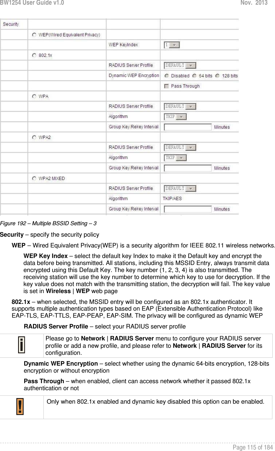
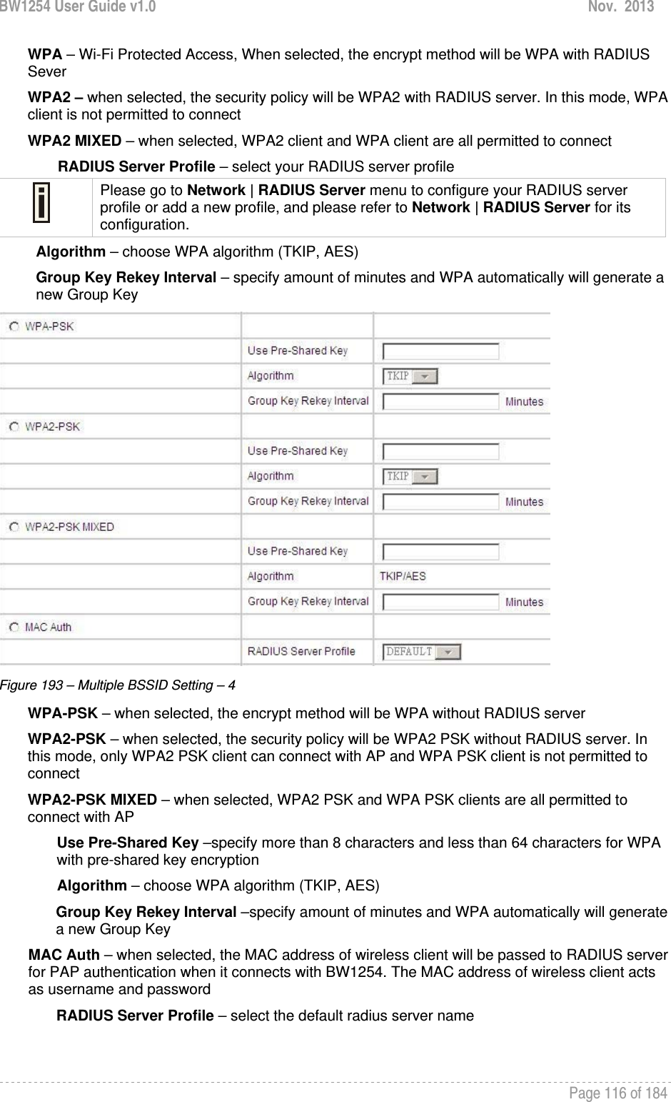
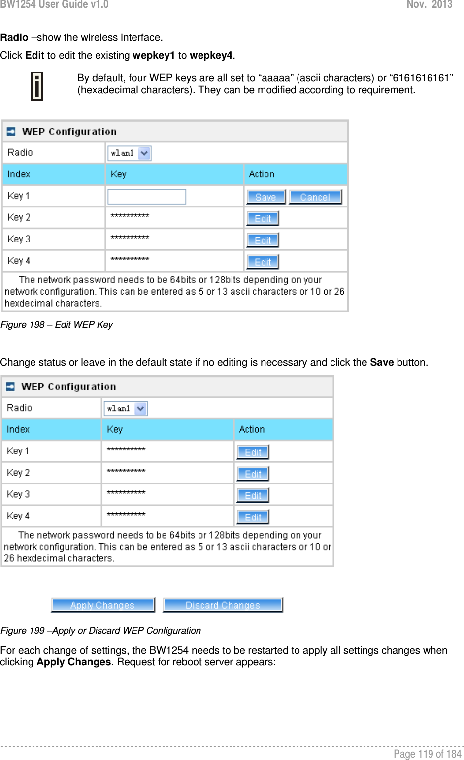
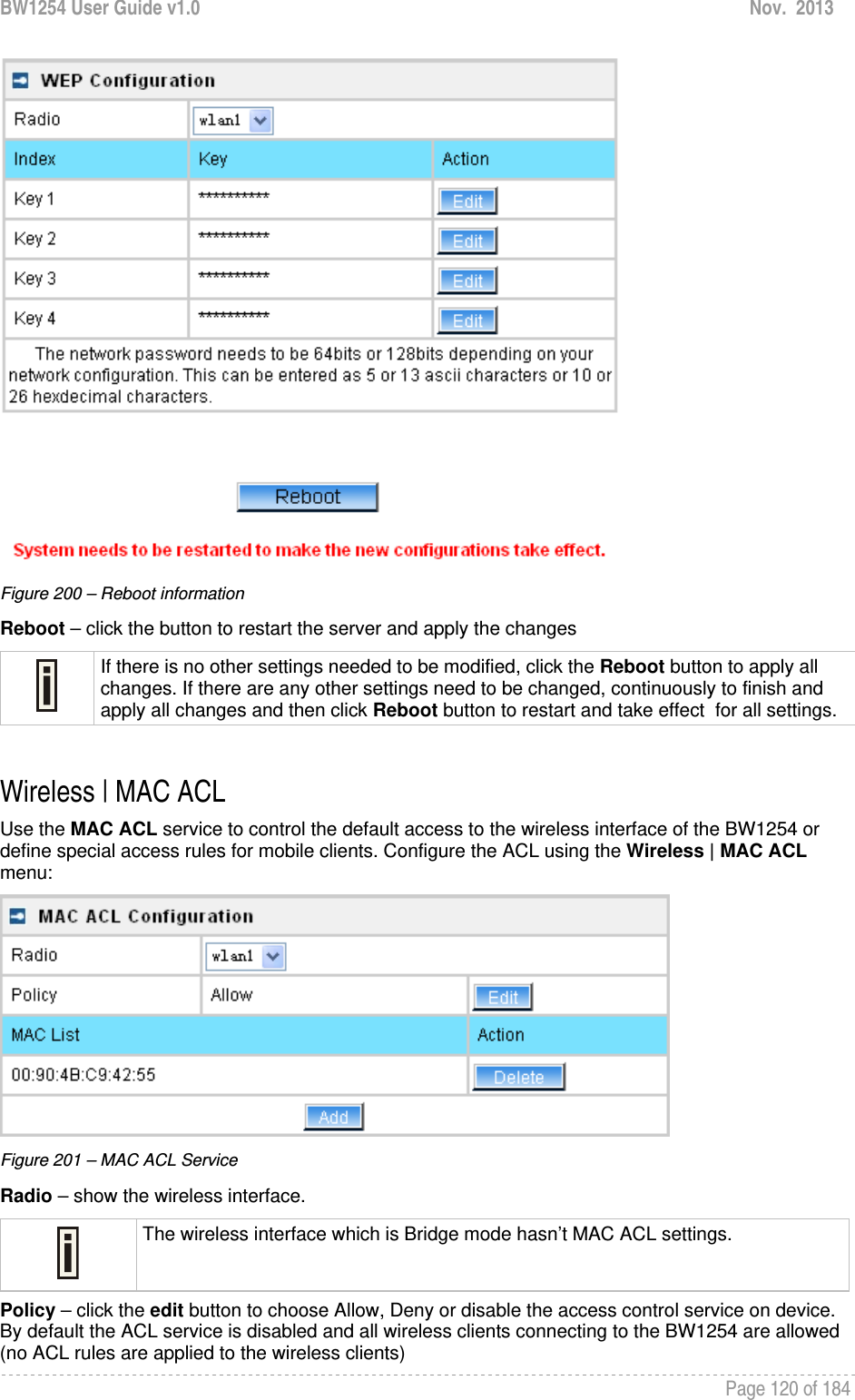
![BW1254 User Guide v1.0 Nov. 2013 Page 117 of 184 Figure 194 – Multiple BSSID Setting – 5 WAPI – WLAN Authentication and Privacy Infrastructure (WAPI) is a Chinese National Standard for wireless LAN(GB15629.11-2003).(Only for China) It needs to upload WAPI certificate. AAA Server Profile – select your RADIUS server profile WAPI-PSK –the encrypt method will be WAPI without RADIUS server Encode – Pre-shared key encode.[HEX/ASCII] Use Pre-Shared key – specify more than 8 characters and less than 64 characters for WPA with pre-shared key encryption Disabled – when selected, you don’t select any security policy Change status or leave in the default state if no editing is necessary and click the Save button. Figure 195 –Apply or Discard the advanced Settings in AP mode For each change of settings, the BW1254 needs to be restarted to apply all settings changes when clicking Apply Changes. Request for reboot server appears:](https://usermanual.wiki/BROWAN-COMMUNICATIONS/1254XW.manual/User-Guide-2191248-Page-118.png)
![BW1254 User Guide v1.0 Nov. 2013 Page 123 of 184 User User | Users The User | Users menu shows the statistics of connected users. The user can be monitored and managed such as drop from the network. Figure 206 – User’s statistics User – show the connected client’s MAC address Interface – show which BSS the client connected to User IP – IP address, from which the user’s connection is established [digits and dots] Authed – indicate this client is authenticated or not WEB Auth/L2 Auth – show the authentication method which user uses to connect Time Length – session duration since the user login [hh:mm:ss] Idle Time – amount of user inactivity time [hh:mm:ss] Action – view the statistics or kickoff the user. Detail – click on user details to get more information about the client: Kickoff – logout the user.](https://usermanual.wiki/BROWAN-COMMUNICATIONS/1254XW.manual/User-Guide-2191248-Page-124.png)
![BW1254 User Guide v1.0 Nov. 2013 Page 124 of 184 Figure 207 – User’s Details User – login user name interface – the interface that wireless client associated. User IP – the IP address of wireless client. MAC address – hardware address of the network device from which the user is connected WEB Auth/L2 Auth – show web authentication and layer2 authentication status, layer2 authentication include all supported EAP type of 802.1x auth and MAC auth WISP – WISP domain name where the user belongs Session ID – the unique user’s session ID number. This can be used for troubleshooting purposes Remaining Time Length – remaining user’s session time [hh:mm:ss]. Session time for user is defined in the RADIUS Server Idle time – specify current idle time. Idle Timeout – specify the time of user idle timout [hh:mm:ss]. When reach the time, the user will be logged out automatically.](https://usermanual.wiki/BROWAN-COMMUNICATIONS/1254XW.manual/User-Guide-2191248-Page-125.png)
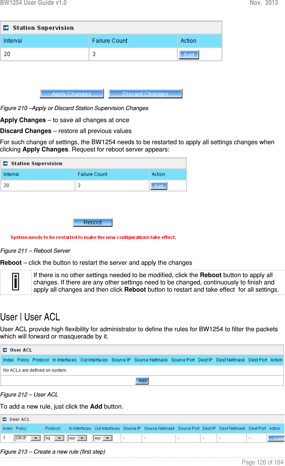
![BW1254 User Guide v1.0 Nov. 2013 Page 125 of 184 Input Bytes – amount of data in bytes which the user network device has received [Bytes] Output Bytes – amount of data in bytes, transmitted by the user network device [Bytes] Remaining Input/Output Bytes – user session remaining input/output bytes. WISPr Operator can define the user session in bytes. Remaining bytes is received from RADIUS [Bytes/unlimited] Remaining Total Bytes –user session remaining total bytes. WISPr Operator can define the user session in bytes. Remaining bytes is received from RADIUS [Bytes/unlimited] Bandwidth Downstream/Upstream – user upstream and downstream bandwidth [in bps] Back – returns to connect client’s statistics list Kickoff – click this button to logout the user from access point. Refresh – click the button to refresh users’ statistics User | Station Supervision The Station Supervision function is used to monitor the connected host station availability. This monitoring is performed with ping. If the specified number of ping failures is reached (failure count), the user is logged out from the BW1254. Figure 208 – Station Supervision To adjust the ping interval/failure count, click the Edit button. Figure 209 – Edit Station Supervision Interval – define interval of sending ping to host [in seconds] Failure Count – failure count value after which the user is logged out from the system Save – save station supervision settings Cancel – cancel changes Change status or leave in the default state if no editing is necessary and click the Save button.](https://usermanual.wiki/BROWAN-COMMUNICATIONS/1254XW.manual/User-Guide-2191248-Page-126.png)
![BW1254 User Guide v1.0 Nov. 2013 Page 127 of 184 First step select the rule policy [drop/accept/masquerade] to deal with packet and the packet type [all/TCP/UDP/ICMP] and which interface the rule will act on. Policy – define the policy of client through the access point. It supports three types of rules: DROP, ACCEPT and MASQUERADE. The appropriate policy defines what to do if the data packet received matches the rule Protocol – network protocol which the rule affects. Can be specified as one of “TCP/UDP/ICMP” or “any” In Interface – the data packet to the current interface must obey the rule Out Interface – the data packet from the current interface must obey the rule Figure 214 – Create a new rule (second step) Second step select the type of source IP and destination IP [special IP/any IP]. Figure 215 – Create a new rule (third step) Third step choose the type of source port and destination port [any port/special port]. Figure 216 – Create a new rule (fourth step) Fourth step, fill out the source IP address and destination IP address (including IP address and net mask, if you choose “any IP” in second step, you need not fill out the IP address); fill out the source port and destination port (if you select any port in third step or select protocol ICMP/all, you need not fill out the port). Figure 217 – Create a new rule (fifth step) After complete the rule configuration, click the “apply changes” button to save your configuration. You can also re-order your rules if you have many rules configured and arrange the priority of them. The rule with index 1 has the highest priority; with index 2 has the second high priority and so on. Figure 218 – re-order rules Click Edit Sort button of one rule to re-order its priority and then select the index number, click Save button to save your changes.](https://usermanual.wiki/BROWAN-COMMUNICATIONS/1254XW.manual/User-Guide-2191248-Page-128.png)
![BW1254 User Guide v1.0 Nov. 2013 Page 128 of 184 Figure 219 –Apply or Discard User ACL Changes Apply Changes – to save all changes of User ACL at once Discard Changes – restore all previous values Please be careful to use the DROP policy. For example, if DROP tcp for any source IP, BW1254 web UI will not be accessed. User | Walled Garden The walled garden is an environment that controls the user's access to Web content and services. It is to define a free, restricted service set for a user do not logged into the system. Use the User | walled garden menu to view or change the free URLs or hosts: Figure 220 –Walled Garden New URL – click the new URL button and enter the new URL and its description. Save entered information by clicking the update button: Figure 221 – Add New URL part 1 URL for User – define full URL address. Ex:[http://www.test.com] String to Display – site description visible to user listed on the welcome and login page:](https://usermanual.wiki/BROWAN-COMMUNICATIONS/1254XW.manual/User-Guide-2191248-Page-129.png)
![BW1254 User Guide v1.0 Nov. 2013 Page 129 of 184 Figure 222 – Walled Garden link in the Welcome Page New Host – If you need to define hosts (web servers) for walled garden, specify hosts by clicking the new host button and click the update button: Figure 223 – Walled Garden Host Type –select the data traffic protocol for host server [TCP/UDP]. Host – Web server address [IP address or host name]. Netmask – enter the network mask to specify the host servers network. Port – network port, which is used to reach the host [1-65535]. For standard protocols use the default ports: Protocol Port HTTP 80 HTTPS 443 FTP 21 User | WISP Different WISPs (Wireless Internet Service Providers) can be associated with appropriate RADIUS servers and device interfaces using the User | WISP menu: Figure 224 – WISP Menu Domain policy means BW1254 use which policy to fetch WISP name from user name then to judge user belong which domain.](https://usermanual.wiki/BROWAN-COMMUNICATIONS/1254XW.manual/User-Guide-2191248-Page-130.png)
![BW1254 User Guide v1.0 Nov. 2013 Page 130 of 184 Up to 32 WISP entries can be defined using the User | WISP menu. The owner can use three policies to judge the WISP name from user name: 1. username follow the format: username@WISPdomain 2. username follow the format: WISPdomain/username 3. use prefix of username as wisp name, the range of prefix length is from 2 to 6 Figure 225 – Domain Policy Add WISP – click to define WISP for RADIUS server Figure 226 – Define New WISP Name – new WISP domain name [string, up to 256 symbols, no space, dot or dash allowed] RADIUS Name – select RADIUS for new WISP from list box [non editable] Save – click the button to save the new WISP Cancel – restore all previous values Figure 227 – Apply or Discard Changes of WISP settings BW1254 needs to be restarted to apply all settings changes when clicking Apply Changes. Request for reboot server appears:](https://usermanual.wiki/BROWAN-COMMUNICATIONS/1254XW.manual/User-Guide-2191248-Page-131.png)
![BW1254 User Guide v1.0 Nov. 2013 Page 131 of 184 Figure 228 – Reboot information Reboot – click the button to restart the server and apply the changes. If there is no other settings needed to be modified, click the Reboot button to apply all changes. If there are any other settings need to be changed, continuously to finish and apply all changes and then click Reboot button to restart and take effect for all settings. User | Start Page The start page is the default web page where users will be redirected after log-on. This value will be overwritten by the WISP RADIUS attribute no.4 “Redirection-URL” if provided in the authentication response message. Use the User | Start Page menu to view or change the start page URL: Figure 229 – Start Page The administrator can change the start page by clicking the Edit button. The value entry field will change into an editable field: Figure 230 – Edit Start Page Value – enter new redirection URL of start page in valid format [http://www.startpageurl.com] Save –click the button to save new settings Cancel – restores all previous values](https://usermanual.wiki/BROWAN-COMMUNICATIONS/1254XW.manual/User-Guide-2191248-Page-132.png)
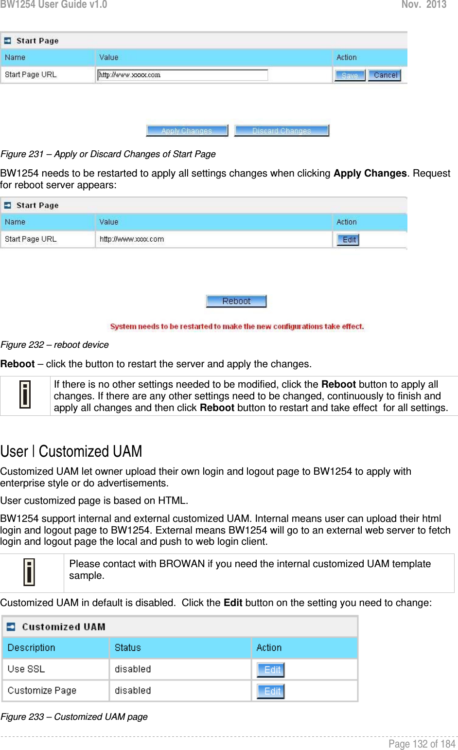
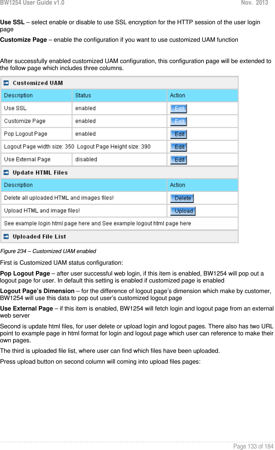
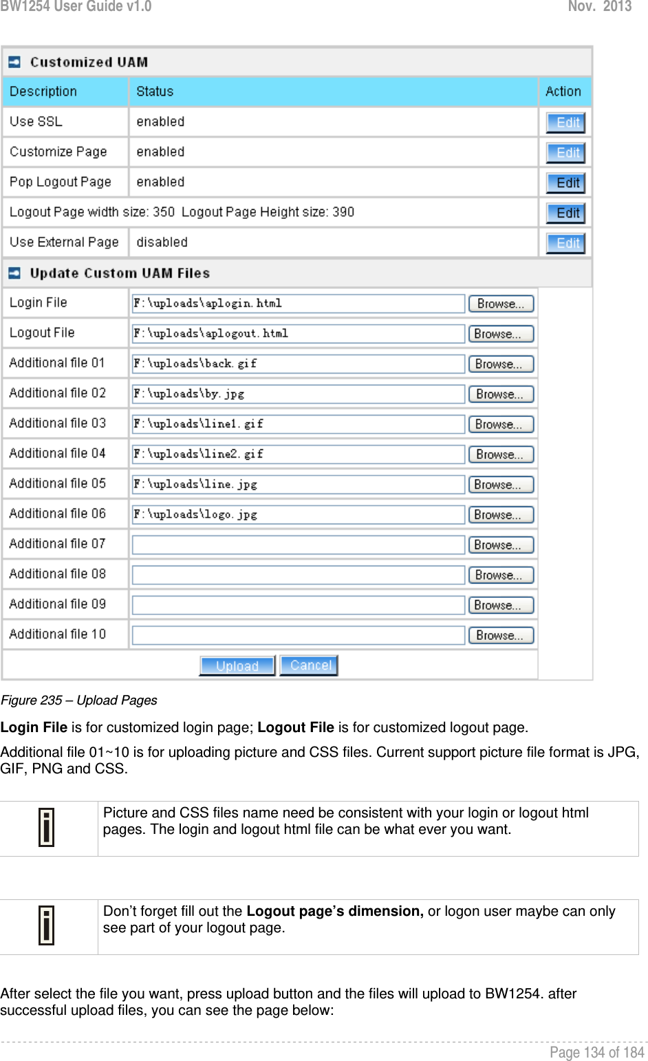
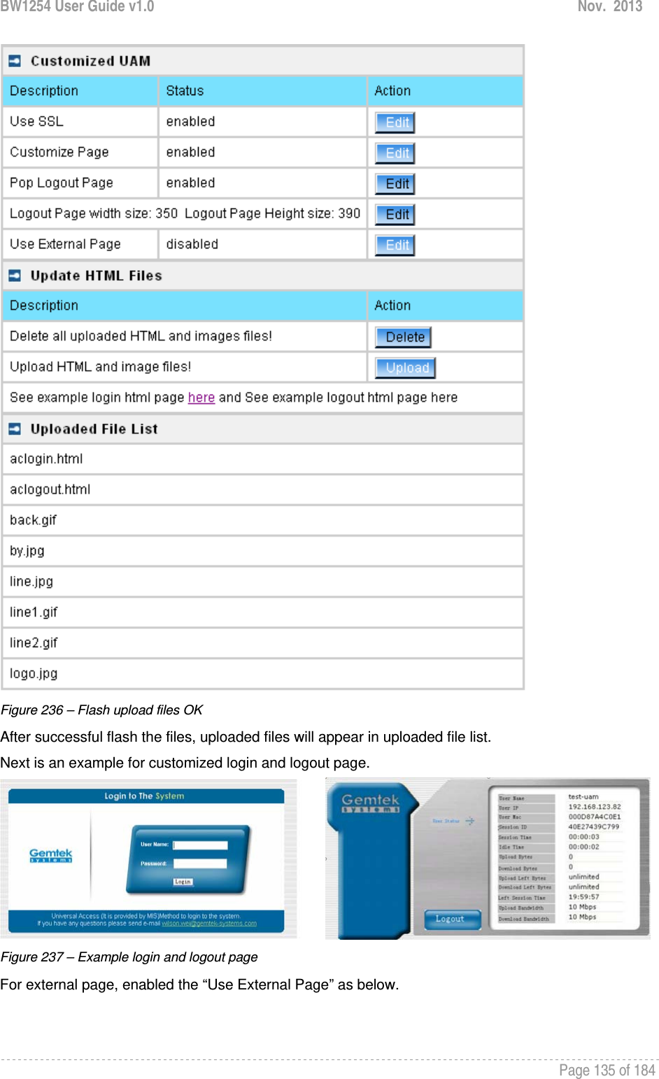
![BW1254 User Guide v1.0 Nov. 2013 Page 136 of 184 Figure 238 – External Page Configuration Fill out the external login page and external logout page [http://host IP address:port/path]. BW1254 would auto-update the external page every 7200 seconds or you change the interval update time. External page example will be found in the links under the last line. User | Pages Detailed description about user page customization is given in the Chapter 5 – User Pages. The welcome/login/logout/help pages can be easily changed to user defined pages by choosing the edit menu. The pages configuration menu is displayed by default: In External page mode, BW1254 will only fetch the login and logout html page to local, the picture or the CSS file which link on the customized login/logout page will not be fetch. So the link to the picture and CSS file on user customized html file need to be an absolute address which point to the external web server. BW1254 would use the default login or logout page if user did not upload the customized pages or BW1254 did not get the external page from the external login/logout page IP.](https://usermanual.wiki/BROWAN-COMMUNICATIONS/1254XW.manual/User-Guide-2191248-Page-137.png)
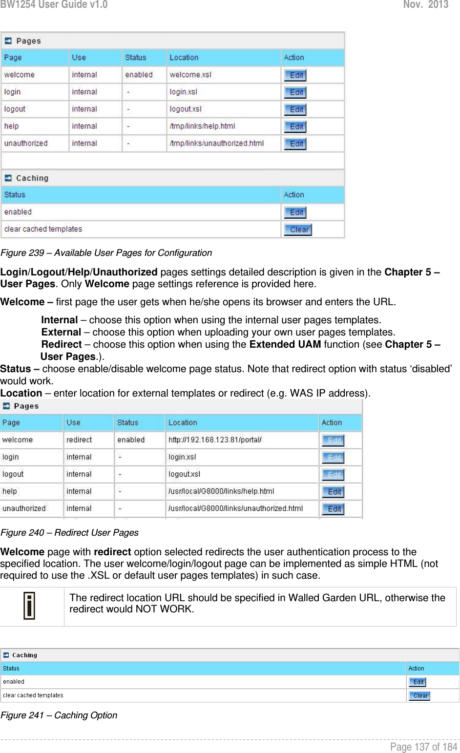
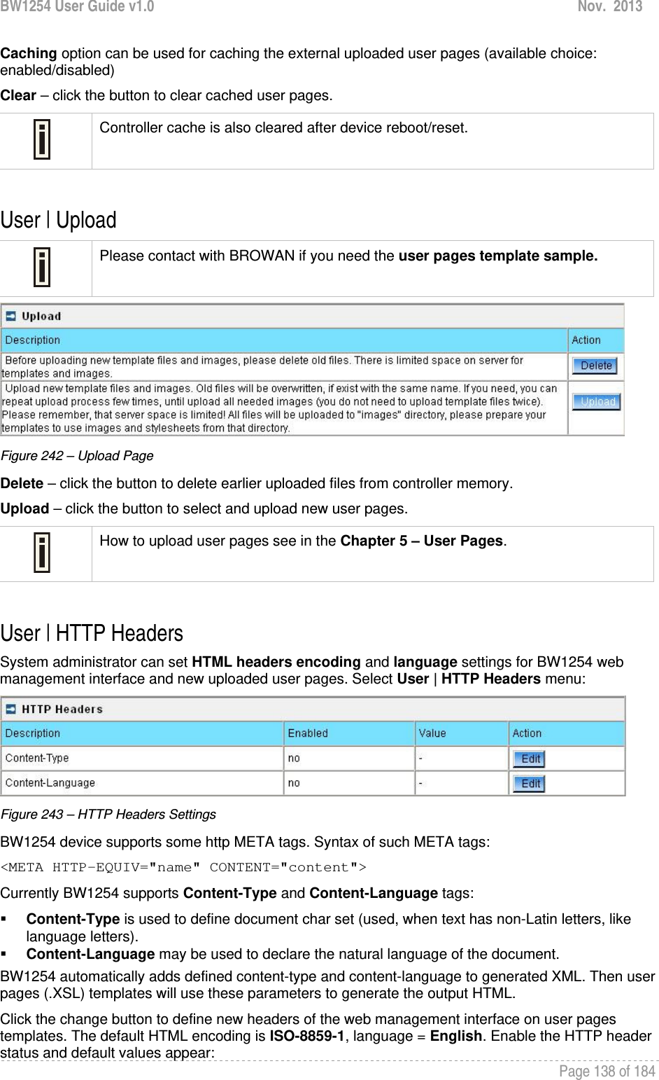
![BW1254 User Guide v1.0 Nov. 2013 Page 139 of 184 Figure 244 – Set HTTP Headers The system administrator can set his own header encoding and language settings. Use the HTML 4.01 specification to define the header encoding and language. User | Remote Authentication Read more about the extended UAM feature in Chapter 5 – User Pages, section: Extended UAM The Remote Authentication feature under the User menu allows an external Web Application Server (WAS) to intercept/take part in the user authentication process, and to log on and log off users externally. It provides a means to query user session information as well. By default such remote authentication is disabled: Figure 245 – Remote Authentication Click the edit button next to appropriate settings to specify remote authentication parameters: Figure 246 – Enable Remote Authentication Remote Authentication – select status: [enabled/disabled]. Shared Secret – enter password for WAS to communicate with AC [sting (4-32), no spaces allowed]. The shared secret must match that configured on the WAS. This shared secret allows the WAS to initiate a secure (SSL) command session with the BW1254 to pass login commands.](https://usermanual.wiki/BROWAN-COMMUNICATIONS/1254XW.manual/User-Guide-2191248-Page-140.png)
![BW1254 User Guide v1.0 Nov. 2013 Page 140 of 184 Services Services | Telnet Use Services | Telnet menu to manage the telnet/SSH service of your BW1254. Figure 247 – System Configuration settings Telnet Service – Enable or disable telnet service of BW1254 SSH Service – Enable or disable SSH service of BW1254 The default of these two services are all Enabled. The current IETF SSH (SSHv2) is supported for security of accessing BW1254 via telnet/CLISH. Services | SNMP SNMP is the standard protocol that regulates network management over the Internet. To communicate with SNMP manager you must set up the same SNMP communities and identifiers on both ends: manager and agent. Use the Services | SNMP menu to change current SNMP configuration. Figure 248 – SNMP settings Readonly community – community name is used in SNMP version 1 and version 2c. Read-only (public) community allows reading values, but denies any attempt to change values [1-32 all ASCII printable characters, no spaces] Readwrite community – community name is used in SNMP version 1 and version 2c. Read-write (private) community allows to read and (where possible) change values [1-32 all ASCII printable characters, no spaces] Default Trap community – the default SNMP community name used for traps without specified communities. The default community by most systems is "public". The community string must match the community string used by the SNMP network management system (NMS) [1-32 all ASCII printable characters, no spaces]](https://usermanual.wiki/BROWAN-COMMUNICATIONS/1254XW.manual/User-Guide-2191248-Page-141.png)
![BW1254 User Guide v1.0 Nov. 2013 Page 141 of 184 HeartBeat Trap Interval – define the interval that AP send trap information to the server.[in seconds] Trap Configuration Table: You can configure your SNMP agent to send SNMP Traps (and/or inform notifications) under the defined host (SNMP manager) and community name (optional). Figure 249 – SNMP Trap table settings Click Add to add a new SNMP manager or Delete to delete a specific SNMP manager. Clicking Add: Figure 250 – Add SNMP Trap Host IP – enter SNMP manager IP address [dots and digits] Host Port – enter the port number the trap messages should be send through [number] Trap Type – select trap message type [v1/v2/inform] Community – specify the community name at a SNMP trap message. This community will be used in trap messages to authenticate the SNMP manager. If not defined, the default trap community name will be used (specified in the SNMP table) [1-32 all ASCII printable characters, no spaces] Save – save all current settings Cancel – restore the last settings Services | NTP NTP (Network Time Protocol) is used to synchronize the system time with the selected network NTP server. Use the Services | NTP menu to configure the NTP service: Figure 251 – NTP Settings](https://usermanual.wiki/BROWAN-COMMUNICATIONS/1254XW.manual/User-Guide-2191248-Page-142.png)
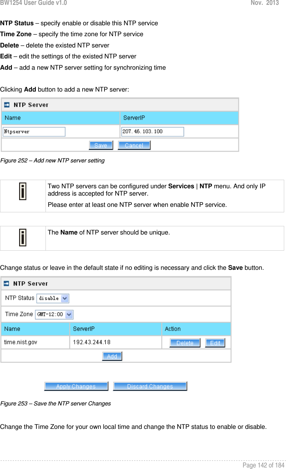
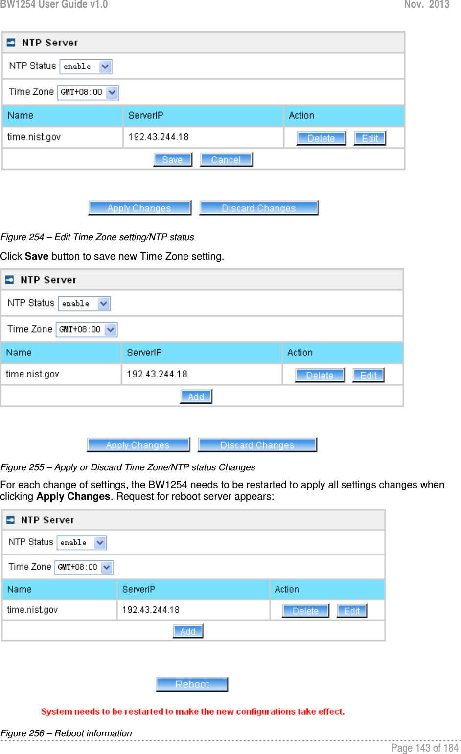
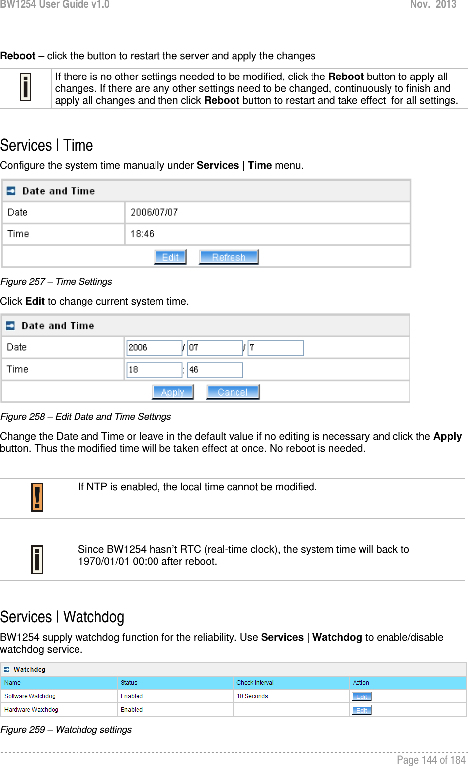
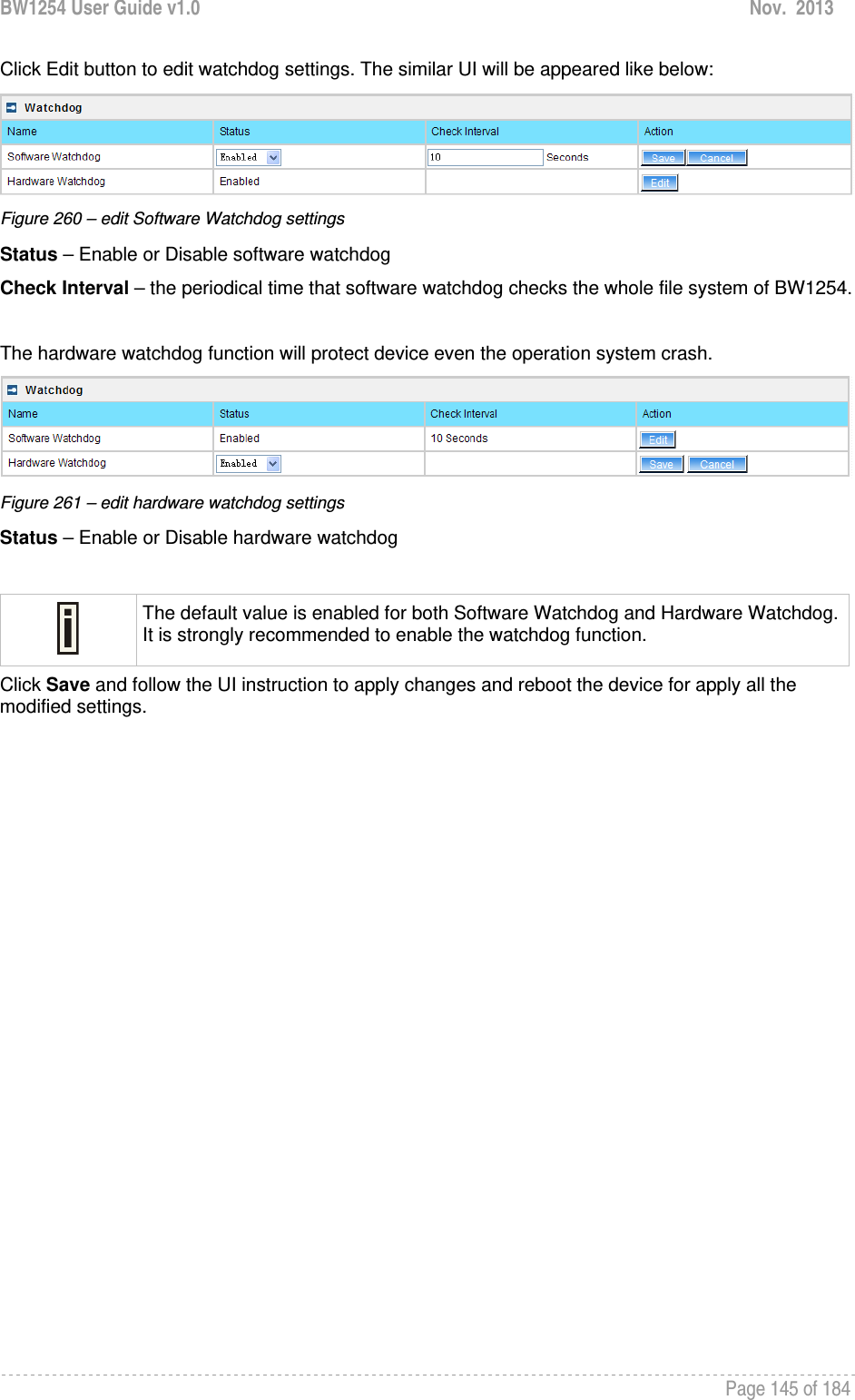
![BW1254 User Guide v1.0 Nov. 2013 Page 146 of 184 System System | Administrator The System | Administrator menu is for changing the administrator’s settings: username and password: Figure 262 – system security settings User Name – administrator username for access to BW1254 (e.g. web interface, CLI mode) [1-32 symbols, spaces not allowed] Old Password – old password value New Password – new password value used for user authentication in the system [4-8 characters, spaces not allowed] Confirm Password – re-enter the new password to verify its accuracy Save – click to save new administrator settings. Default administrator logon settings are: User Name: admin Password: admin01 Password length is from 4 to 8 characters. After filling in the right Old password and the New Password, clicking the Save button for taking effect immediately. After clicking Save button, the below UI will be shown to notify that the new password setting has been taken place: Figure 263 – system security settings save and take effect successfully](https://usermanual.wiki/BROWAN-COMMUNICATIONS/1254XW.manual/User-Guide-2191248-Page-147.png)
![BW1254 User Guide v1.0 Nov. 2013 Page 147 of 184 System | System Log Use the System | System Log menu to trace your AP system processes and get the system log locally or on the remote log server. Figure 264 – System Log settings To enable the System Log remote sending function, click the Edit button on the Remote System Log table and choose the enabled option: Figure 265 – Configure Remote System Log Utility Remote Log Status – choose disable/enable remote log [enabled/disabled] Host IP – specify the host IP address where to send the System Log messages [dots and digits] Log Level – specify the remote log message level you want to trace [critical, error, warning, info and debug] Do not output “debug” log unless there are important issue needs to be clarified. Debug log will output all of the information so that it will severely drop down the network performance. BW1254 support standard sys. log server. Save – save changes Cancel – restore the previous values To view the System Log locally, click the Edit button on the Local System Log table and choose the enabled option: Figure 266 – Configure Local System Log](https://usermanual.wiki/BROWAN-COMMUNICATIONS/1254XW.manual/User-Guide-2191248-Page-148.png)
![BW1254 User Guide v1.0 Nov. 2013 Page 148 of 184 Local Log Status – choose disable/enable local log [enabled/disabled] Log Limit – specify the maximum length of local log message in byte [20000-512000] Log Level – specify the local log message level you want to trace [critical, error, warning, info and debug] Save – save changes Cancel – restore the previous values View – view the log messages locally Click View button, a similar screen will appear as below: Figure 267 – View Local Log Messages Clear – clear current log message Refresh – get the updated log messages Return – back to System Log page System | System Mode In this page, you can select the system mode of your BW1254. Figure 268 – System Mode Settings](https://usermanual.wiki/BROWAN-COMMUNICATIONS/1254XW.manual/User-Guide-2191248-Page-149.png)
![BW1254 User Guide v1.0 Nov. 2013 Page 149 of 184 Mode – select whether the system mode of BW1254 is AP mode or AP Router mode IP – specify the IP address of current interface [dots and digits] Netmask – specify the subnet mask of current interface [dots and digits] Gateway – specify the gateway to other networks Protocol – specify static for setting IP address manually and dhcp for getting IP address dynamically acting as DHCP client Apply and Reboot – click the button to restart the device and apply all setting changes The Web Interface in AP-Router mode is different from that in AP mode. For the detailed configuration of BW1254 working in AP mode, please refer to: Chapter 3 – Reference Manual----AP Mode System | System Info Administrator can self-define the device information including the system name, system location and system contact information of his BW1254. Figure 269 – System info Settings System Name –edit the system name, the column length range is 1 to 255. Figure 270 –edit the system name System Location – edit the system location, the column length range is 1 to 255. Figure 271 –edit the system laocation System Contact – edit the system contact, the column length range is 1 to 255.](https://usermanual.wiki/BROWAN-COMMUNICATIONS/1254XW.manual/User-Guide-2191248-Page-150.png)
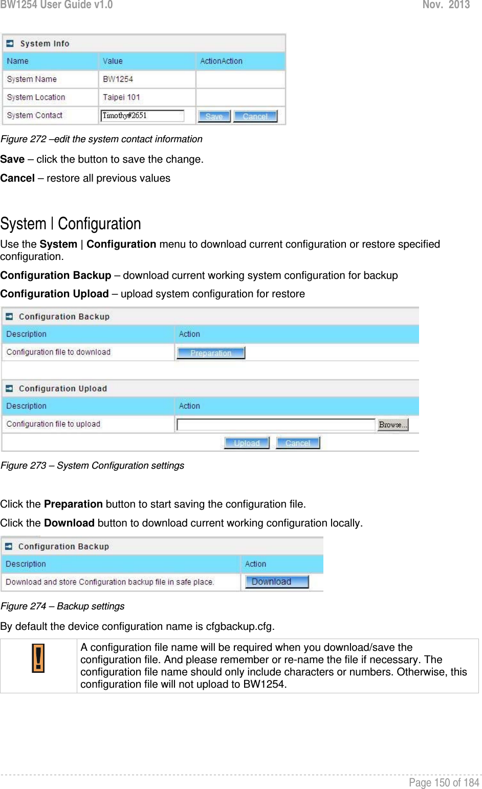
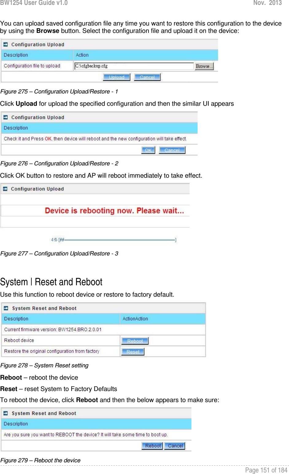
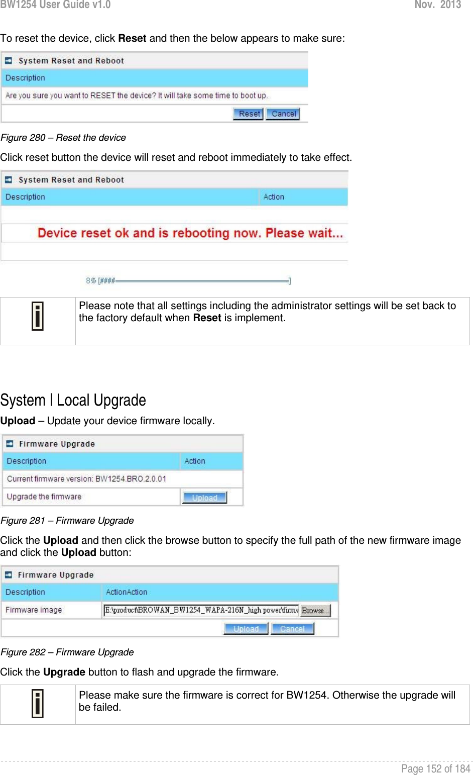
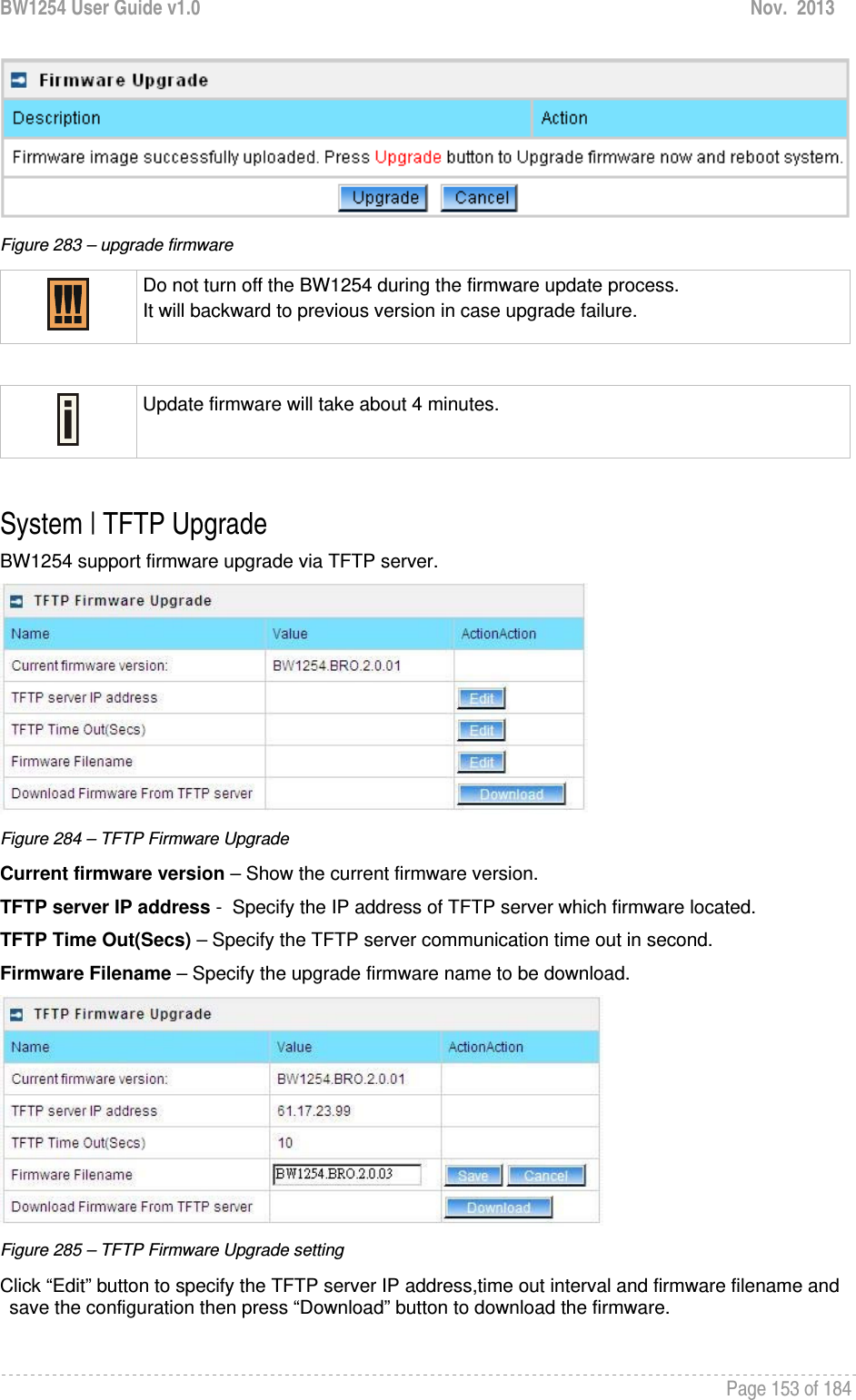
![BW1254 User Guide v1.0 Nov. 2013 Page 154 of 184 Please make sure the firmware is correct for BW1254. Otherwise the upgrade will be failed. Do not turn off the BW1254 during the firmware update process. It will backward to previous version in case upgrade failure. System | Location Settings You can define the longitude and latitude for the device information or for the NMS to locate the device location. Figure 286 – location setting Click edit to enter the Longitude and Latitude in digit and dot format. Figure 287 – edit location[longitude/latitude] Click save button to save it.](https://usermanual.wiki/BROWAN-COMMUNICATIONS/1254XW.manual/User-Guide-2191248-Page-155.png)
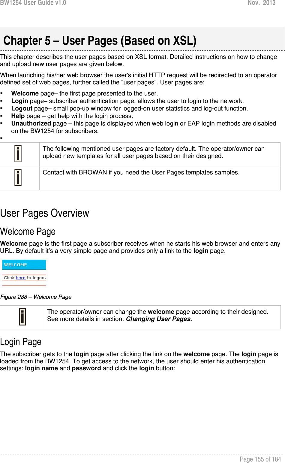
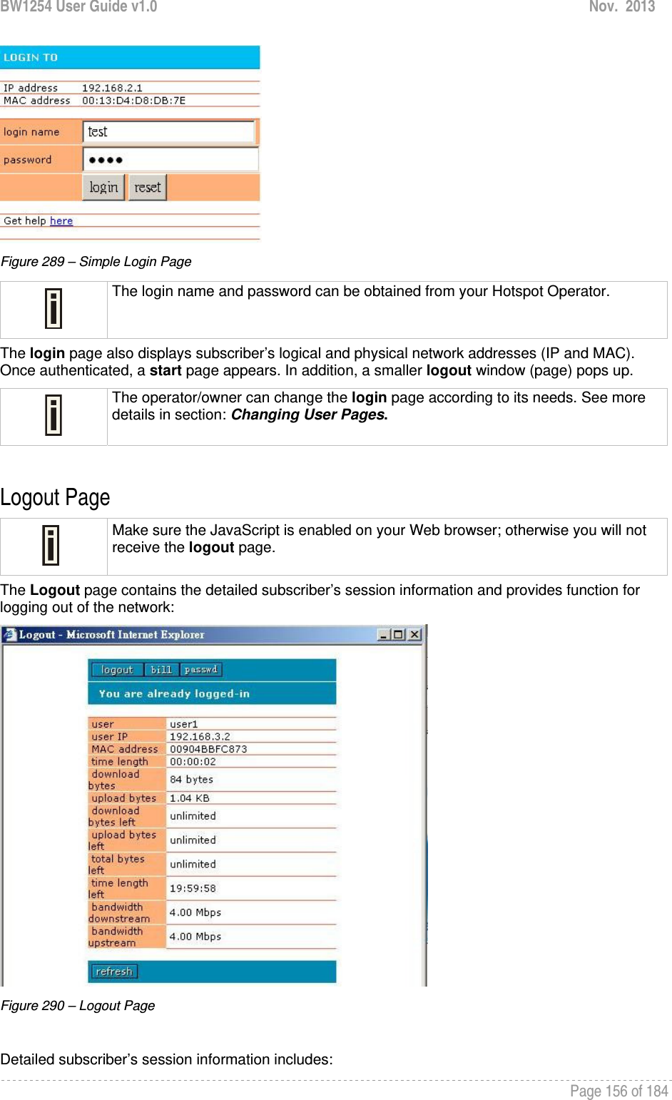
![BW1254 User Guide v1.0 Nov. 2013 Page 157 of 184 Logout button – click the button to logout from the network. The log-out pop-up window closes. Bill button – display subscriber’s billing information (not include current session). Passwd button – click the button to change subscriber’s password. User – subscriber’s login name. User IP – subscriber’s logical network name (IP address). MAC Address – subscriber’s physical network address. time length– subscriber’s time length from client log on in format: [hours: minutes: seconds]. Download/upload bytes – subscriber’s session download and upload statistics in bytes. Download/upload bytes left – session download and upload bytes left for subscriber limited from RADIUS [in B, KB, MB, GB and unlimited]. Total bytes left – session total (download and upload) bytes left for subscriber limited form RADIUS [in B, KB, MB, GB and unlimited]. time length left – time length left in format: [hours: minutes: seconds]. Bandwidth downstream/upstream – available upstream and downstream bandwidth for subscriber limited from RADIUS [in bps]. Refresh button – click the button to refresh the subscriber session information. The operator/owner can change the logout page interface according to its needs. See more details in section: Changing User Pages.. All session details are further accessible via the operator XML interface. Help Page Figure 291 – Get help page Click on the get help link in the login page for help tips related to network registration. A page appears similar to the following: Figure 292 – Get help page The operator/owner can change the help page according to its needs. See more details in section: Changing User Pages.](https://usermanual.wiki/BROWAN-COMMUNICATIONS/1254XW.manual/User-Guide-2191248-Page-158.png)