BTE Technologies DAQRETROFIT Strength measurement equipment. User Manual 40050053 rev A
BTE Technologies, Inc. Strength measurement equipment. 40050053 rev A
UserManual.wiki
>
BTE Technologies
>
DAQRETROFIT User Manual
>
Users Manual 1
Contents
1.
FCC Manual Addendum
2.
Users Manual 1
3.
Users Manual 2
Users Manual 1
Navigation menu
Upload a User Manual
Namespaces
Wiki Guide
HTML
PDF
Info
Views
User Manual
Discussion / Help
Navigation


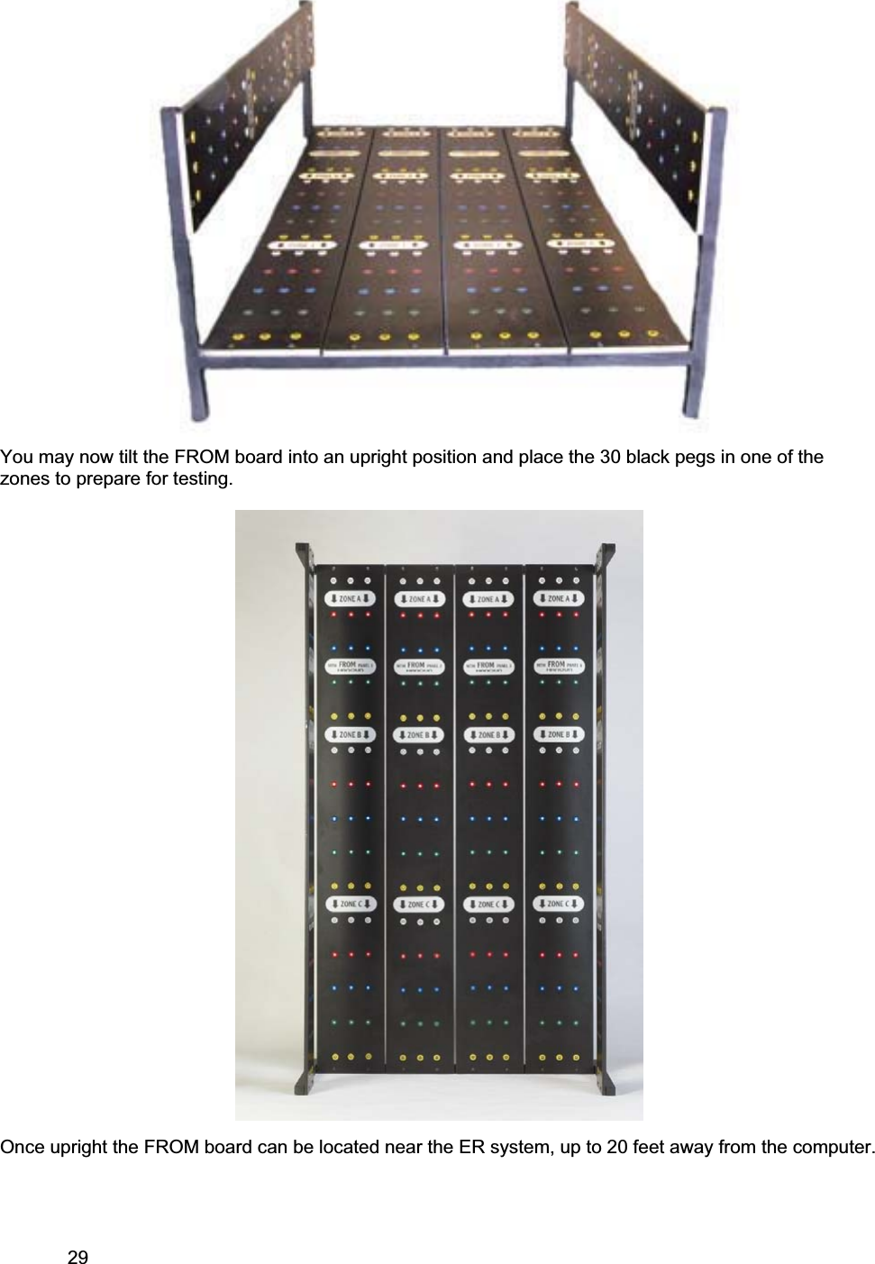

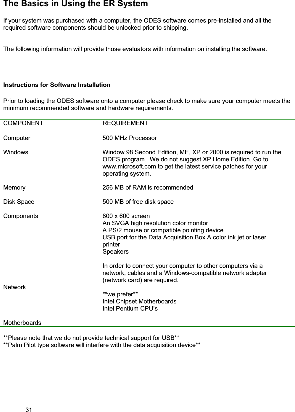
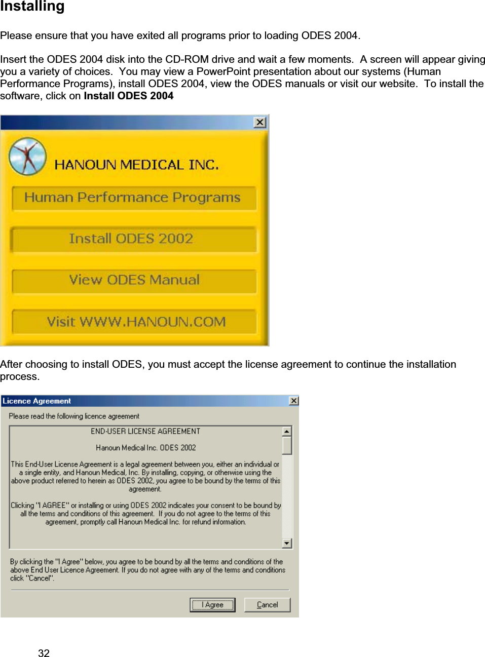
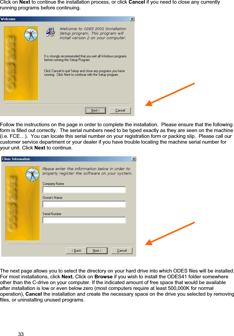
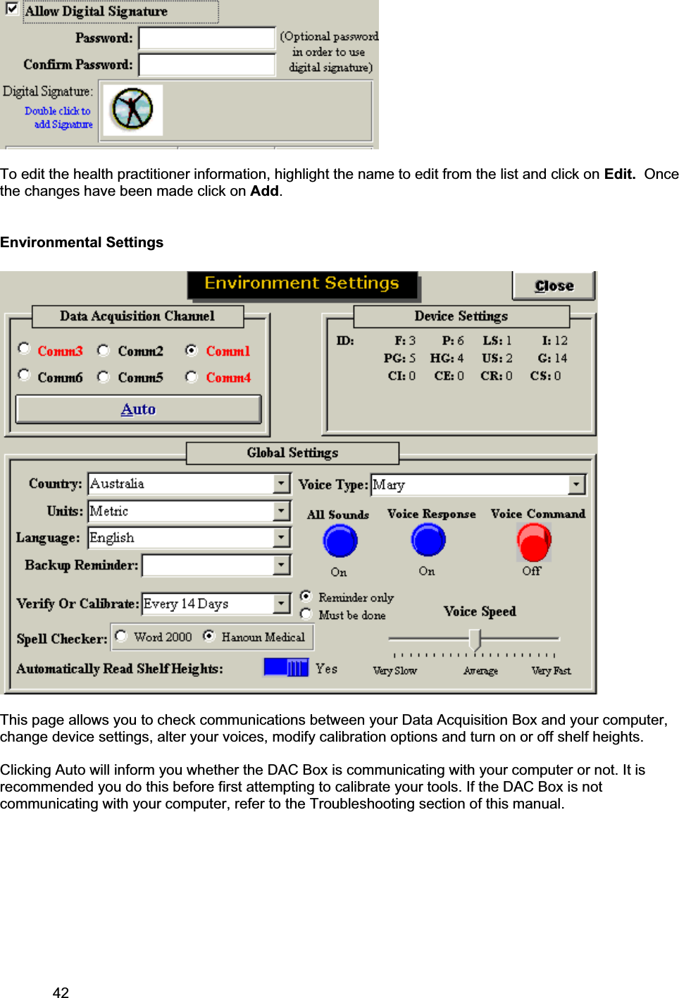
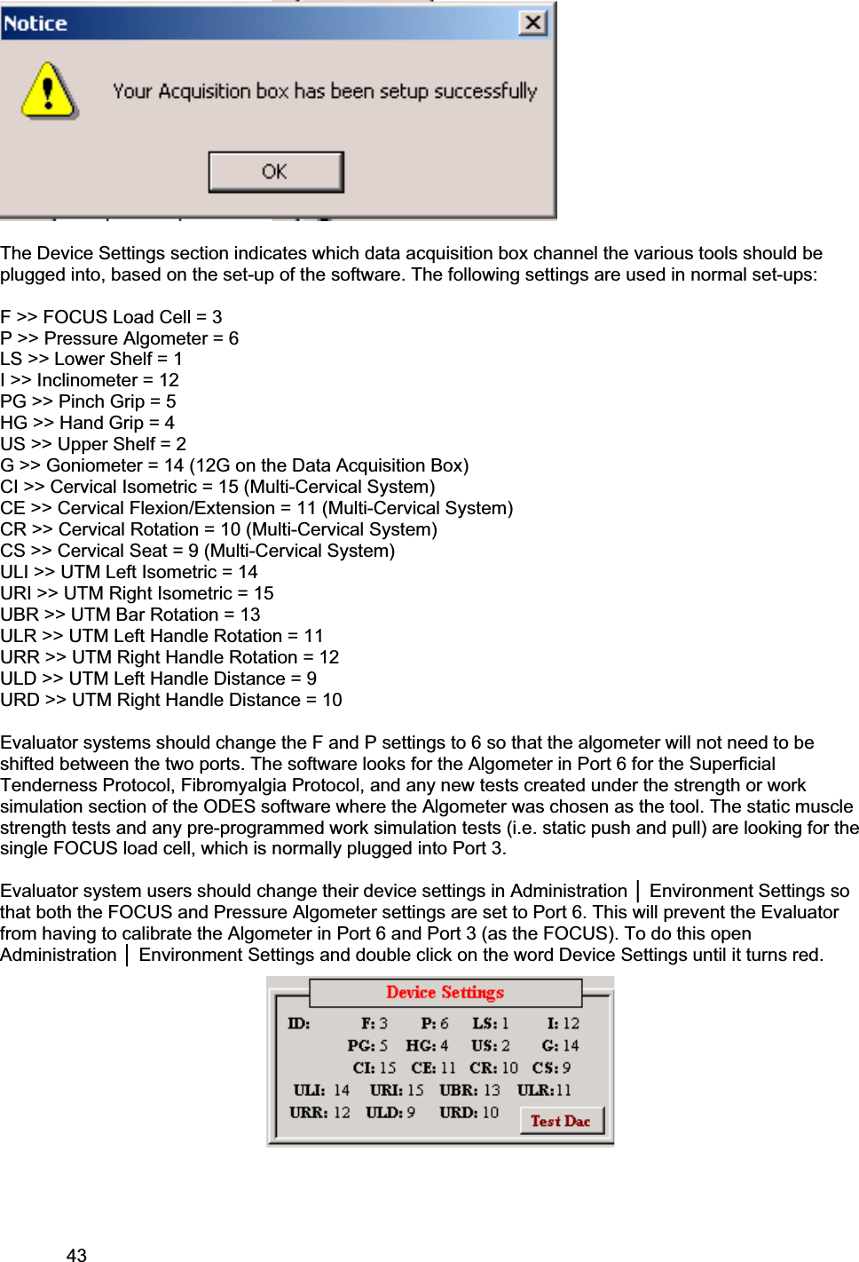
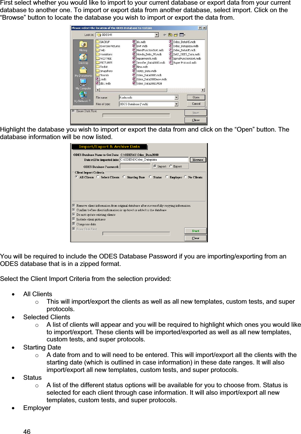
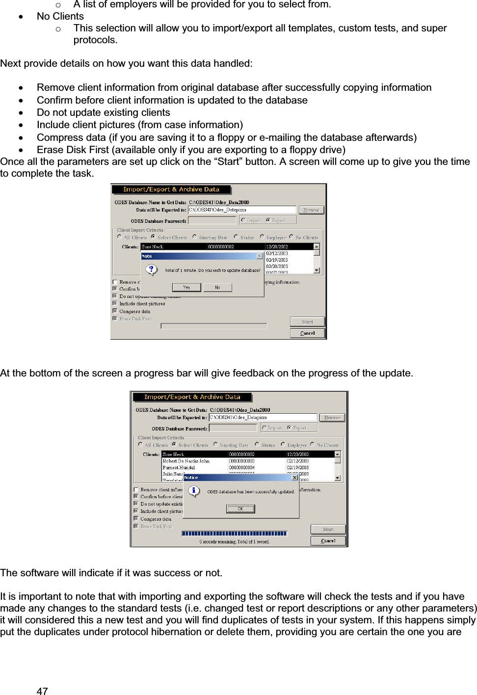
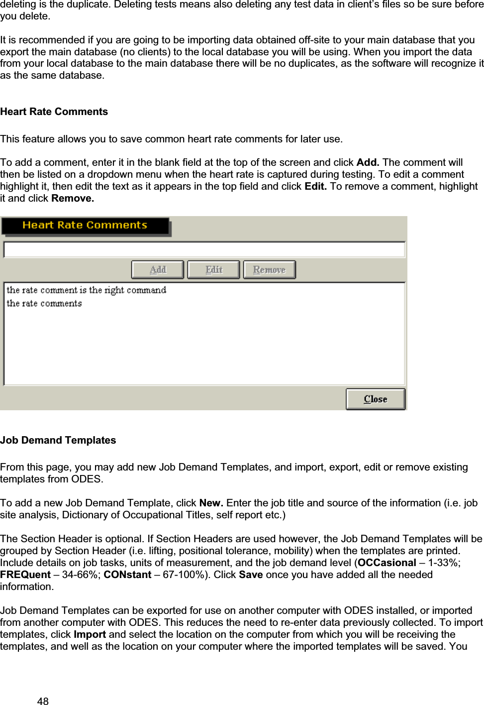
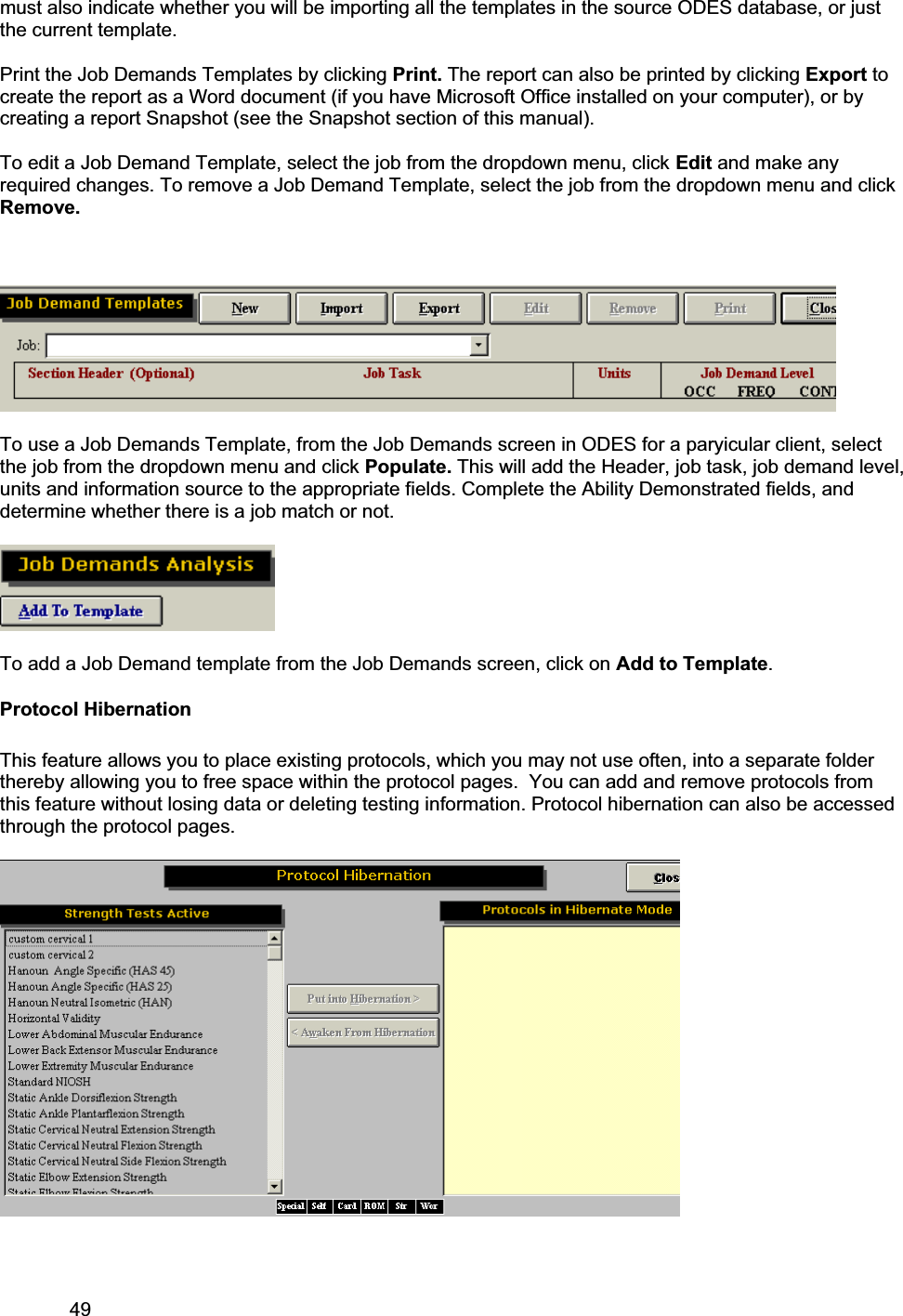
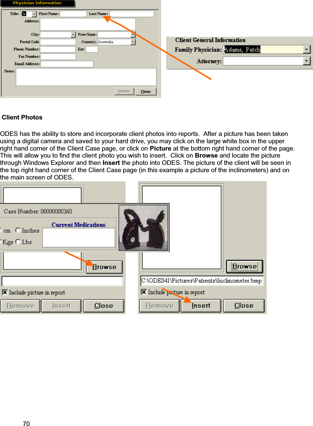
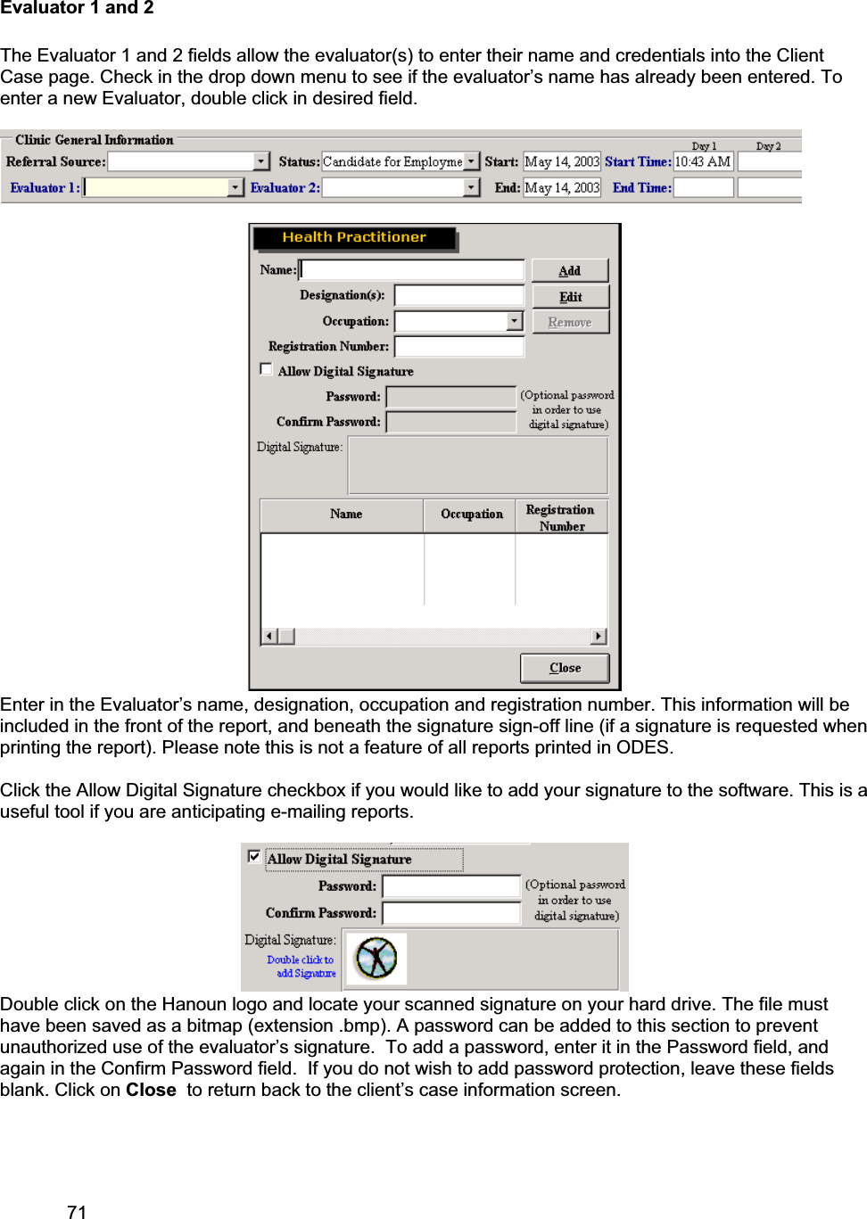
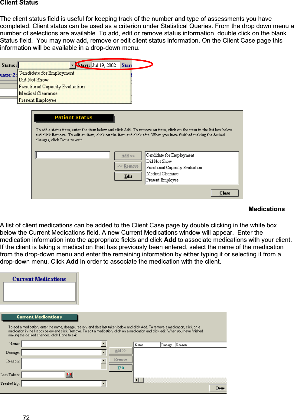
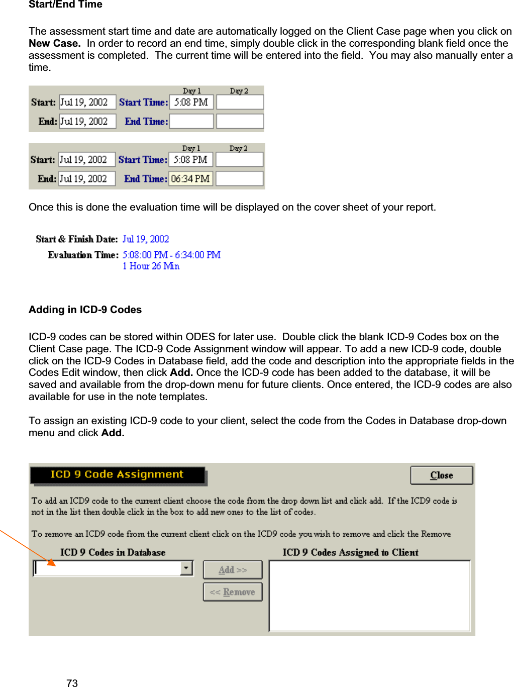
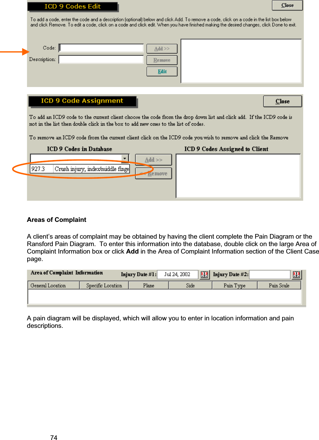
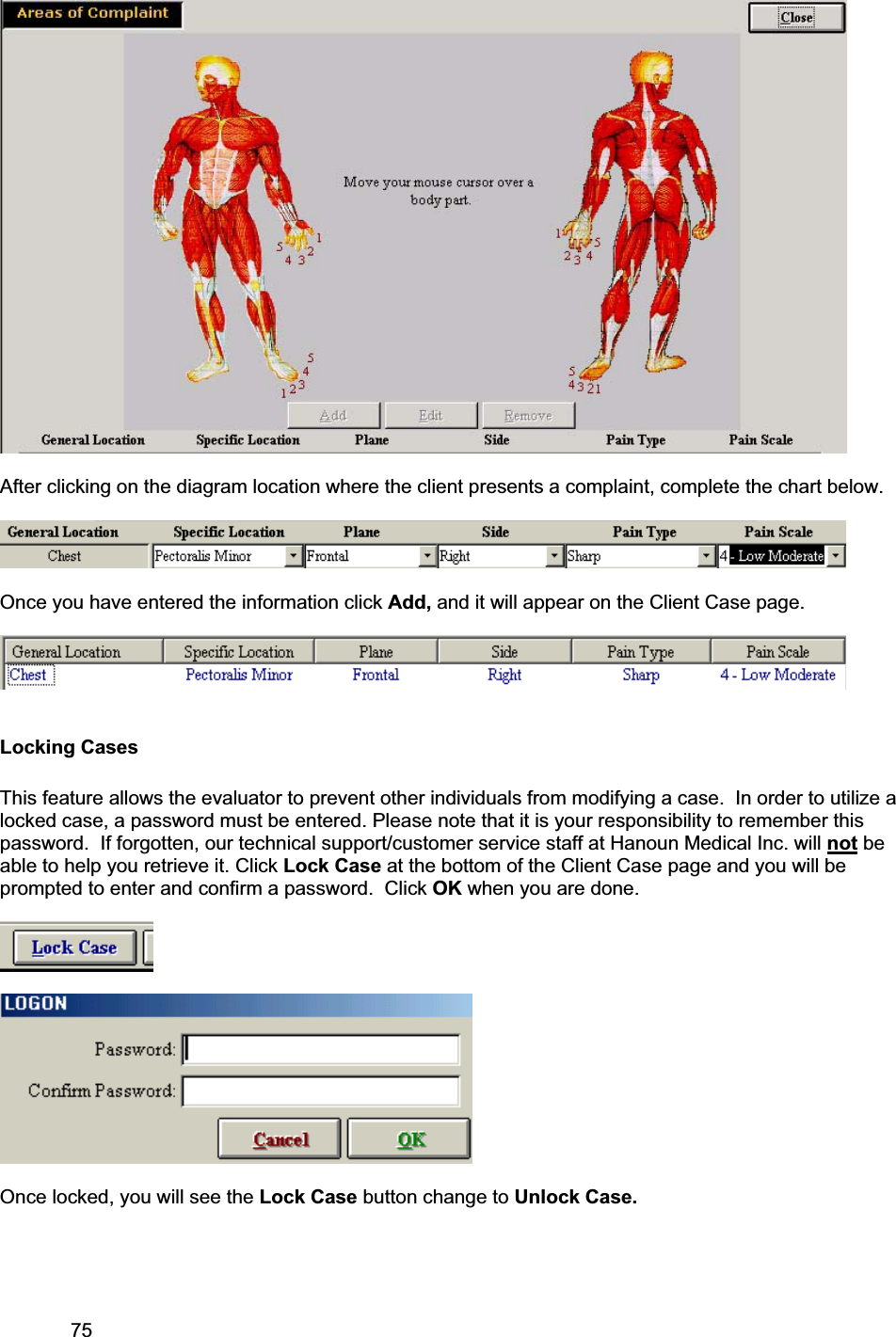
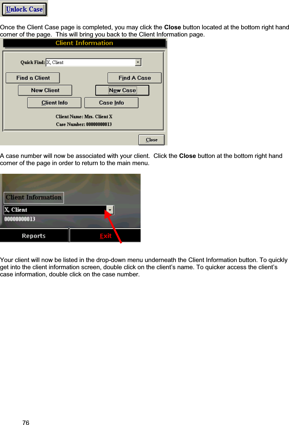
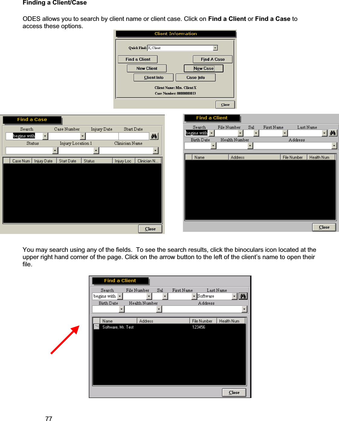
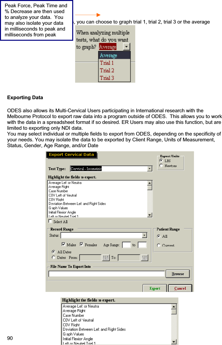
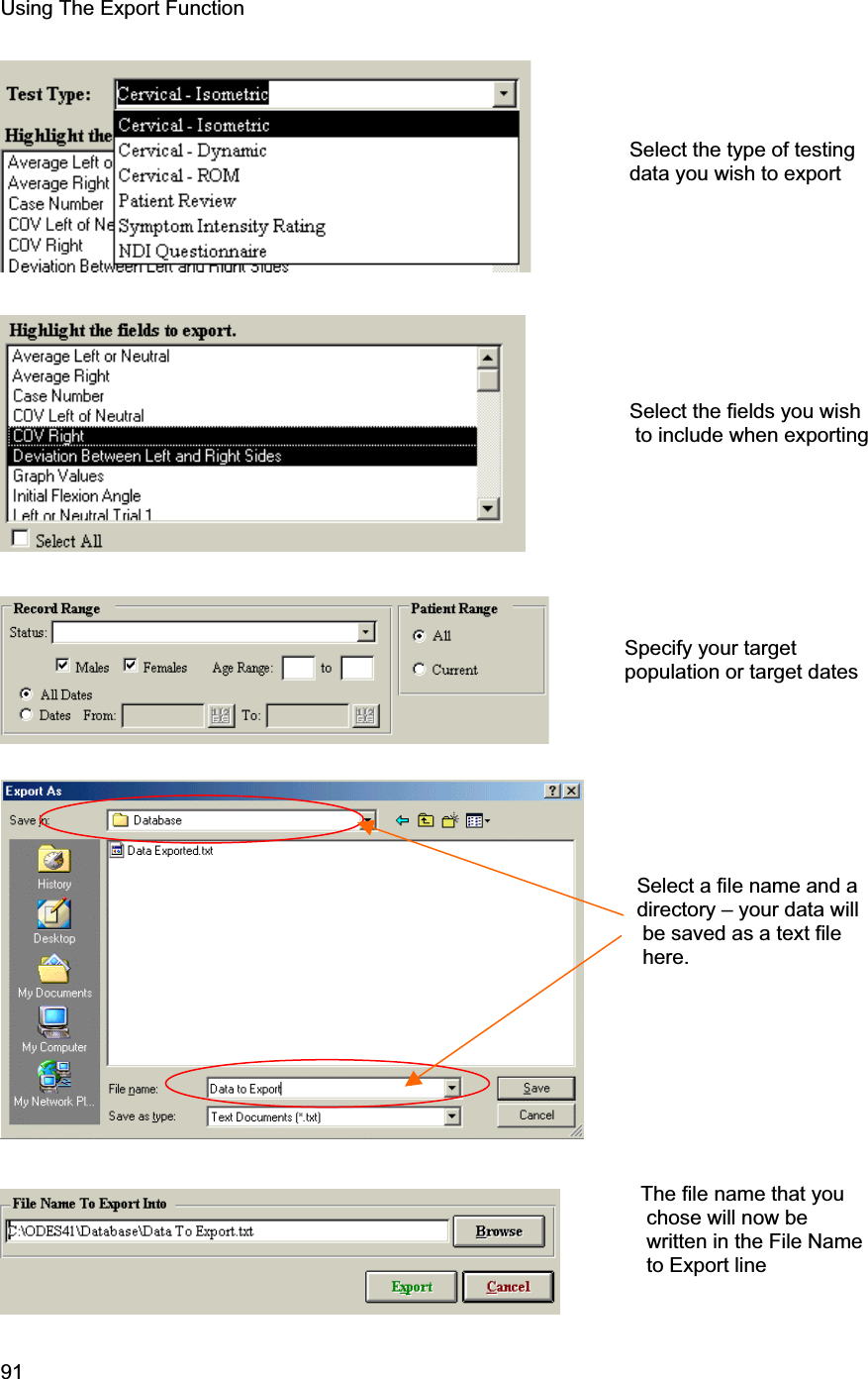
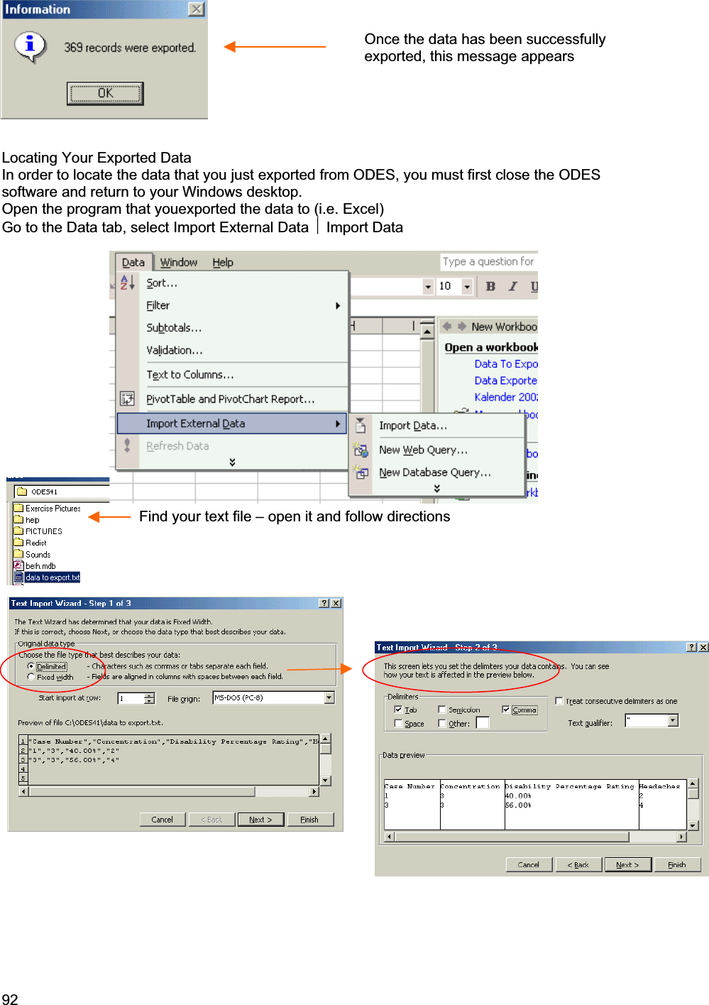
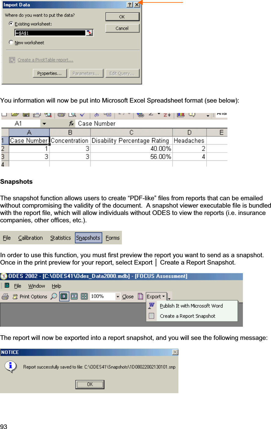

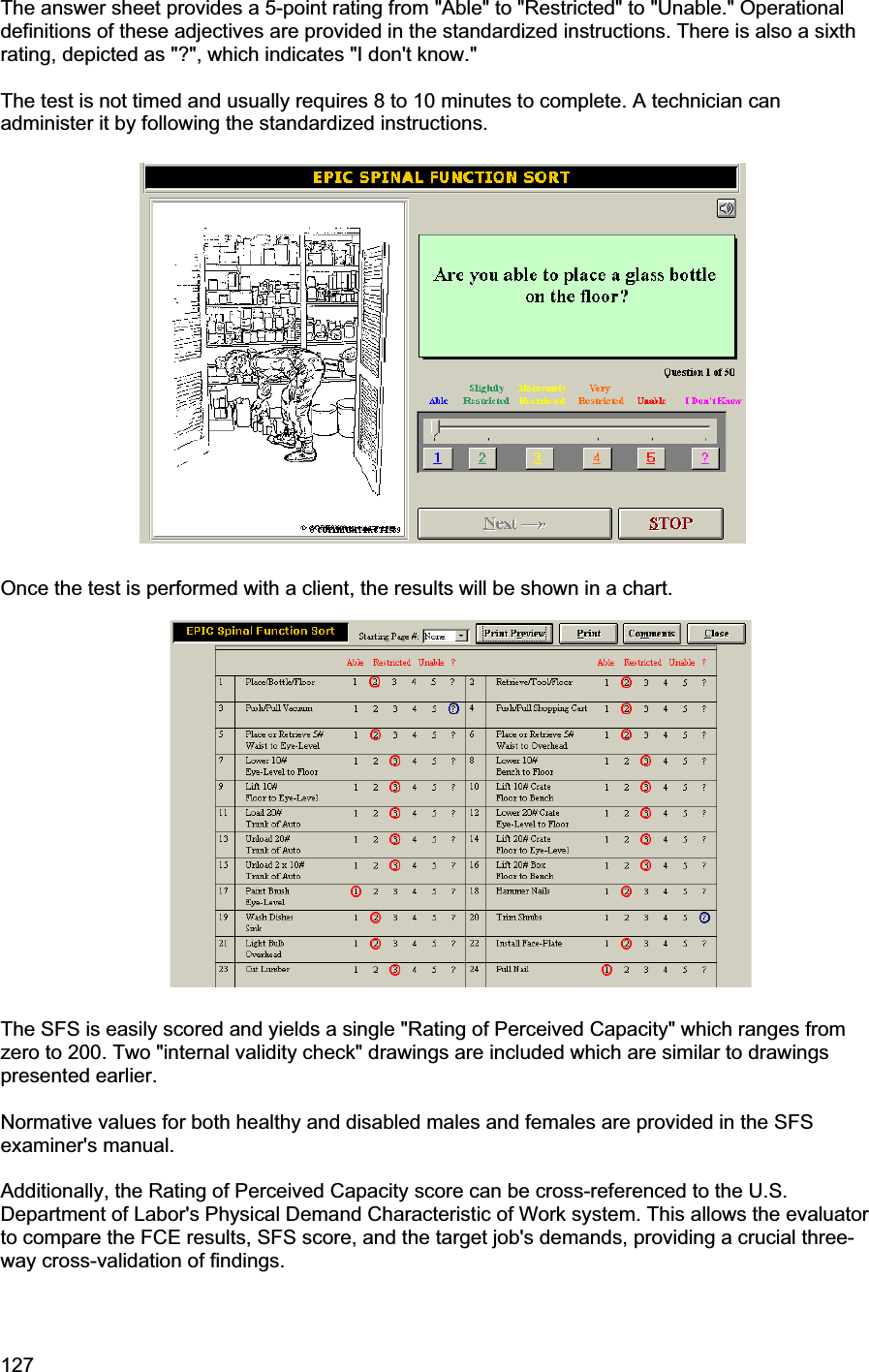
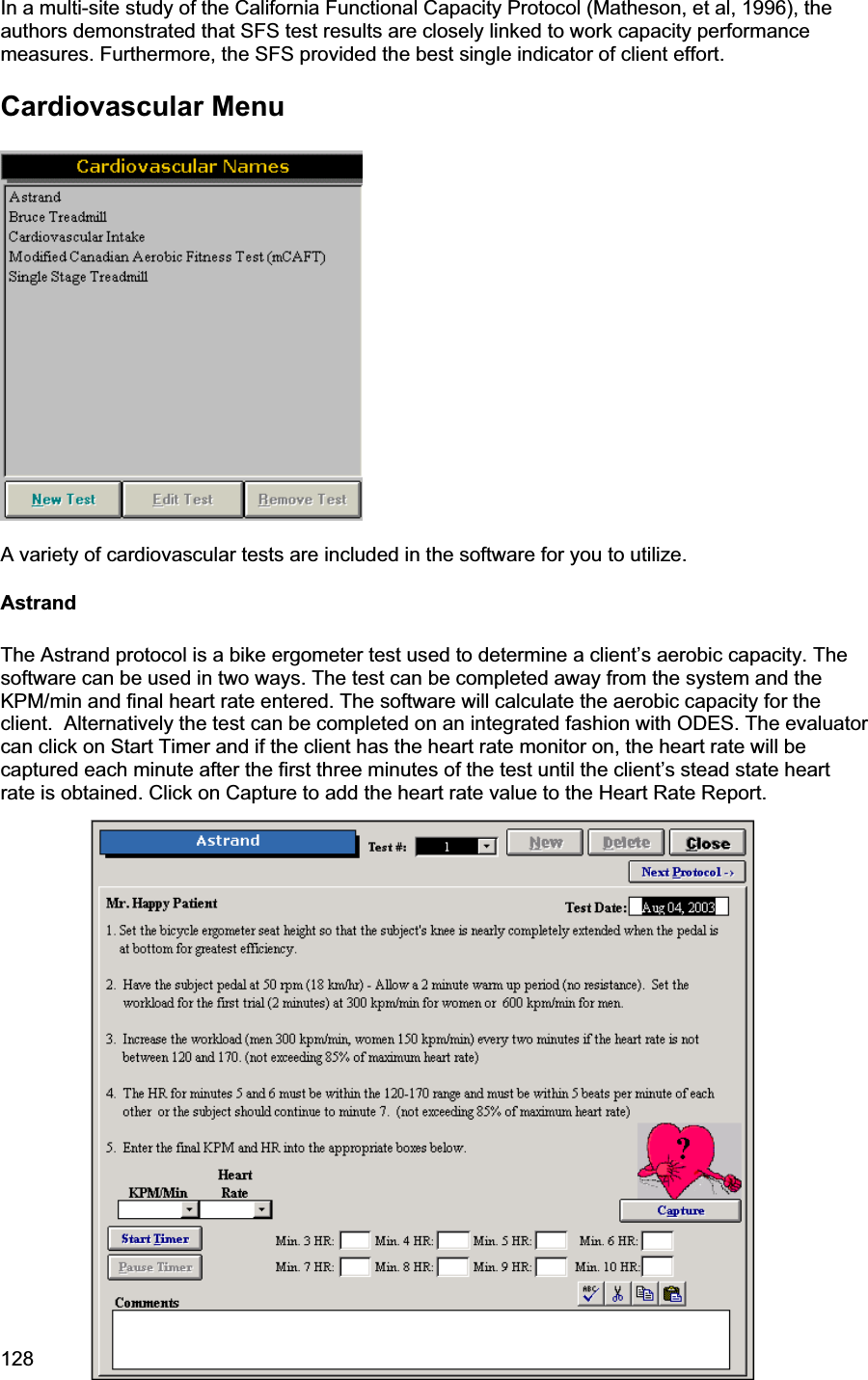
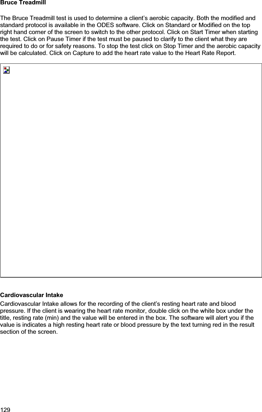
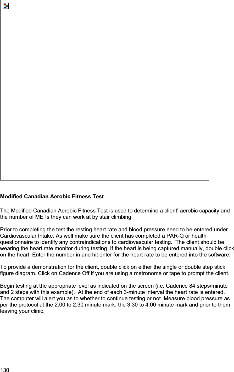
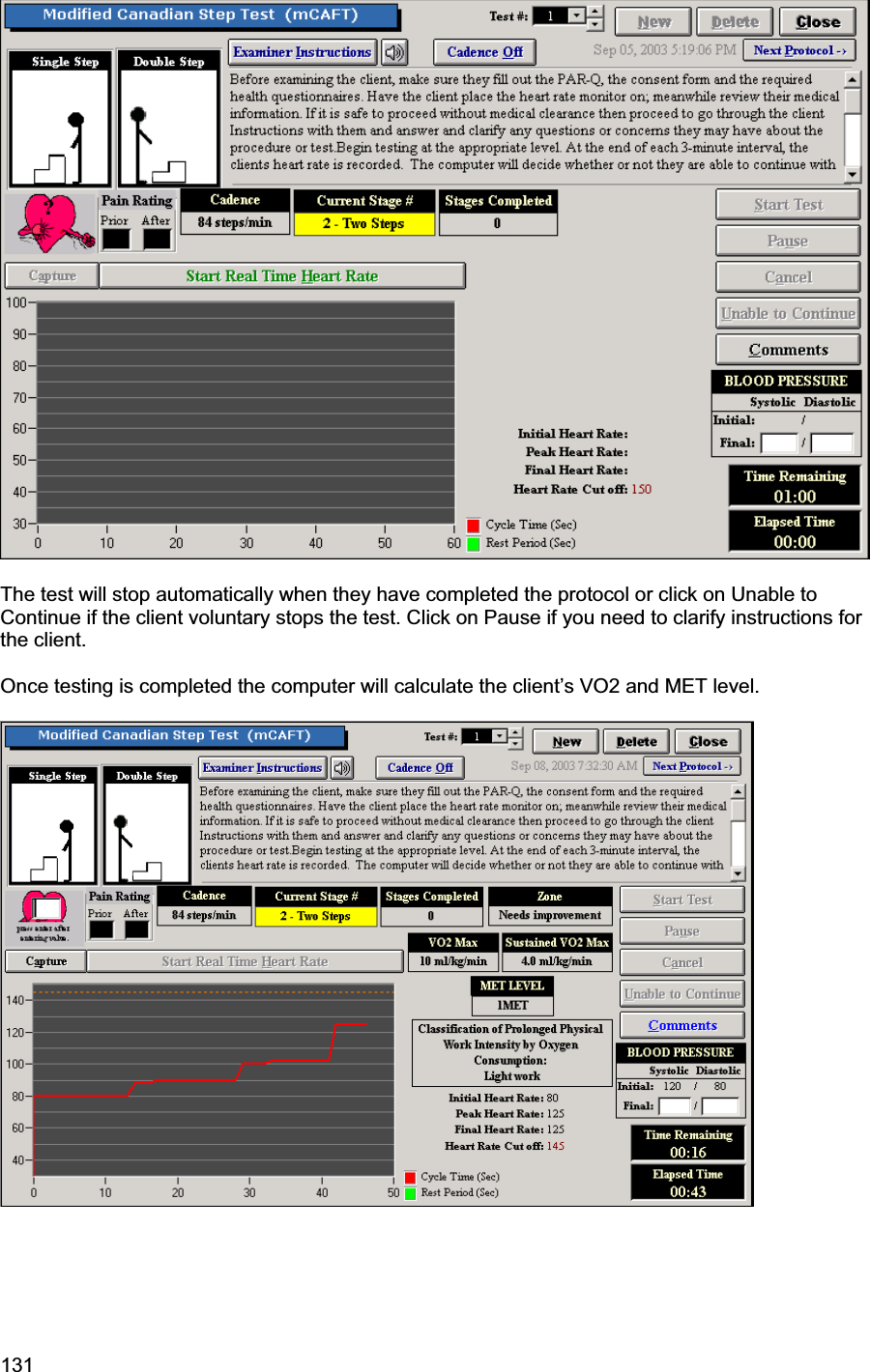
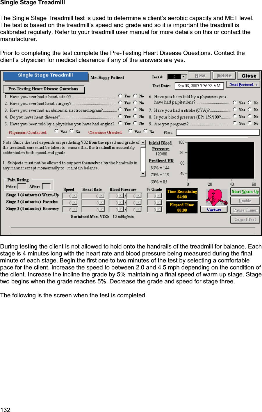
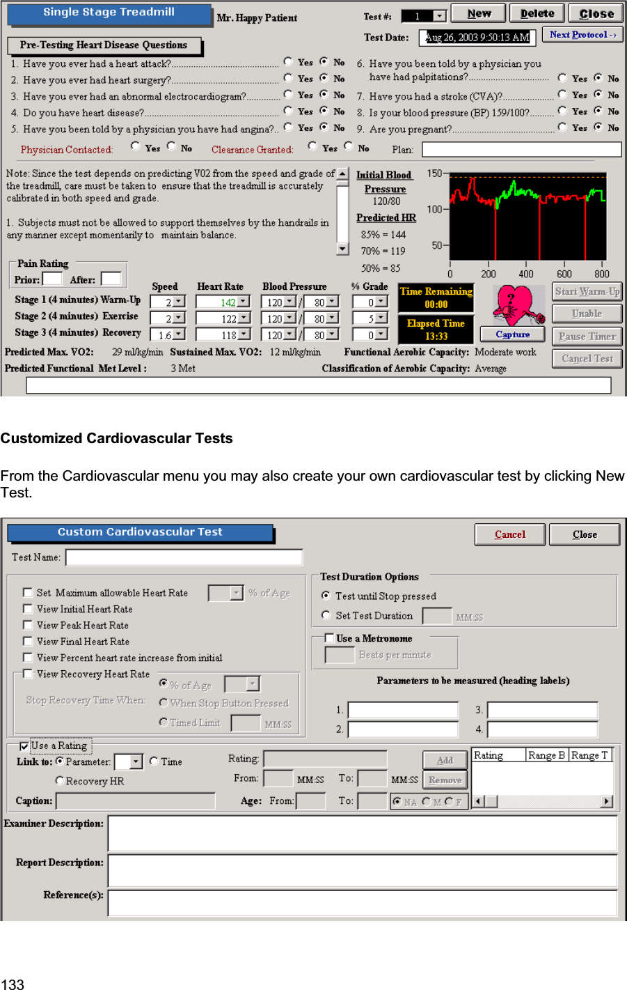
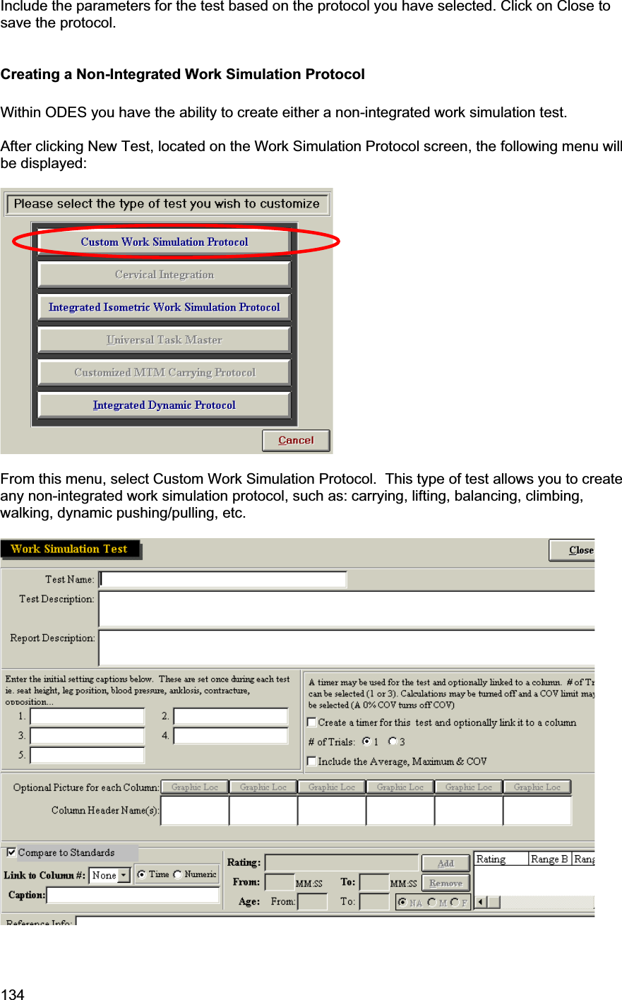
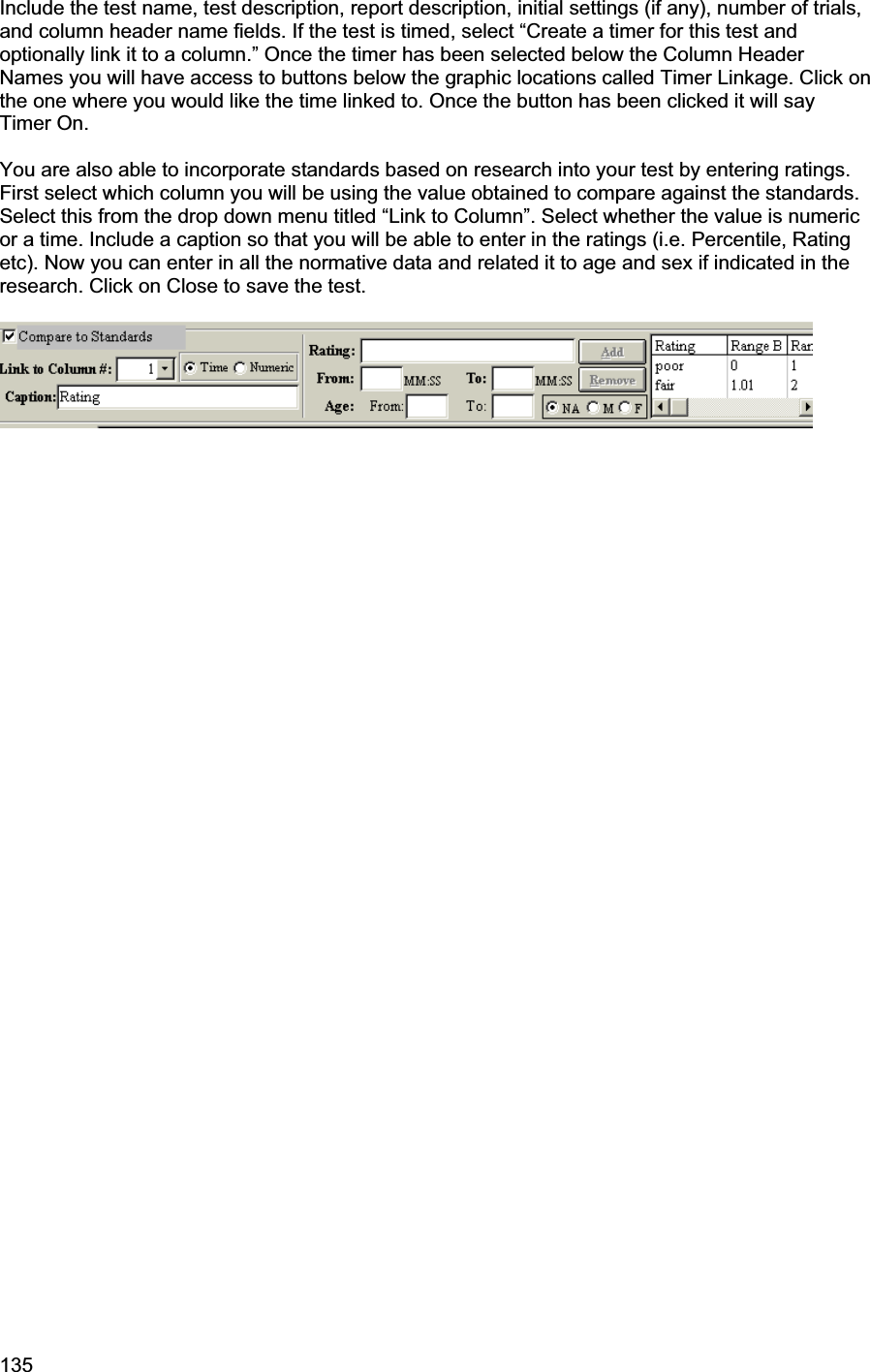
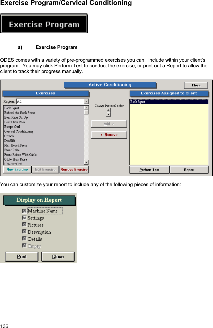
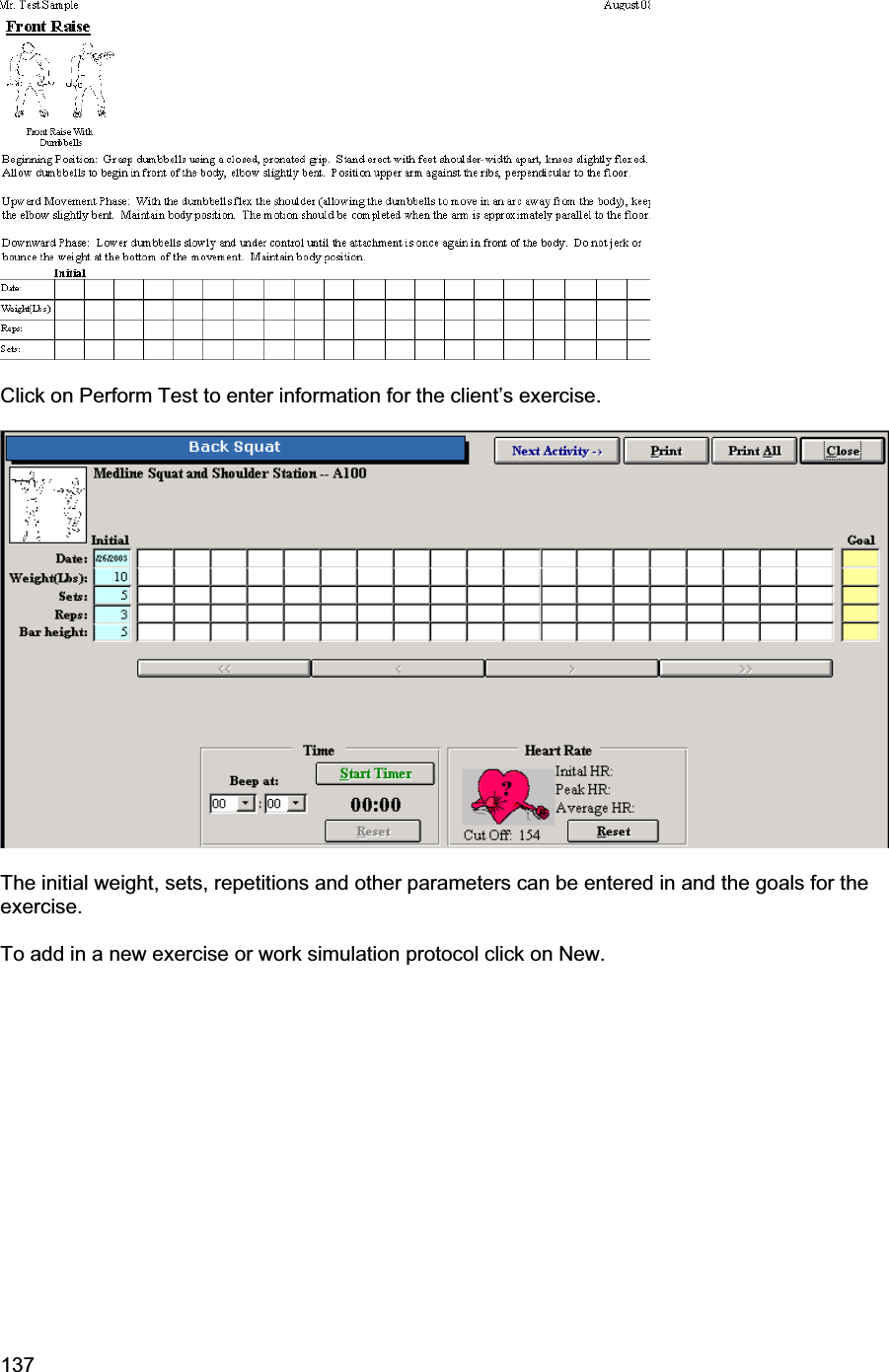
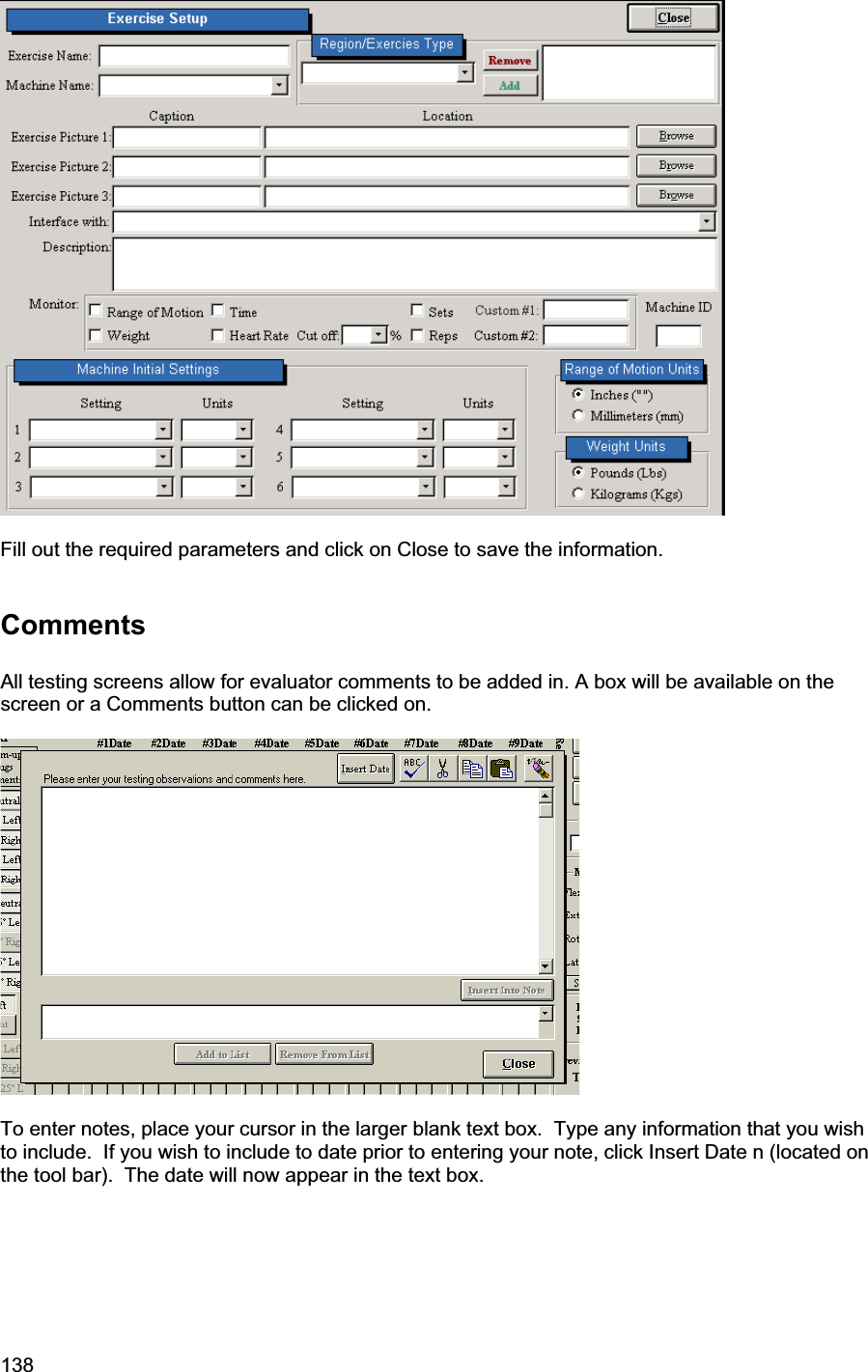
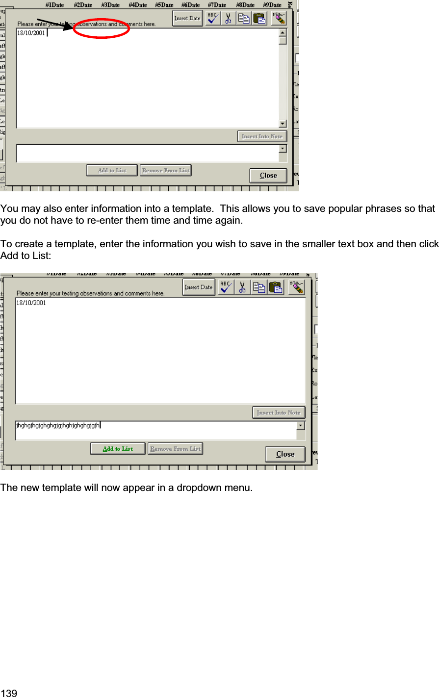
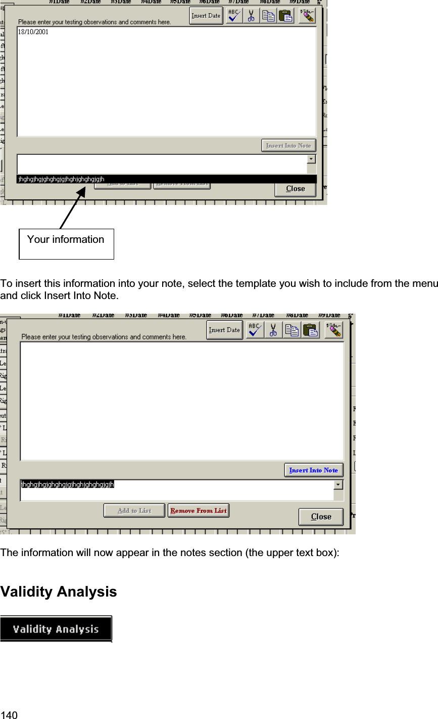
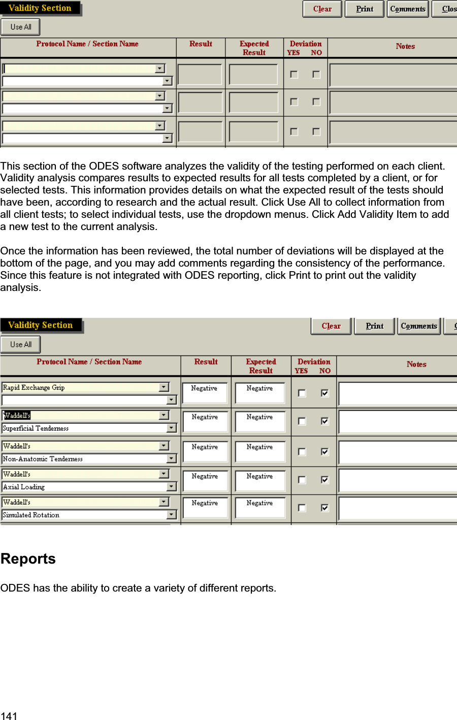
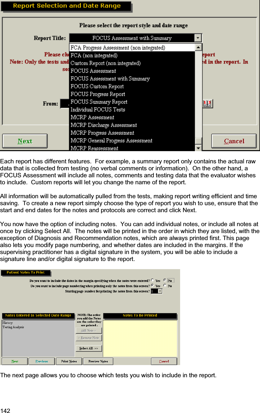
![118 Begin by writing what you wish to include in the report, but use the merge fields in order to automatically query data. To use the merge fields, select the field from the Insert Field dropdown menu and click Insert. This will place the merge field in the template at the spot where your cursor was located. The merge field will have square brackets around it. You may create your own merge field by typing the possible options and placing square brackets around each one. This is useful in situations where there are a limited number of options (i.e. “arrived [on time][late] for the assessment…”). Once finished, click Close, then click Cancel Edit on the Template page. Select your template and paste it into place You may now use the “tab” key on your keyboard to find and replace any outstanding fields on the template. Remember that you will need to choose the appropriate comments in certain](https://usermanual.wiki/BTE-Technologies/DAQRETROFIT.Users-Manual-1/User-Guide-631851-Page-118.png)