BTE Technologies DAQRETROFIT Strength measurement equipment. User Manual 40050053 rev A
BTE Technologies, Inc. Strength measurement equipment. 40050053 rev A
UserManual.wiki
>
BTE Technologies
>
DAQRETROFIT User Manual
>
Users Manual 2
Contents
1.
FCC Manual Addendum
2.
Users Manual 1
3.
Users Manual 2
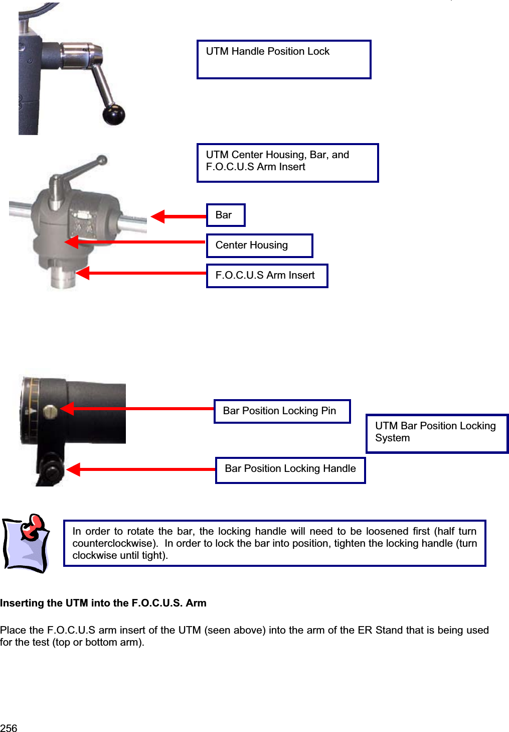
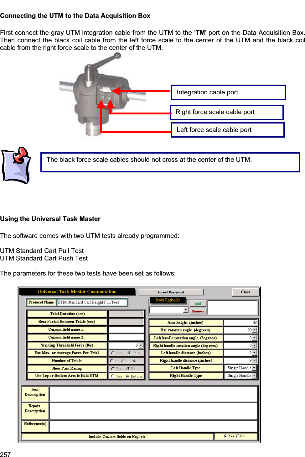
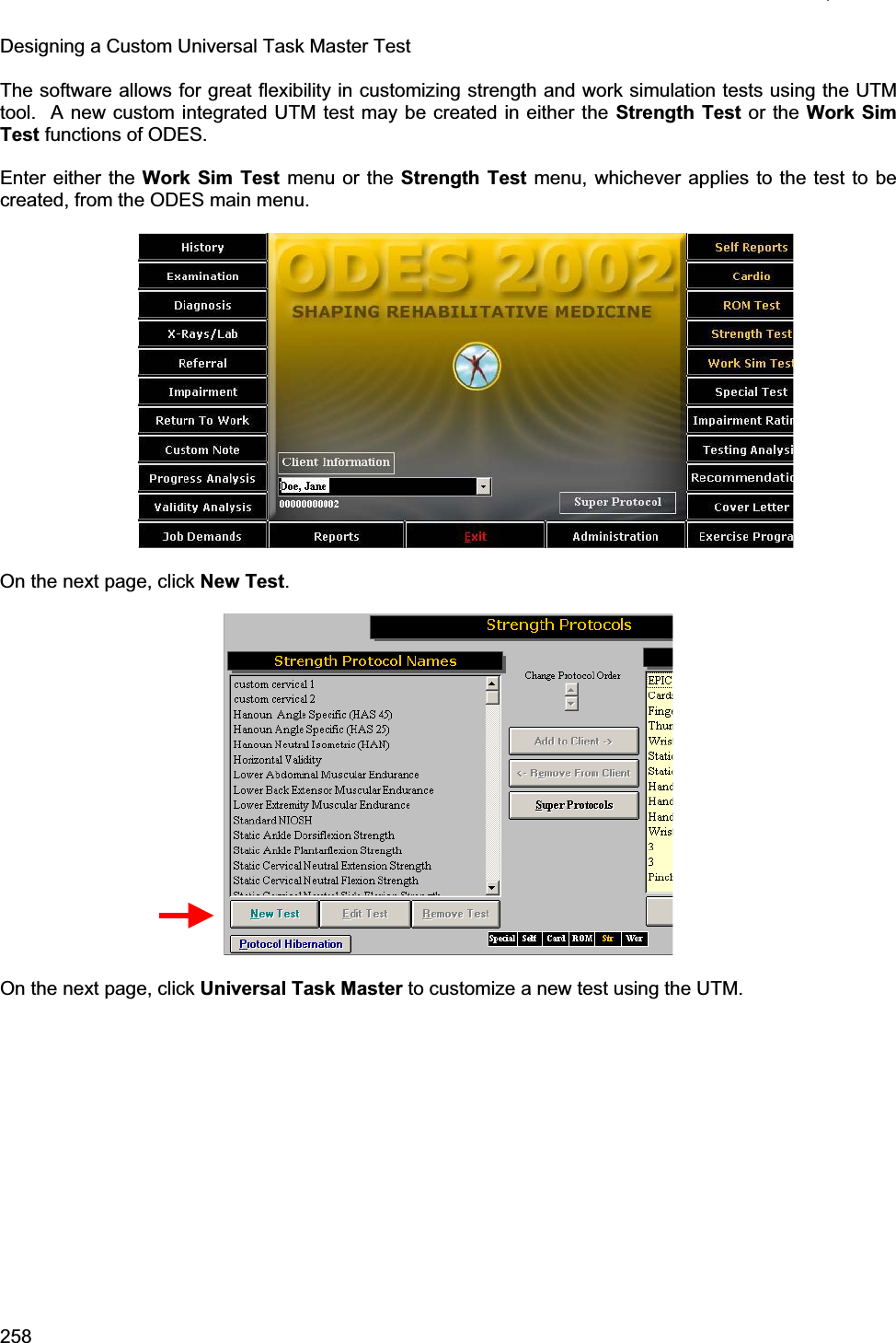
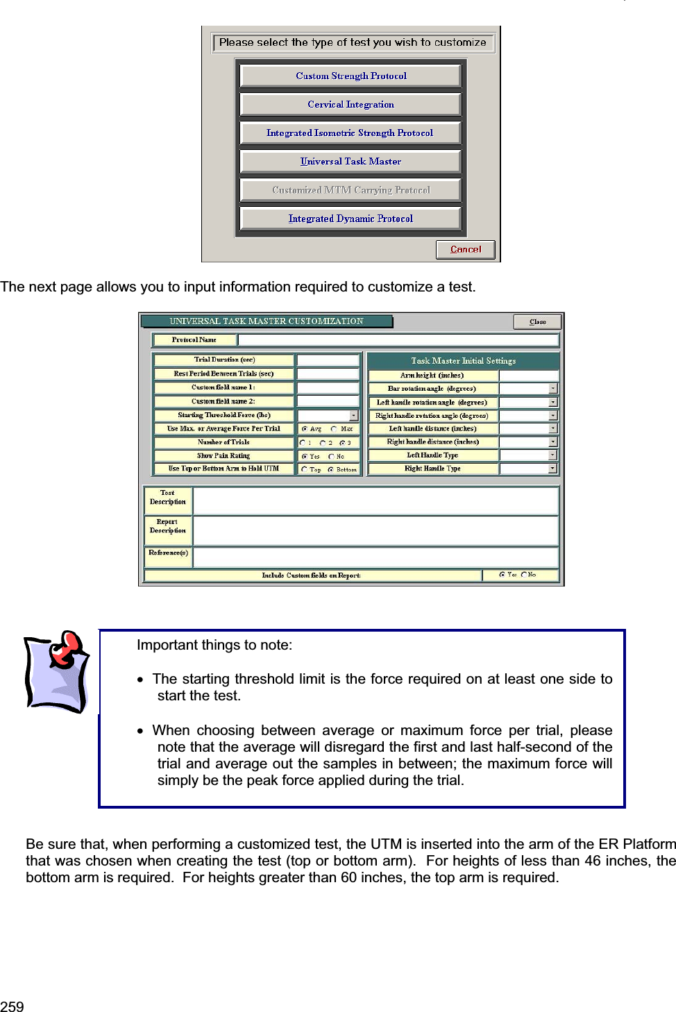
Users Manual 2
Navigation menu
Upload a User Manual
Namespaces
Wiki Guide
HTML
PDF
Info
Views
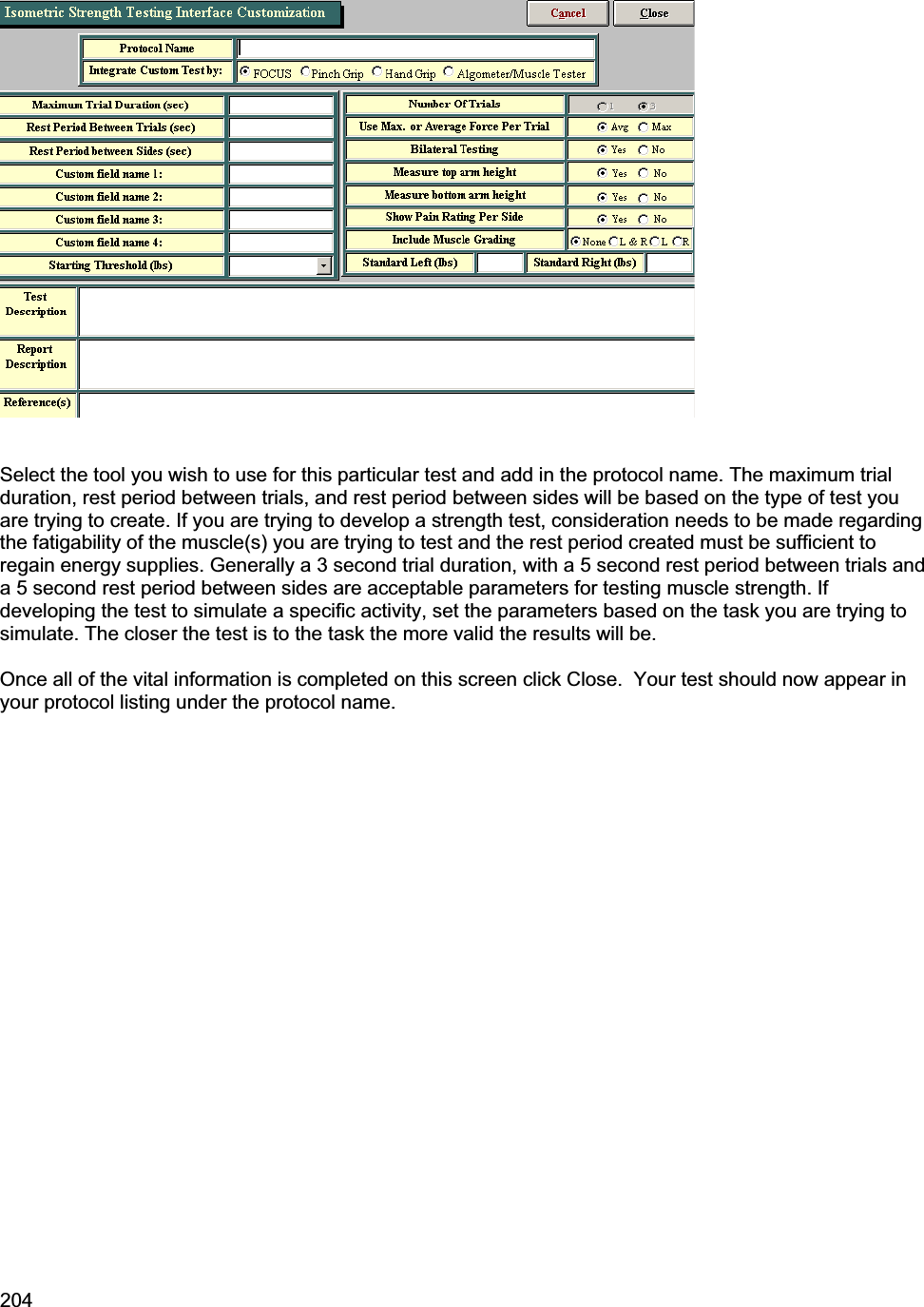
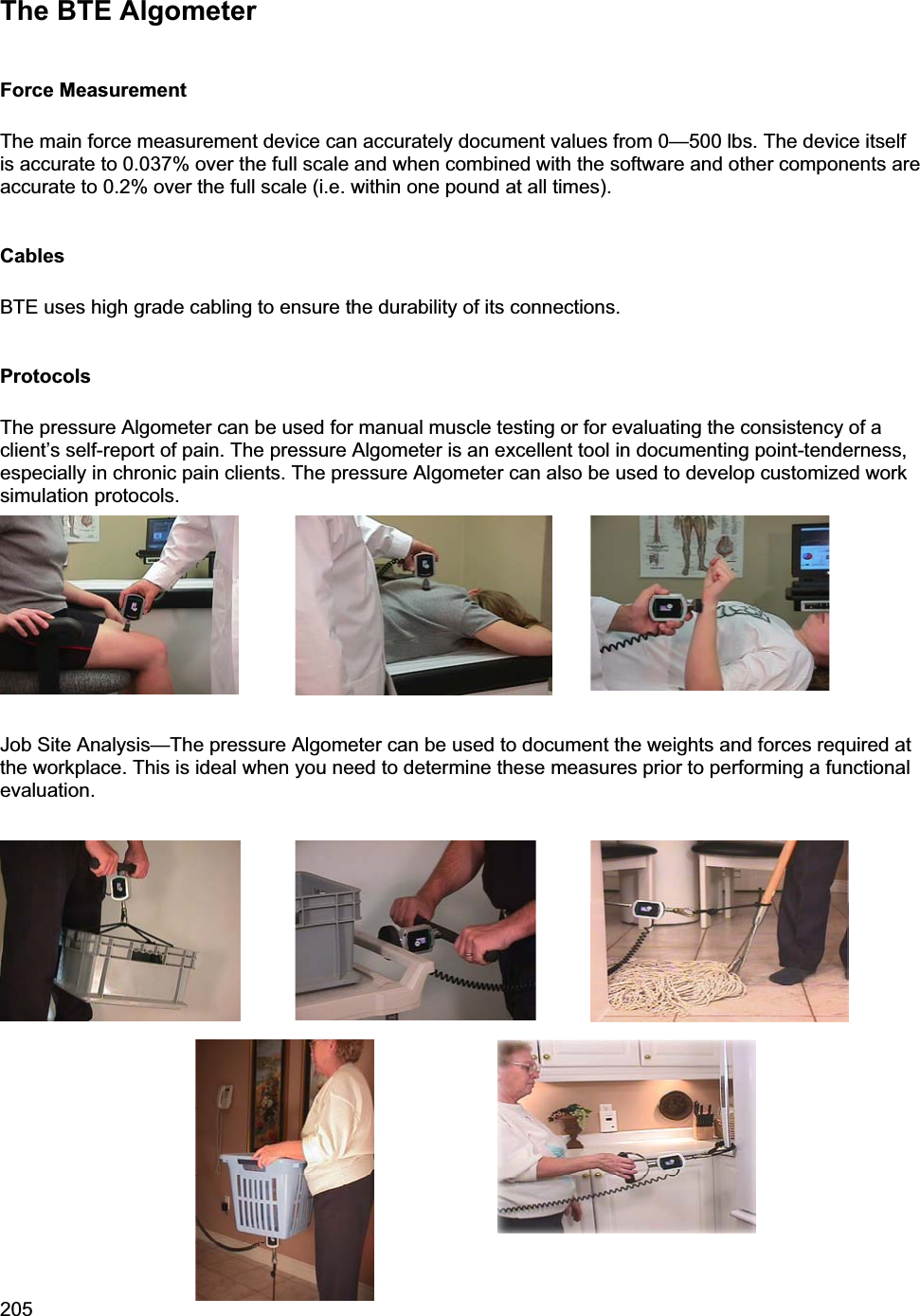
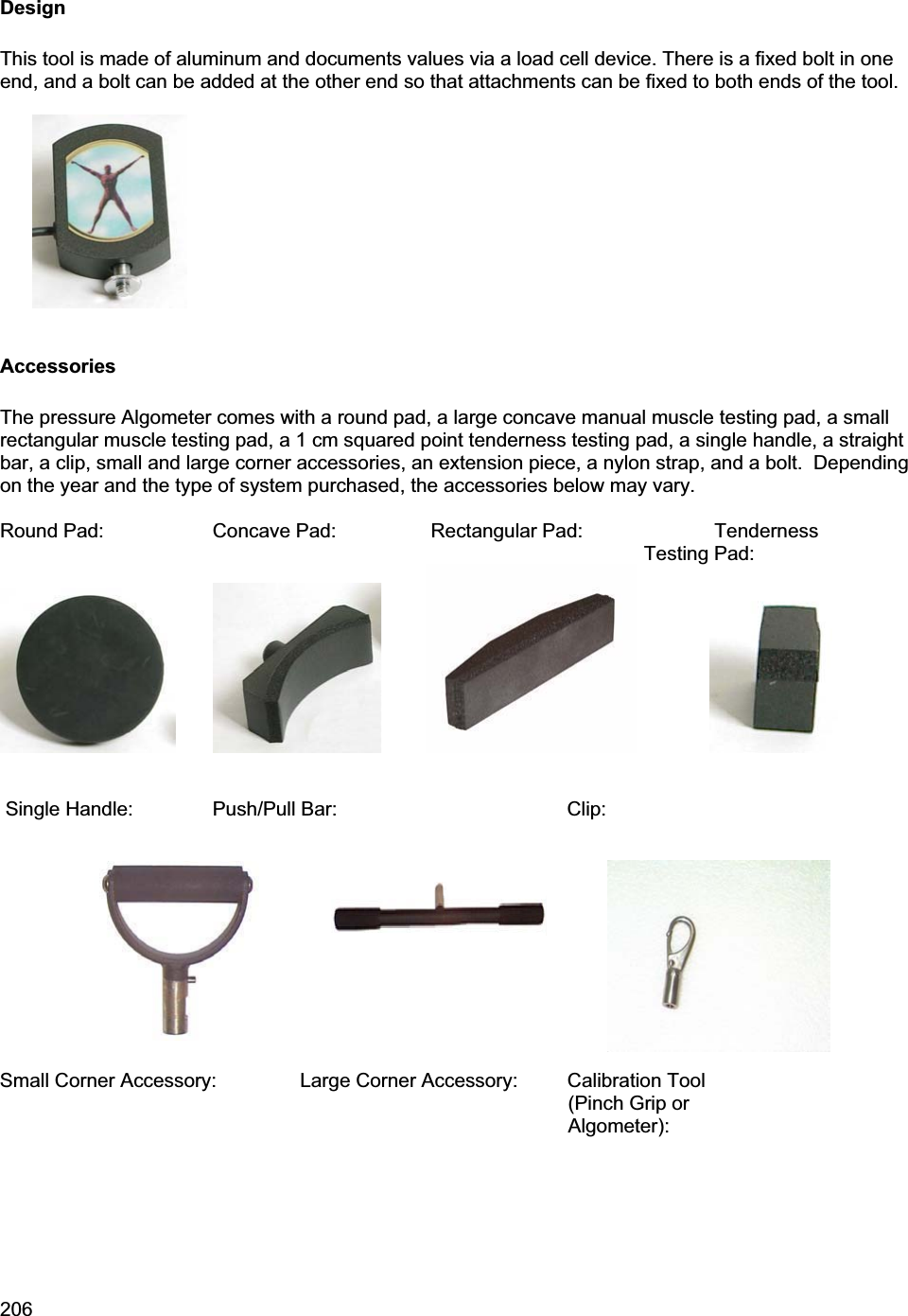
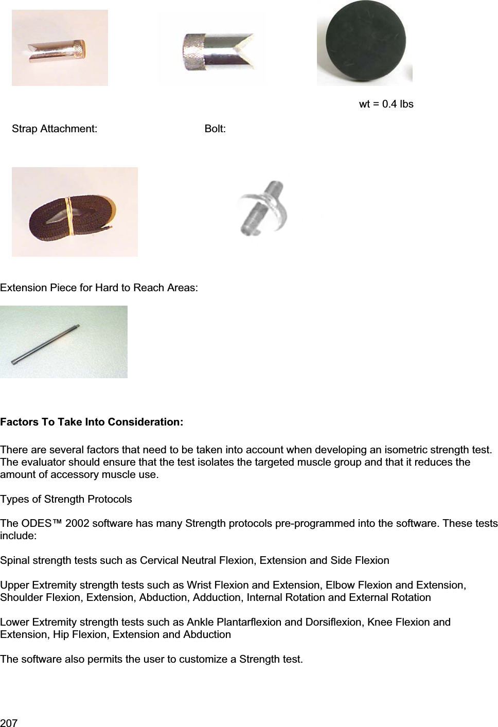
User Manual
Discussion / Help
Navigation