BTI Wireless MBSC08S005RUM mBSC-C RUM User Manual
Bravo Tech (Shenzhen) Co. Ltd. mBSC-C RUM
UserManual.wiki
>
BTI Wireless
>
MBSC08S005RUM User Manual
Users Manual
Navigation menu
Upload a User Manual
Namespaces
Wiki Guide
HTML
PDF
Info
Views
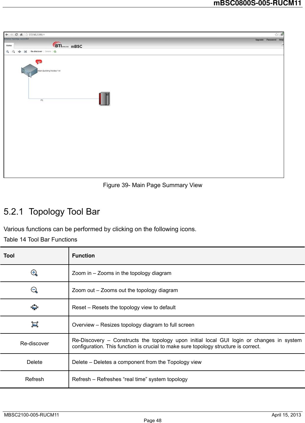
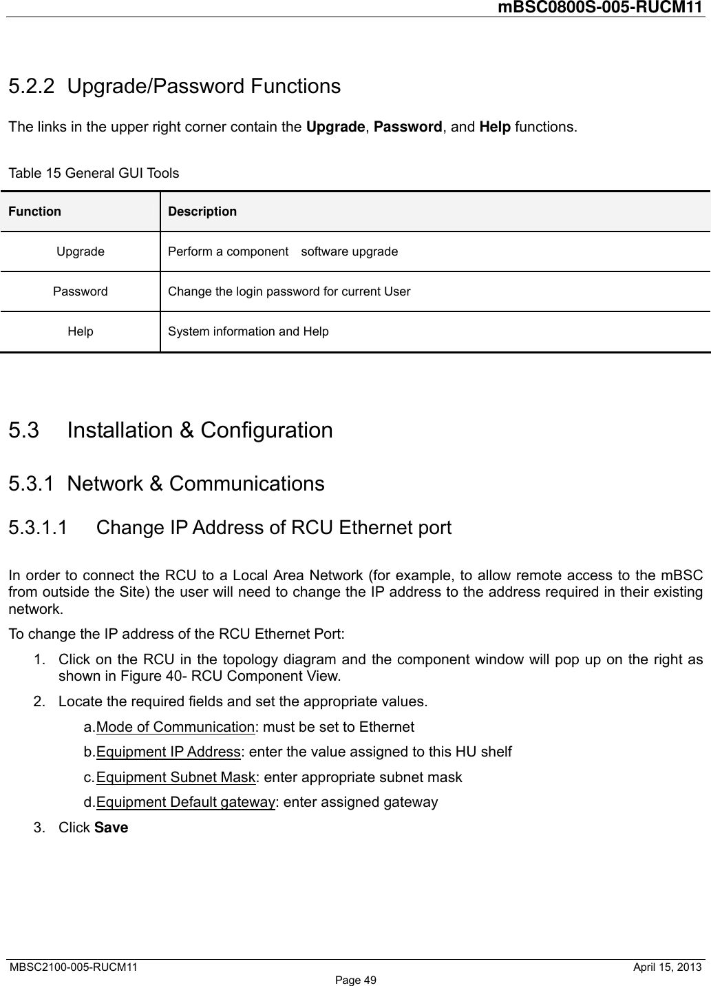
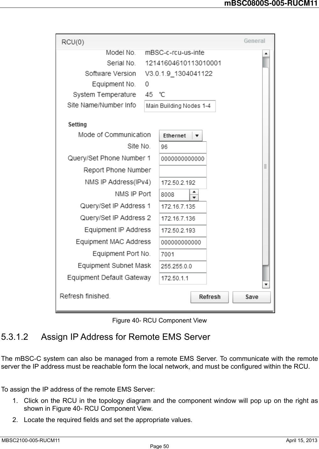
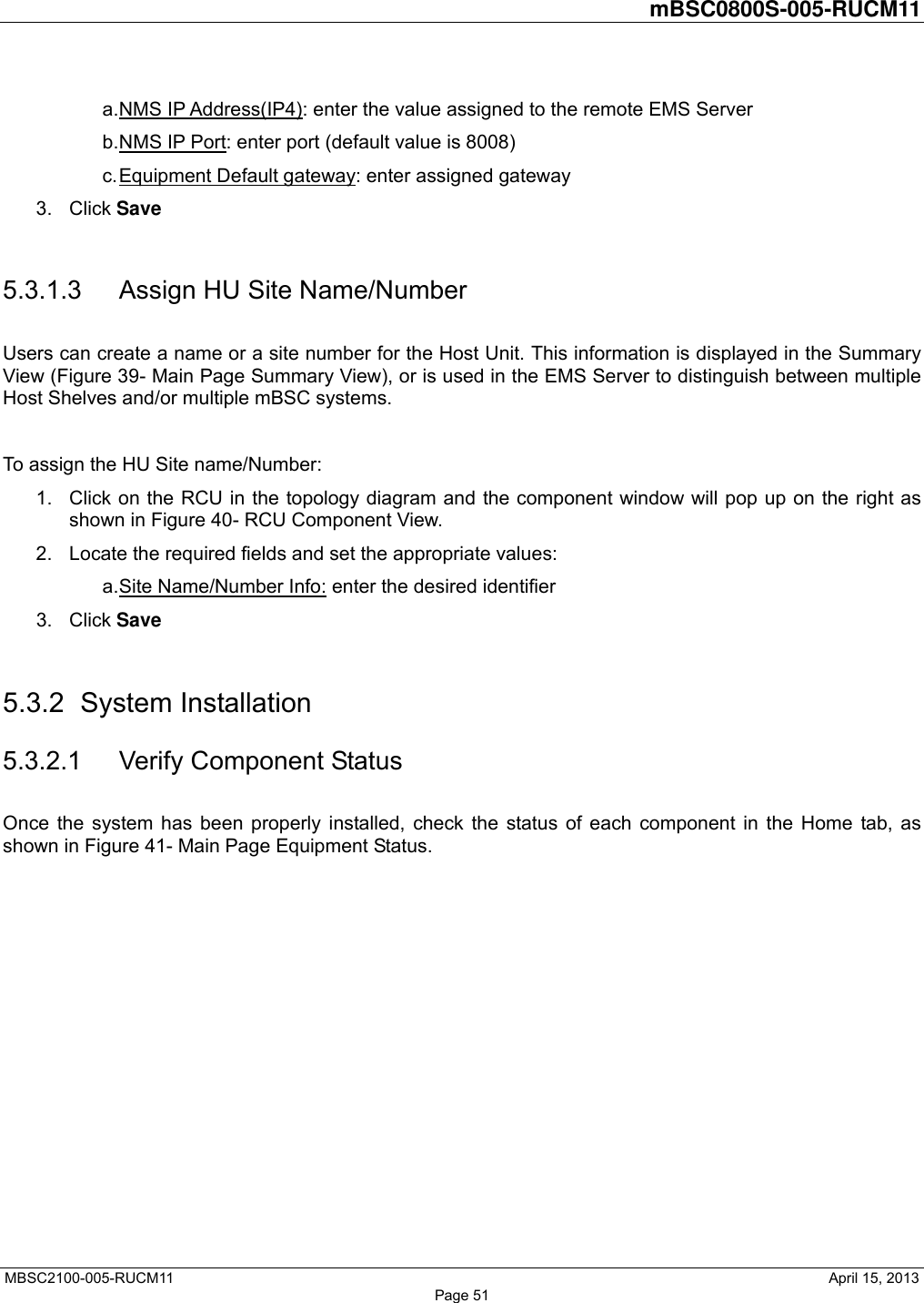
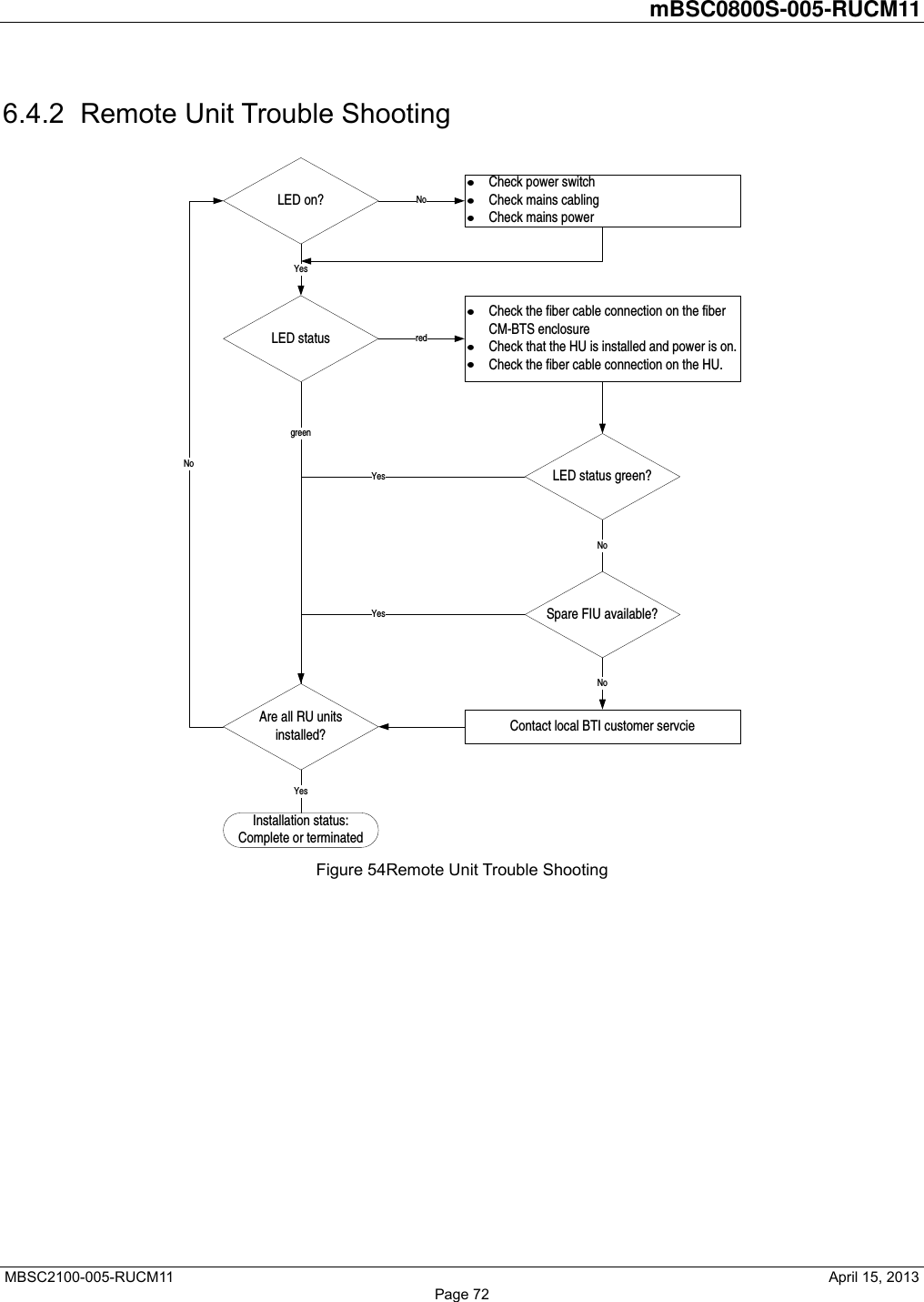
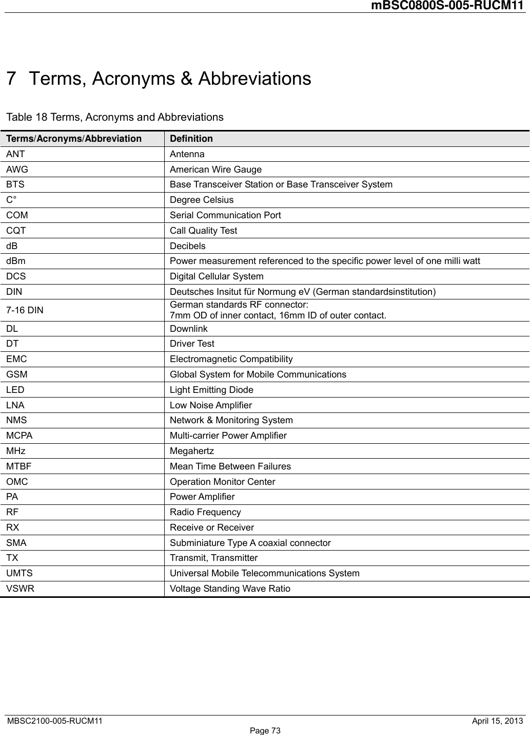
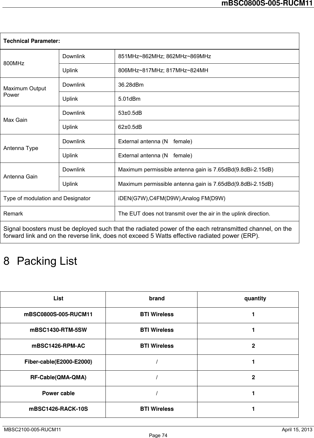
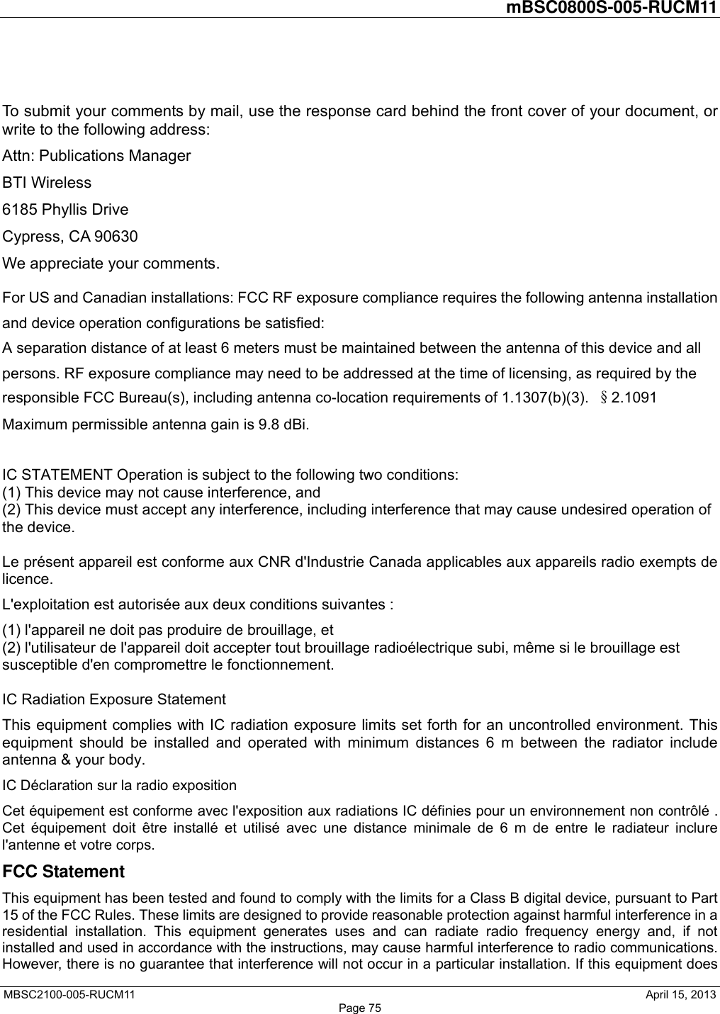
User Manual
Discussion / Help
Navigation