Balluff UHF-CNTL-02 UHF RFID Controller User Manual Version 28 05 09
BALLUFF inc UHF RFID Controller Version 28 05 09
UserManual.wiki
>
Balluff
>
UHF CNTL 02 User Manual
User Manual
Navigation menu
Upload a User Manual
Namespaces
Wiki Guide
HTML
PDF
Info
Views
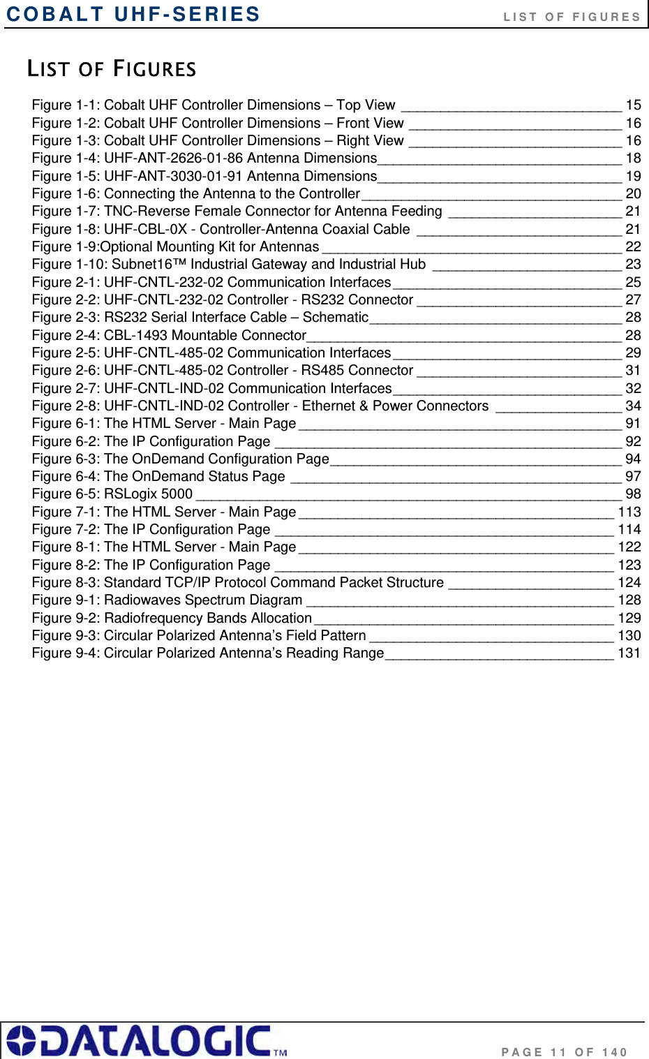
User Manual
Discussion / Help
Navigation
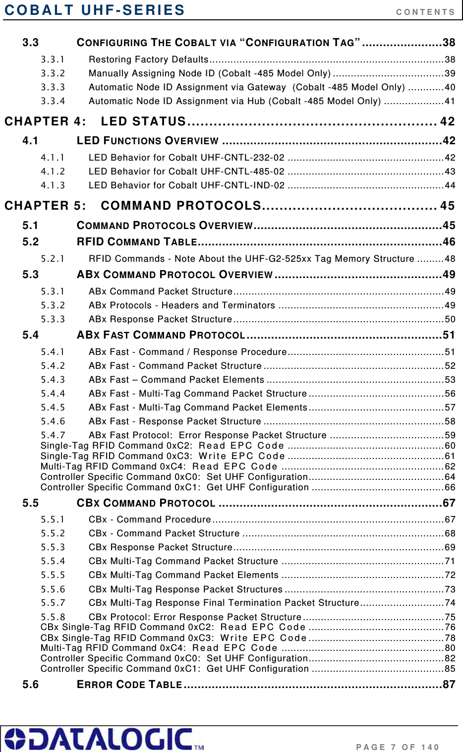

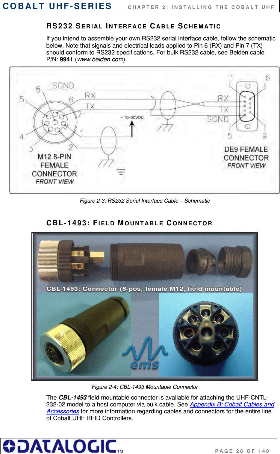
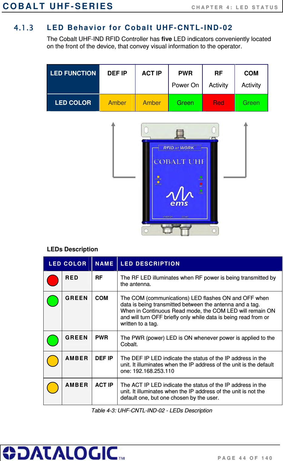
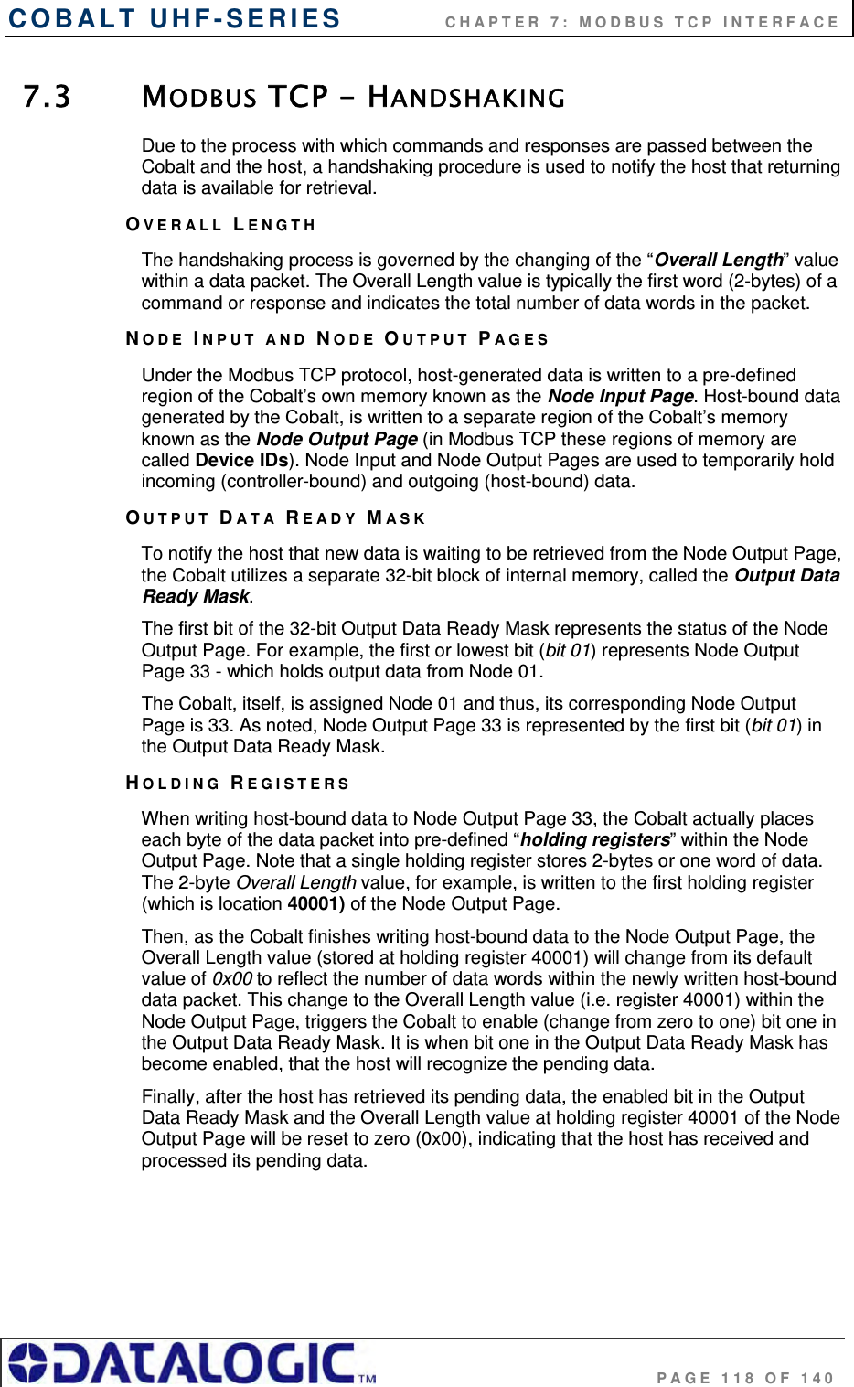
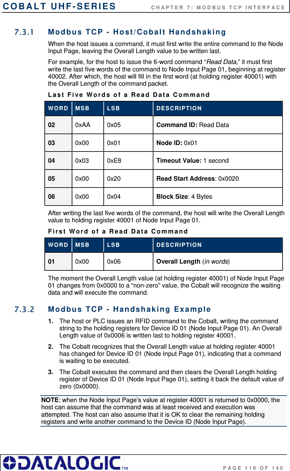
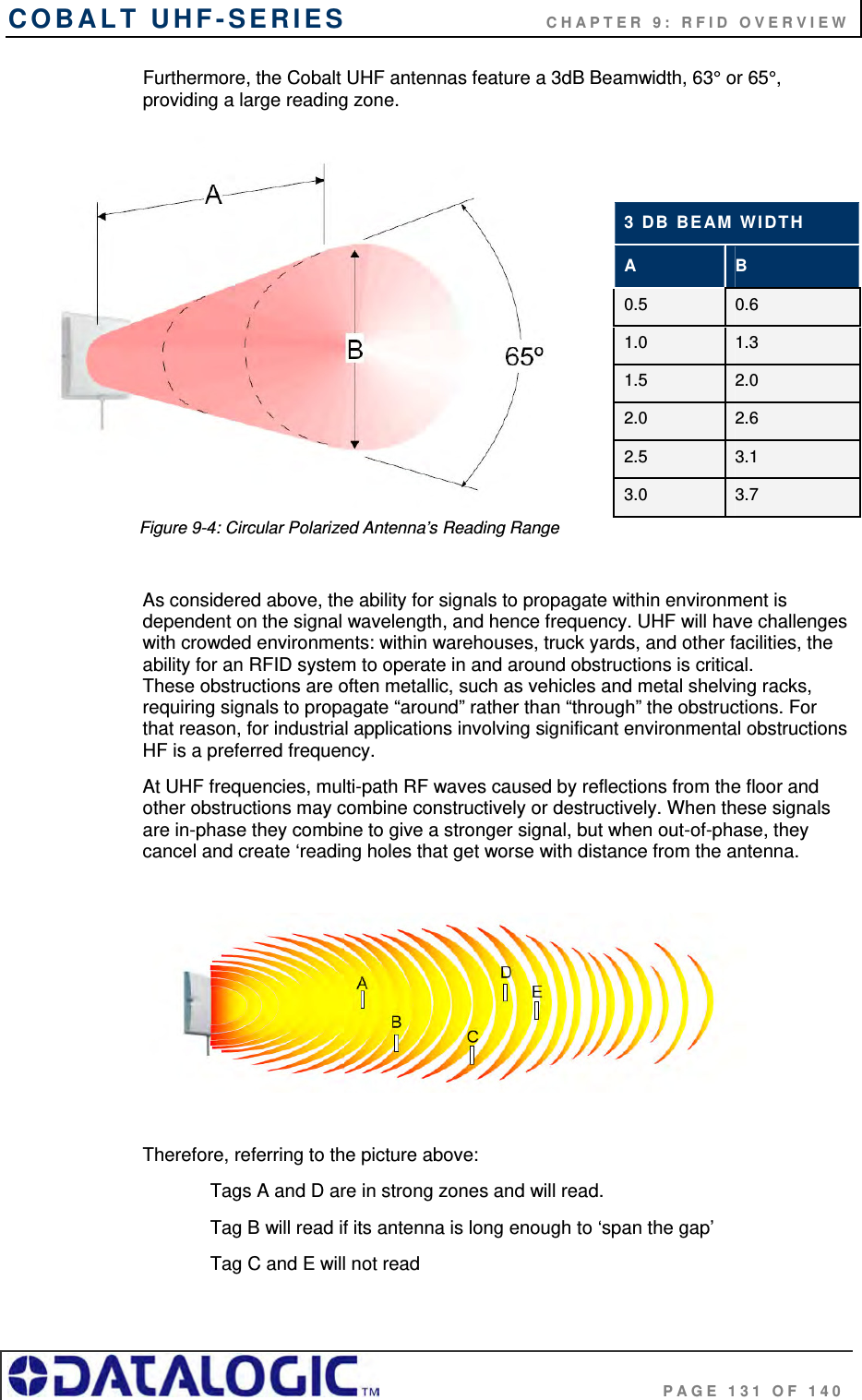
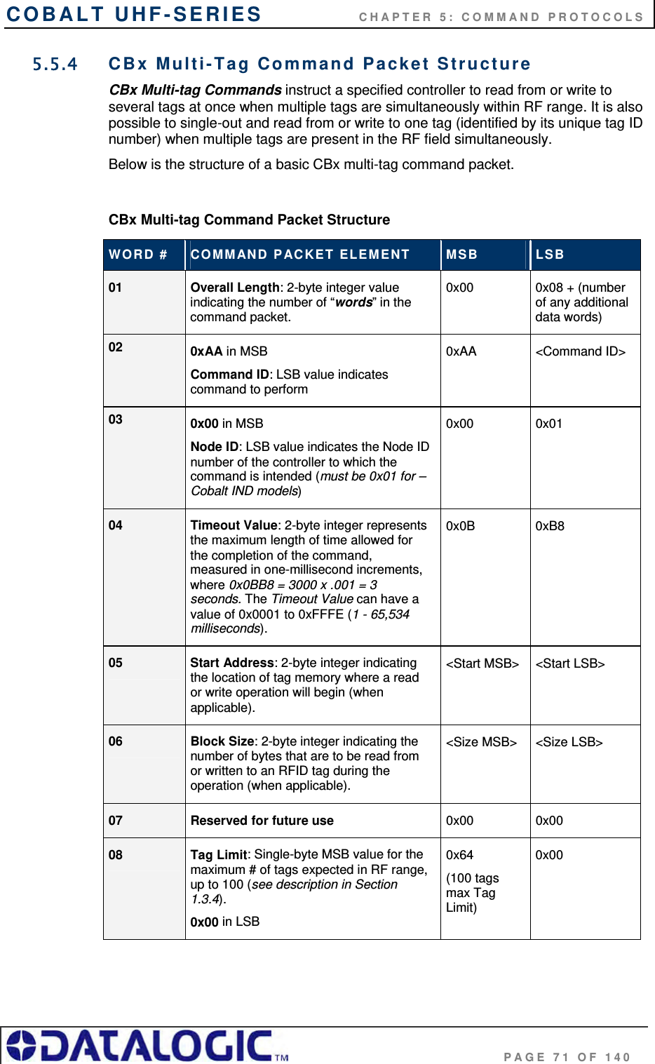
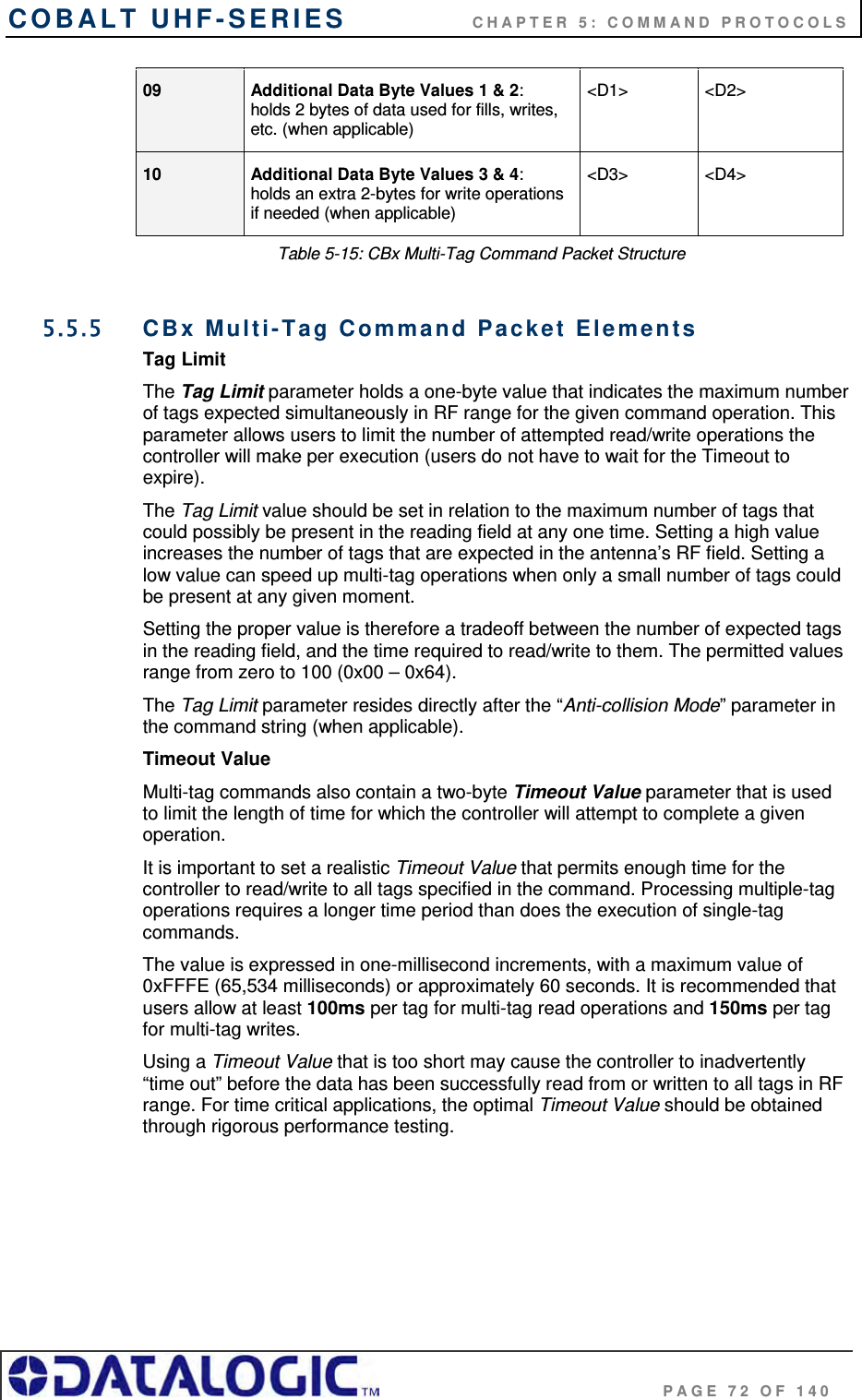
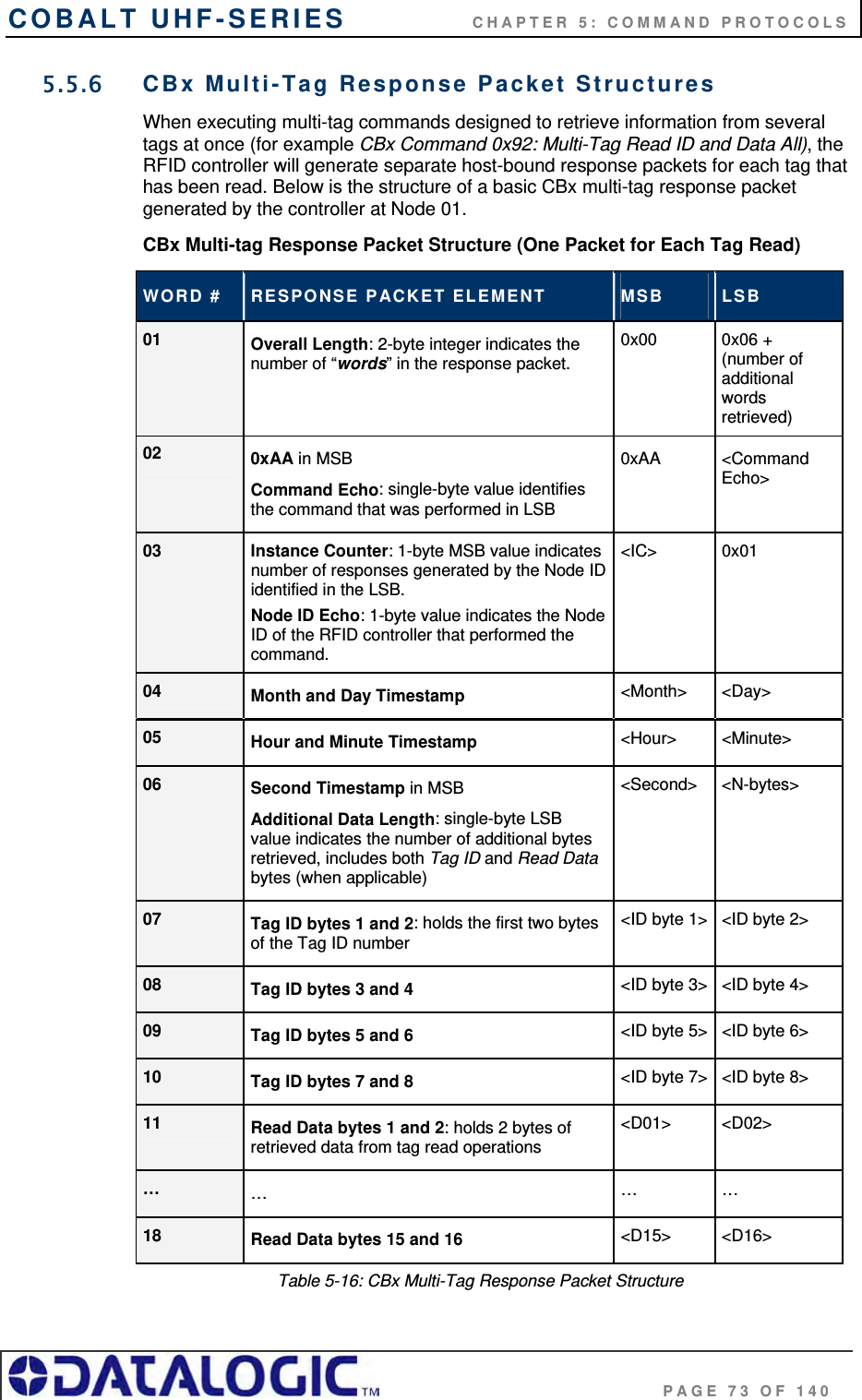
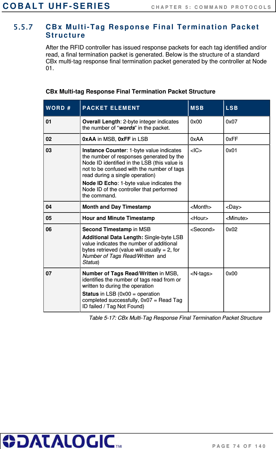
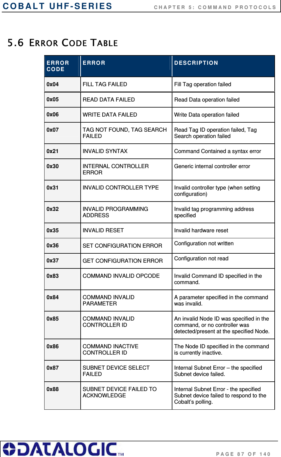
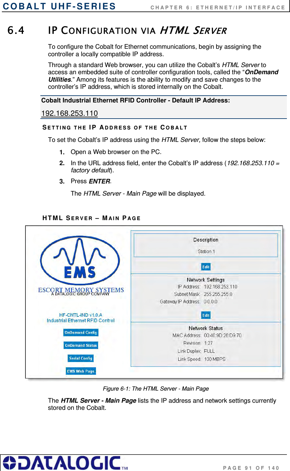
![COBALT UHF-SERIES CHAPTER 5: COMMAND PROTOCOLS PAGE 49 OF 140 5.3 ABX COMMAND PROTOCOL OVERVIEW There are two versions of the ABx Command Protocol that are supported by the Cobalt UHF Serial Controller, they are: ABx Fast (default) ABx Standard The ABx Fast Command Protocol has a single-byte based packet structure that permits the execution of RFID commands while requiring the transfer of fewer total bytes than ABx Standard. ABx Fast is the default command protocol used by Cobalt UHF Serial RFID Controller. It can be used with or without a checksum byte. The ABx Standard Command Protocol uses a double-byte, word based format that shares a common syntax with most existing RFID systems produced by Escort Memory Systems. This protocol offers legacy support, which may be required by existing PLC applications that only support a 2-byte word packet format. If your application requires compatibility with existing or legacy RFID devices from Datalogic’s EMS product line, use ABx Standard. ABx Standard does not support the use of a checksum byte. NOTE: By default, the UHF-CNTL-232-02 is configured to use the ABx Fast Command Protocol. ABx Fast (as the name suggests) is the faster and more efficient of the two ABx protocols, offering increased communication speed and error immunity. 5.3.1 ABx Command Packet Structure All ABx-based RFID commands contain certain fundamental packet elements, including a Command Header, a Command ID, one or more Command Parameters (when applicable) and a Command Terminator. Command Packet Structure = [Command Header + Command ID + Command Parameters + Command Terminator] 5.3.2 ABx Protocols - Headers and Terminators In ABx Standard, commands begin with the one-byte command header "0xAA," and end with the two-byte command terminator "0xFF, 0xFF". In ABx Fast, commands begin with the two-byte command header “0x02, 0x02” and end with the one-byte command terminator “0x03.” See the table below for further clarification. ABx Protocols - Headers and Terminators ABX PROTOCOL HEADER TERMINATOR ABx Fast 0x02, 0x02 0x03 ABx Standard 0xAA 0xFF, 0xFF Table 5-4: ABx Protocols - Headers and Terminators](https://usermanual.wiki/Balluff/UHF-CNTL-02/User-Guide-1120367-Page-49.png)
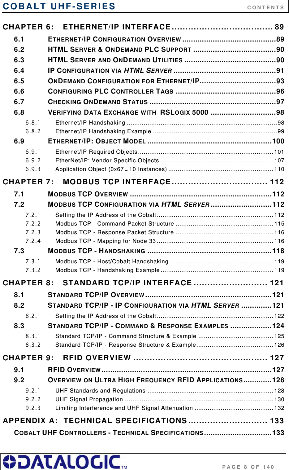
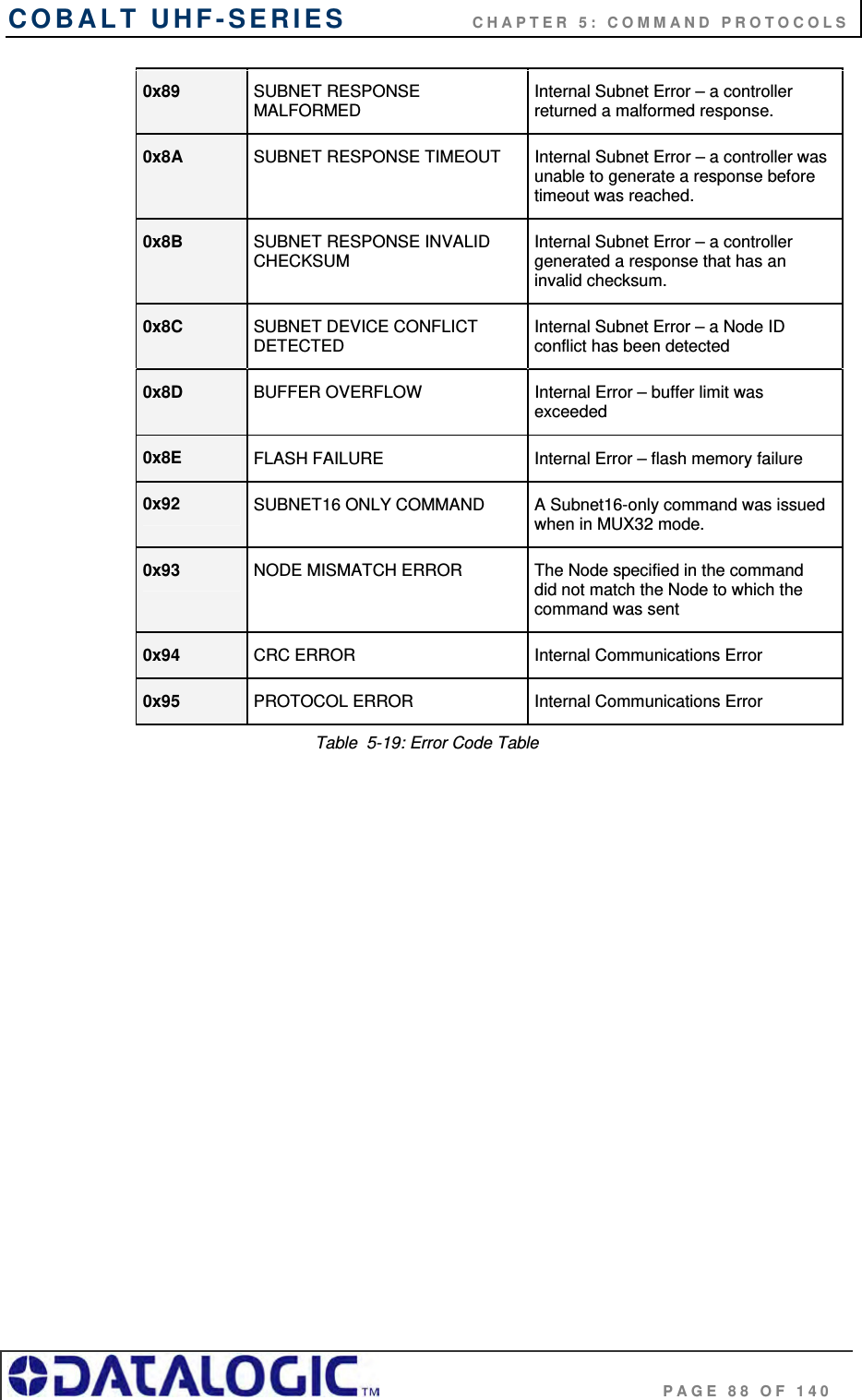
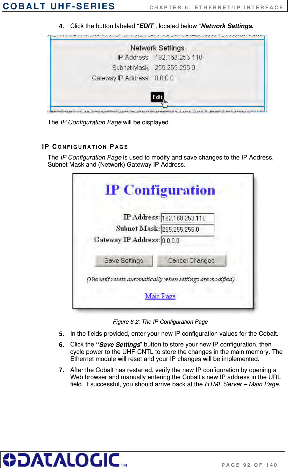
![COBALT UHF-SERIES CHAPTER 5: COMMAND PROTOCOLS PAGE 50 OF 140 When a command is issued by the host, the RFID controller stores the incoming data packet in a buffer while it scans the data for a start character (0x02, 0x02 or 0xAA). When a start character is found, it checks for the proper terminator (0x03 or 0xFF, 0xFF). Having identified a potentially valid command string, the controller will verify the format of the data and either perform the requested function or generate an error message. 5.3.3 ABx Response Packet Structure After completing an ABx command, the RFID controller generates a host-bound, response packet that indicates the status and/or results of the attempted command. The response packet structure for all ABx protocols consists of a Response Header, a Command Echo, one or more Response Values (when applicable), and a Response Terminator. Response Packet Structure = [Response Header + Command Echo + Response Values + Response Terminator] Note that, for each ABx protocol, response header and response terminator parameters are the same as their command header and command terminator counterparts. ATTENTION: This Cobalt UHF Series Manual does NOT contain descriptions or examples of each supported RFID command common to all the devices in the Cobalt family. For complete details regarding the use of common RFID commands please visit www.ems-rfid.com and download the ABx Standard Command Protocol – Reference Manual or the ABx Fast Command Protocol – Reference Manual. Here you will find only the commands that are specific to the UHF controller.](https://usermanual.wiki/Balluff/UHF-CNTL-02/User-Guide-1120367-Page-50.png)
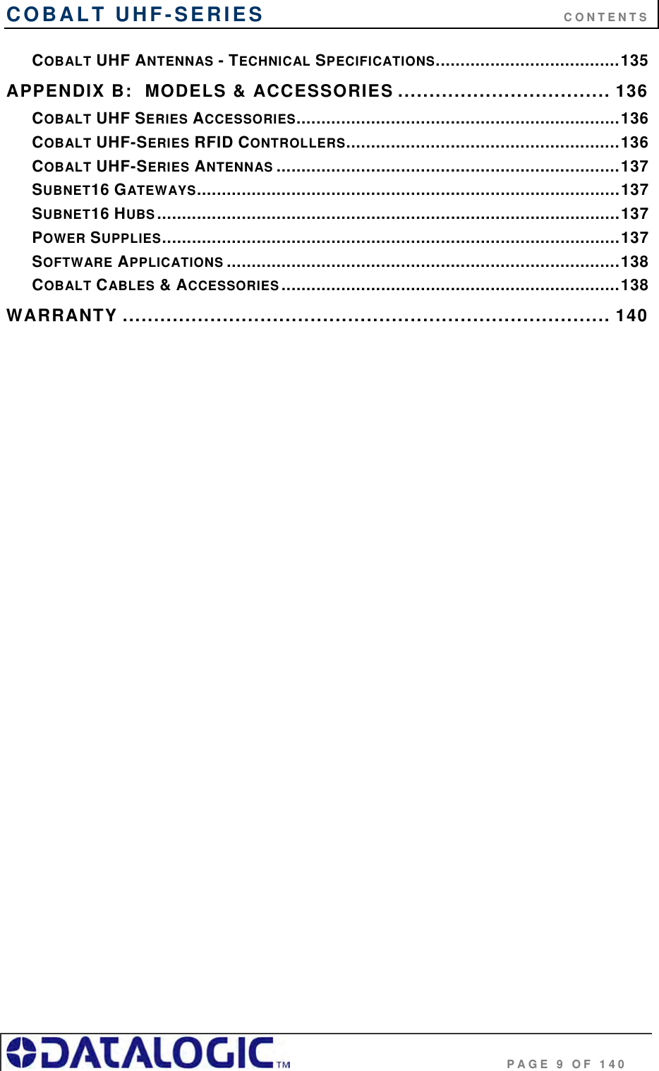
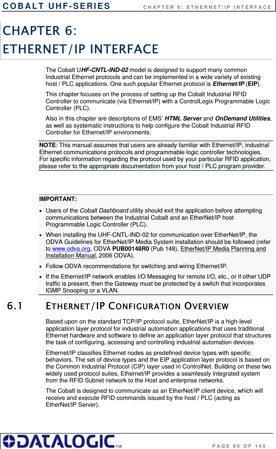
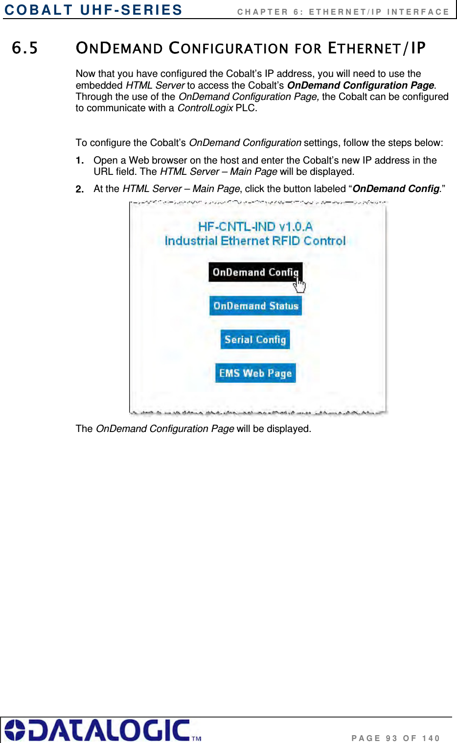
![COBALT UHF-SERIES CHAPTER 5: COMMAND PROTOCOLS PAGE 55 OF 140 CHECKSUM EXAMPLE The following example depicts Command 0x05 (Read Data) when using a Checksum. COMMAND ELEMENT CONTENTS USED IN CHECKSUM Header 0x02, 0x02 n/a Command Size 0x0007 0x00, 0x07 Command ID 0x05 0x05 Start Address 0x0001 0x00, 0x01 Block Size 0x0004 0x00, 0x04 Timeout Value 0x07D0 0x07, 0xD0 Checksum 0x17 n/a Terminator 0x03 n/a Table 5-8: ABx Fast - Checksum Example Add the byte values from the Command Size, Command ID, Start Address, Block Size and Timeout Value parameters together and subtract from 0xFF. The resulting value will be the Checksum. [0x07 + 0x05 + 0x01 + 0x04 + 0x07 + 0xD0] = 0xE8 The checksum equation is: [0xFF – 0xE8] = 0x17 Checksum = [0xFF – (sum of these fields)]](https://usermanual.wiki/Balluff/UHF-CNTL-02/User-Guide-1120367-Page-55.png)
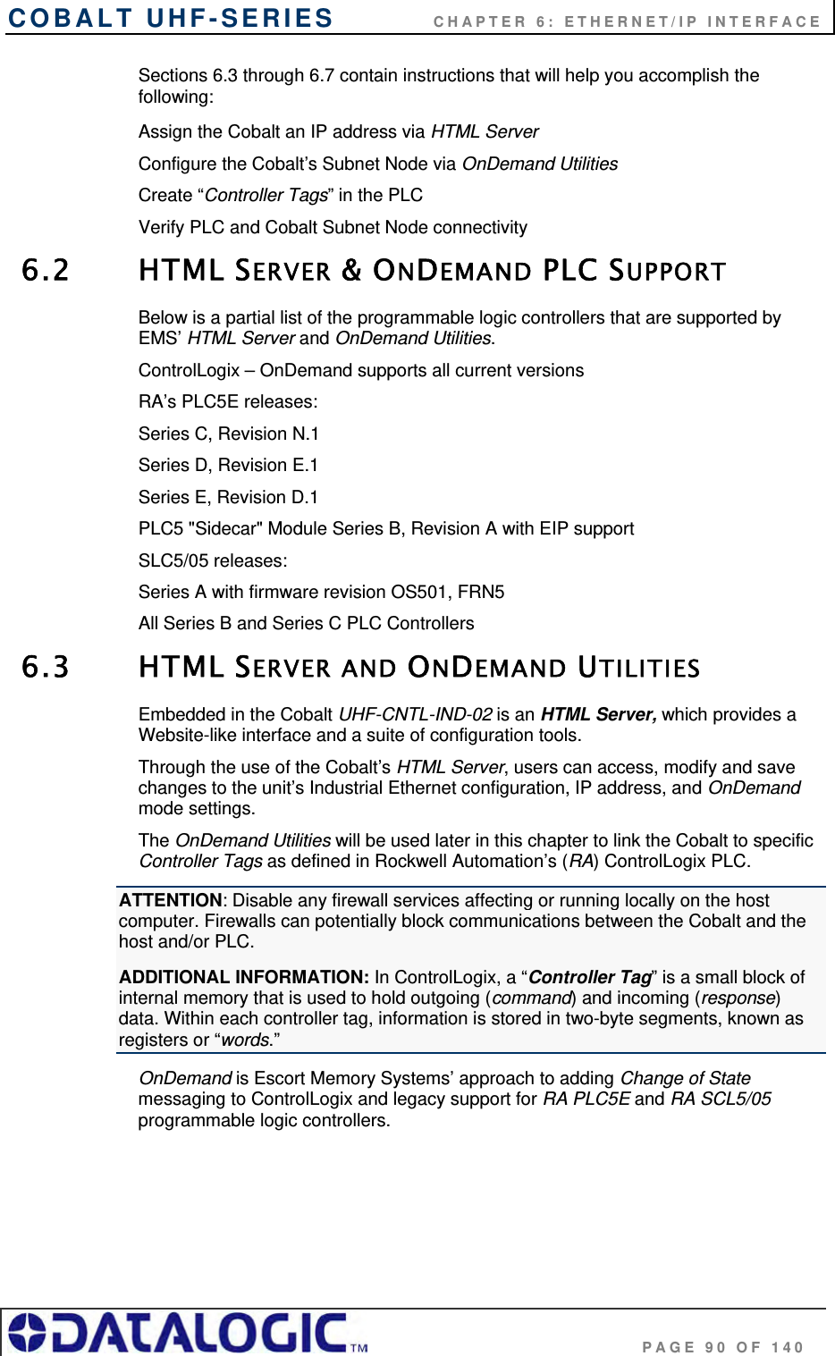
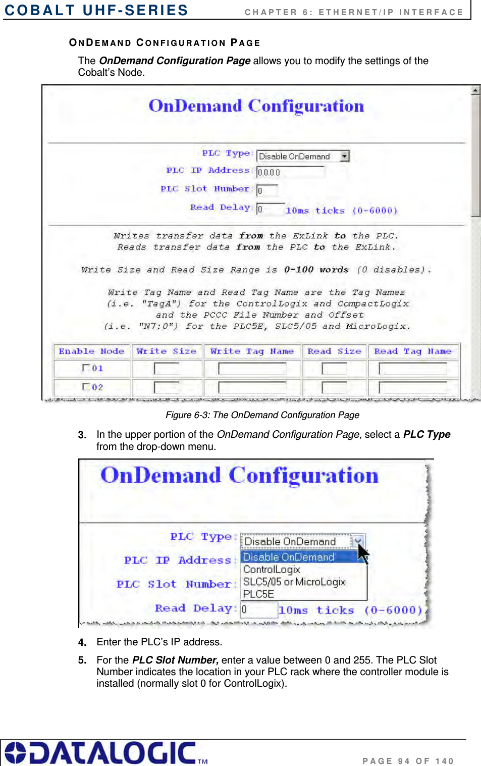
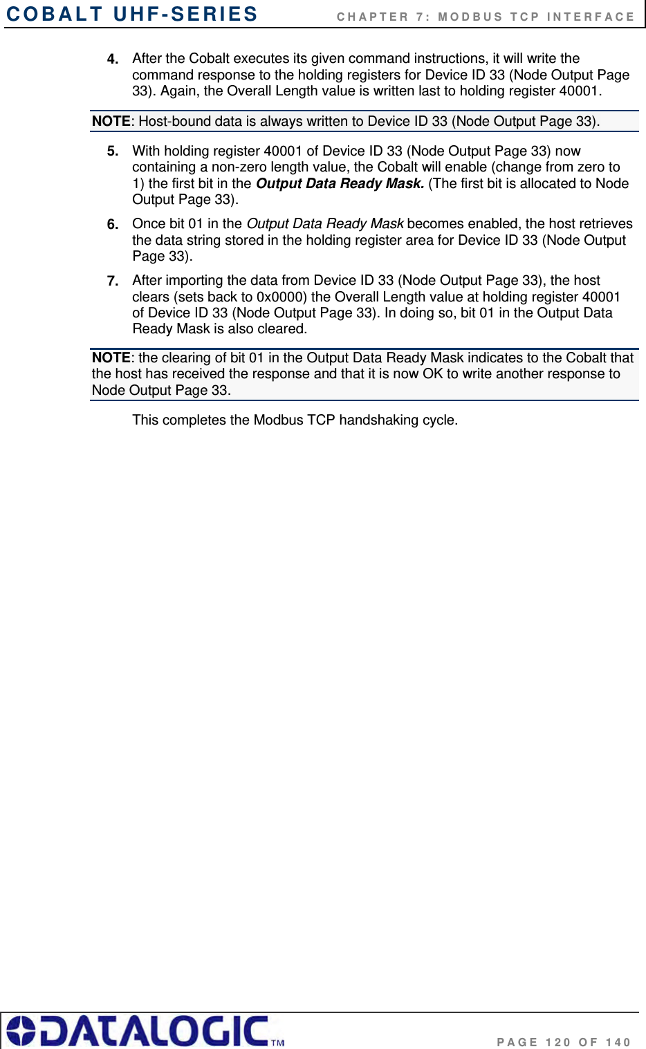
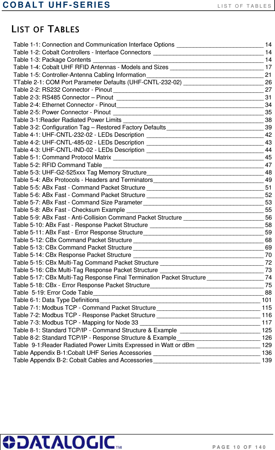
![COBALT UHF-SERIES CHAPTER 6: ETHERNET/IP INTERFACE PAGE 99 OF 140 6.8.2 Ethernet/IP Handshaking Example In the example below, EMS_READ1 is the name of the Read Tag and EMS_WRITE1 is the name of the Write Tag. NOTE: [0] indicates the first word, [1] indicates the second word in a controller tag. 1. The PLC writes the command to the Read Tag (EMS_READ1) and then increments the counter in EMS_READ1 [1] 2. The counter in EMS_READ1 [1] is copied by the Cobalt to EMS_WRITE1 [0] which acknowledges that the command has been received. 3. Following execution of the command, the Cobalt copies the response to EMS_WRITE1 (the Write Tag) and increments the counter in EMS_WRITE1 [1]. This signals that there is new data for the PLC (the Cobalt generated response, in this case). WRITE TAG (where responses are written by the Cobalt) EMS_Write1 [0] = (2) the Cobalt copies counter here to ACK EMS_Write1 [1] = (3) the Cobalt increments this counter to signal response available EMS_Write1 [2] = Data Size EMS_Write1 [3-102] = Data READ TAG (where commands are retrieved by the Cobalt) EMS_Read1 [0] = (4) PLC copies the counter here to ACK the response EMS_Read1 [1] = (1) PLC increments this counter after writing a command EMS_Read1 [2] = Data Size EMS_Read1 [3-102] = Data](https://usermanual.wiki/Balluff/UHF-CNTL-02/User-Guide-1120367-Page-99.png)
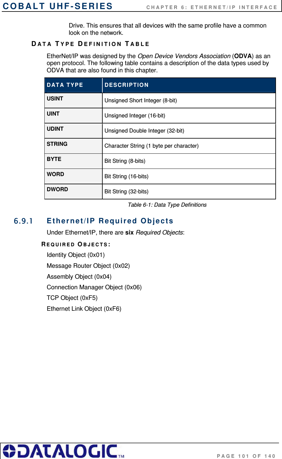
![COBALT UHF-SERIES CHAPTER 6: ETHERNET/IP INTERFACE PAGE 100 OF 140 4. After the PLC has processed the response information, it copies the counter from EMS_WRITE1 [1] to EMS_READ1 [0] which signals to the Cobalt that the PLC has retrieved the response data. 5. The data will then be cleared from EMS_WRITE1. After which the Cobalt will be ready to receive another command. 6.9 ETHERNET/IP: OBJECT MODEL The Object Model is the logical organization of attributes (parameters) within classes (objects) and services supported by each device. Objects are broken down into three categories: Required Objects, Vendor Specific Objects and Application Objects. Required Objects are classes that must be supported by all devices on EtherNet/IP. The Cobalt has six Required Objects. Vendor Specific Objects are classes that add attributes and services that do not fit into the Required Objects or Application Objects categories. The Cobalt has two Vendor Specific Objects. Application Objects are classes that must be supported by all devices using the same profile. An example of a profile is a Discrete I/O device or an AC](https://usermanual.wiki/Balluff/UHF-CNTL-02/User-Guide-1120367-Page-100.png)
![COBALT UHF-SERIES CHAPTER 6: ETHERNET/IP INTERFACE PAGE 102 OF 140 IDENTITY OBJECT (0X01 - 1 INSTANCE) Class Attributes Attribute ID Name / Description Data Type Default Data Value Access Rule 1 Revision UINT 1 Get Instance Attributes Attribute ID Name / Description Data Type Default Data Value Access Rule 1 Vendor Number UINT 50 DEC Get 2 Device Type UINT 0x0C Get 3 Product Code Number UINT 6102 DEC Get 4 Product Major Revision Product Minor Revision USINT USINT 01 25 Get 5 Status Word (see below for definition) WORD See Below Get 6 Serial Number UDINT Unique 32 Bit Value Get 7 Product Name: Product Name Size Product Name String USINT USINT[26] HF-CNTL-IND-02 06 “Cobalt” Get Status Word Bit Bit = 0 Bit = 1 0 No I/O Connection I/O Connection Allocated 1 – 15 Unused Unused Common Services Implementation Service Code Class Level Instance Level Service Name 0x0E Yes Yes Get Attribute Single 0x05 No Yes Reset MESSAGE ROUTER OBJECT (0X02) This object has no supported attributes.](https://usermanual.wiki/Balluff/UHF-CNTL-02/User-Guide-1120367-Page-102.png)
![COBALT UHF-SERIES CHAPTER 6: ETHERNET/IP INTERFACE PAGE 103 OF 140 ASSEMBLY OBJECT (0X04 - 3 INSTANCES) Class Attributes Attribute ID Name / Description Data Type Default Data Value Access Rule 1 Revision UINT 1 Get 2 Max Instance UINT 81 Get Instance 0x64 Attributes (Input Instance) Attribute ID Name / Description Data Type Default Data Value Access Rule Status Information: Bitmap of Consume Instances with Data DINT 0 3 Bitmap of Produce Instances with Data DINT 0 Get User Datagram Protocol (UDP) I/O Sequence Number Handshaking The data producing device increments the data sequence number by one with the transmission of each new serial data packet. Valid sequence numbers are 1-65535. After the consuming device has processed the data, it must echo the sequence number in the handshake to allow the producing device to remove the data from the queue. This is required for I/O communications because UDP is not guaranteed to arrive in order. If the Node ID number is passed as part of the I/O message, the message is stored to the appropriate location in the Modbus RTU table. Because communications are asynchronous, the Node ID number is also stored as part of the output data. It is the responsibility of the PLC programmer to make sure the proper request lines up with the proper response if the Cobalt is used as a request/response device. Instance 0x65 Attributes (Input Instance 2) Attribute ID Name / Description Data Type Default Data Value Access Rule Serial Produce Data: Consume Data Seq. Number Handshake UINT 0 Produce Data Sequence Number UINT 0 Node 1 Serial Produce Data Size UINT 0 3 Node 1 Serial Produce Data WORD[100] All 0’s Get](https://usermanual.wiki/Balluff/UHF-CNTL-02/User-Guide-1120367-Page-103.png)
![COBALT UHF-SERIES CHAPTER 6: ETHERNET/IP INTERFACE PAGE 104 OF 140 Instance 0x66 Attributes (Input Instance 3) Attribute ID Name / Description Data Type Default Data Value Access Rule Serial Produce Data: Consume Data Seq. Number Handshake UINT 0 Produce Data Sequence Number UINT 0 Node ID (1-32) UINT 1 Node Serial Produce Data Size UINT 0 3 Node Serial Produce Data WORD[100] All 0’s Get Instance 0x70 Attributes (Output Instance 1) Attribute ID Name / Description Data Type Default Data Value Access Rule Serial Consume Data: Produce Data Seq. Number Handshake UINT 0 Consume Data Sequence Number UINT 0 Node 1 Serial Consume Data Size UINT 0 3 Node 1 Serial Consume Data WORD[100] All 0’s Get / Set Instance 0x71 Attributes (Output Instance 2) Attribute ID Name / Description Data Type Default Data Value Access Rule Serial Consume Data: Produce Data Seq. Number Handshake UINT 0 Consume Data Sequence Number UINT 0 Node ID (1-32) UINT 1 Node Serial Consume Data Size UINT 0 3 Node Serial Consume Data WORD[100] All 0’s Get / Set Instance 0x80 Attributes (Configuration Instance) Most I/O clients include a configuration path when opening an I/O connection to a server. There is no configuration data needed.](https://usermanual.wiki/Balluff/UHF-CNTL-02/User-Guide-1120367-Page-104.png)
![COBALT UHF-SERIES CHAPTER 6: ETHERNET/IP INTERFACE PAGE 106 OF 140 6 Host Name* Structure of: Host Name Size Host Name UINT STRING 0 0 Get *See section 5-3.2.2.1 – 5-3.2.2.6 of “Volume 2: EtherNet/IP Adaptation of CIP” from ODVA for more information regarding these attributes. Common Services Implementation Service Code Class Level Instance Level Service Name 0x0E Yes Yes Get Attribute Single ETHERNET LINK OBJECT (0XF6 - 1 INSTANCE) Class Attributes Attribute ID Name / Description Data Type Default Data Value Access Rule 1 Revision UINT 1 Get Instance Attributes Attribute ID Name / Description Data Type Default Data Value Access Rule 1 Interface Speed* UDINT 100 Get 2 Interface Flags* DWORD 3 Get 3 Physical Address* USINT Array[6] 0 Get *See section 5-4.2.2.1 – 5-4.2.2.3 of “Volume 2: EtherNet/IP Adaptation of CIP” from ODVA for more details on this attribute. Common Services Implementation Service Code Class Level Instance Level Service Name 0x0E Yes Yes Get Attribute Single](https://usermanual.wiki/Balluff/UHF-CNTL-02/User-Guide-1120367-Page-106.png)
![COBALT UHF-SERIES CHAPTER 6: ETHERNET/IP INTERFACE PAGE 107 OF 140 6.9.2 EtherNet/IP: Vendor Specific Objects The Cobalt has two Vendor Specific Objects: VENDOR SPECIFIC OBJECTS: Cobalt Consume Data Object (0x64) Cobalt Produce Data Object (0x65) COBALT CONSUME DATA OBJECT (0X64 - 32 INSTANCES) Class Attributes (Instance 0) Attribute ID Name / Description Data Type Default Data Value Access Rule 1 Revision UINT 1 Get 2 Maximum Consume Data Buffer Size (in words) UINT 32768 Get 3 Bitmap of Consume Instances with Data Bit 0: Instance 1 … Bit 31: Instance 32 DINT 0 Get Instance Attributes (Instances 1-32) Attribute ID Name / Description Data Type Default Data Value Access Rule 1 Consume Data Size (in words) UINT 0 Get / Set 2 Consume Data [0-249] UINT 0 Get / Set 3 Consume Data [250-499] UINT 0 Get / Set 4 Consume Data [500-749] UINT 0 Get / Set 5 Consume Data [750-999] UINT 0 Get / Set 6 Consume Data [1,000-1,249] UINT 0 Get / Set … … … … … 10 Consume Data [2,000-2,249] UINT 0 Get / Set … … … … … 34 Consume Data [8,000-8,249] UINT 0 Get / Set … … … … … 38 Consume Data [9,000-9,249] UINT 0 Get / Set … … … … … 42 Consume Data [10,000-10,249] UINT 0 Get / Set](https://usermanual.wiki/Balluff/UHF-CNTL-02/User-Guide-1120367-Page-107.png)
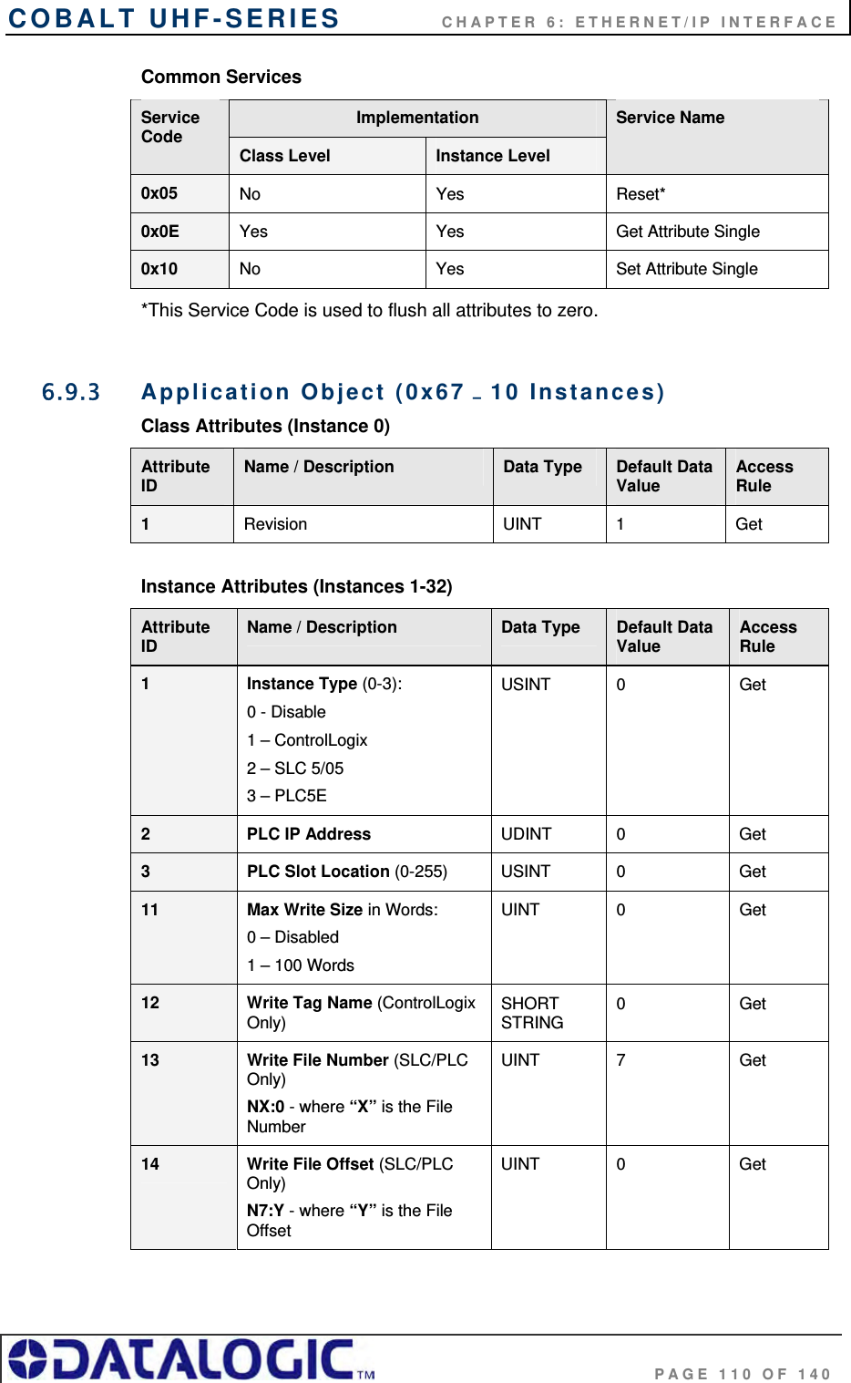
![COBALT UHF-SERIES CHAPTER 6: ETHERNET/IP INTERFACE PAGE 108 OF 140 … … … … … 82 Consume Data [20,000-20,249] UINT 0 Get / Set … … … … … 122 Consume Data [30,000-30,249] UINT 0 Get / Set … … … … … 126 Consume Data [31,000-31,249] UINT 0 Get / Set … … … … … 130 Consume Data [32,000-32,249] UINT 0 Get / Set 131 Consume Data [32,250-32,249] UINT 0 Get / Set 132 Consume Data [32,500-32,249] UINT 0 Get / Set 133 Consume Data [32,750-32,767] UINT 0 Get / Set Common Services Implementation Service Code Class Level Instance Level Service Name 0x05 No Yes Reset* 0x0E Yes Yes Get Attribute Single 0x10 No Yes Set Attribute Single *This Service Code is used to flush all attributes to zero. COBALT PRODUCE DATA OBJECT (0X65 - 32 INSTANCES) Class Attributes (Instance 0) Attribute ID Name / Description Data Type Default Data Value Access Rule 1 Revision UINT 1 Get 2 Maximum Produce Data Buffer Size (in words) UINT 32768 Get 3 Bitmap of Produce Instances with Data Bit 0: Instance 1 … Bit 31: Instance 32 DINT 0 Get](https://usermanual.wiki/Balluff/UHF-CNTL-02/User-Guide-1120367-Page-108.png)
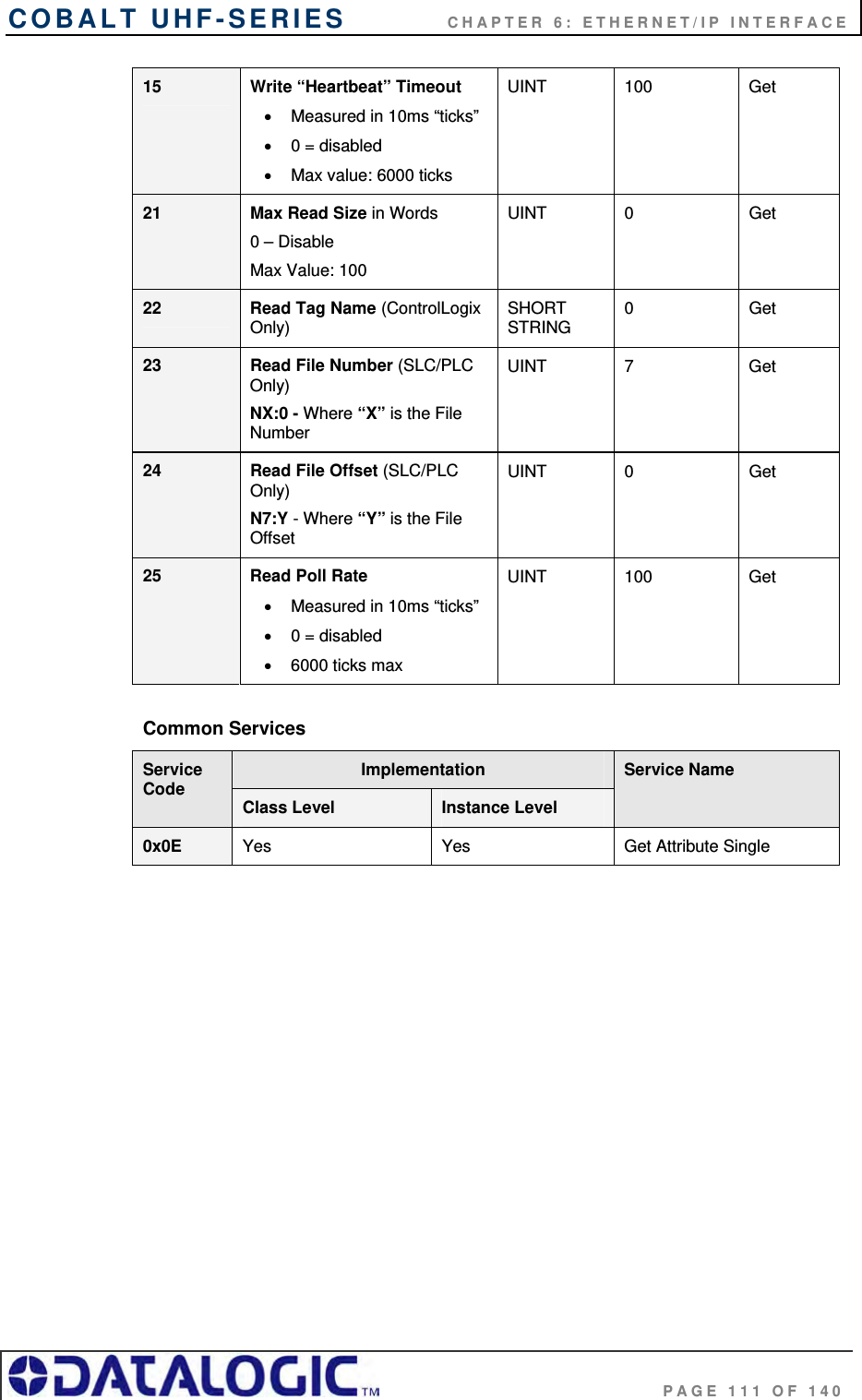
![COBALT UHF-SERIES CHAPTER 6: ETHERNET/IP INTERFACE PAGE 109 OF 140 Instance Attributes (Instances 1-32) Attribute ID Name / Description Data Type Default Data Value Access Rule 1 Produce Data Size (in words) UINT 0 Get / Set 2 Produce Data [0-249] UINT 0 Get 3 Produce Data [250-499] UINT 0 Get 4 Produce Data [500-749] UINT 0 Get 5 Produce Data [750-999] UINT 0 Get 6 Produce Data [1,000-1,249] UINT 0 Get … … … … … 10 Produce Data [2,000-2,249] UINT 0 Get … … … … … 34 Produce Data [8,000-8,249] UINT 0 Get … … … … … 38 Produce Data [9,000-9,249] UINT 0 Get … … … … … 42 Produce Data [10,000-10,249] UINT 0 Get … … … … … 82 Produce Data [20,000-20,249] UINT 0 Get … … … … … 122 Produce Data [30,000-30,249] UINT 0 Get … … … … … 126 Produce Data [31,000-31,249] UINT 0 Get … … … … … 130 Produce Data [32,000-32,249] UINT 0 Get 131 Produce Data [32,250-32,249] UINT 0 Get 132 Produce Data [32,500-32,249] UINT 0 Get 133 Produce Data [32,750-32,767] UINT 0 Get](https://usermanual.wiki/Balluff/UHF-CNTL-02/User-Guide-1120367-Page-109.png)