Bosch Automotive Service Solutions 576253 WiFi/BT Module Card User Manual Antenna list for Module Integration and antenna spec
Bosch Automotive Service Solutions Inc WiFi/BT Module Card Antenna list for Module Integration and antenna spec
Contents
- 1. User manual
- 2. Antenna list for Module Integration and antenna spec
- 3. User Manual
- 4. Antenna List for Module Integration and antennas spec
- 5. Users manual
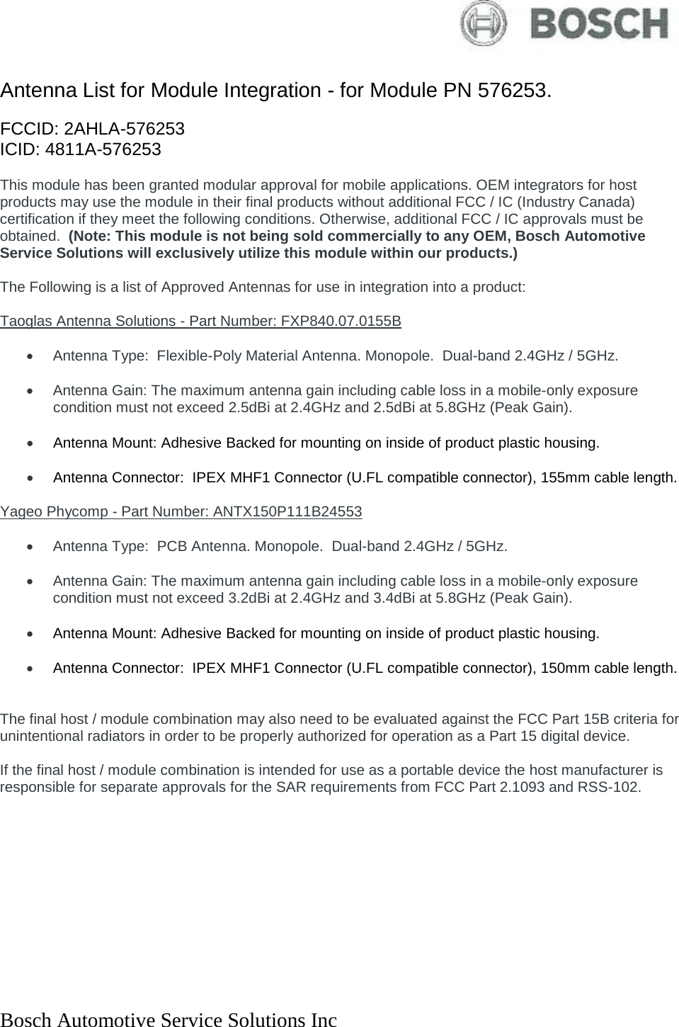
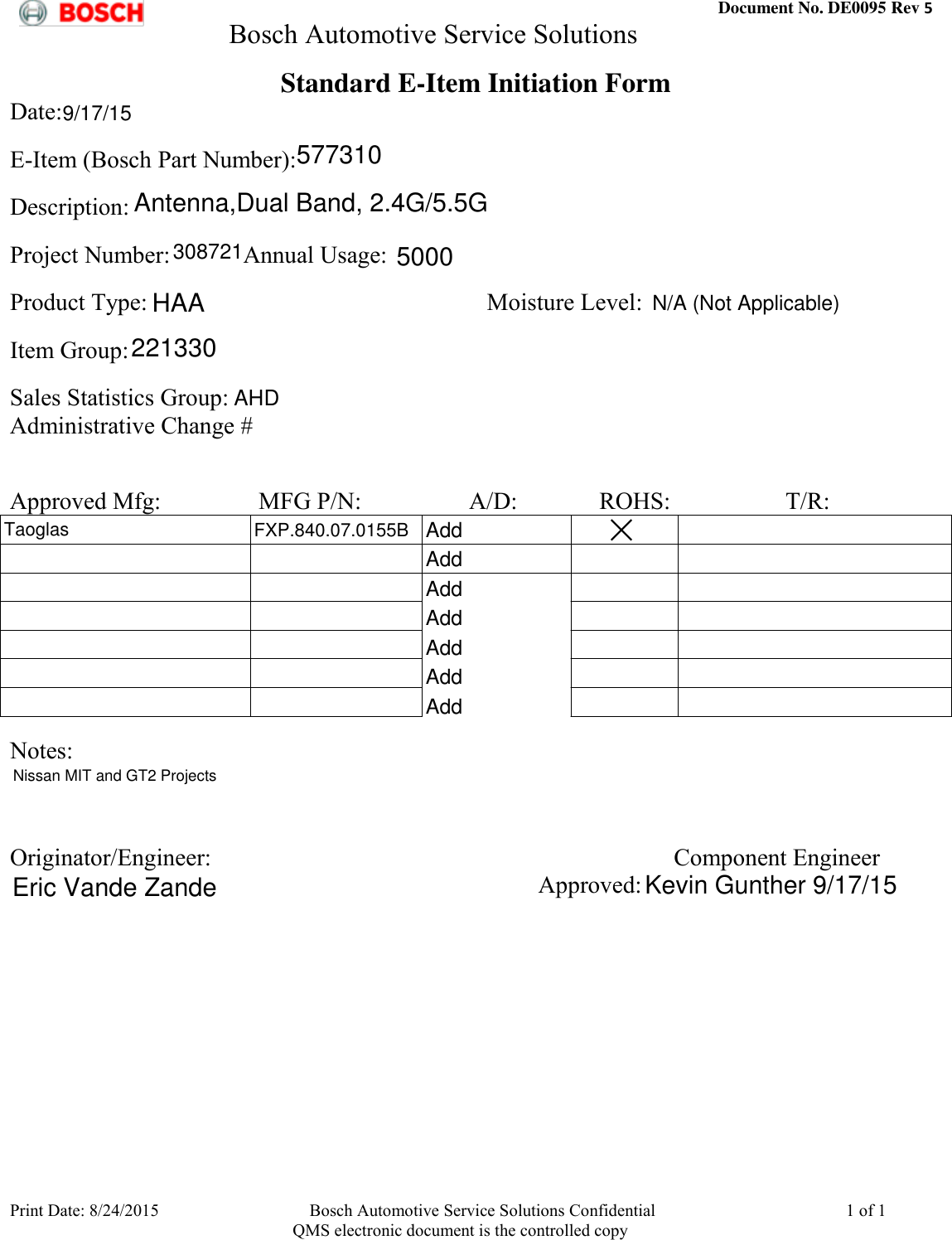
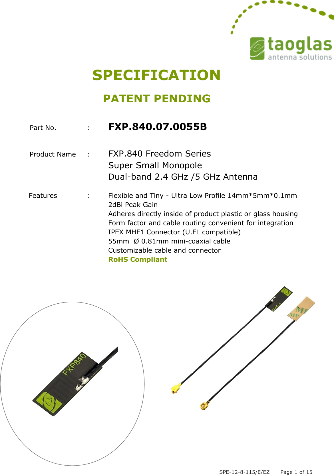
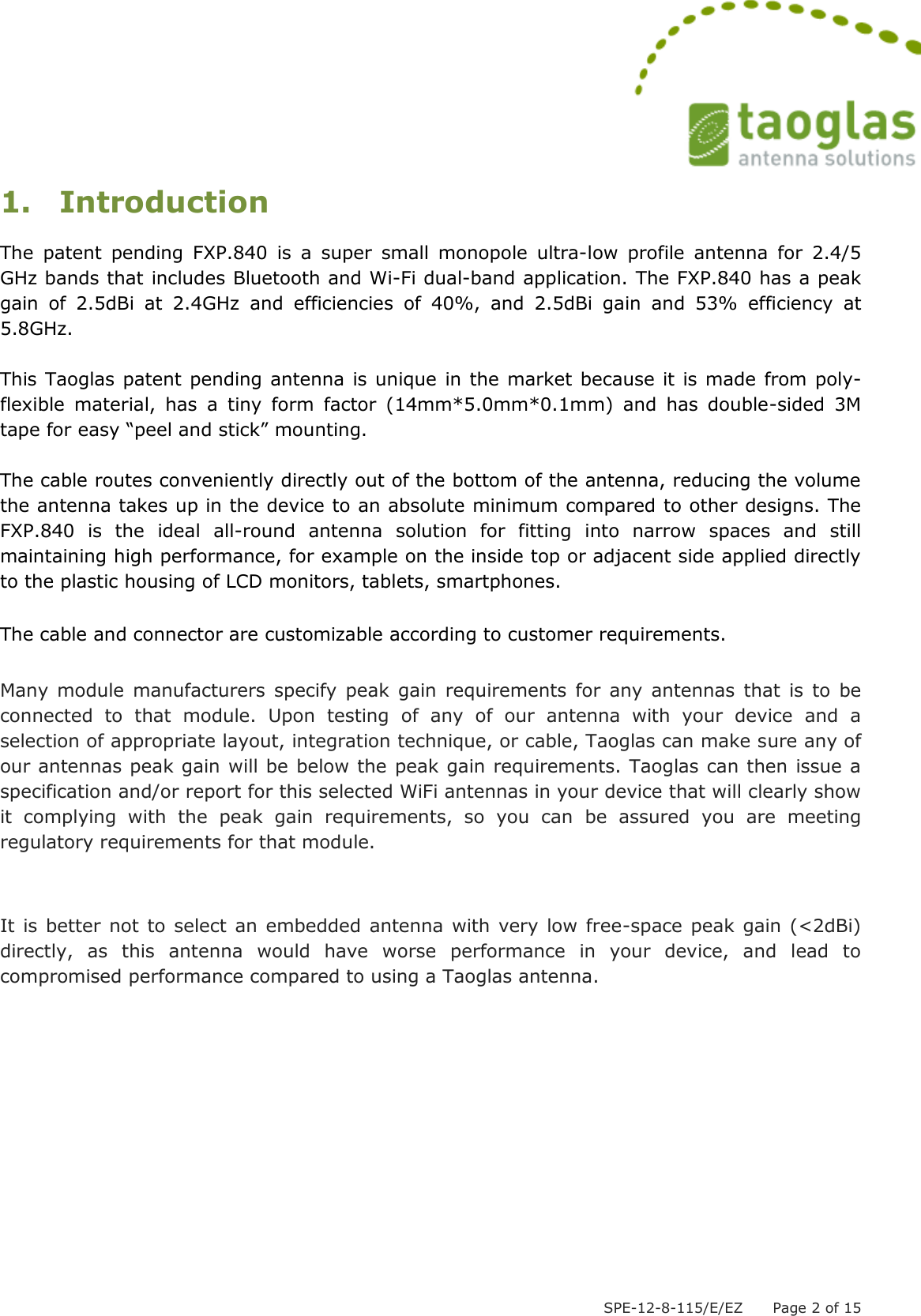
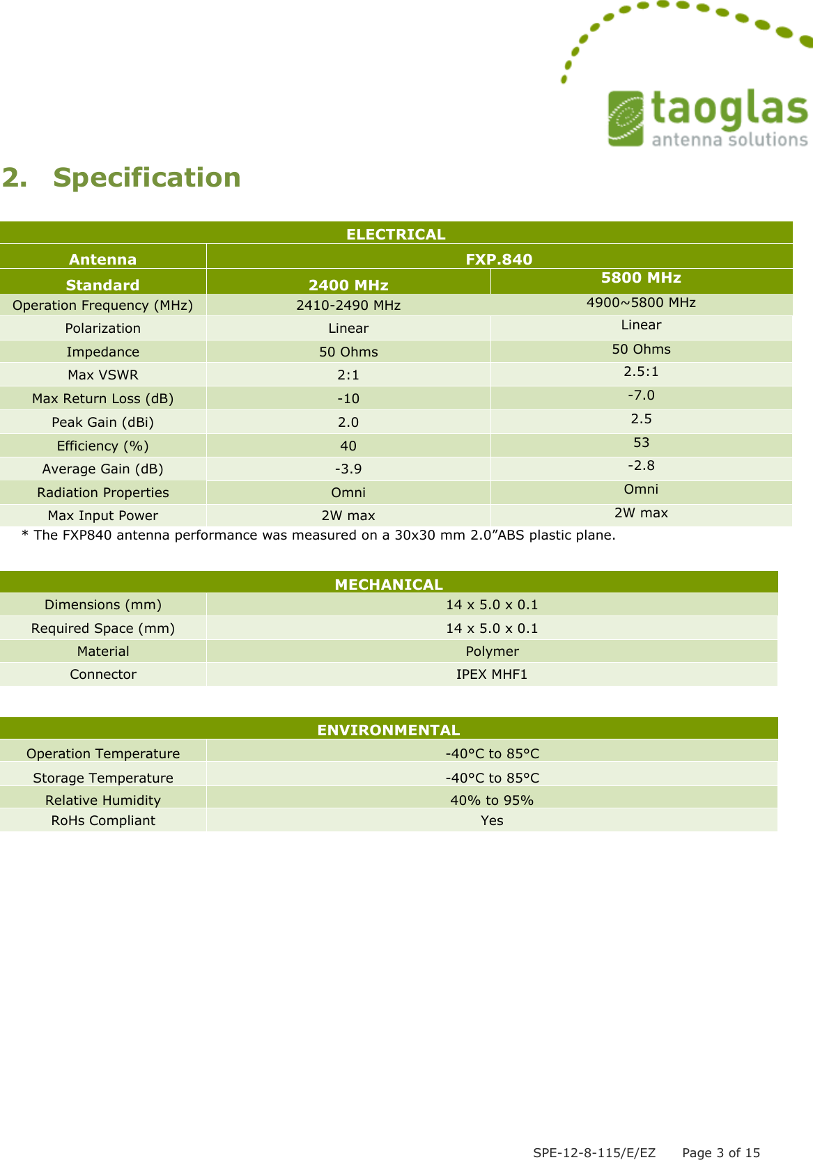
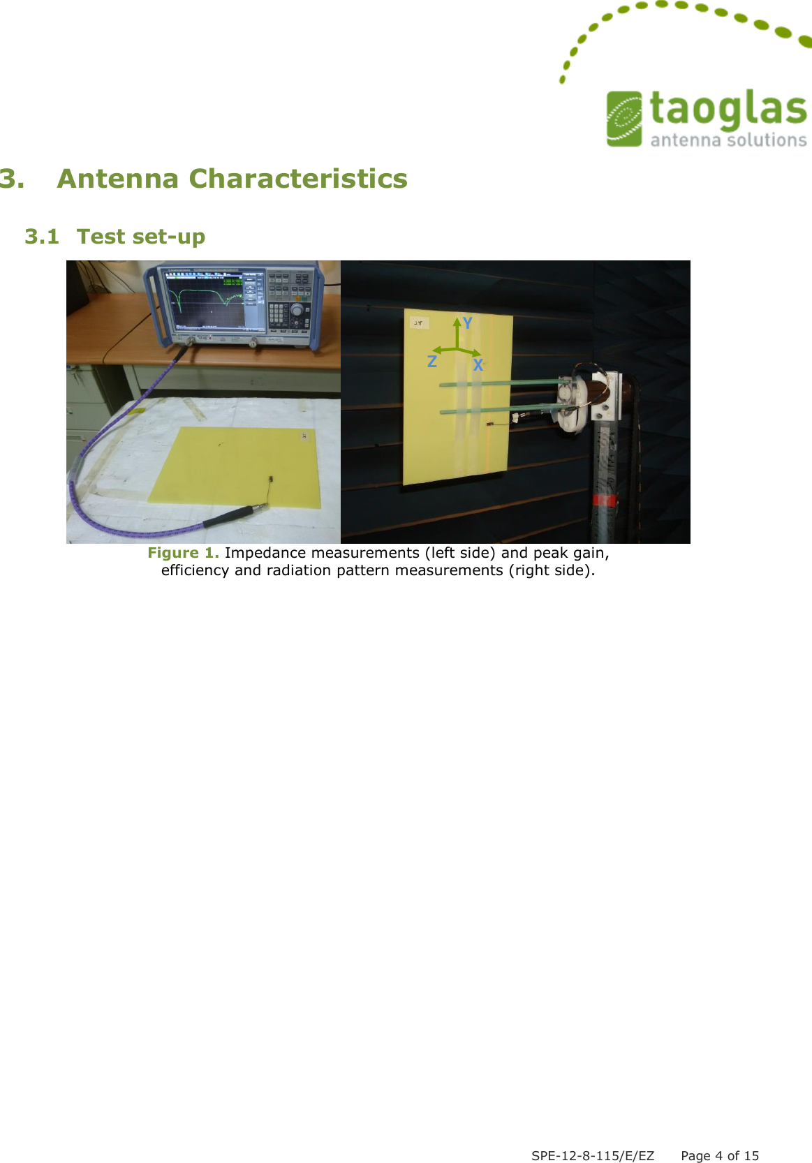
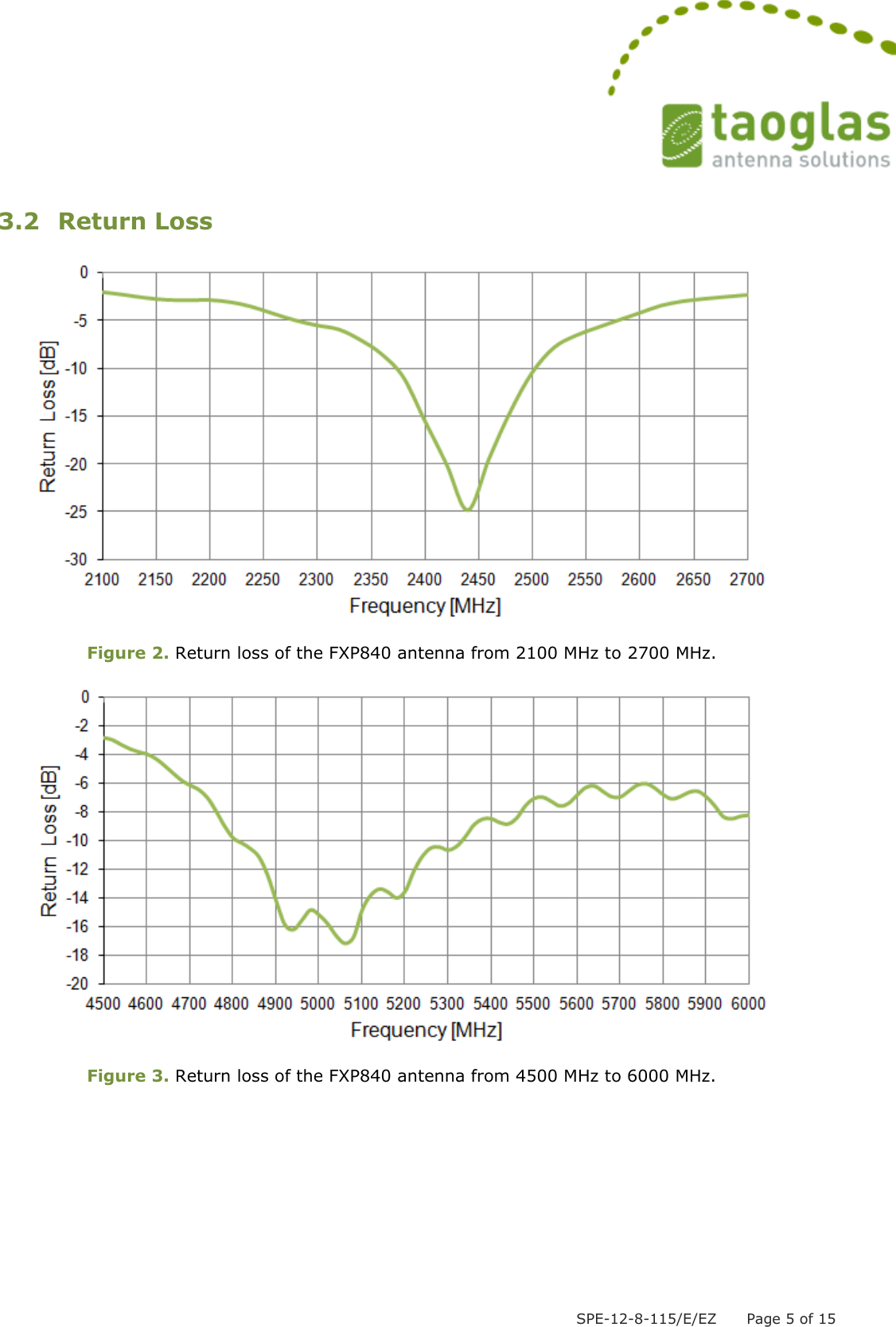
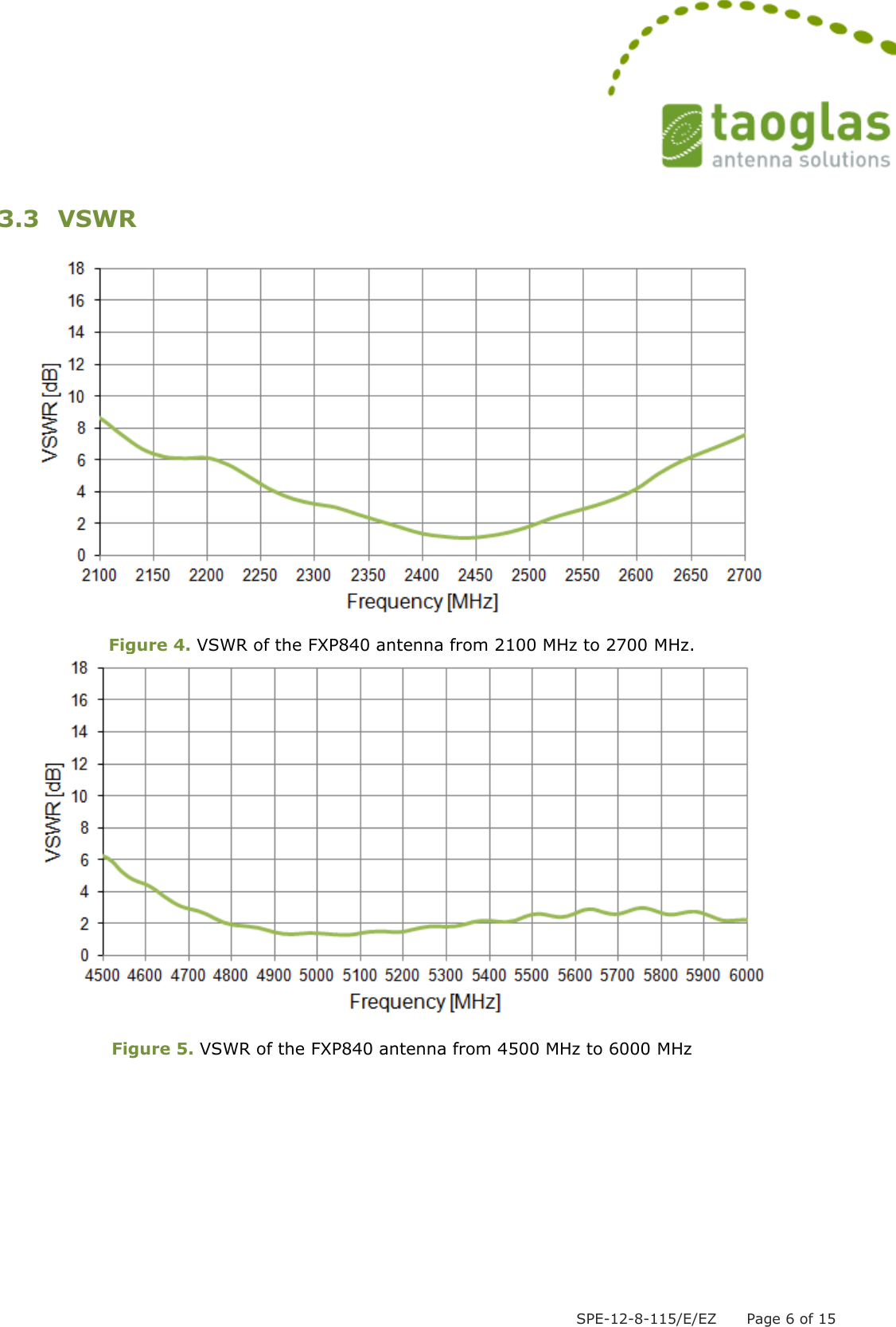
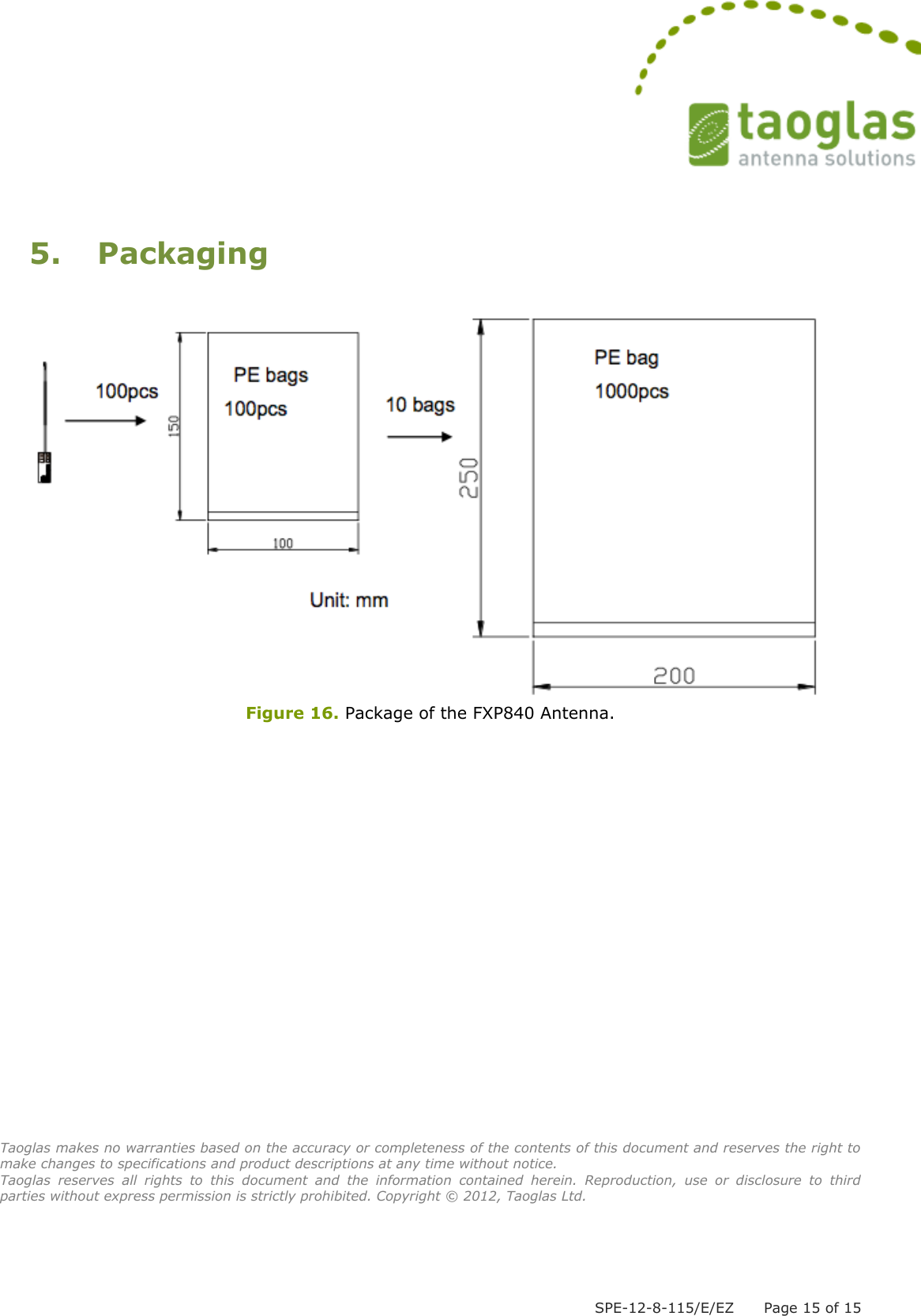
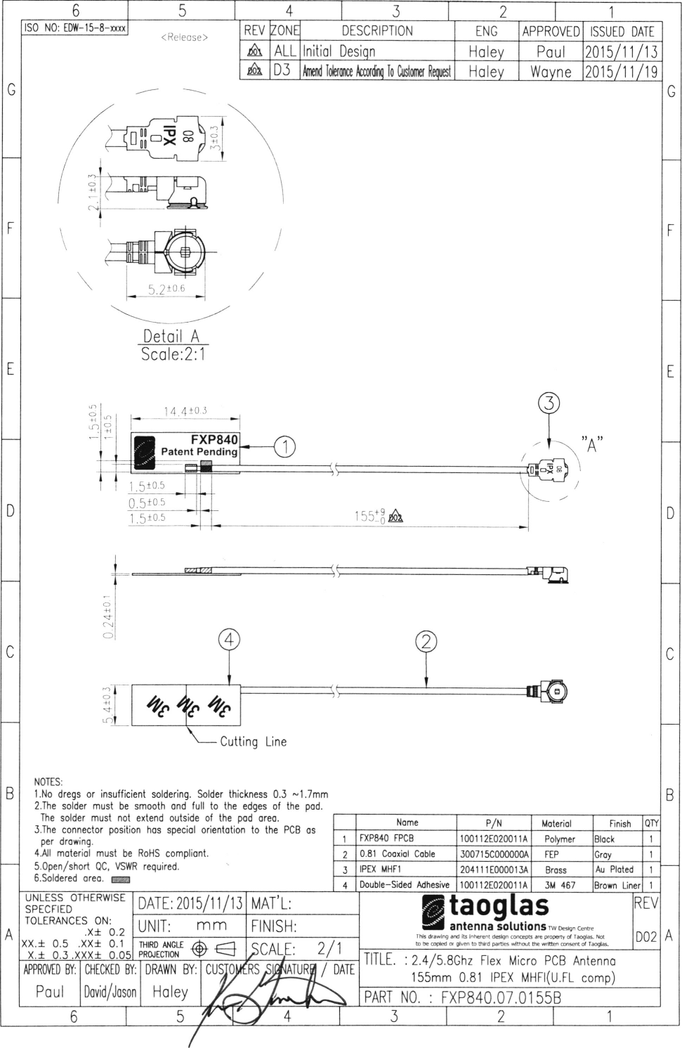
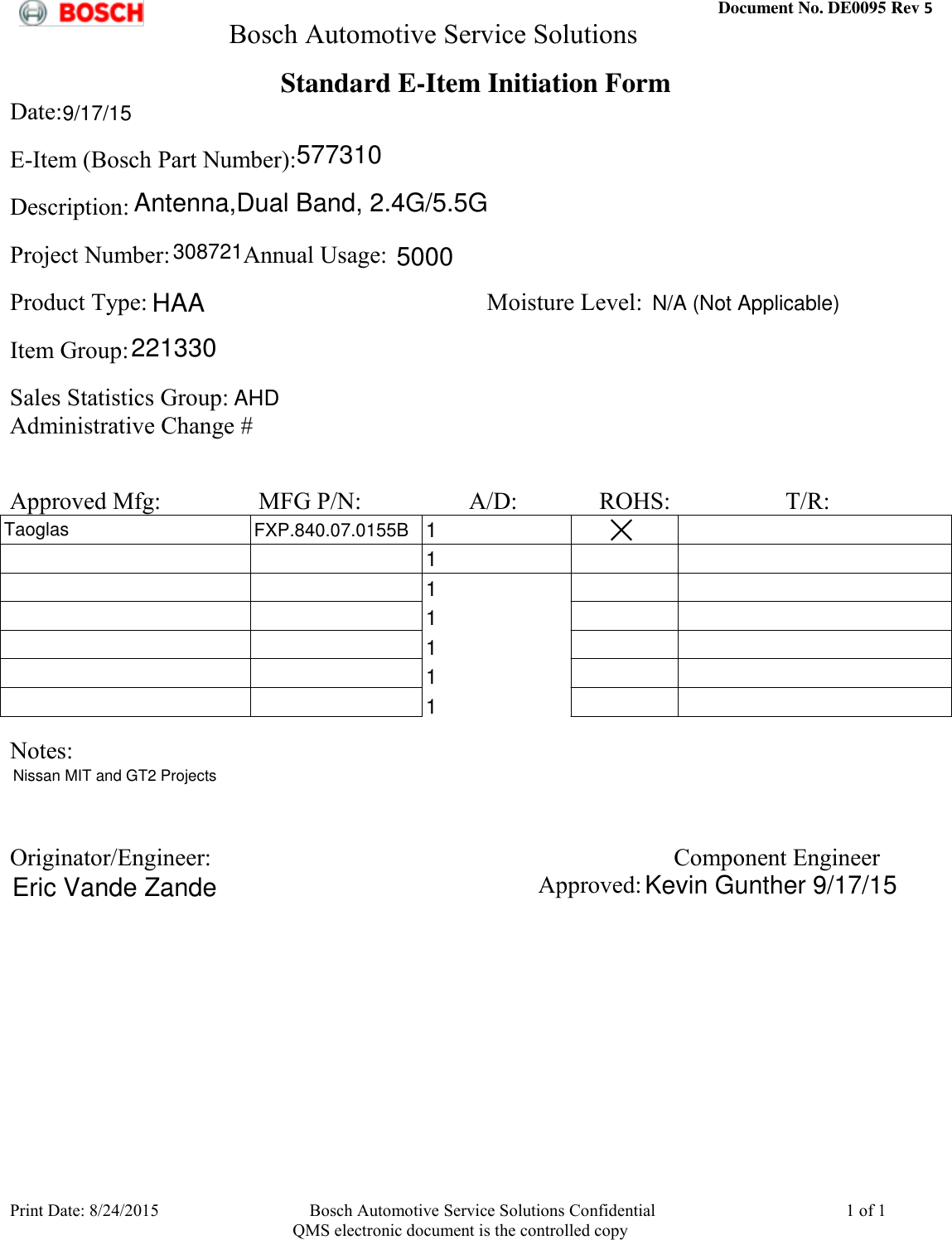
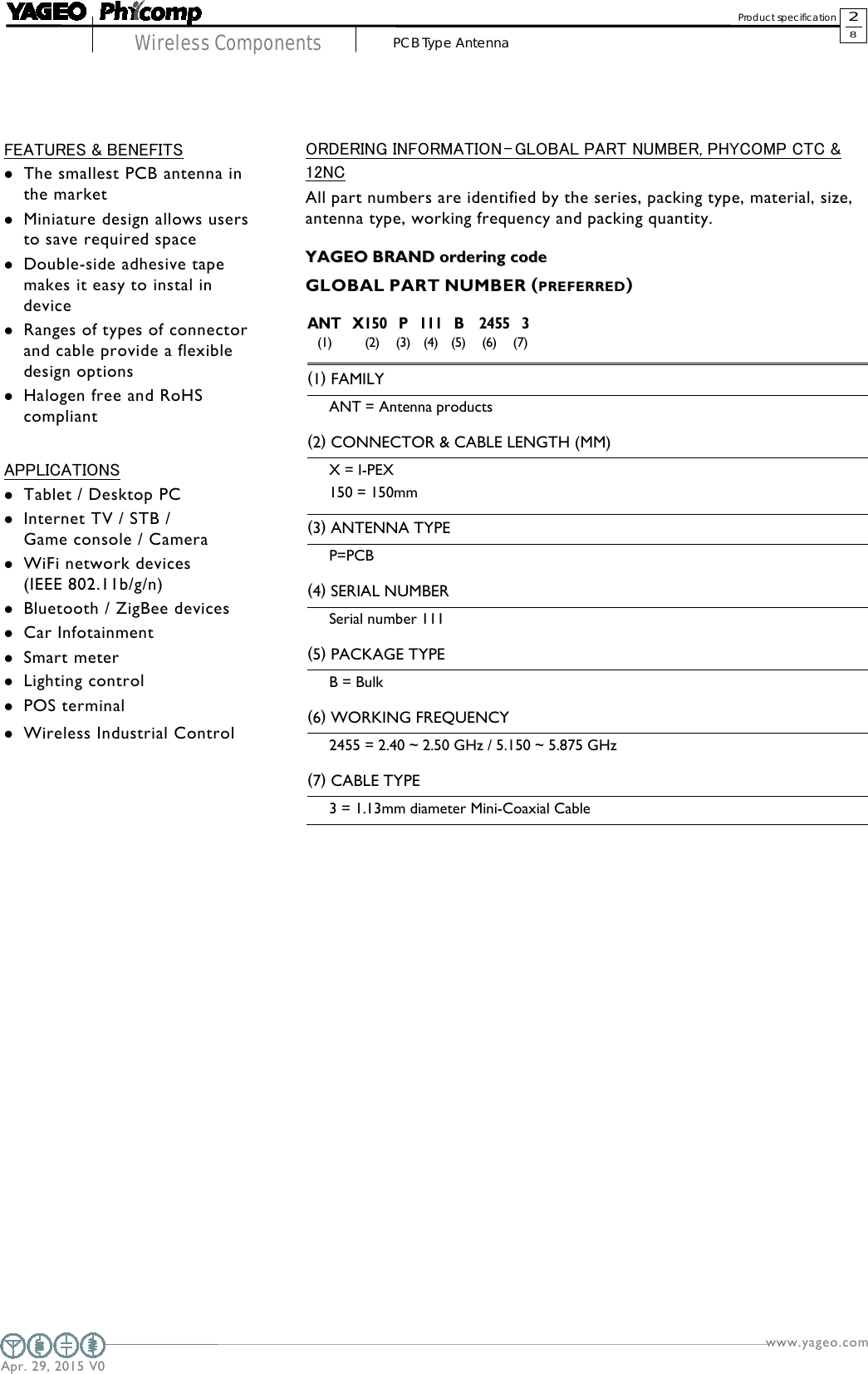
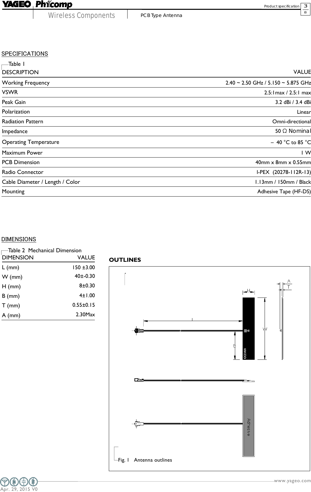
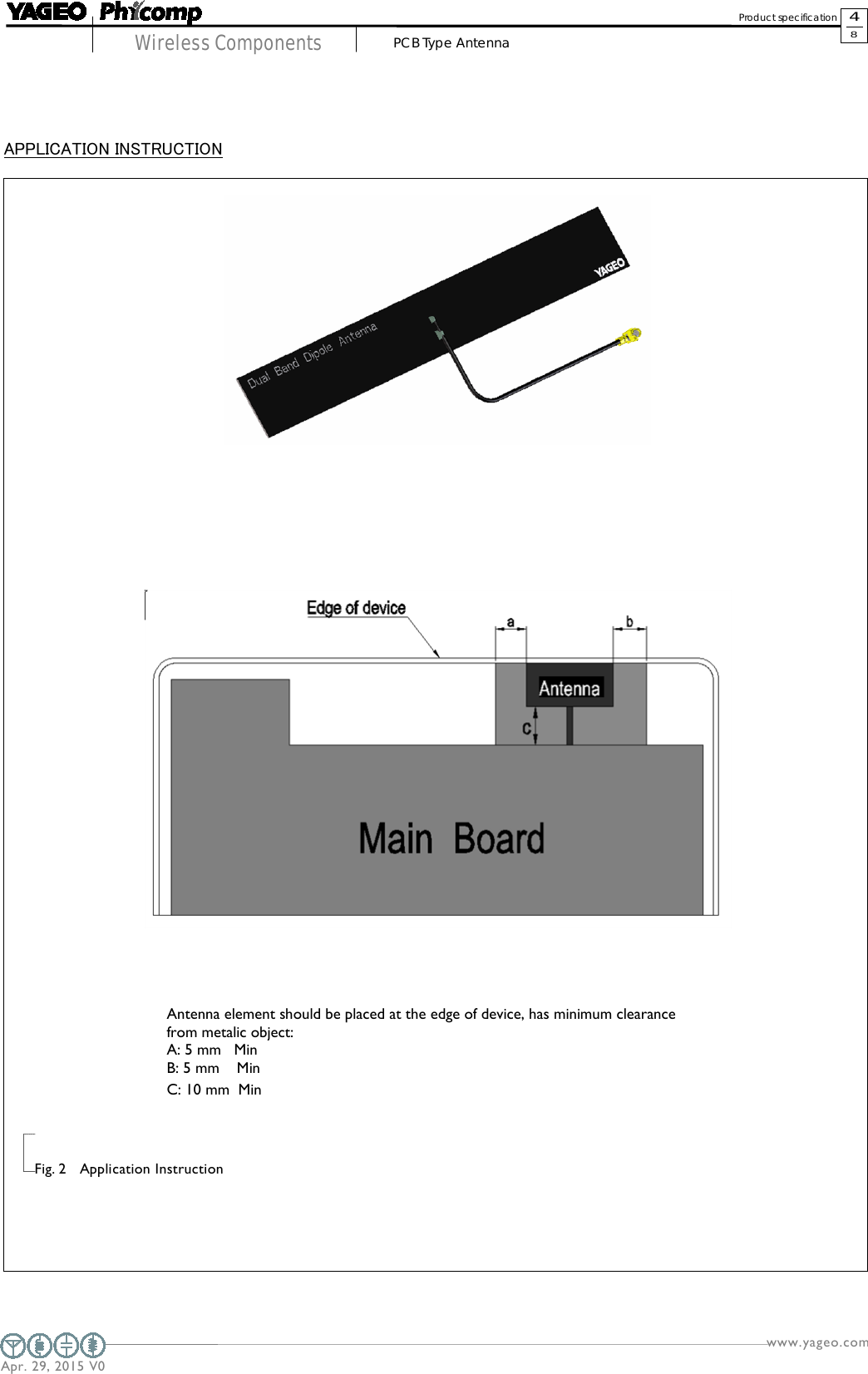
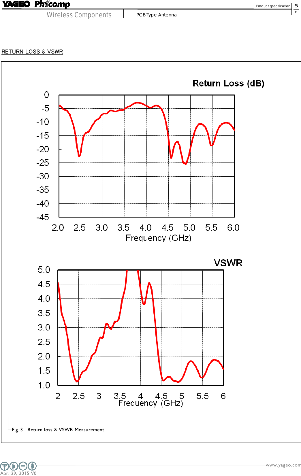
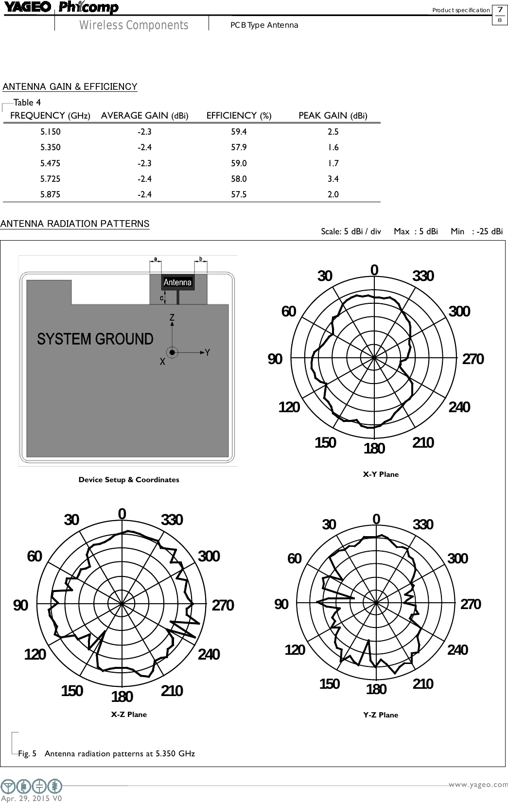
Antenna list for Module Integration and antenna spec