Bosch Automotive Service Solutions KT720 Automotive Diagnostics Equipment User Manual KT720 EN part 1

Bosch Automotive Service Solutions (Suzhou) Co., Ltd Shenzhen Branch Automotive Diagnostics Equipment KT720 EN part 1

Contents

KT720 EN User Manual -part 1
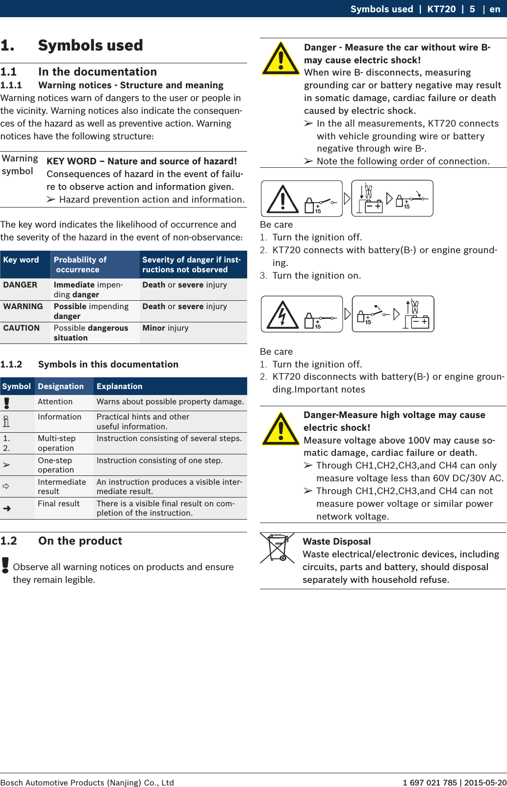
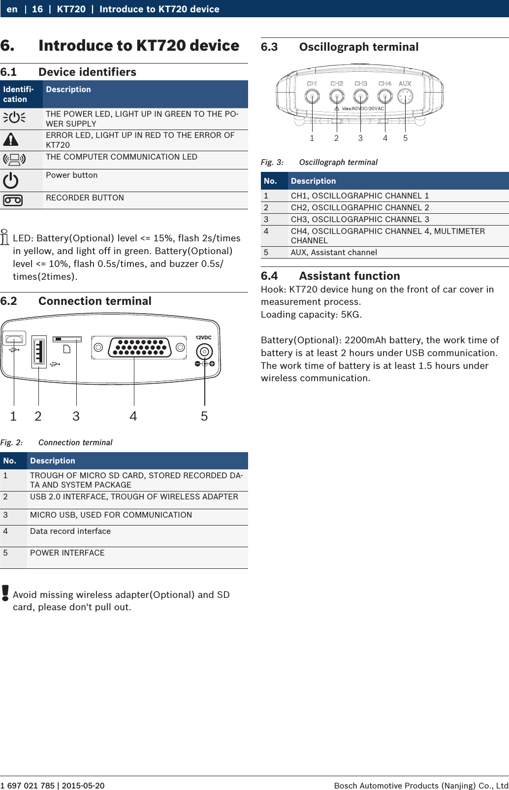
KT720enUser manual
1 697 021 785 | 2015-05-20Bosch Automotive Products (Nanjing) Co., Ltd    |  KT720  |  3 en1.  Symbols used  51.1  In the documentation  51.1.1  Warning notices - Structure and meaning  51.1.2  Symbols in this documentation  51.2  On the product  52.  Important Notice  62.1  User group  62.2 Agreement  62.3  Obligation of contractor  73.  Safety instructions  83.1  Risk of electric shocks  83.1.1  Low voltages, high voltages  83.1.2  High voltages in hybrid vehicles and elec-tric vehicles as well as their high-voltage components 83.2  Danger of acid burning  93.3  Danger of injury, Danger of crushing  93.4  Danger of burning  103.5  Danger of fire, Danger of explosion  103.6  Danger of asphyxiation  103.7  Danger of tripping  103.8 Noise  103.9  WLAN (Wireless Local Area Network)  113.9.1  Important information on WLAN  113.9.2  Information on access points  113.10  FCC Statement  123.11  Satety Warning  123.12  Using notes  133.13  Notes for operation of automobile ECU  134.  PC software environment  144.1  Computer parameters  144.2  Software installation guidance  144.3  USB driver installation  144.4  Software uninstall   155.  Packing list  156.  Introduce to KT720 device  166.1  Device identifiers  166.2  Connection terminal  166.3  Oscillograph terminal  166.4  Assistant function  167.  Equipment connection  177.1  Measured connection  177.2  Selfcheck / Upgrade connection  178.  Original start  179.  System setting  189.1  System setting  189.1.1  Language setting  189.1.2  User information  189.1.3  Password change  189.2  Software upgrading  189.2.1  Software online upgrade  189.2.2  Firmware upgrade  199.3  Communication setting  199.3.1  USB Communication Setting  199.3.2  Wireless communication settings  199.3.3  Wireless router communication settings 199.4 device  209.4.1  Product activation  209.4.2  Product information  209.4.3  Device information  209.4.4  Device Self-check  209.4.5  Battery information  2010.  vehicle diagnosis  2110.1  test condition  2110.2  Power supply  2110.3  Manual Selection  2110.4 Diagnostic  2110.4.1  Introduction to Main Interface of Diagno-sis System  2110.4.2  Reading Version Information  2210.4.3  Reading DTC  2210.4.4  Clearing DTC  2310.4.5  Reading Data Stream  2310.4.6  Playing Back Data Stream  2410.4.7  Action Test  2510.4.8  Advanced Functions  2510.5  Other Functions Related to Diagnostic  2510.5.1 Print  2510.5.2  Image Browse  26Contents
1 697 021 785 | 2015-05-20 Bosch Automotive Products (Nanjing) Co., Ltd 4  |  KT720  |  en11.  Measure function  2611.1  Power supply  2611.2  Function button introduce  2711.3  Parameters adjust  2711.3.1 Cycle  2711.3.2  Channels, amplitude and coupling  2711.3.3  Trigger function  2711.3.4 Reversed-phase  2811.3.5  Adjust cursor  2811.3.6  Waveform position  2811.3.7  Current clamp  2811.4  General oscilloscope  2811.4.1  Equipment connection  2811.4.2  Measuring conditions  2811.4.3  Measuring steps  2811.5 Recorder  2911.5.1  Equipment connection  2911.5.2  Measuring conditions  2911.5.3  Measuring steps  2911.6  Sensor measure  2911.6.1  Manifold absolute pressure sensor (MAP) 2911.6.2  Oxygen sensor-zirconium and titanium type 3111.6.3  Double oxygen sensor  3111.6.4  Temperature sensor  3211.6.5  Throttle position sensor  3311.6.6  Crankshaft/Camshaft position sensor  3511.6.7  Ride height (position) sensor  3611.6.8  Anti-lock braking speed sensor  3711.6.9  Vehicle speed sensor (VSS)  3811.6.10 Air flow sensor  3911.6.11 Knock sensor-piezoelectric crystal  4011.7  Actuator measure  4111.7.1  Exhaust gas recirculation  4111.7.2  Fuel Injection(FI)  4211.7.3  Coil and diode test  4411.7.4  Idle air/speed control (IAC/ISC)  4511.7.5  Distributor trigger  4611.7.6  Advance time  4711.8  Ignition system  4811.8.1  Secondary ignition  4811.8.2  Primary ignition  5011.9  Electrical system  5111.9.1  Battery test  5111.9.2  Charge test  5111.9.3  Current waveform  5211.10  Communication system  5311.10.1 High-speed CAN communication  5311.10.2 Low-speed CAN communication  5311.10.3 K-line  communication  5411.11 Multimeter  5411.11.1 DC  voltage  5411.11.2 AC voltage  5511.11.3 Switch  5511.11.4 Resistance  5611.11.5 Diode  test  5611.12  Record and playback functions  5612.  Auxiliary Function  5712.1  Screen shot  5712.2   Help  5712.3 Feedbacks  5713.  Maintenance Help  5714.  Service and maintenance  5714.1 Cleaning  5714.2 Maintenance  5814.3  Battery maintenance  5815. WARRANTY  5816.  Device parameters  5816.1  Device parameters  5816.2  Oscillograph parameters  5916.3  Multimeter parameters  59
1 697 021 785 | 2015-05-20Bosch Automotive Products (Nanjing) Co., Ltd Symbols used  |  KT720  |  5 en1.  Symbols used1.1  In the documentation1.1.1  Warning notices - Structure and meaningWarning notices warn of dangers to the user or people in the vicinity. Warning notices also indicate the consequen-ces of the hazard as well as preventive action. Warning notices have the following structure:Warning symbolKEY WORD – Nature and source of hazard!Consequences of hazard in the event of failu-re to observe action and information given. ¶Hazard prevention action and information.The key word indicates the likelihood of occurrence and the severity of the hazard in the event of non-observance:Key word Probability of  occurrenceSeverity of danger if inst-ructions not observedDANGER Immediate impen-ding dangerDeath or severe injuryWARNING Possible impending dangerDeath or severe injuryCAUTION Possible dangerous  situationMinor injury1.1.2  Symbols in this documentationSymbol Designation Explanation!Attention Warns about possible property damage.iInformation Practical hints and other  useful information.1.2.Multi-step  operationInstruction consisting of several steps.eOne-step  operationInstruction consisting of one step.Intermediate resultAn instruction produces a visible inter-mediate result."Final result There is a visible final result on com-pletion of the instruction.1.2  On the product !Observe all warning notices on products and ensure they remain legible.Danger - Measure the car without wire B- may cause electric shock!When wire B- disconnects, measuring grounding car or battery negative may result in somatic damage, cardiac failure or death caused by electric shock. ¶In the all measurements, KT720 connects with vehicle grounding wire or battery negative through wire B-. ¶Note the following order of connection.Be care1.  Turn the ignition off.2.  KT720 connects with battery(B-) or engine ground-ing.3.  Turn the ignition on.Be care1.  Turn the ignition off.2.  KT720 disconnects with battery(B-) or engine groun-ding.Important notesDanger-Measure high voltage may cause electric shock!Measure voltage above 100V may cause so-matic damage, cardiac failure or death. ¶Through CH1,CH2,CH3,and CH4 can only measure voltage less than 60V DC/30V AC. ¶Through CH1,CH2,CH3,and CH4 can not measure power voltage or similar power network voltage.Waste DisposalWaste electrical/electronic devices, including circuits, parts and battery, should disposal separately with household refuse.
1 697 021 785 | 2015-05-20 Bosch Automotive Products (Nanjing) Co., Ltd 6  |  KT720  |  Important Noticeen2.2  AgreementBy using the product you agree to the following regulations:Declare RRefer to packing list for detailed product configura-tion; RRefer to software for functions, pictures.This product cannot use in:Locations characterized by a separate power network, in most cases supplied from a high- or medium-voltage transformer, dedicated for the supply of installations feeding manufacturing or similar plants with one or more of the following conditions:– frequent switching of heavy inductive or capacitive loads;– high currents and associated magnetic fields;– presence of Industrial, Scientific and Medical (ISM) apparatus (for example, welding machines).The equipment complies with relevant requirements of Directive 2004/108/EC for Electromagnetic compatibili-ty (EMC) and Directive 2006/95/EC for Low Voltage. iCE only for KT720 deviceCopyrightSoftware and data are the property of Bosch or its suppliers and protected against copying by copyright laws, international agreements and other national legal regulations. Copying or selling of data and software or any part thereof is impermissible and punishable; in the event of any infringements Bosch reserves the right to proceed with criminal prosecution and to claim for damages.Liability2.1  User groupThe product may be used by skilled and instructed per-sonnel only. Personnel scheduled to be trained, famili-arized, instructed or to take part in a general training course may only work with the product under the su-pervision of an experienced person.All work conducted on electrical and hydraulic de-vices may be performed by persons with sufficient knowledge and experience in the field of electrics and hydraulics.Children have to be supervised to ensure that they do not play with the appliance.2.  Important Notice    Before start up, connecting and operating Bosch products it is absolutely essential that the operating instructions/owner’s manual and, in particular, the safety instructions are studied carefully. By doing so you can eliminate any uncertainties in handling Bosch products and thus associated safety risks upfront; something which is in the interests of your own safety and will ultimately help avoid damage to the device. When a Bosch product is handed over to another person, not only the operating instructions but also the safety instructions and information on its designated use must be handed over to the person.
1 697 021 785 | 2015-05-20Bosch Automotive Products (Nanjing) Co., Ltd Important Notice  |  KT720  |  7 enAll data in this program is based - where possible - on manufacturer and importer details. Bosch does not ac-cept liability for the correctness and completeness of software and data; liability for damage caused by faulty software and data is ruled out. Whatever the event, Bosch liability is restricted to the amount for which the customer actually pays for this product. This disclaimer of liability does not apply to damages caused by intent or gross negligence on the part of Bosch.WarrantyAny use of non-approved hardware and software will result in a modification to our product and thus to exclu-sion of any liability and warranty, even if the hardware or software has in the meantime been removed or deleted.No changes may be made to our products. Our products may only be used in combination with original acces-sories and original service parts. Failing to do so, will render null and void all warranty claims.This product may only be operated using Bosch appro-ved operating systems. If the product is operated using an operating system other than the approved one, then our warranty obligation pursuant to our supply condi-tions will be rendered null and void. Furthermore, we will not be held liable for damage and consequential damage incurred through the use of a non-approved operating system.2.3  Obligation of contractorThe contractor is obliged to ensure that all measures geared towards the prevention of accidents, industrial diseases, labor-related health risks are taken and mea-sures towards making the workplace fit for people to work in are carried out. Specifications for electrical systems (BGV A3)Electrical engineering in Germany is subject to the ac-cident prevention regulations of the trade association "Electrical Plant and Equipment as under BGV A3 (previ-ously VBG 4)". In all other countries, the applicable nati-onal regulations acts or decrees are to be adhered to.Basic rulesThe contractor is bound to ensure that all electrical equipment and operating material is set up, modified and maintained by skilled electricians only or under the guidance and supervision of a skilled electrician in accordance with electrical engineering principles. Furthermore, the contractor must ensure that all elec-trical equipment and operating material is operated in keeping with electrical engineering principles.If a piece of electrical equipment or operating material is found to be defective, i.e. it does not or no longer complies with electrical engineering principles, the con-tractor must ensure that the fault is rectified immedia-tely and, in the event that imminent danger exists, also ensure that the electrical equipment or the electrical operating material is not used.Tests (taking Germany as an example): RThe contractor must ensure that all electrical sys-tems and equipment are tested by a qualified electri-cian or under the guidance of a qualified electrician to ensure they are in proper working order: $Before starting for the first time.  $After modification or repair before starting for the first time.  $At given intervals. Set intervals such as to ensu-re that faults that can be expected to occur are determined in good time. RThe test is to take the electrical engineering princip-les relating hereto into account. RUpon request of the trade association, a test manual is to be maintained into which specific entries are made.
1 697 021 785 | 2015-05-20 Bosch Automotive Products (Nanjing) Co., Ltd 8  |  KT720  |  Safety instructionsen3.  Safety instructions3.1  Risk of electric shocks3.1.1  Low voltages, high voltagesHazardous voltages occur in both the lighting system and the electrical system of a motor vehicle. If contact is made with live parts (e.g. with the ignition coil), there is a risk of electric shock from flashover voltages caused by damaged insulation (e.g. ignition cables which have been attacked by martens). These apply to the secondary and primary sides of the ignition system, the wiring harness with connectors, lighting system (Litronic) as well as connection to the vehicle.Safety measures: ¶Only connect to a properly grounded outlet. ¶Only the enclosed or a tested power supply cable is to be used. ¶All extension cables must be fitted with shock-proof contacts. ¶Any cables with damaged insulation must be repla-ced. ¶First connect the lighting system and turn it on befo-re connecting it to the vehicle. ¶Before switching on the ignition connect the (B-) cable to engine ground or the battery (B–) terminal. ¶Always switch off the ignition before performing any work on the electrical system of the vehicle. Inter-vention includes, for instance, connection to the vehicle, replacement of ignition system components, removal of equipment (e. g. alternators), connection of equipment to a test bench. ¶Wherever possible, tests and settings should always be caried out with the ignition switched off and the engine stationary. ¶If tests or settings are carried out with the ignition switched on or the engine running, care must be taken not to touch any live parts. This applies to all connection cables and leads as well as to connec-tions of equipment to test benches. ¶Test connections must always be made using sui-table connectors (e.g. Bosch testing cable set or vehicle-specific adapter cables). ¶Make sure that all test connections are properly plugged in and secure. ¶Before disconnecting the (B-) cable from the engine ground or battery (B–), switch off the ignition. ¶Never open the enclosures.3.1.2  High voltages in hybrid vehicles and electric ve-hicles as well as their high-voltage componentsIf high-voltage components or high-voltage wires are inexpertly handled, there is a risk of fatal injury from high voltages and the possib-le transmission of current through the body.  ¶Deenergization is only to be performed by a qualified electrician, a qualified electri-cian for specific tasks (hybrid) or a power systems engineer.   ¶Work on vehicles with high-voltage compo-nents is only ever to be performed in a safe, deenergized condition by persons with the minimum qualification "Trained to perform electrical work".  ¶Even after deactivating the high-voltage vehicle electrical system, the high-voltage battery may still be live. ¶Operating condition cannot be established from any running noise, as the electric ma-chine is silent when stationary. ¶In gear positions "P" and "N" the engine or electric motor may start spontaneously depen-ding on the charge of the high-voltage battery.Safety measures: ¶Never open or damage high-voltage batteries. ¶On accident vehicles, never touch high-voltage com-ponents or exposed high-voltage wires before deacti-vating the high-voltage vehicle electrical system. ¶Avoid contact with any high-voltage components and high-voltage wires (orange sheathing) when in operation. ¶Secure against unauthorized renewed start-up  (e.g. by means of a padlock). ¶Always wait at least 10 seconds after deactivating the high-voltage system. ¶Visually inspect the high-voltage components and high-voltage wires for damage. The power systems engineer responsible should always be immediate-ly notified of any irregularities, doubts or defects found. $High-voltage components must never exhibit signs of external damage. $The insulation of the high-voltage wiring must be intact and undamaged. $Watch out for any abnormal deformation of the high-voltage wiring.
1 697 021 785 | 2015-05-20Bosch Automotive Products (Nanjing) Co., Ltd Safety instructions  |  KT720  |  9 en3.2  Danger of acid burningWhen exhaust gas measurements are taken, the sampling hoses which are used release a highly caustic gas (hydrogen fluoride) that can cause acid burning in the respiratory system when heated to temperatures in excess of  250 °C (482 °F) or in the event of fire.Rules of conduct: ¶Consult a doctor immediately after inhaling! ¶Always wear gloves made of neoprene or PVC when removing residues left after a fire. ¶Neutralize any residues left after a fire with a cal-cium hydroxide solution. This produces non-toxic calcium fluoride, which can be washed away.Acids and alkalis can cause severe burning on unprotected skin. Hydrogen fluoride in combi-nation with moisture (water) forms hydroflu-oric acid. The condensate, which accumulates in the sampling hose and in the condensate container likewise contains acid.Rules of conduct: ¶When replacing the O2 measuring sensor, bear in mind that it contains alkali. ¶When replacing the NO measuring sensor, bear in mind that it contains acid. ¶Rinse any affected parts of the skin immediately in water, then consult a doctor! ¶NO and O2 measuring sensors are hazardous waste and must be disposed of separately. Your Bosch spe-cialist equipper can dispose of sensors in the proper manner.If fluid (electrolyte) escapes from batteries and rechargeable batteries, avoid getting it on your skin or in your eyes.Rules of conduct: ¶If contact with skin or eyes happens nevertheless, wash the affected parts immediately with clean wa-ter and then consult a doctor.3.3  Danger of injury, Danger of crushingThe vehicle has rotating and moving parts that can injure fingers and arms.If the vehicle is not prevented from rolling away, there is a danger of people being crus-hed against a workbench, for example.There is the risk with electrically operated fans in particular that the fan can start run-ning unexpectedly even when the engine and ignition are off.Safety measures: ¶Take steps to prevent the vehicle from rolling away while it is being tested. Select the park position if the vehicle has an automatic transmission and apply the handbrake or lock the wheels with chocks (wedges). ¶Operating staff must wear work clothes without loose bands and loops. ¶Do not reach in any area with rotating or moving parts. ¶When working on or in the vicinity of electrically driven fans, allow the engine to cool down first, then disconnect the plug of the fan motor. ¶Route cables at a suitable distance from rotating parts. ¶Secure the trolley against rolling away by setting the brakes. ¶Do not place heavy objects on or lean on the sensor holder. ¶Transport and operate the equipment only in ac-cordance with the operating instructions.
1 697 021 785 | 2015-05-20 Bosch Automotive Products (Nanjing) Co., Ltd 10  |  KT720  |  Safety instructionsen3.4  Danger of burningWhen working on a hot engine, there is a risk of injury from burning if such components as the exhaust gas manifold, the turbo-charger, the Lambda sensor, etc. are touched or if parts of the body come too close to them. These components may be heated to tempe-ratures of several hundred degrees Celsius. Depending on the duration of the exhaust gas measurements, the sampling probe of the exhaust gas measuring instrument may also become extremely hot.Safety measures: ¶Always wear protective clothing, e.g. gloves. ¶Allow the engine to cool down first. This also applies to auxiliary heating systems. ¶Keep connecting cables well away from all hot parts. ¶Do not leave the engine running any longer than necessary for the test or setting.3.5  Danger of fire, Danger of explosionThere is a risk of fire and explosion from fuels and fuel vapors when work is performed on the fuel system or on the mixture control system.Safety measures: ¶Switch off the ignition. ¶Allow the engine to cool down first. ¶Avoid naked flames and potential sources of sparks. ¶Do not smoke. ¶Collect any leaked fuel. ¶Always ensure effective ventilation and suction when working in closed areas.3.6  Danger of asphyxiationCar exhaust fumes contain carbon monoxide (CO) - a colorless, odorless gas. If inhaled, carbon monoxide causes an oxygen deficien-cy in the body. Extreme caution is therefore essential when working in a pit, as some of the components of the exhaust gas are heavier than air and settle at the bottom of the pit. Caution is also necessary when working on LPG-driven vehicles.Safety measures: ¶Always ensure effective ventilation and suction (es-pecially when working in a pit). ¶Always switch on and connect the suction plant in a closed area.3.7  Danger of trippingWhen conducting tests or making adjust-ments, the sensor and connection cables increase the risk of tripping.Safety measures: ¶Route the connecting cables such that any risk of tripping up is prevented.3.8  NoiseNoise levels in excess of 70 dB(A) can oc-cur when measurements are carried out on a vehicle, especially at high engine speeds. Damage to hearing may result if human beings are exposed to noise at such levels over an extended period of time.Safety measures: ¶Noise protection facilities must be provided by the ow-ner at all workplaces in the vicinity of the testing area. ¶Suitable personal noise protection facilities must be used by the operator.
1 697 021 785 | 2015-05-20Bosch Automotive Products (Nanjing) Co., Ltd Safety instructions  |  KT720  |  11 en RHave your network infrastructure installed and tes-ted in advance by a data systems expert. RKeep the SSID and the codes for the radio link in a safe place. Make sure these data are readily to hand in case faults occur. RWe recommend a thorough inspection of the pre-mises on commissioning: Establish where in the buil-ding the VCI works properly and where the operating limits are. RIf the VCI is to be used in a vehicle, radio communi-cation can be severely limited. RThe radio link is affected by weather conditions. The reception signal may therefore vary.  RPlease contact your network administrator with any queries.3.9.2  Information on access pointsA wireless access point is an electronic device, which acts as an interface between a radio network and a cable-connected computer network. It provides a wi-reless connection between the KTS 340, the PC/laptop with ESI[tronic] Startcenter and a printer, for example. iWe recommend using WLAN standard IEEE 802.11b (data transmission rate max. 11 Mbps) for the access point. The "extended range" function is not supported. Please note the following: RThe access point should be located as centrally and high up as possible, ideally under the ceiling. RThe access point antenna should face downwards towards the floor.  RIn the event of a poor connection it may be useful to change the set channel on the access point. If pos-sible, avoid using neighboring channels to channels that are already in use.3.9  WLAN (Wireless Local Area Network)KT720 does not have wifi capabilities, the need for ad-ditional access a certified USB wifi module to achieve this function.3.9.1  Important information on WLANWLAN stands for Wireless Local Area Network. As with Bluetooth, WLAN provides a radio link on the free 2.4 GHz ISM band (ISM: Industrial, Scientific, Medical). This frequency range is subject to government regula-tions, but may be used without a license in most coun-tries. Consequently a large number of applications and devices employ this frequency band for transmission. This can result in frequency interference.Depending on ambient conditions, the WLAN link may therefore deteriorate, e.g. in the case of Bluetooth links, cordless telephones, radio-controlled thermometers, radio-controlled garage door openers, radio-controlled light switches or radio-controlled alarm systems. iBluetooth can lead to interference in the bandwidth of the WLAN network. The antennas of Bluetooth and WLAN devices should be at least 30 centime-ters apart. Do not plug Bluetooth USB adapters and WLAN sticks into adjacent USB slots on PCs/laptops. Use the USB extension cable (special accessory) to maintain a distance between the Bluetooth USB adapter and the WLAN stick on the PC/laptop. iExercise extreme caution if wearing pacemakers or other vital electronic devices when using radio systems, as proper functioning of these items could be impaired.Note the following to ensure the best possible connec-tivity: RThe WLAN radio signal always tries to find the most direct path. When setting up the PC/laptop and access point (see section 2.6.2), make sure there are as few obstacles as possible (e.g. steel doors and concrete walls), which could interfere with the radio signal from and to the KTS 340. Inside buildings, the range of the WLAN is also greatly influenced by the construction materials used. Conventional masonry, wooden walls and certain types of dry construction wall scarcely impede radio waves. Thin gypsum walls can however cause problems, as considerable amounts of moisture may accumulate in the gypsum and result in the absorption of radio signals. Con-crete (and in particular reinforced concrete) largely blocks out radio waves. Cellar ceilings are often impenetrable. Generally speaking, walls with a lot of installed metal (e.g. pipes, wires) obstruct radio waves.  RRadio reception is also impeded by large metal ob-jects such as radiators and window frames as well as active sources of interference such as DECT telepho-nes and microwave ovens.
1 697 021 785 | 2015-05-20 Bosch Automotive Products (Nanjing) Co., Ltd 12  |  KT720  |  Safety instructionsen RWe recommend that encryption of radio communica-tions is configured at the access point.3.10  FCC StatementThis equipment has been tested and found to comply with the limits for a Class B digital device, pursuant to part 15 of the FCC rules. These limits are designed to provide reasonable protection against harmful in-terference in a residential installation. This equipment generates, uses, and can radiate radio frequency energy and, if not installed and used in accordance with the instructions,may cause harmful interference to radio communications. However, there is no guarantee that interference will not occur in a particular installation.If this equipment does cause harmful interference to radio or television reception, which can be determined by turning the equipment off and on, the user is encou-raged to try to correct the interference by one or more of the following measures: RReorient or relocate the receiving antenna. RIncrease the separation between the equipment and receiver. RConnect the equipment into an outlet on a circuit different from that to which the receiver is connec-ted. RConsult the dealer or an experienced radio/TV tech-nician for help.To assure continued compliance, any changes or modi-fications not expressly approved by the party respon-sible for compliance could void the user’s authority to operate this equipment.MODIFICATIONAny changes or modifications not expressly approved by the grantee of this device could void the user’s authori-ty to operate the device.3.11  Satety Warning RInspection shall be carried out in good ventilation. Connect the exhaust pipe to outside if there is no enough ventilation; RSmoking and open fire are prohibited in the inspec-tion; RThe battery liquid contains sulphuric acid that could erode the skin. Avoid battery liquid from touching the skin directly in operation, especially note that the liquid shall not be splashed into eye; RThe engine temperature is high when running. Avoid touching the high-temperature parts, such as radia-tor and exhaust pipe; RPull manual brake before starting the engine. Block the front wheels and place shift lever at P or neutral gear to avoid accident when starting the engine; RIf external batter is used as power supply, pay attention to the electrode; use red alligator clip to connect anode and black alligator clip to connect cathode; RKeep all the power cables, pens and tools away from belt or other moving parts if using instrument in engine compartment; RDo not wear watch, ring and loose clothes in mainte-nance for engine compartment; RWear approved safety glasses in all inspection pro-cesses; ROnly the enclosed power adapter or power supply cable can be used for supply connection; RIf the equipment is used in a manner not specified by the manufacturer, the protection provided by the equipment may be impaired. RAny parts of the device and its accessories are not allowed to be changed or replaced, other than autho-rized by the manufacturer or his agent. RCheck the equipment is in good working condition before use by testing it in a known voltage supply. RBefore touching conductive parts, the absence of ha-zardous voltage must be checked with the two-pole direct contact measurement of other equipment. RNot to use the equipment for measurements on mains circuits, not to use the equipment for measu-
1 697 021 785 | 2015-05-20Bosch Automotive Products (Nanjing) Co., Ltd Safety instructions  |  KT720  |  13 enrements on voltage exceed the voltage range descri-be in the manual.3.12  Using notes RThe instrument is precise electronic instrument, do not drop it. RThe instrument may respond slowly in first inspec-tion. Please be patient. Do not operate the instru-ment frequently. REnsure that the instrument and the diagnosis retai-ner are connected securely, otherwise the interrup-ted signal will affect the test. If they can’t be con-nected normally, pull out the connector and plug it again. Do not shake the connector in using. RUse screw to fasten the connection wire and con-nectors to avoid disconnecting and damaging the interface. Hold the front end of the connector when pulling it. Do not pull the rear connection wire. RHandle the instrument gently and put it in safe place to avoid impact. Shut off the power when not using. Rafter using and put the accessories into the kit. ROnline upgrade will be affected by local wire speed. Please wait patiently if the loading is slow. RCertain inspection and maintenance basis are requi-red to operate the instrument, as well as electrical control system of the inspected automobile.3.13  Notes for operation of automobile ECUPay attention to the following when diagnosing the au-tomobile equipped with computer control system: RDo not put the magnetic objects, such as radio loudspeaker near the computer, because the magne-tism of the loudspeaker will damage the circuits and parts in ECU. RNever switch off the internal electrical devices when the ignition switch is on. The self-induction of the coil when power-off will generate high instantaneous voltage that will damage the sensor and ECU. RSpecial attention shall be paid to avoid damaging ECU and sensor when carrying out maintenance near the computer or sensor. RConnect the ECU harness connector securely, other-wise it will damage the electronic units, such as integral circuit in ECU. RWear earthing metal strap with one end on the body and another end twisting finesse when repairing or approaching ECU-control digital instrument. RShut down ECU system power before welding on the automobile. RUnless specified, do not test the electrical devices related to ECU with test lamp to avoid damaging ECU or sensor. RUnless specified in test process, use digital instru-ment with high impedance to test ECU and sensor, rather than pointer ohm gauge.
1 697 021 785 | 2015-05-20 Bosch Automotive Products (Nanjing) Co., Ltd 14  |  KT720  |  PC software environmenten4.  PC software environmentAs KT720 operates based on the computer, the KT720 software and relevant hardware driver software shall be installed onto the computer first of all.4.1  Computer parametersConfigu-rationParameter (Recommen-ded)Parameter (Minimum)Main fre-quency CPU larger than 2GHz CPU larger than 1.5GHzMemory Larger than 4GB Larger than 2GBFree space of  hard discLarger than 2GB Larger than 1GBUSB inter-faceUSB2.0 full speed or high speedUSB2.0 full speed or high speedWLAN Wireless network card(WPA/WPA2+PSK)Wireless network card(WPA/WPA2+PSK)Display re-solutionHigher than 1280*768, 32-bit above color depthOS WINDOWS XP /WIN-DOWS 7WINDOWS XP /WIN-DOWS 74.2  Software installation guidanceInstallation Steps:1.  Get the installation file(KT720 _Full_Setup_V2.5.7.exe) from the CD disc furnished by Bosch Au-tomotive Diagnostics Equipment (Shenzhen) Limited or its official website;2.  Double click the file;3.  Click the “Next” button to get the interface display-ing the user license protocol, which shall be carefully read; if you accept all protocols, please click the “Accept (I)” button;4.  Select the target folder for software installation (disc C is the default file location); you can click the “Browse” button to select the target folder, and the program will automatically detect the corresponding used and free spaces of target disc;5.  Click the “Installation” button, and the software will be under installation; please wait for the installation completion;6.  Installation for the first time, if KT720 connected to the computer properly, please refer to chapter 4.3 USB drive manual installation guide;7.  After installation, if you select the “Run KT720 ” and click the “Finish” button, the installation completion will be confirmed and the KT720 software will be run; if you only click the “Finish” button, the instal-lation completion will be confirmed but the KT720 software will not be run;8.  After installation, the shortcut will be displayed on the computer desktop; just click the shortcut to run the KT720 software. iNeed to manually install the USB driver software in-stallation is completed, please refer to 4.3 USB drive manual installation guide. iYou are adminiatrator when you insatll software;You have access to write installed folders; iPlease install the PDF reader to view more help files conveniently.4.3  USB driver installationyou must to manual install USB driver after KT720 soft-ware intallation.Installation steps:1.  Connected KT720 device and computer by USB cable.2.  Select "Device Manager" in "Control Panel";3.  Select "RNDIS/Ethernet Gadget" in "Other Device";4.  Click right mouse button, select "Update Driver Software ";5.  Select "Browse my computer for driver software";6.  Click "Browse" button, find the driver software in in-stall folder of BOSCH\KT720 \Driver\KT720 _Driver .7.  Click "Next" button, wait for install successfully.
1 697 021 785 | 2015-05-20Bosch Automotive Products (Nanjing) Co., Ltd Packing list  |  KT720  |  15 en4.4  Software uninstall After installing the software,KT720 folder will be dis-played under the program submenu of the “Start” menu.Directly click “Uninstall” to uninstall the software. Please operate following the interface prompts till the uninstall completion.5.  Packing listName Part.No AmountKT720 device 1697021769 1Quick Start for KT720  1697021770 1KT720 User Manual 1697021771 1KT720 carry case 1697021772 1KT diagnostic software CD 1697021784 1Power Adapter 1697021651 1Power calbe:Chinese 3 Pins Pow-er Supply1697501314 1USB Communication Cable 1697021648 1Diagnostic extension cabel 1697021637 1MITSUBISHI Adapter 12Pin 1697021640 1Multi-Function Adapter jumper wire 1697021639 1OBD 16Pin Adapter 1697021636 1Mazda 17Pin Adapter 1697021638 1Toyota 17Pin Adapter_Square 1697021644 1NISSAN  14Pin Adapter 1697021645 1Honda 3Pin Adapter 1697021646 1CHERY/GEELY 3PIN ADAPTER 1697021649 1MIN-CAR 3PIN ADAPER 1697021650 1Adapter for Hyundai Remote device 1697021643 1KIA Adapter_Red 1697021641 1KIA Adapter_Black 1697021642 1POWER EXTENSION CABLE 1697020105 1ALLIGATOR CLIP SUPPLY CABLE 1697020106 1CIGARETTE  IGNITER SUPPLY CABLE1697020107 1RED CAPACITIVE PICKUP 1697020114 1GREY CAPACITIVE PICKUP 1697020115 1RED BANANA SOCKET 1697020117 1GRAY BANANA SOCKET 1697020118 1BLACK BANANA SOCKET 1697020119 11 CYLINDER SIGNAL CLIP 1697020120 1BLACK ALLIGATOR CLIP 1697020125 1RED ALLIGATOR CLIP 1697020124 1DIFFERENTIAL PROBES 1697021743 1OSCILLOSCOPE PROBE 1697021745 3KT700 VMI BATTERY(Optional) 1697020132 1WIFI MODULE 1697021717 1MICRO SD CARD 1697021756 1PORTABLE COMPUTER 1
1 697 021 785 | 2015-05-20 Bosch Automotive Products (Nanjing) Co., Ltd 16  |  KT720  |  Introduce to KT720 deviceen6.  Introduce to KT720 device6.1  Device identifiersIdentifi-cationDescriptionTHE POWER LED, LIGHT UP IN GREEN TO THE PO-WER SUPPLYERROR LED, LIGHT UP IN RED TO THE ERROR OF KT720 THE COMPUTER COMMUNICATION LEDPower buttonRECORDER BUTTON iLED: Battery(Optional) level <= 15%, flash 2s/times in yellow, and light off in green. Battery(Optional) level <= 10%, flash 0.5s/times, and buzzer 0.5s/times(2times).6.2  Connection terminal12 34512VDCFig. 2:  Connection terminalNo. Description1 TROUGH OF MICRO SD CARD, STORED RECORDED DA-TA AND SYSTEM PACKAGE2 USB 2.0 INTERFACE, TROUGH OF WIRELESS ADAPTER3 MICRO USB, USED FOR COMMUNICATION4 Data record interface5 POWER INTERFACE !Avoid missing wireless adapter(Optional) and SD card, please don't pull out.6.3  Oscillograph terminal12345Fig. 3:  Oscillograph terminalNo. Description1 CH1, OSCILLOGRAPHIC CHANNEL 12 CH2, OSCILLOGRAPHIC CHANNEL 23 CH3, OSCILLOGRAPHIC CHANNEL 34 CH4, OSCILLOGRAPHIC CHANNEL 4, MULTIMETER CHANNEL5 AUX, Assistant channel6.4  Assistant functionHook: KT720 device hung on the front of car cover in measurement process.Loading capacity: 5KG.Battery(Optional): 2200mAh battery, the work time of battery is at least 2 hours under USB communication. The work time of battery is at least 1.5 hours under wireless communication.
1 697 021 785 | 2015-05-20Bosch Automotive Products (Nanjing) Co., Ltd Equipment connection  |  KT720  |  17 en7.  Equipment connectionAccording to different functions, the connection modes are: including measure connection, selfcheck connec-tion and upgrade connection.7.1  Measured connectionBefore using the equipment, please ensure the normal connection among the KT720 , computer, and measu-re assembly. The default measure is USB.Connection mode switch, please refer to section 9.3.12119138710X1     X2     X41415654321Fig. 4:  Measured connection1 oscilloscope probe2 Capacitive pickup(Red, Gray)3 1 cylinder signal4 differential probes5 Banana socket(Red, Gray, Black)6 Crocod clip(Red, Black)7 Cigarette igniter supply cable8 Battery terminal power supply line9 KT720 device10 Power extension cable11 USB communication cable12 Computer13 Diagnostic extension cable14 Diagnosis of car15 Connector iThe power supply when measured : Alligator clip supply calbe, Cigarette igniter supply cable, or Battery terminal power supply line, the diagnostic line of power supply (only in the diagnosis of mode) or battery machine (at the oscilloscope function is recommended to use the way of power supply) iThe measured cable: Capacitive pickup, 1 cylinder signal,oscilloscope probe or differential probes con-nected with banana socket and crocod clip.7.2  Selfcheck / Upgrade connection23451Fig. 5:  Selfcheck / Upgrade connection1 Power cable:chinese 3 pins power supply2 Power adapter3 KT720 device4 USB communication cable5 Computer iYou can connected computer and KT720 through wireless.8.  Original startThe default communication mode of KT720 is USB com-munication, and if KT720 device and computer are pro-perly connected through USB cable, the software will be automatically configure USB communication mode when you start KT720 software.You can use KT720 only after it is activated. Please refer to the steps in Section 9.4.1 to activate.To measure the vehicle with the latest software, firm-ware and system, please refer to Section 9.2 to upgrade the software, firmware and system.
1 697 021 785 | 2015-05-20 Bosch Automotive Products (Nanjing) Co., Ltd 18  |  KT720  |  System settingen9.  System settingKT720 settings include system setting, software up-grade, communication setting andKT720 theses four functions.9.1  System settingSystem setting includes language setting, user informa-tion, proxy setting and password change.9.1.1  Language settingKT720 provides various language systems available for users to switch languages. Operation steps:1.  Select "system Settings" module under the "langua-ge";2.  Enter the language setting module, and select re-quired language in the check box of “please select languages”;3.  Click “OK” button, and the interface will prompt “Ac-tivation takes effect when you reboot the system!”4.  Restart KT720 software.9.1.2  User informationUser information includes contact person, contact num-ber, name, code and address of workshop and notes.Operation steps:1.  Select "system Settings" module under the "user information";2.  Input your information in all input boxes marked with “*”.3.  Click “OK” button to save the user information you input, and click “Cancel” button to cancel the user information you input”. iUser information is the same as the information to be input when printing, and no more input is requi-red after the user information is saved.9.1.3  Password changeThis function can be used only after it is activated.Operation steps:1.  Select "system Settings" module under the "pass-word change";2.  If KT720 is properly connected with the computer, the serial number of the product will be automati-cally acquired.3.  Input correct user name and original password in proper order.4.  Input new password and confirmed password again, and new password must be exactly consistent with confirmed password, otherwise the password can’t be modified.9.2  Software upgradingSoftware upgrading includes software online upgrade,firmware upgrade.The function can be used only after the product is acti-vated. If not, the interface will display “Not Activated”. iPlease confirm whether your KT720 is properly con-nected with the computer through USB cable before upgrade,See 9.3.1 connection method. iPlease ensure the process integrity, and do not forcefully stop the program.9.2.1  Software online upgradeKT720 application software is Diagnosis database and system upgraded on line.Operation steps:1.  Select "software upgrade" module under "software upgrade" online;2.  The software will automatically check the current version of application software installed on your computer.3.  Please click “Check new version” button, and the system will automatically login and check the latest version by saved user name and password, and display in “Latest version” column; if the user name and password are incorrect, the system will enter the user login interface, please recheck the latest version after inputting user name and password.4.  If a latest version is detected, the interface will dis-play “Download” button.5.  Please click “Download” button, wait, and monitor the download progress by downloading progress bar.
1 697 021 785 | 2015-05-20Bosch Automotive Products (Nanjing) Co., Ltd System setting  |  KT720  |  19 en6.  Please click “Install” button after download, and install the upgrade package following the on screen prompts.7.  The application software of the latest version can be used only after restarting software.8.  If the user name and password are incorrect, you will be prompted, that the incorrect input shall not exceed 3 times. If so, you can re-input after 15 minutes.9.2.2  Firmware upgradeKT720 after the software upgrade, the system will au-tomatically detect the firmware version, if you have a new firmware version, interface will automatically pop up the firmware update interface, prompted to upgrade the new solid pieces.Operation steps:1.  KT720 connected to the computer with USB cable,connection methods see 9.3.1;2.  System automatically detects the current version of the software on your computer and automatically upgrade.9.3  Communication settingKT720 communication settings include: USB, wireless and wireless router communication.9.3.1  USB Communication SettingThe default communication mode of KT720 is USB com-munication.After other communication modes are successfully ap-plied, switch to USB communication mode, please set up following the below methods.Operation steps:1.  Connect the KT720 to the computer with USB cable The interface will pop out a prompt dialog box.2.  Click “Yes” button and wait till the automatic con-nection is successful.9.3.2  Wireless communication settingsOperation steps:1.  Enter “Communication Setting” model after USB module is communicated successfully;2.   select “Wireless Mode” from “Connection Type” till the automatic connection is successful;3.  Disconnect the USB cable after successful connec-tion. iIP address in the wireless connection property of the computer must be automatically acquired.9.3.3  Wireless router communication settingsOperation steps:1.  Enter “Communication Setting” after USB model is communicated successfully, and click “Wireless Network Connection” button to view all available wireless router networks.2.  Select wireless network, and double click its name to connect. iIf the wireless router network is protected by pass-word, you must input correct password to connect after double clicking the name.3.  Select “Wireless Router Mode” from “Connect type” after successful wireless connection till the automa-tic connection is successful.4.  Disconnect the USB cable after successful connec-tion. iPlease set the Security Mode of wireless router as WPA- Personal or WPA2-Personal. iIf there is a router isolation (AP Isolation or Wireless Isolation) function option, please disable the func-tion. iIt is suggested to close the firewall of router.
1 697 021 785 | 2015-05-20 Bosch Automotive Products (Nanjing) Co., Ltd 20  |  KT720  |  System settingen9.4.2  Product informationProduct information includes product’s serial number, equipment type, model, software version and activation status. The system will automatically check the product information after KT720 is properly connected with the computer.9.4.3  Device informationKT720 information includes serial number, hardware version information, firmware version information and system version information. The system will automati-cally check KT720 information after KT720 is properly connected with the computer.9.4.4  Device Self-checkThis function is to check whether relevant hardware of KT720 is normal, including battery, FLASH, SD card, oscilloscope control module, LED light, buzzer, wireless network card and record button.Operation steps:1.  Ensure that KT720 is successfully communicated with the computer.2.  Select the items which you want to check.3.  Click “Start” button, and check results will be dis-played. iKT720 must be disconnected with the measuring line during the self-check.9.4.5  Battery informationDisplay battery-related information, including battery status, battery level, voltage and temperature.The battery status is divided into charging and dischar-ging, and battery level is displayed as a percentage. iBattery voltage continuously varies with the increase or decrease of battery power level. iBattery temperature continuously rises with the KT720 running or charging of the battery. iIf KT720 has been installed battery, the battery status in the status bar of software interface will be displayed. If not, it will be displayed.9.4  deviceKT720 device includes product activation, product information,device information,device self-check and battery information.9.4.1  Product activationIf the device is not activated, it can not be used to mea-sure the vehicle. iThe device can only be activated at USB communica-tion mode.Operation steps:1.  Check whether KT720 is properly connected with the computer, if so, KT720 software will automati-cally check the serial number of the product.2.  Click “Activate” button, and the system will automati-cally check the network. If the network is not pro-perly connected, the interface will display “Network Connection Timeout!”.3.  If the network is properly connected, the interface as shown below will appear.4.  Register directly, and click “Register” button to enter the user information interface, and input your infor-mation following the on screen prompts; if the infor-mation is incorrect, you will be prompted to refill.5.  If all information you input are correct, click “Next” button. Once activated successfully, the interface will prompt “The product has been successfully acti-vated! Please restart the software!”.6.  KT720 software can be normally used after. iUser name is composed of Chinese characters, Eng-lish letters and figures with length of 3-16 characters and password length of 6-16 characters, and a Chi-nese character takes up two characters; no spaces allowed. iUser name is used to login, and can’t be duplicate, and it is suggested to register with real name. The email is used to find password back, please fill your frequently used email correctly, and remember your user name and password when submitting the user information.
1 697 021 785 | 2015-05-20Bosch Automotive Products (Nanjing) Co., Ltd vehicle diagnosis  |  KT720  |  21 en10.  vehicle diagnosisMain display:Fig. 6:  Main displayNo. Description(1) The main function area, including Diagnosis, Analyzer (2) The display area for measure function, including General OSC, Recorder, Sensor, Actuator, Ignition system, Elec-trical system, communication system and multimeter.(3) The system function area, including capture, replay, set-ting, help and feedback(4) The status column, including measure path, communica-tion modes status and connect status. The battery status will be displayed after installed batteyr.(5) The scroll bar, when display more than one screen at a time, you can drag the scroll bar to view the contents of the screen.(6) Measurable brand display area, each brand can test all of the brand;10.1  test condition ROpen the auto ignition switch; RFor the 12 v or 24 v car battery voltage grade; RKT720 host connection has been established with computer communication.10.2  Power supplyThere are 4 power supply modes for KT720 device, you can select according to your requirement: RAC power supply: take out power adapter and power cable:chinese 3 pins power supply in the instrument; connect one end to the power interface of the instru-ment and another end to 100~240V AC socket; RAutomobile battery cell power supply: take out KT720 power extension cable and alligator clip supply cable, and connected; connect one end to the power interface of the instrument and another end to battery end of vehicle; RCigarette lighter power supply: take out KT720 pow-er extension cable and cigarette igniter supply cable, and connected; connect one end to power interface and another end to cigarette ighter of vehicle; RKT720 battery(Optional).10.3  Manual SelectionYou may manually select the corresponding vehicle mo-del, system or system function to proceed to the diag-nosis operation.For example, you may: click “Chinese Vehicle Series” --- “Chery” --- “Fulwin” ---”Engine” --- “Motorola EFI System”, and then carry out the diagnosis test on your desired system function.10.4  Diagnostic10.4.1  Introduction to Main Interface of Diagnosis SystemAfter you access the diagnosis system, the VCI software interface will display all diagnosis functions that can be achieved by this system.No. Description①The display area for diagnosis functions: it shows all dia-gnosis functions of this system;②The display area for help information: it shows the help information of a diagnosis function and supports both li-teral and graphic information.: Click this button to go back to the main interface. You can find this button on display of select menu, read DTC and read data stream.: Diagnostic help button, if there have help informa-tion, the button will display. Otherwise not display.Adjust cycle of waveform, the high frequency will be show one screen waveform everytime, the low frquency will be show waveform by point scanning. iDiagnostic help file formats: images (JPG, BMP, PNG, SVG); HTML The format of the web page file and TXT file.
1 697 021 785 | 2015-05-20 Bosch Automotive Products (Nanjing) Co., Ltd 22  |  KT720  |  vehicle diagnosisen10.4.2  Reading Version InformationThis function is used to read the computer information of the system being tested. The information read varies with different vehicle models or systems. Generally, when you replace the vehicle control unit, it is neces-sary to read and record the information of original control unit and take such information as a reference for purchasing a new control unit. Coding a new control unit requires the information of original control unit.Operation Steps:1.  After proceeding to the diagnosis function, click “Read Version Information” to get a pop-up dialogue box, which shows the relevant information of vehicle computer such as software version, hardware versi-on and part numbers.2.  Click the “OK” button to quit this function.10.4.3  Reading DTCThis function is used to read the fault code in the ECU memory of the system being tested, helping the service personnel quickly find out the cause of vehicle fault.Operation Steps:1.  After proceeding to the diagnosis function, click “Read Fault Code”.2.  Open the fault code interface to view the fault code items, including content, status (current or random), freeze frame and help.3.  Click the “Exit” button to quit this function. iIf the system being tested is normal, the interface will display “System OK” and the button “Clear Fault Code” will not appear on the interface. iIf the fault code has some freeze frame or help information, its icon is blue. Or else, its icon is gray, which means unavailable. iButton Description:Button DescriptionReading the freeze frame information; when it is dis-played in grey, this means there is no freeze frame in-formation;The help information for fault code; when it is dis-played in gray, this means there is no help information;Clearing the fault code, see 9.3.4; if the system being tested is normal, this button will not appear on the current interface;Refreshing the current fault code; after eliminating so-me faults, you may click this button to refresh the exis-ting fault codes.10.4.3.1 Help Information for DTCIt is used to display the help information for the opposi-te fault code.Operation Steps: ¶Select a fault code, and click the “Help Information for Fault Code” button. Then the interface will show the help information for this fault code, helping the service personnel quickly find out and solve the problem. iThis interface is an independent window, regardless of the diagnosis software.10.4.3.2 Reading Freeze FrameIn the engine management system, the freeze frame function is supplementary to the fault code function. It is basically used to freeze the relevant working con-ditions of engine when engine fault arises, helping the service personnel know the working conditions of the whole vehicle upon the fault occurrence.Operation Steps:1.  Select a fault code, and click “Read Freeze Frame Information” to proceed to the corresponding inter-face. Each freeze frame can display a maximum of 5 groups of data;2.  Click the “Exit” button to quit this function. iYou may also proceed to this function through the “Read Freeze Frame” button at the diagnosis func-tion area, but then only the freeze frames for com-mon data streams can be read and generally only one group of data will be displayed.
1 697 021 785 | 2015-05-20Bosch Automotive Products (Nanjing) Co., Ltd vehicle diagnosis  |  KT720  |  23 en10.4.4  Clearing DTCIt is used to clear the DTC saved in the ECU memory of the system being tested.Operation Steps:1.  After proceeding to the diagnosis function, click “Clear Fault Code” to get the dialogue box, which displays the clearing conditions.2.  After the completion of fault code clearing, the inter-face will display “Clearing Command Executed”;3.  Click the “OK” button to quit this function. iFor the common vehicle models, you shall strictly comply with the following regular work procedures: firstly, read, record (or print) and clear the fault codes; then, test the vehicle, and re-read the fault codes for verification; next, service the vehicle and clear the fault codes; finally, re-test the vehicle and confirm that the fault codes are no longer present; iIt is impossible to immediately clear any current hard fault code. Although such technical fault codes invol-ving oxygen sensor, knock sensor, mixture correction and cylinder misfire can be immediately cleared, they would reappear within a certain period. Only after the fault has been completely eliminated will a fault code never reappear.10.4.5  Reading Data StreamBy means of values or conditions of data streams, this function can identify whether the vehicle components are faulty.Operation Steps:1.  After proceeding to the diagnosis function, click “Read Data Stream” to get the “Read Data Stream” dialogue box;2.  Click the “Select All” check box to select all data streams; also, you may only click the check boxes in front of data streams to select the desired data streams; iYou can click " " button to switch to the interface that display data flow result.3.  Click “Read Data Stream” to view names, results and units of data streams;4.  Click the “Exit” button to quit this function. iYou can click " " button to switch to the data flow select interface. iWhen you are reading the data streams, the “Pause” button can be clicked to provide convenience for you to view the results of data streams. Once clicked, the “Pause” button will switch to the “Resume” button. iButton Description:But-tonDescriptionThe “Top” button; to set a data stream to the top for display, click this button in front of this data stream; to cancel the setting, click this button again;The “Exit” button, used to quit the function “Read Da-ta Stream”;The “Print” button, see <9.5.1>;The “Compare Data Streams” button, see <9.4.5.2>;The “Pause/Resume” button; when clicked during the course of reading data streams, it pauses the reading and switches to the “Resume” button; to resume the reading, click the “Resume” button;The display mode of data stream, see <9.4.3.5>;The “Travel Recorder” function, see <9.4.6>;The “Capture Data Streams” function, see <9.4.5.1>;The “Save Data Streams” function, see <9.4.5.3>;Viewing the previous page of data stream;Viewing the next page of data stream;
1 697 021 785 | 2015-05-20 Bosch Automotive Products (Nanjing) Co., Ltd 24  |  KT720  |  vehicle diagnosisen10.4.5.1 Capturing DataIt records the data stream being tested.Operation Steps:1.  Click the “Capture Data” button and start to record the current value of data stream; you may turn the pages to record all data streams. If you do not turn the pages, only the data stream displayed in the current screen will be recorded;2.  Click the “Save” button to save the data stream read. iBefore you activate the “Capture Data” function, the “Save” button is gray, which means unavailable.10.4.5.2 Comparing Data StreamsBy means of comparing the current values of data streams with the saved history values of data streams, this function can identify whether the relevant compo-nents present a good working condition.Operation Steps:1.  Click the “Compare” button to get the dialogue box which displays all openable data stream files.2.  Select a data stream file and click the “Open” button to get the interface which displays the current read values and recorded history values. iThe data stream save path is assigned by the sys-tem and cannot be modified; the current values are displayed in black, while the recorded history values are in green;  iIn the opened dialogue box, you may delete the un-necessary data files which are previously saved;  iThe “Save” button will switch to the “Clear” button.10.4.5.3 Saving DataThis function is used to save the values of all currently captured data streams.Operation Steps:1.  Click the “Save” button to get the “Save” dialogue box, in which the save path is assigned by the sys-tem and cannot be modified;2.  Enter the file name and click “Save”; then, the inter-face will display “Data Saved”.3.  Click "OK" to complete the saving of data streams; then, the “Save” button will go gray, which means unavailable.10.4.5.4 Clearing DataThis function is used to clear the comparison between data streams.Operation Steps: ¶Click the “Clear” button to clear the history values of data comparison; meanwhile, the “Clear” button switches to the “Compare” button.10.4.5.5 Display Modes of Data StreamsThe value of a data stream can be displayed in three modes, i.e. numeral, waveform and control. The nume-ral display mode is taken as a default.Operation Steps:1.  After reading the data streams, the values of read data streams will be displayed in numerals;2.  Click the “Numeral” button and select "Waveform" from the pop-up options; then the values of data streams will be displayed in waveforms, and the “Nu-meral” button will switch to the “Waveform” button;3.  Click the “Waveform” button and select "Control" from the pop-up options; then the values of data streams will be displayed in controls and the “Wave-form” button will switch to the “Control” button;4.  Click the “Control” button and select "Numeral" from the pop-up options; then the values of data streams will be displayed in numerals and the “Control” but-ton will switch to the “Numeral” button. iThe button status switches in compliance with the mode in which the current data streams are dis-played.10.4.6  Playing Back Data StreamPlaying back the saved data streams is helpful for time-ly finding out faults.Button Description: RExit: quit the travel record playback; RLoad: load the data stream record to be played back; RExport: after loading the data stream playback, the system can export the data stream playback and save it in the “CSV” format to the assigned path;
1 697 021 785 | 2015-05-20Bosch Automotive Products (Nanjing) Co., Ltd vehicle diagnosis  |  KT720  |  25 enOperation Steps:1.  After saving the data stream record, the “Load” button automatically becomes available. Now, click “Load”, and select the data file you want to play back;2.  Click the  (“Play”) button.Now, the “Play” buttonswitches to the   (“Pause”) button;3.  You may also click the   (“Stop”) button to stop the data stream playback and carefully observe whe-ther the data stream is normal;4.  If you want to export the data stream playback, you just need to select a folder directory and click the button “Save”. The file will be saved in the “.CSV” format to the path as assigned.5.  Click "Exit" to quit the “Play Back Data Streams” function. iYou may also proceed to the “Play Back Data Streams” function through the    (“Playback”) button at the main interface of software; iThe software interface provides a time progress bar, through which you can view the duration of current playback.10.4.7  Action TestThis function is used to test whether the executive ele-ments and components of electronic control system can work normally.Operation Steps:1.  After proceeding to the diagnosis function, select “Action Test”. Now, the interface will display all available action tests.2.  Click a test item to proceed to the action test inter-face. There are three modes for the action test, i.e. Enable, Disable and Exit;3.  Click “Enable” to activate the action test;4.  Click “Disable” to deactivate the action test;5.  Click “Exit” to quit the action test.10.4.8  Advanced FunctionsThe advanced functions (such as Write IQA Codes and Reset Maintenance Lamps) are functions other than the basic ones and can modify the internal information of ECU.Operation Steps: ¶Proceed to an advanced function, and operate as per the interface prompts till the completion.10.5  Other Functions Related to Diag-nostic10.5.1  PrintThe “Print” function provides three options, i.e. “Print Current Screen”, “Print Detection Record” and “Print Diagnosis Report”.Print Modes: RPrint: if the computer has been connected with a printer, direct print is available; or else, you can only preview the information to be printed. RPrint to File: see 10.5.1.4.10.5.1.1 Print Current ScreenIt is used to print the content displayed in the current screen.Operation Steps:1.  Select “Print” --- “Print Current Screen”;2.  Just select a print mode (either “Print” or “Print to File”) to start printing. i  When you select “Print Current Screen”, it is un-necessary to enter any information, and all informa-tion displayed in the current screen will be directly printed.10.5.1.2 Print Detection RecordIt is used to print the current detection information.Operation Steps:1.  Select “Print” --- “Print Detection Record”; only after detection functions (such as “Read Fault Codes”, “Read Data Streams” and “Read Version Informati-on”) have been enabled can this button be available; or else, this button will be gray, which means una-vailable;2.  Fill in the corresponding blanks with the information relevant to detection record; any blank marked with “*”must be filled in, otherwise it is impossible to print the detection record; iIf all the user information has been completed, need to fill out the car owners and car VIN code.3.  Just select a print mode (either “Print” or “Print to File”) to start printing.10.5.1.3 Print Diagnostic ReportIt is used to print the diagnostic report.Operation Steps:1.  Select “Print” --- “Print Diagnosis”; only after any of the functions (i.e. “Fault Codes”, “Data Streams” and “Version Information”) has been enabled can this button be available; or else, this button will be gray, which means unavailable;
1 697 021 785 | 2015-05-20 Bosch Automotive Products (Nanjing) Co., Ltd 26  |  KT720  |  Measure functionen2.  Select the diagnosis report(s) to be printed; it is available to simultaneously print the diagnosis re-ports on Version Information, Fault Codes and Data Streams, provided that such three functions have been enabled; if merely the “Read Version Informati-on” function has been enabled, then the Fault Codes and the Data Streams will be gray and cannot be printed;3.  Fill in the corresponding blanks with the information relevant to diagnosis report; any blank marked with “*”must be filled in, otherwise it is impossible to print the diagnosis report; iIf all the user information has been completed, need to fill out the car owners and car VIN code.4.  Just select a print mode (either “Print” or “Print to File”) to start printing.10.5.1.4 Print to File5.  It is used to print the desired content into an image file in the “JPG” format.Operation Steps:1.  Select “Print to File” to get a pop-up dialogue box for saving;2.  Select the save path for the file;3.  Enter the file name;4.  Finally, click the “Save” button.10.5.2  Image BrowseIt provides convenience for you to browse images.Operation Steps: ¶Double click the image to proceed to the “Image Browse” function. iToolbar Description:Identifica-tionDescriptionThe “Zoom In” button, used to zoom in the browsed image;The “Zoom out” button, used to zoom out the browsed image;The “Restore” button, used to restore the browsed image to its original size;The “Clockwise Rotate” button, used to rotate the browsed image clockwise;The “Counterclockwise rotate” button, used to ro-tate the browsed image counterclockwise;The “Print” button, used to directly print the image into a file, provided that the computer has connec-ted with a printer;The “Close” button, used to close the image brow-se tool.11.  Measure functionMain display:Fig. 7:  Main displayNo. Description(1) The main function area, including Diagnosis, Analyzer(2) The system function area, including capture, replay, set-ting, help and feedback(3) The display area for measure function, including General OSC, Recorder, Sensor, Actuator, Ignition system, Elec-trical system, communication system and multimeter.(4) The status column, including measure path, communica-tion modes status and connect status. The battery status will be displayed after installed batteyr.11.1  Power supplyThere are 4 power supply modes for KT720 device, you can select according to your requirement: RAC power supply: take out power adapter and power cable:chinese 3 pins power supply in the instrument; connect one end to the power interface of the instru-ment and another end to 100~240V AC socket; RAutomobile battery cell power supply: take out KT720 power extension cable and alligator clip supply cable, and connected; connect one end to the power interface of the instrument and another end to battery end of vehicle; RCigarette lighter power supply: take out KT720 pow-er extension cable and cigarette igniter supply cable, and connected; connect one end to power interface and another end to cigarette ighter of vehicle; RKT720 battery.(Optional)
1 697 021 785 | 2015-05-20Bosch Automotive Products (Nanjing) Co., Ltd Measure function  |  KT720  |  27 en11.2  Function button introduceButton DescriptionExit measured processMeasured information should be printed to picture or printedLoad snapshot data or reference waveform from appointed folder Current parameter setting could be saving, and sa-ved parameter can be downloadAutomatically adjust the amplitude, the waveform position,  the trigger level, so that the amplitude at the bestCapture current waveform and saveSlect frequency, duty cycle, peak-to-peak, pulse width, maximum, minimum, and average of current waveformOnly for Record, setting trigger type and recorded lengthWaveform comparison, reference wave form and real-time waveform can be compared at same time. Reference waveform display with dotted lineOnly for Ignition, setting ignition mode, sensation,number of cylinder and ignition orderOnly for Ignition, display mode, include 3D display, vertical, side-by-side, single. Default is 3D displayOnly for communication system, filter function, si-gnal change between simulation model and digtal model, default is simulation modelOnly for multimeter, measure DC voltage in CH1 to CH4 channels Only for multimeter, measure AC voltage in CH4 channelOnly for multimeter, measure lead switching in CH4 channelOnly for multimeter, measure resistance in CH4 channelOnly for multimeter, measure diode in CH4 channel  Pause/Start button. Click pause button, display didn't fresh, pasue change to start, click start but-ton, continue collect.Record button, record displayed waveform. Click this button, start record; click again, stop record. The function same as record button on main unit and record extension cable. iThe function of Record button in Record interface can't be achieve by record key-press on device or record extension cable(Optional).11.3  Parameters adjust11.3.1  CycleAdjust cycle of waveform, the high frequency will be show one screen waveform everytime, the low frquency will be show waveform by point scanning.The time base. Use the sec/div control to set the amount of time per division represented horizontally across the screen.High frequency: 1us/div~50ms/divLow frequency: 100ms/div~50s/div11.3.2  Channels, amplitude and couplingChannel: Open channel and display waveform. CH1, CH2, CH3 and CH4 will display waveform at the same time. Red is CH1, bule is CH2, green is CH3, brown is CH4.Amplitude: The attenuation or amplification of the sig-nal. Use the volts/div control to adjust the amplitude of the signal to the desired measurement range.Coupling: include AC, DC, and GND. The default is DC.11.3.3  Trigger functionTrigger function will be enabled only when the frequen-cy is less than 100ms/div can be selected by the user a particular waveform events need to be concerned. The user can be isolated from the waveform amplitude of the need to care about a particular waveform, glitches, setup and hold times and stable waveform display through different trigger mode. Use repetitive waveform can be shown in the waveform drawing area. iTrigger function can only be used at high frequenci-es.11.3.3.1 Trigger positionTrigger position determines the length of viewable si-gnal both preceding and following a grigger point. Va-rying the trigger position allows you to capture what a signal did before a trigger event. ¶You can set the trigger position through directly drag the slider at the top of waveform drawing area.11.3.3.2 Trigger channelUse the trigger level to stabilize a repeating signal, or to trigger on a single event. Trigger channel only be selected by opened channels, and only used when the frequency is less than 100ms/div. iThere can be only one channel as the trigger chan-nel. iTrigger channel and trigger type should be binding. iThe waveform will be bold display of trigger channel.11.3.3.3 Trigger levelThe trigger level provide the basic trigger point defini-tion, when inputed amplitude more than trigger level, VMI will trigger. ¶You can set the grigger level through directly drag the arrowhead on the right of waveform drawing area.
1 697 021 785 | 2015-05-20 Bosch Automotive Products (Nanjing) Co., Ltd 28  |  KT720  |  Measure functionen11.3.3,4Trigger modeThere have 4 trigger mode, as follow:Level trigger: KT720 will be user-set trigger level posi-tion as a basic trigger point, when the rising edge am-plitude of the input waveform greater than the trigger level, KT720 will trigger waveform.Rising edge of the trigger: KT720 will trigger on the rising edge of the input waveform.Falling edge of the trigger: KT720 will trigger on the falling edge of the input waveform.Automatic level trigger: KT720 will automatically calcu-late the trigger position, and trigger at position of the rising edge greater than trigger level, and simultaneous-ly update trigger level position of KT720 software.11.3.4  Reversed-phaseSelect the channel, the waveform will reverse display based on waveform position. Default is off, check was opened.11.3.5  Adjust cursorThe cursor is to be measure the voltage amplitude and period. Cursor measurement parameters to the current channel as a reference. Click the cursor with time and voltage, according to the time(abscissa) move, according to the voltage(vertical axis) move, and display the measurements between cursors.11.3.6  Waveform positionThe position of waveform display. Directly drag the small arrow on the left of drawing area to change the waveform display position.11.3.7  Current clampOnly for Current Waveform, and only through CH3 and CH4 to measured. 3 kinds of range: 1mV/A, 10mV/A, 100mV/A.11.4  General oscilloscopeWhile measuring waveforms of signals from electrical appliances of the vehicle, items listed below shall be followed.11.4.1  Equipment connectionConnect KT720 and extension line of power supply, choose power supply mode according to battery loca-tion of the vehicle to be tested. Connect BNC end of measuring line to oscillographic port on host of KT720 ; then, connect alligator clip to the bonding or battery negative pole, and connect the other end to signal line.11.4.2  Measuring conditionsSet up the measuring conditions according to compo-nents of the vehicle to be tested.11.4.3  Measuring steps1.  Properly connect the equipment; switch on power supply of KT720 .2.  Double click to run KT720 software.3.  Select communication mode: USB communication or wireless communication, the KT720 and the compu-ter are successfully communicated.4.  Select Analyzer --> General OSC.5.  Waveform will be displayed on the screen depending on measuring conditions.6.  Please adjust to correct cycle and amplitude to view correct form of the wave. You may adjust the ampli-tude to the optimized range by clicking “Automatic Set-up”.7.  You can adjust coupling, reversed-phase and cur-sor; if the cycle locates at high-frequency section, the triggering channel and triggering modes can be adjusted.8.  You can print measured data, load snapshot data and reference waveform data, save current confi-guration or acquire old configuration, capture the current waveform data and setting of parameters.9.  You can check the details of current waveform by cli-cking “Pause” button. After click, the button turns to “Start”, click it again to carry forward measurement.10.  You can record a continuous waveform section by clicking “Record” button.
1 697 021 785 | 2015-05-20Bosch Automotive Products (Nanjing) Co., Ltd Measure function  |  KT720  |  29 en11.5  RecorderAfter triggering mode and record length  of the current channel are set up through Record Setting button, a continuous waveform section can be captured, the max-length of waveform recorded is 64KBytes/CH. Save the waveform for playback and viewing.11.5.1  Equipment connectionConnect KT720 and extension line of power supply, choose power supply mode according to battery loca-tion of the vehicle to be tested. Connect BNC end of measuring line to oscillographic port on host ofKT720 ; then, connect alligator clip to the bonding or battery negative pole, and connect the other end to signal line.11.5.2  Measuring conditionsMeasuring conditions must be set up according to com-ponents of the vehicle to be tested.11.5.3  Measuring steps1.  Properly connect the equipment; switch on power supply ofKT720 .2.  Double click to run KT720 software.3.  Select communication mode: USB communication or wireless communication, the KT720 and the compu-ter are successfully communicated.4.  Select Analyzer --> Recorder.5.  Waveform will be displayed on the screen depending on measuring conditions.6.  You can adjust to cycle, amplitude, coupling, rever-sed-phase, and cursor.7.  You can print measured data, load snapshot data and reference waveform data, save current confi-guration or acquire old configuration, automatically adjust the amplitude, record settings and setting of parameters.8.  You can check the details of current waveform by cli-cking “Pause” button. After click, the button turns to “Start”, click it again to carry forward measurement.9.  You can record a continuous waveform section by clicking “Record” button.11.6  Sensor measureMeasured the waveform of sensor.11.6.1  Manifold absolute pressure sensor (MAP)Manifold absolute pressure sensor provides engine con-trol unit (ECU) with engine load signal, which generally is frequency-modulated square wave signal or voltage level signal (depending on manufacturer) and is used to change mixing ratio of fuel and other output value after being processed by ECU.When engine load increases, manifold pressure increa-ses, or manifold pressure is low. Damaged MAP sensor may affect air-fuel ratio when engine accelerates or decelerates, and may affect ignition timing and other computer output values.11.6.1.1 Equipment connectionWhen connecting KT720 to power extension cable for power supply, choose power supply according to the battery position of vehicle mode tested. All connecting diagrams in this users manual take power supply by battery clip power cable as example. Connect BNC end ofKT720 oscilloscope probe to CH1, then connect the other end of the black banana plug and black alligator clip to negative pole of battery or grounding, and con-nect the other end of red banana plug and red banana socket into the trigger signal line of manifold absolute pressure sensor(MAP).Fig. 8:  Equipment connection
1 697 021 785 | 2015-05-20 Bosch Automotive Products (Nanjing) Co., Ltd 30  |  KT720  |  Measure functionen11.6.1.2 Measure conditions RSwitch on automobile ignition switch, do not start engine. Use manual vacuum pump to simulate vacu-um and connect it to vacuum input port of manifold absolute pressure sensor. RMonitor signal from idle to acceleration with engine running.11.6.1.3 Measure steps1.  Connect equipment according to Fig 8, switch on power supply.2.  Double click run KT720 software.3.  Select communication mode: USB communication or wireless communication, the KT720 and the compu-ter are successfully communicated.4.  Click Analyzer --> Sensor --> MAP Sensor;5.  Waveform will be displayed on the screen depending on measure conditions.6.  You can adjust to cycle, amplitude, coupling, reversed-phase, and cursor. If the cycle locates at high-frequency section, the triggering channel and triggering modes can be adjusted.7.  You can print measured data, load snapshot data and reference waveform data, save current confi-guration or acquire old configuration, automatically adjust the amplitude, snapshot current waveform and waveform comparison;8.  You can check the details of current waveform by cli-cking “Pause” button. After click, the button turns to “Start”, click it again to carry forward measurement.9.  You can record a continuous waveform section by clicking “Record” button.11.6.1.4 Waveform analysisGenerally, analog quantity output is common except that the output of manifold absolute pressure sensor in FORD is digital signal. Manifold pressure sensor of analog quantity produces a voltage to ground signal of about 0V in high degree of vacuum, and produces a high voltage to ground signal in low degree of vacuum (approaching atmospheric pressure). Refer to repair manual since different manufacturers may have diffe-rent indexes.Digital MAP sensors are mounted on many FORD and LINCOLN vehicles. Output waveform in digital quantity should be pulse with amplitude value of 5V, at the same time, shape is correct, waveform is steady, square angle of rectangle is correct and rising edge is vertical. Fre-quency and its corresponding degree of vacuum shall comply with the values given in repair materials.Fig. 9:  Manifold absolute pressure sensor (MAP) digitalFig. 10:  Manifold absolute pressure sensor (MAP) analog
1 697 021 785 | 2015-05-20Bosch Automotive Products (Nanjing) Co., Ltd Measure function  |  KT720  |  31 en11.6.2  Oxygen sensor-zirconium and titanium typeOxygen sensor provides an output voltage which indi-cates oxygen content in exhaust gas, and this voltage, after being processed by ECU, can adjust fuel supply of engine to change air-fuel ratio. Zirconium dioxide type sensor, like a battery, can provide high output voltage (caused by rich mixing gas) and low output voltage (caused by lean mixing gas); Zirconium dioxide type sensor can change resistance when oxygen content in exhaust gas changes, which, as a result, causes low out-put voltage (caused by rich mixing gas) and high output voltage (caused by lean mixing gas).11.6.2.1 Equipment connectionWhen connecting KT720 to power extension cable for power supply, choose power supply according to the battery position of vehicle mode tested. All connecting diagrams in this users manual take power supply by battery clip power cable as example. Connect BNC end ofKT720 oscilloscope probe to CH1, then connect the other end of the black banana plug and black alligator clip to negative pole of battery or grounding, and con-nect the other end of red banana plug and red banana socket into the trigger signal line.Fig. 11:  Equipment connection11.6.2.2 Measure conditions RStart engine to heat oxygen sensor to over 315˚C, with engine in closed-loop state. RIncrease engine speed from idle.11.6.2.3 Measure steps1.  Connect equipment according to Fig.11, switch on power supply.2.  Start engine to heat oxygen sensor to over 315˚C, with engine in closed-loop state.3.  Double click run KT720 software.4.  Select communication mode: USB communication or wireless communication, the KT720 and the compu-ter are successfully communicated.5.  Click Analyzer --> Sensor --> 02S-ZR and Titania;6.  Waveform will be displayed on the screen depending on measure conditions.7.  You can adjust to cycle, amplitude, coupling, reversed-phase, and cursor. If the cycle locates at high-frequency section, the triggering channel and triggering modes can be adjusted.8.  You can print measured data, load snapshot data and reference waveform data, save current confi-guration or acquire old configuration, automatically adjust the amplitude, snapshot current waveform and waveform comparison;9.  You can check the details of current waveform by cli-cking “Pause” button. After click, the button turns to “Start”, click it again to carry forward measurement.10.  You can record a continuous waveform section by clicking “Record” button.11.6.2.4 Waveform AnalysisNow, oxygen sensors installed on ordinary electronic control vehicles are of zirconium dioxide type, and the voltage range of output signal is 0~1V, while the output signal of some zirconium dioxide type oxygen sensors is variable voltage signal of 5V, for instance, some Che-rokee vehicles of old types. Please pay attention to the differences when testing. Reference waveform of ordi-nary zirconium type oxygen sensor is shown in Fig.12.Fig. 12:  Reference waveform11.6.3  Double oxygen sensorTwo oxygen sensors provide output voltage of oxygen content in exhaust gas before and after catalyst. The front sensor signal is used as feedback signal for mixed control, and the rear sensor signal is used to test ca-talyst efficiency for ECU. Since catalyst efficiency may decrease due to long time use and the amplitude of rear sensor signal increases, the ability of catalyst con-verter to convert deleterious gas can be determined by the voltage difference between the two sensors.

Navigation menu