Boston Scientific CRMN11906 Implantable Defibrillator User Manual Cognis Part 2 Manual fccid
Boston Scientific Corporation Implantable Defibrillator Cognis Part 2 Manual fccid
Contents
- 1. Cognis Part 1 Manual
- 2. Cognis Part 2 Manual - fccid
- 3. Cognis Part 3 Manual
- 4. Cognis Part 4 Manual
- 5. Teligen Part 1 Manual
- 6. Part 2 Teligen Manual
Cognis Part 2 Manual - fccid
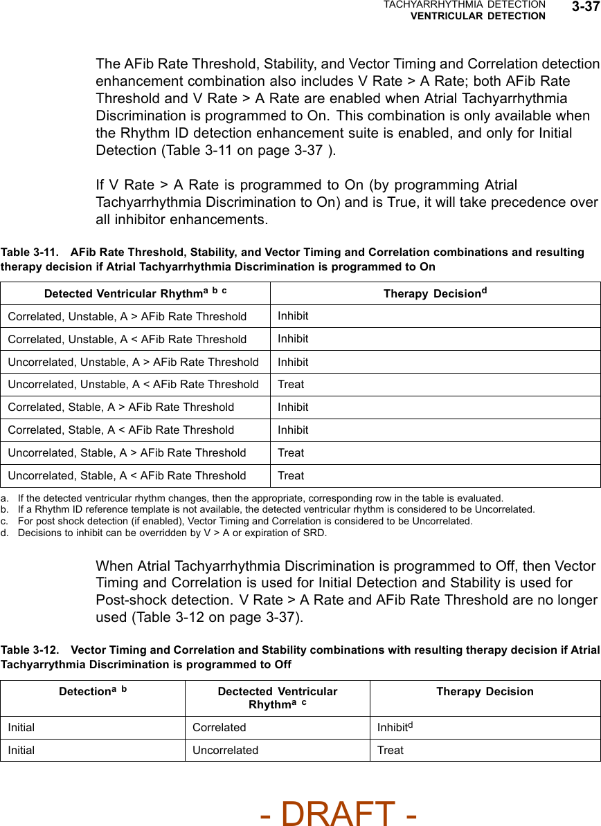

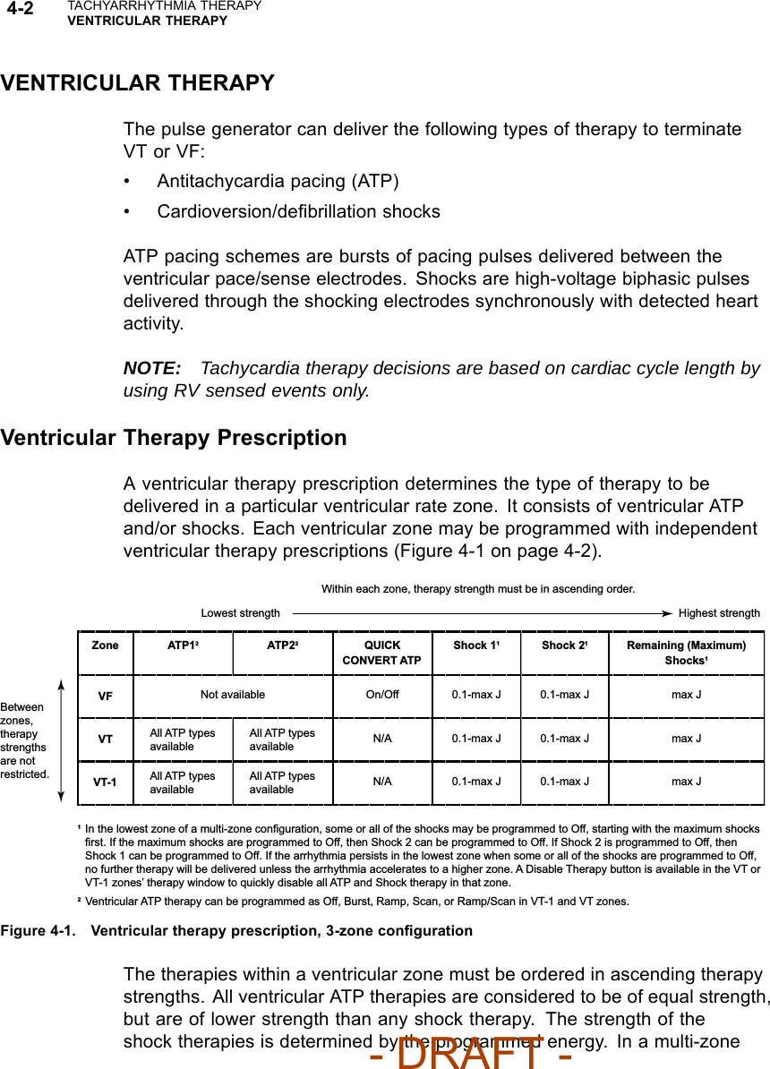
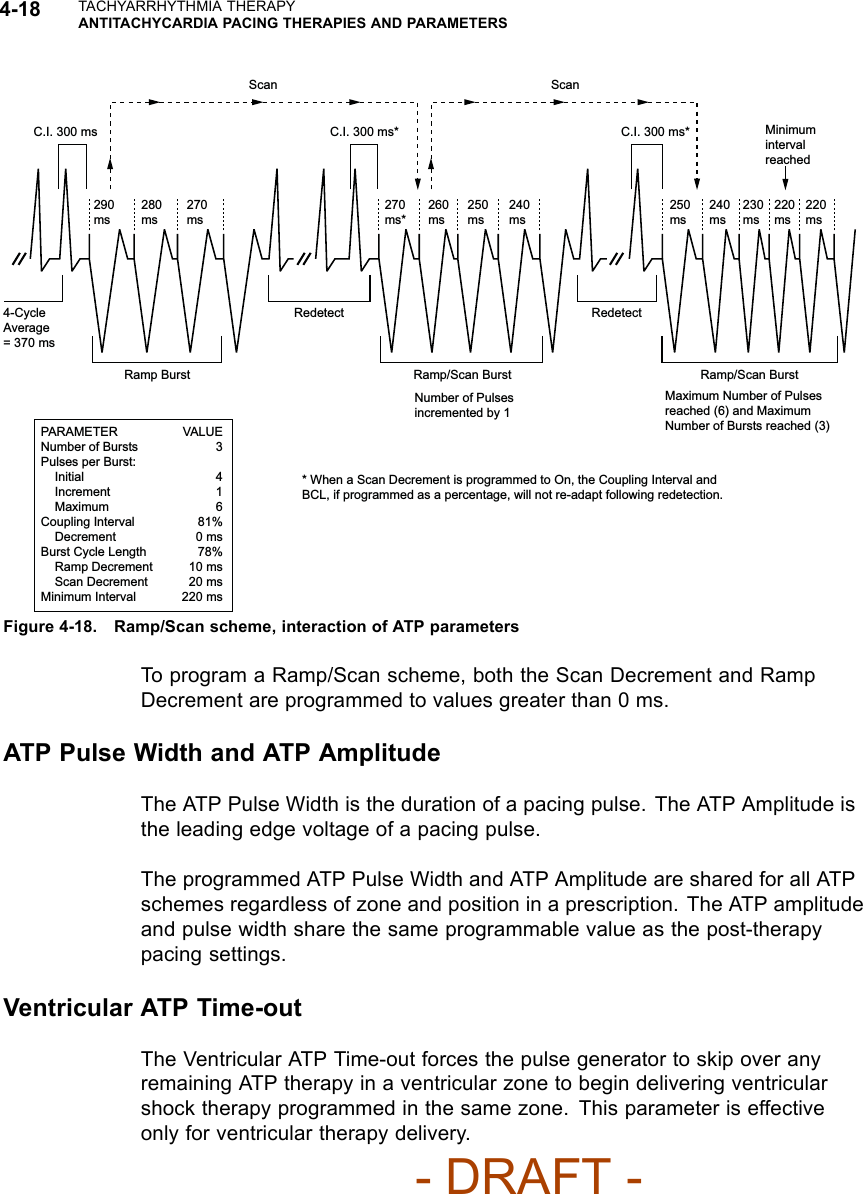
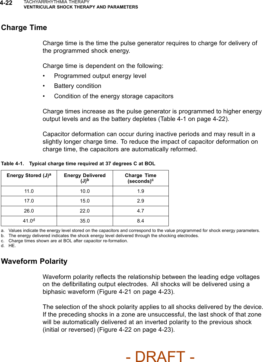


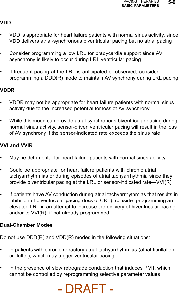
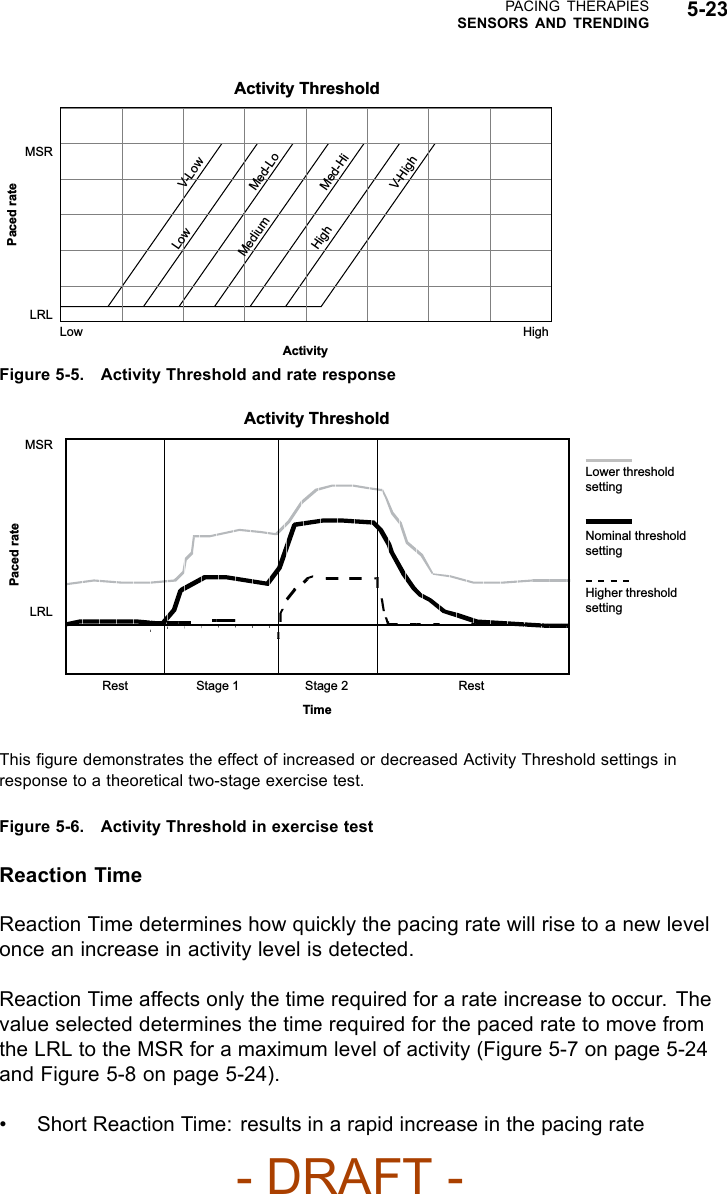
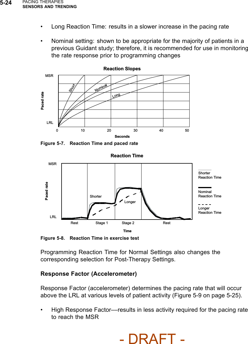
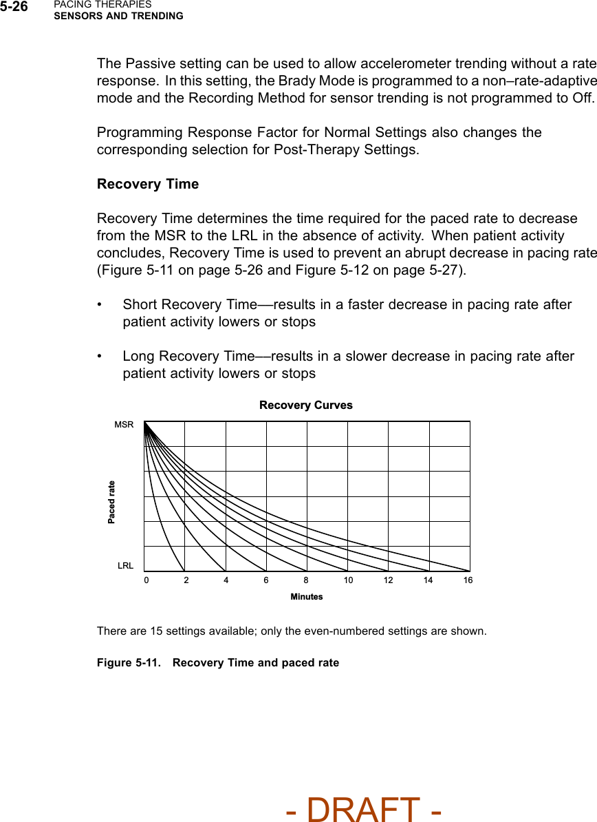
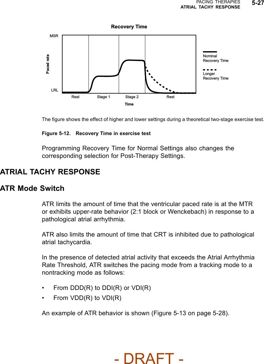
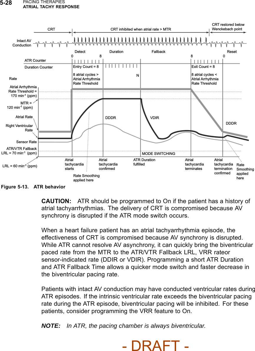
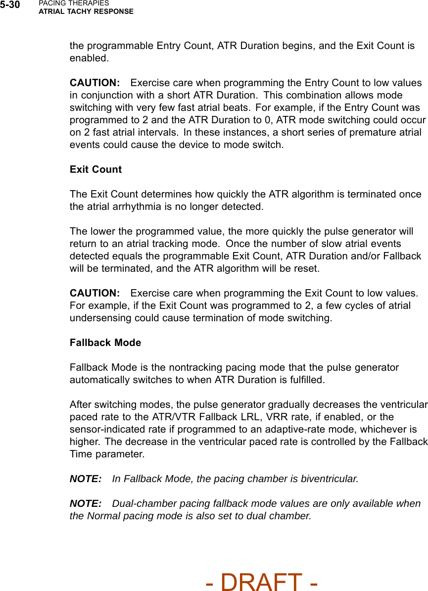
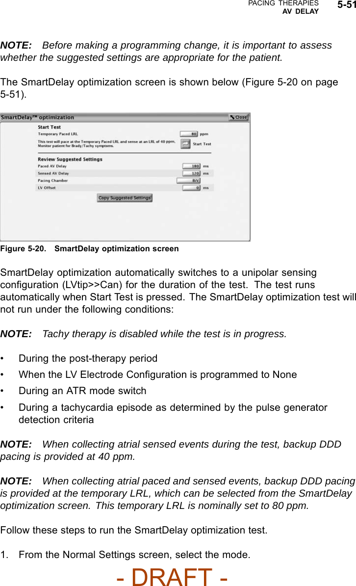
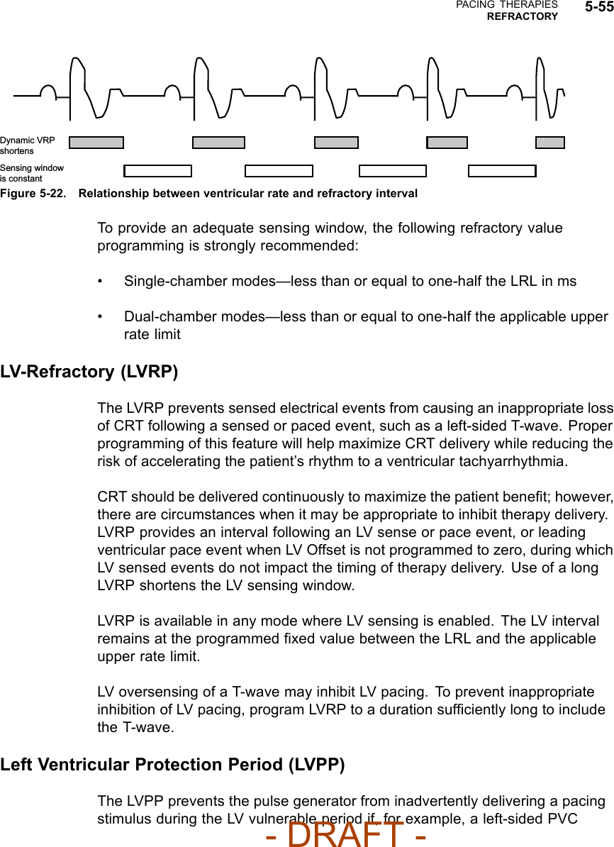
![PACING THERAPIESMAINTAINING CRT 5-5• Medical management of fast atrial rates can maximize the amount of timethat the patient remains below MTR and help ensure consistent CRTdeliveryNOTE: If a patient has slow VT, the ability to program higher MTR values islimited by the lower rate threshold of the lowest tachyarrhythmia zone.For CRT delivery at heart rates that correspond to the slow VT rate, considermanaging the slow VT by alternate means such as antiarrhythmic drugs orcatheter ablation to ensure consistent CRT.AFRAFR may delay or inhibit an atrial paced event and prevent pacing into the atrialvulnerable period and to provide immediate fallback for atrial rates higher thanthe AFR programmable rate. This changes the AV Delay and may impact CRTeffectiveness if the AFR rate is programmed slower than the patient’s sinus rate.Rate SmoothingWhen Rate Smoothing Up is programmed to On, CRT is compromised duringepisodes of atrial rate increases exceeding the programmed value. For patientswith AV block, this occurs because Rate Smoothing Up prolongs AV Delayfrom the optimal setting (controls the biventricular pacing rate while the atrialrate increases).Features that Switch to VVI or VVI-like BehaviorVTR/ATR may result in Wenckebach-like behavior or the temporary lossof CRT. CRT delivery with programmed AV synchrony will return when theSVT/VT/VF event is resolved and a normal sinus rhythm is restored.For patients programmed to VDD with sinus rates below LRL, CRT will not besynchronized with atrial events and loss of AV synchrony will result. You caneither program a lower LRL or enable a pacing mode that provides atrial pacingwith synchronous ventricular pacing [e.g., DDD(R)], as medically appropriate.STAT PACE delivers CRT in VVI mode with a loss of AV synchrony. Thepermanent, programmed settings resume when the pulse generator isprogrammed out of STAT PACE.- DRAFT -](https://usermanual.wiki/Boston-Scientific/CRMN11906.Cognis-Part-2-Manual-fccid/User-Guide-886097-Page-41.png)
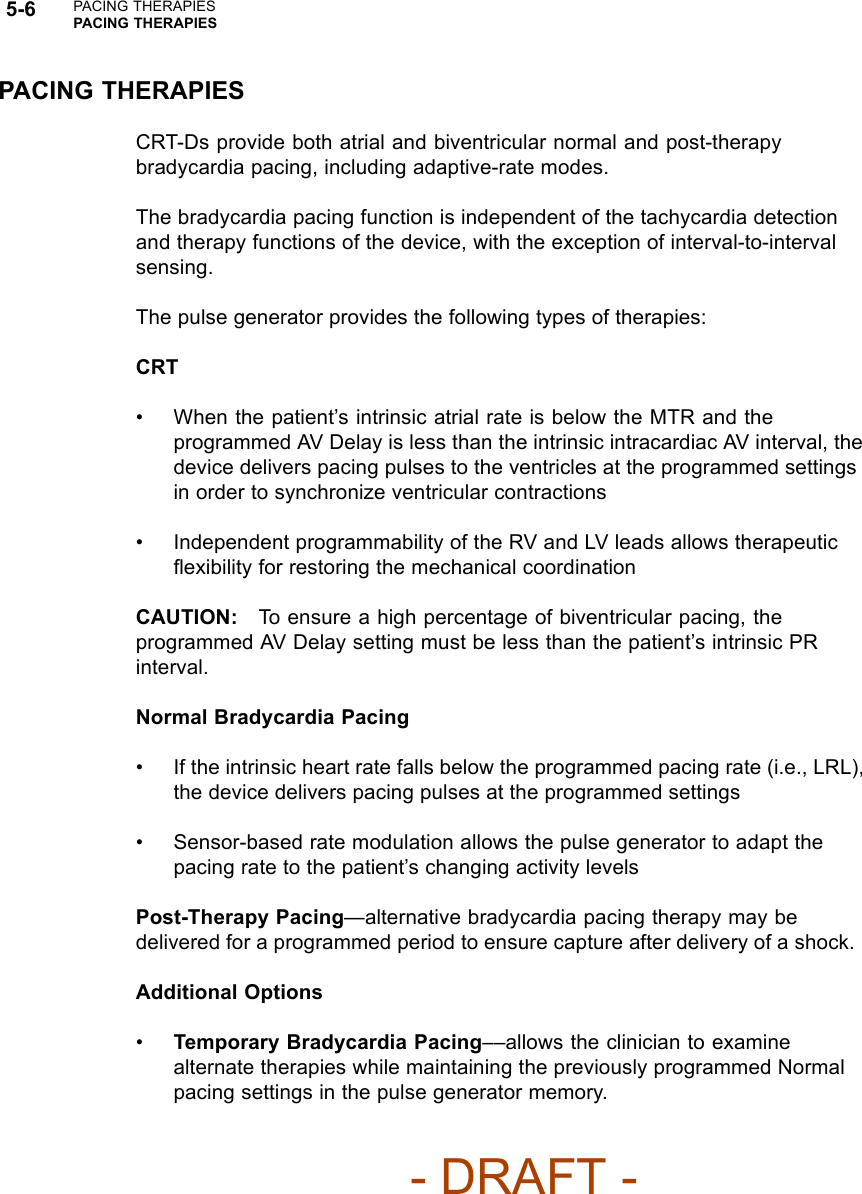
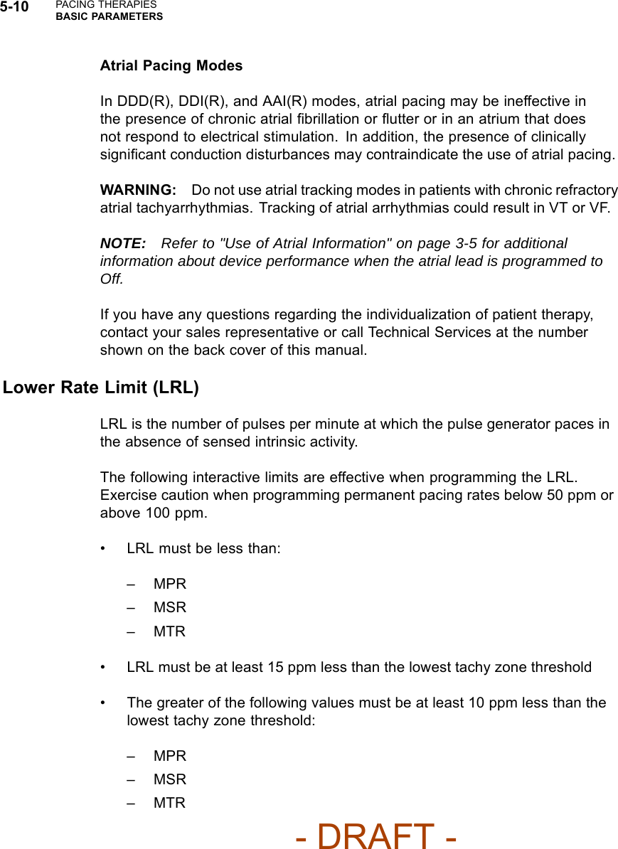
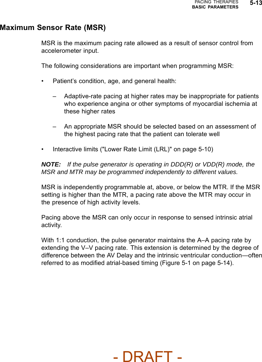
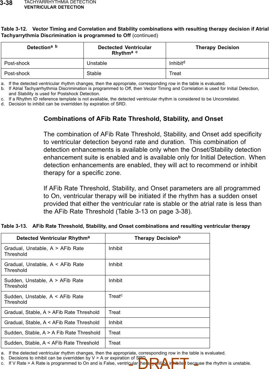
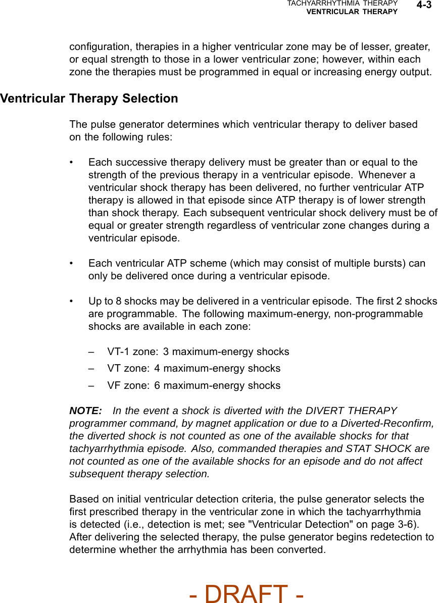
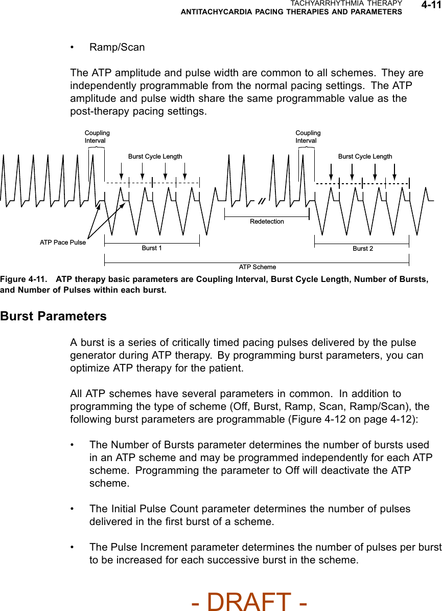
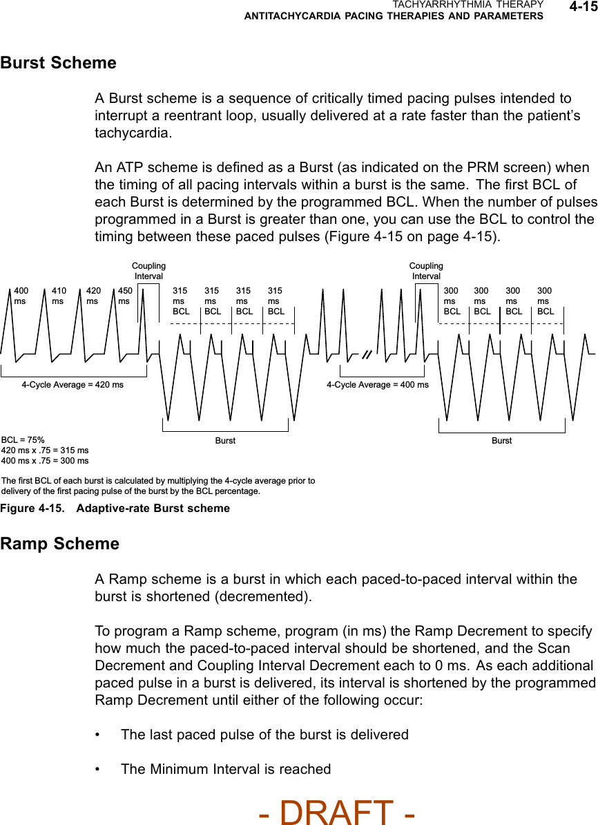
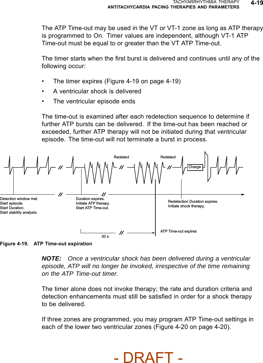
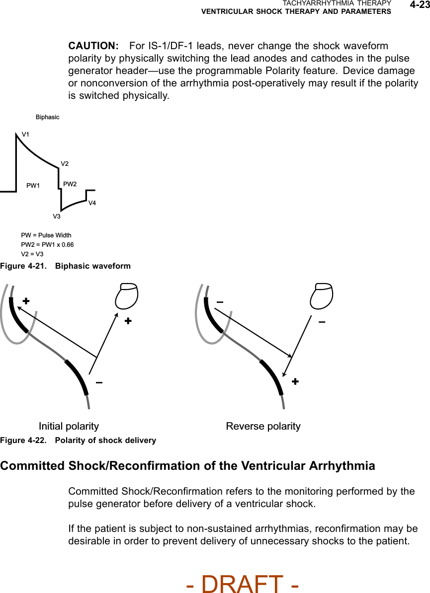
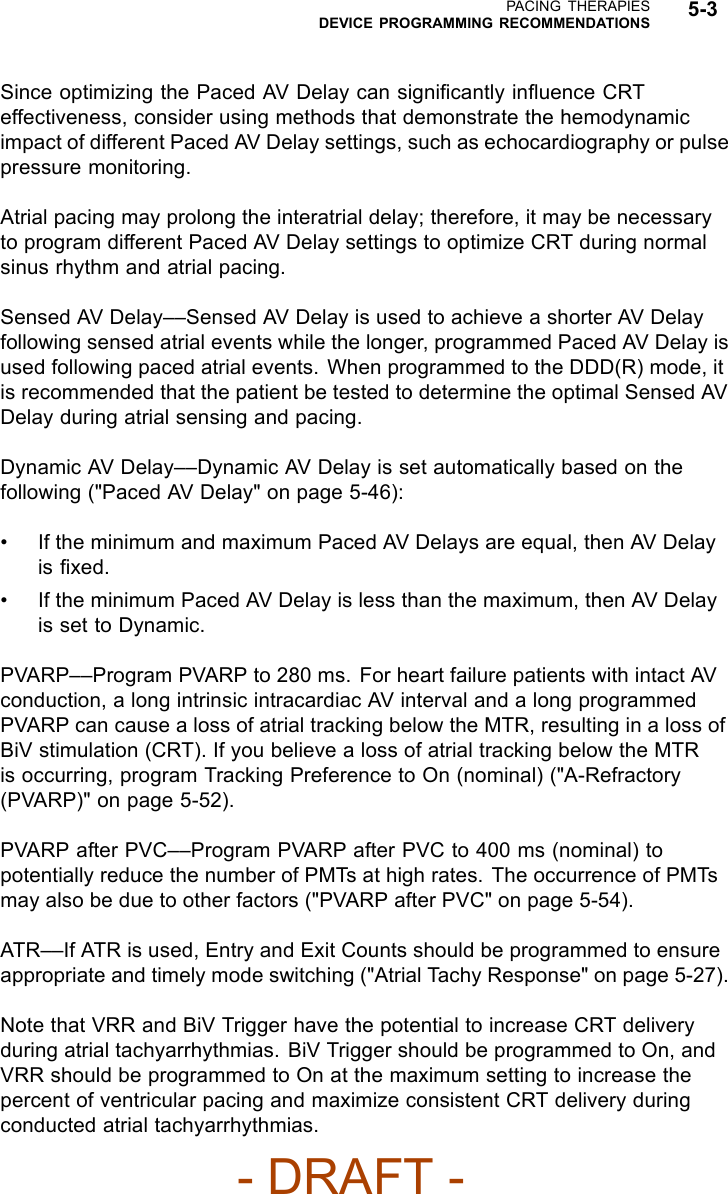
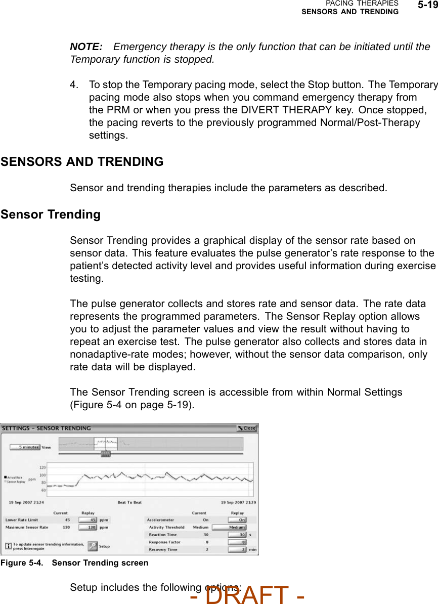
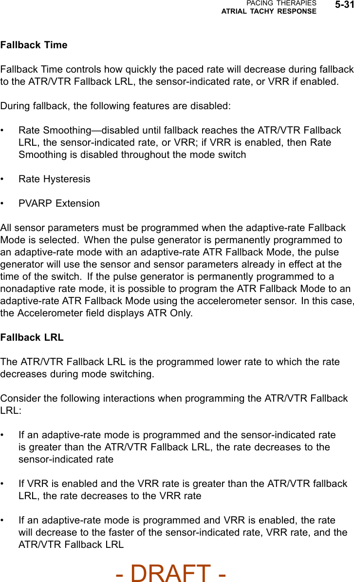
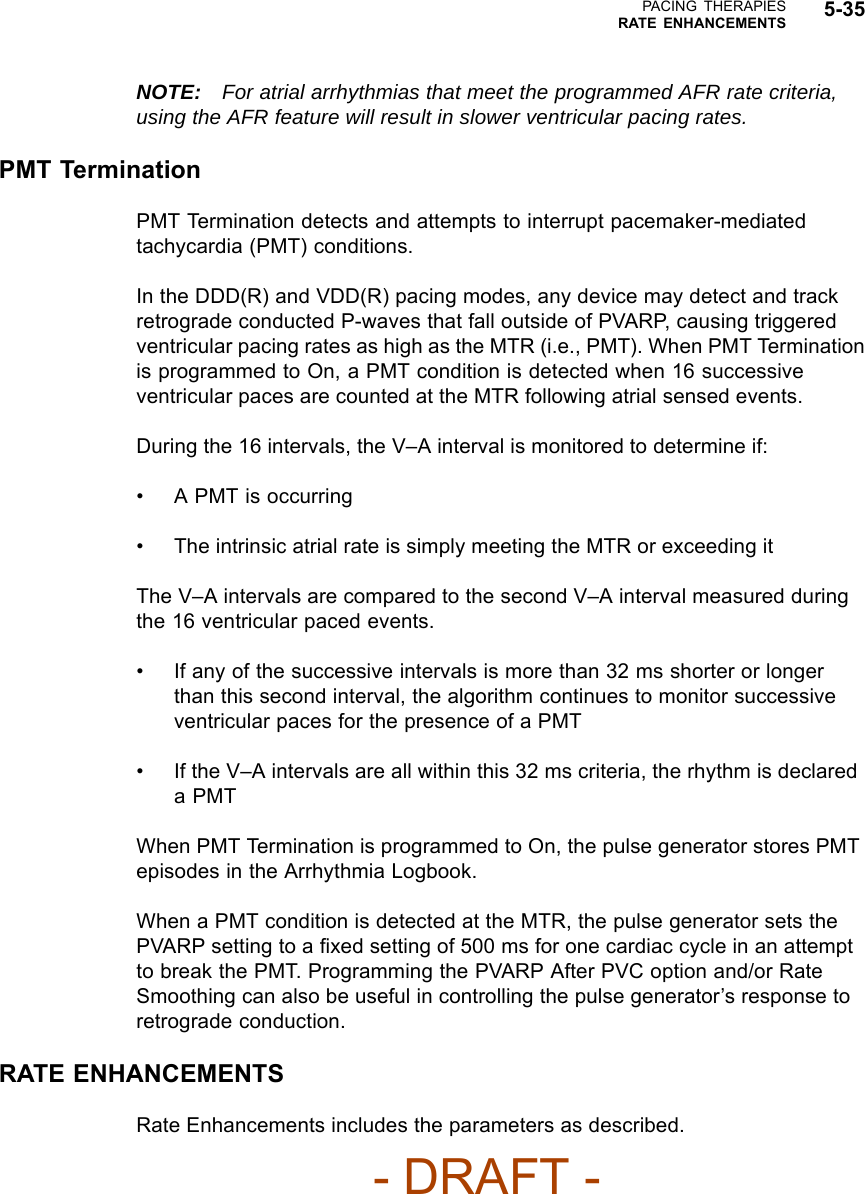
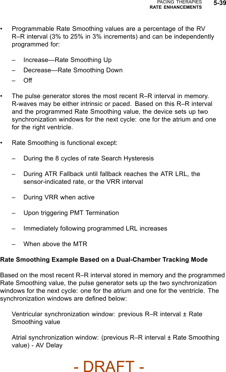
![5-14 PACING THERAPIESBASIC PARAMETERSPacing without modified right ventricular timing Pacing with modified right ventricular timing 150 200 ms AV VA AV + VA Forced extension of the V-A interval 150 200 ms AV VA AV + VA + extension MSR 400 ms (150 min-1 [ppm])AV 150 ms (conducted event)V-A 200 msPacing interval = AV + VA = 350 msMSR 400 ms (150 min-1 [ppm])AV 150 ms (conducted event)VA 200 msV-A Ext. 50 msPacing interval = AV + VA + VA extension = 400 msThe pulse generator’s timing algorithm provides effective pacing at the MSR with intrinsic ventricular conduction.Extending the VA interval prevents the A pace from exceeding the MSR at high rates.Figure 5-1. VA interval extension and MSRVentricular Pacing ChamberWith the ventricular Pacing Chamber option, you can choose which chamber(s)will receive pacing pulses.The following options are available:•RV• BiV (both RV and LV)—when selected, LV Offset becomes availableCAUTION: This device is intended to provide biventricular pacing therapy.Programming the device to provide RV-only pacing, or programming the RVpace amplitude below the pacing threshold (resulting in LV-only pacing), is notintended for the treatment of heart failure. The clinical effects of LV-only orRV-only pacing for the treatment of heart failure have not been established.LV OffsetLV Offset provides programming flexibility by allowing you to adjust the delaybetween delivery of the LV and RV pacing pulses.- DRAFT -](https://usermanual.wiki/Boston-Scientific/CRMN11906.Cognis-Part-2-Manual-fccid/User-Guide-886097-Page-50.png)
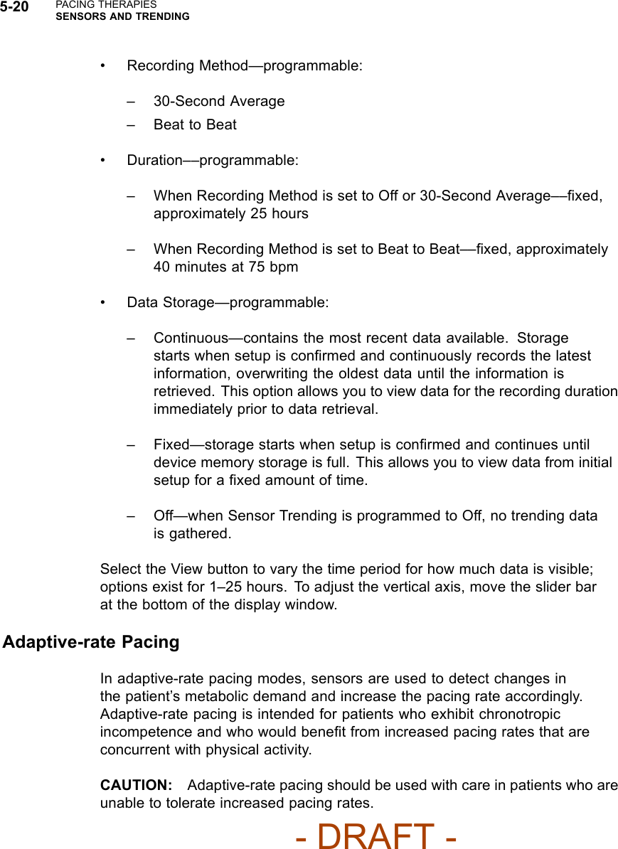
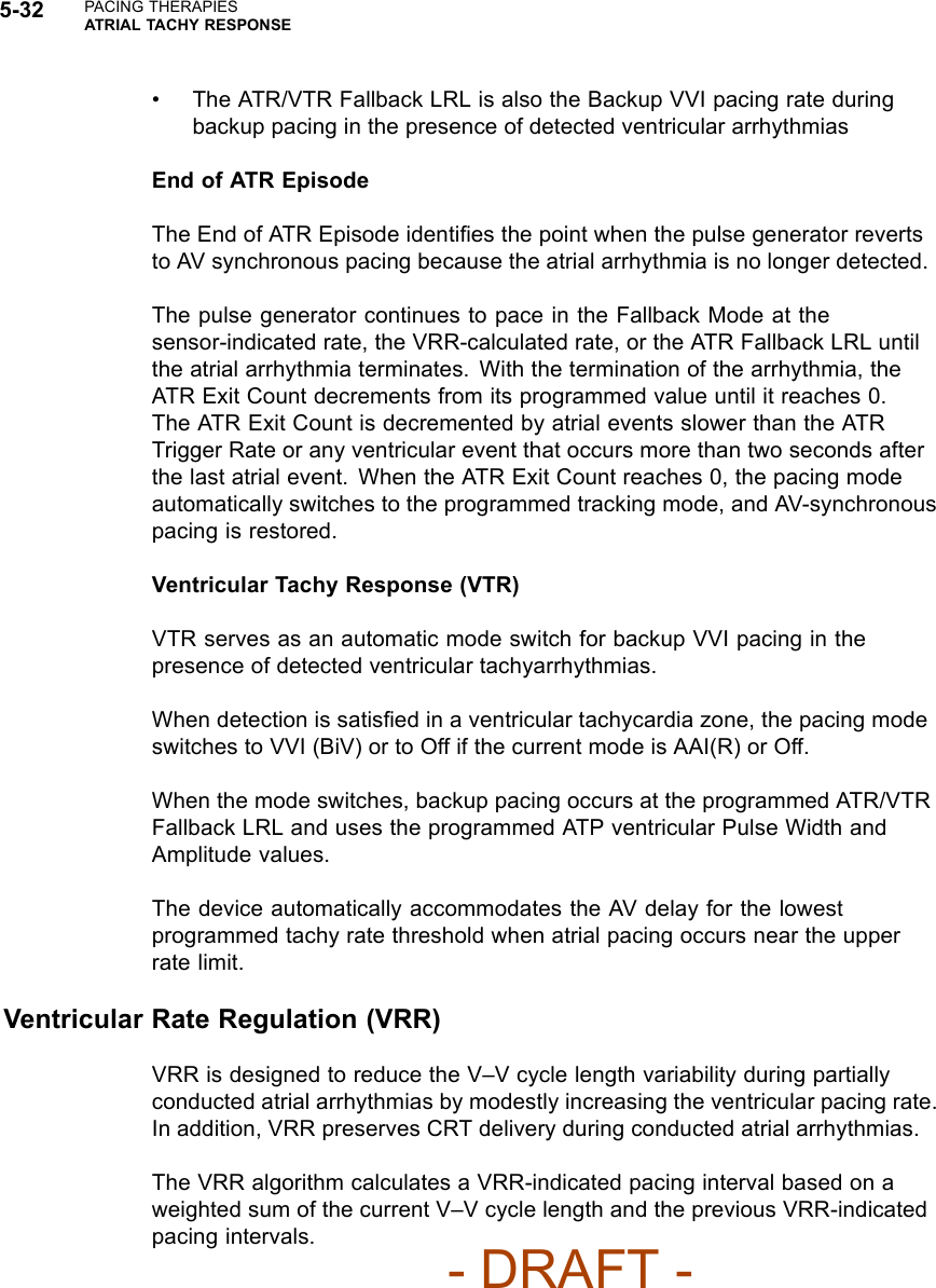
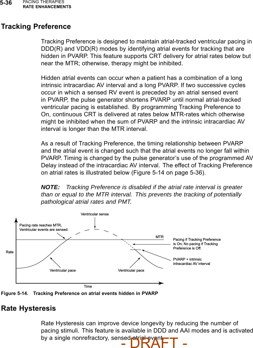
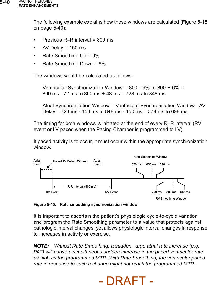
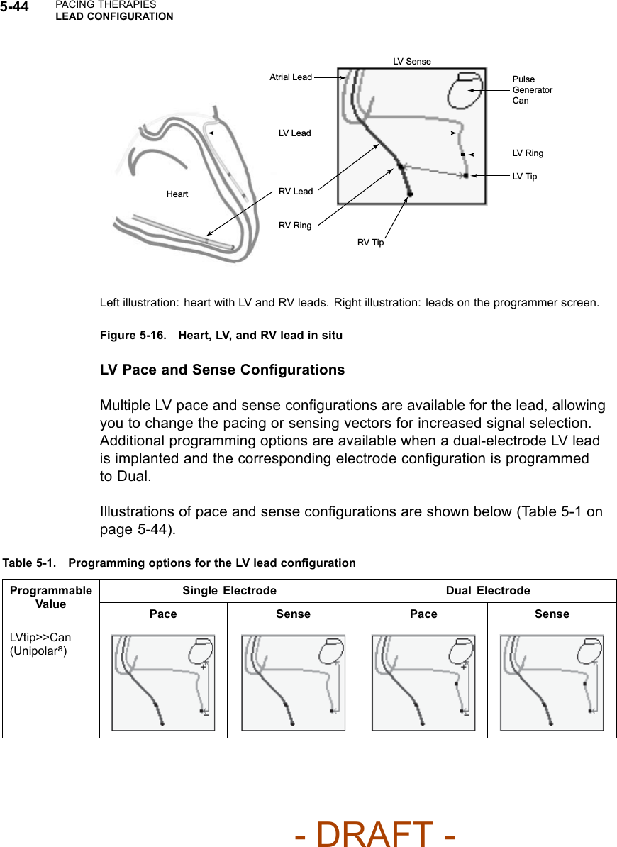
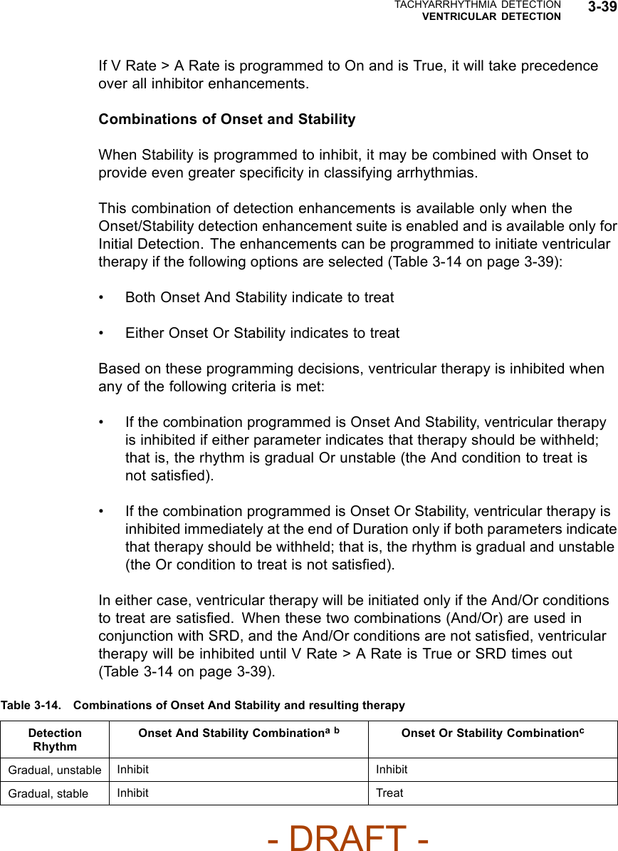
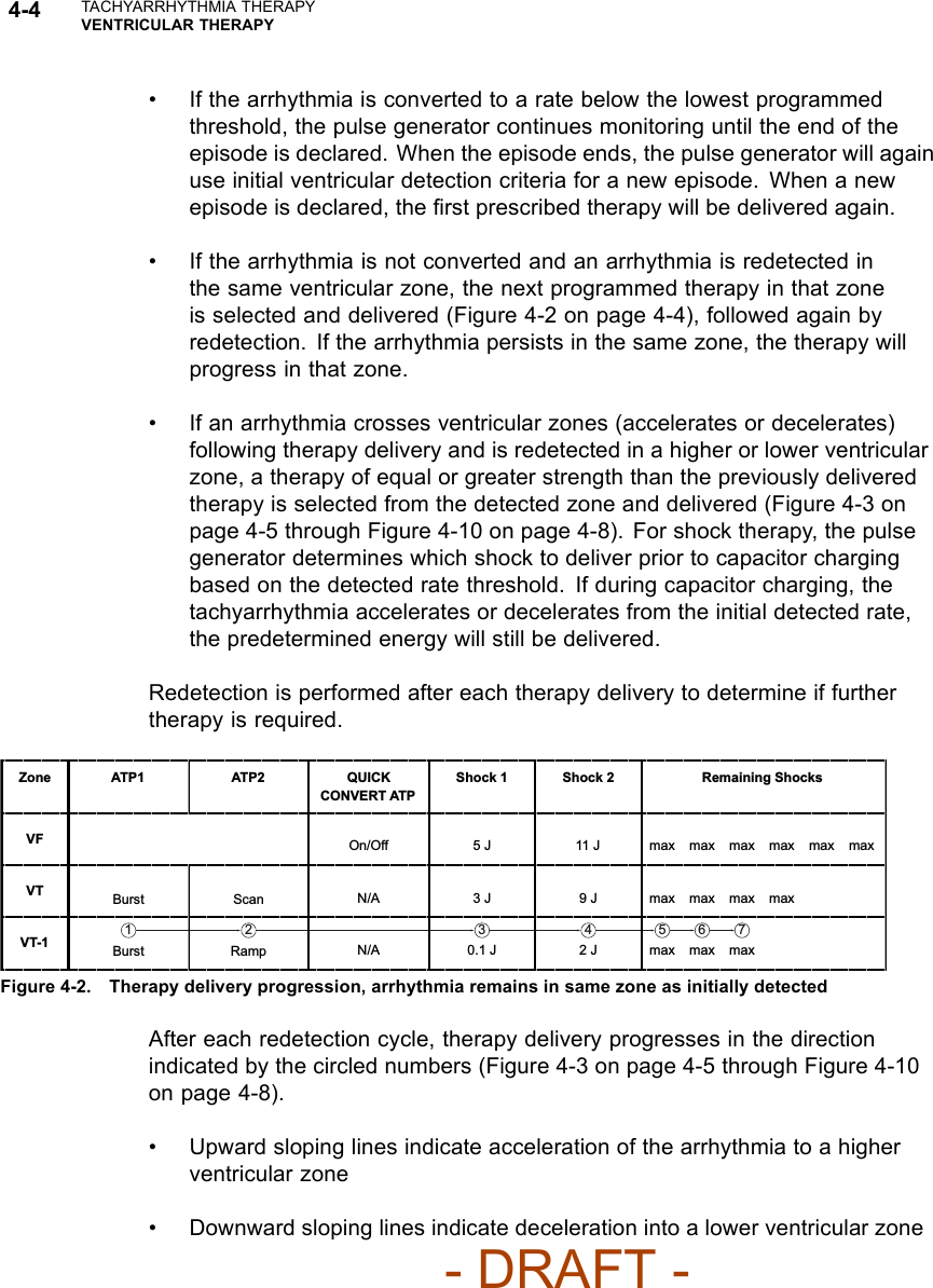
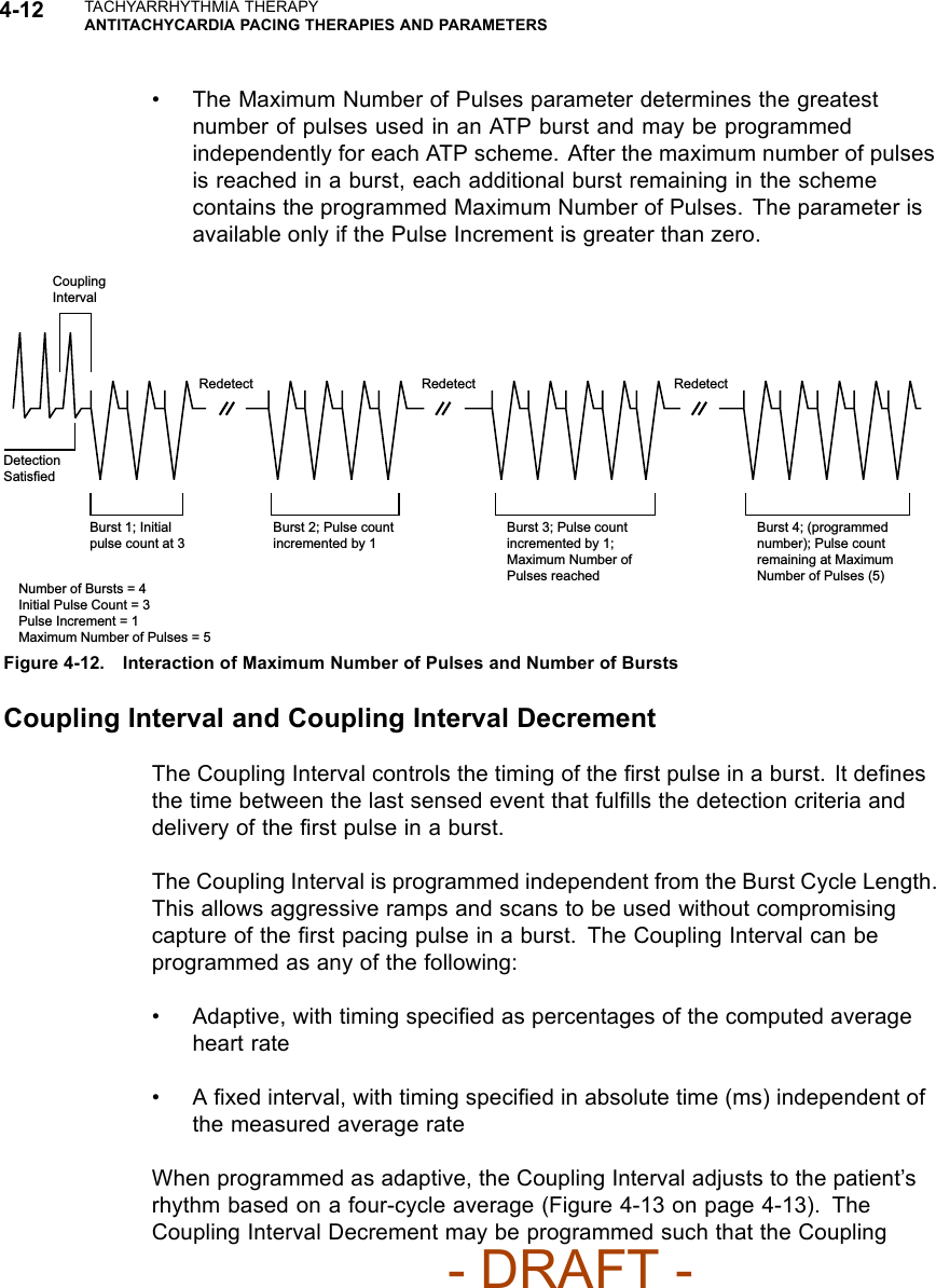
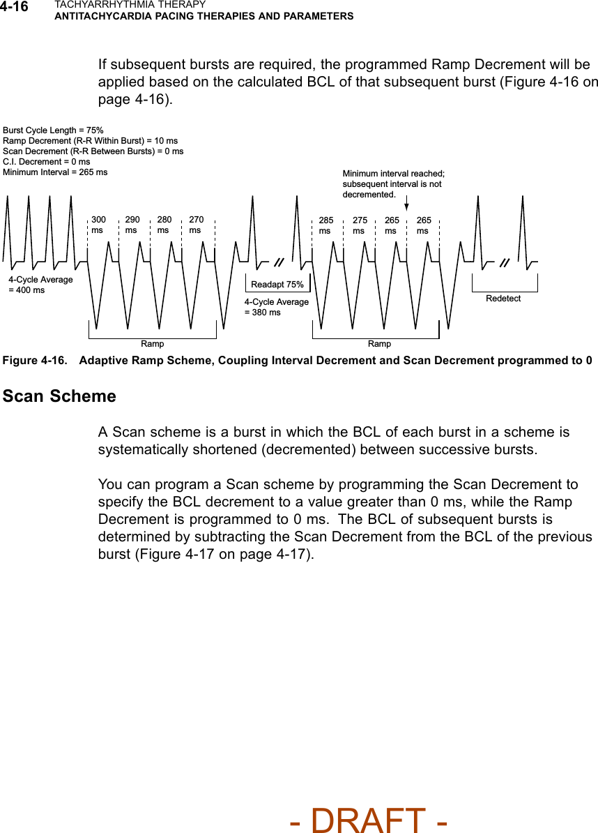
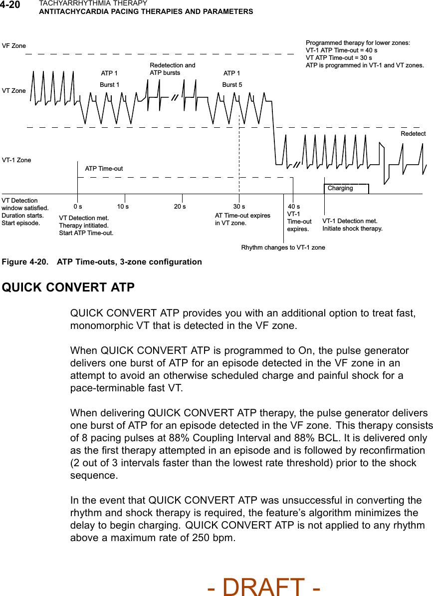
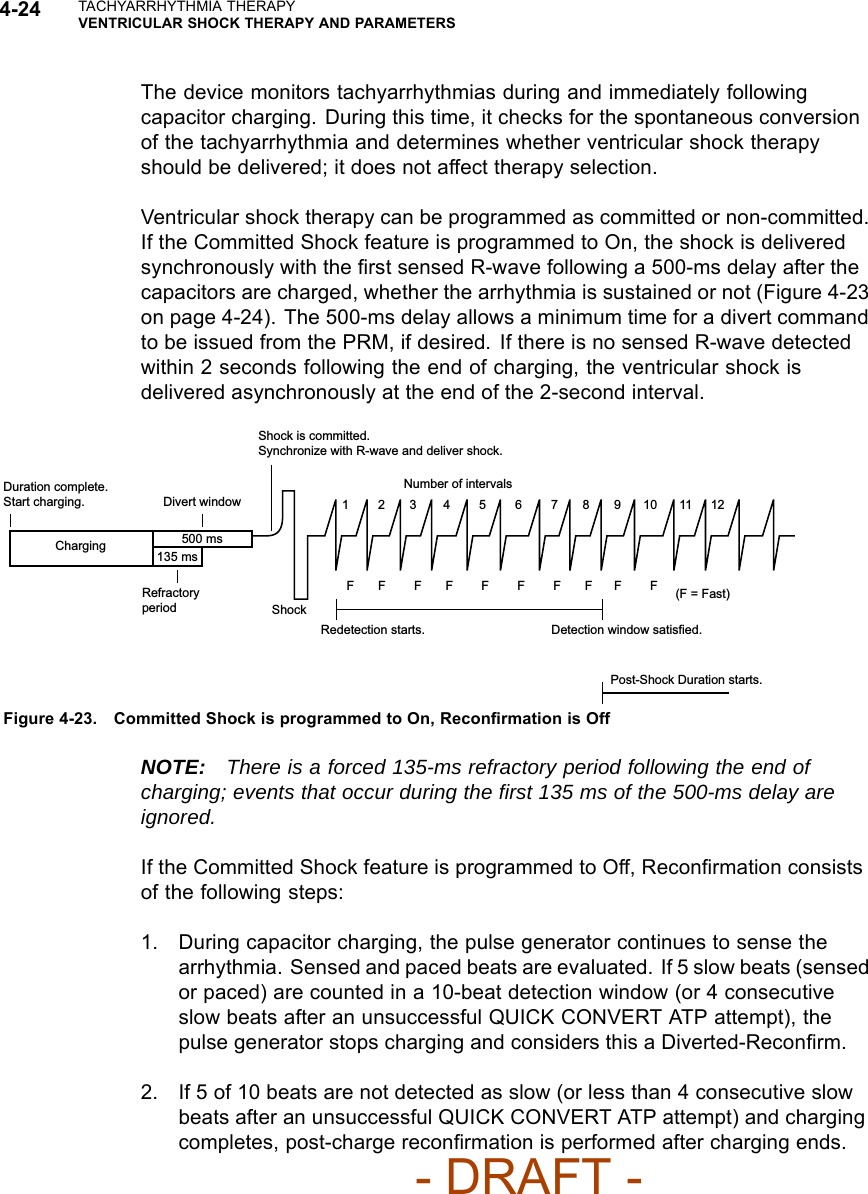
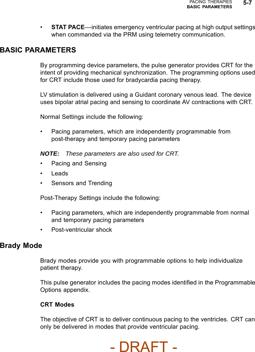
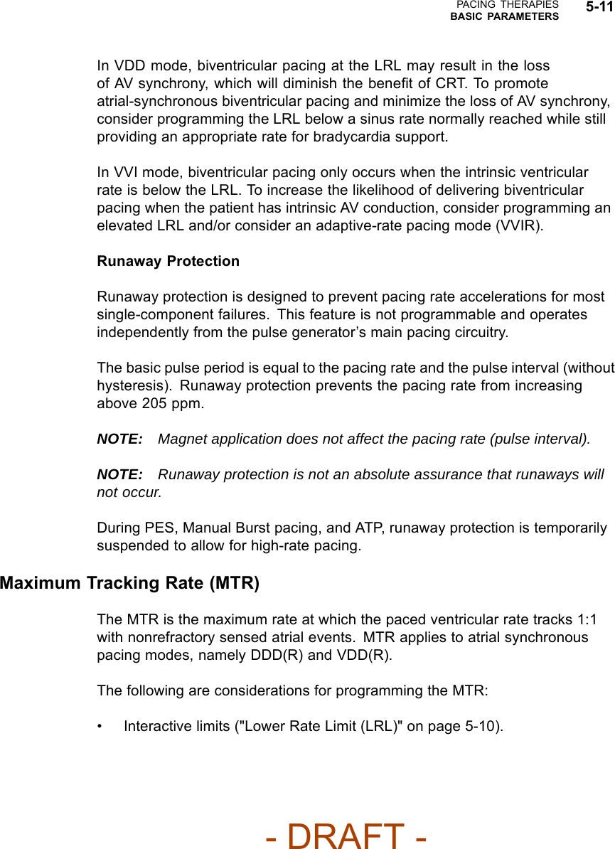
![PACING THERAPIESLEAD CONFIGURATION 5-45Table 5-1. Programming options for the LV lead configuration (continued)Single Electrode Dual ElectrodeProgrammableValue Pace Sense Pace SenseLVtip>>RV(ExtendedBipolarc)LVring>>Can(Unipolara)N/A LV OffdLVring>>RV(ExtendedBipolarc)N/A N/ALVtip>>LVring(Bipolarb)N/A N/ALVring>>LVtip(Bipolarb)N/A N/A LV Offda. Unipolar: from one of the LV electrodes to the pulse generator can.b. Bipolar: between the LV tip and the LV ring electrode; refers to a circuit where current travels between 2 electrodes locatedon the same lead—in this case, the LV lead.c. Extended Bipolar: from one of the LV electrodes to the RV electrode; refers to a circuit where current travels between the cathode(negative [–] electrode) on the LV lead and the anode (positive [+] electrode) on the bipolar RV lead.d. This configuration can be programmed to Off, which may be useful in instances such as lead fracture.- DRAFT -](https://usermanual.wiki/Boston-Scientific/CRMN11906.Cognis-Part-2-Manual-fccid/User-Guide-886097-Page-81.png)
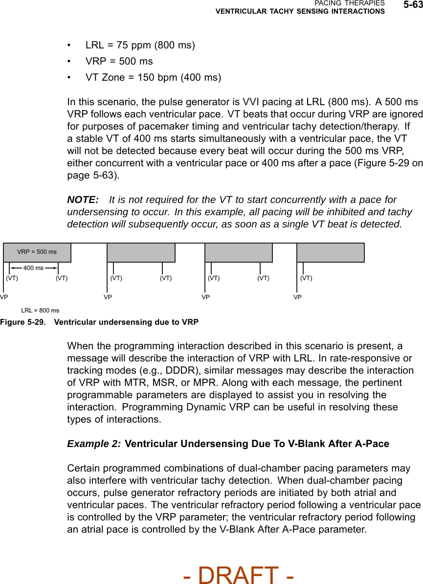
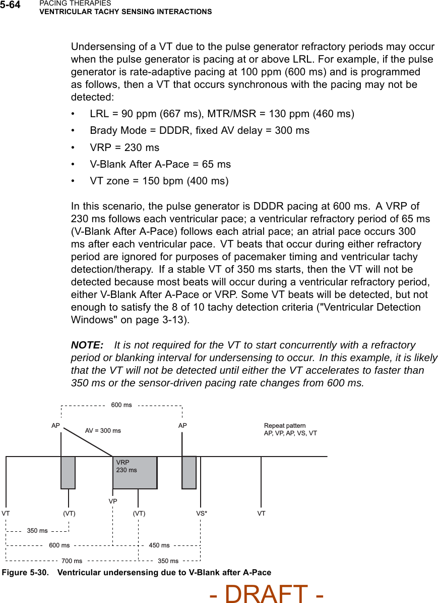
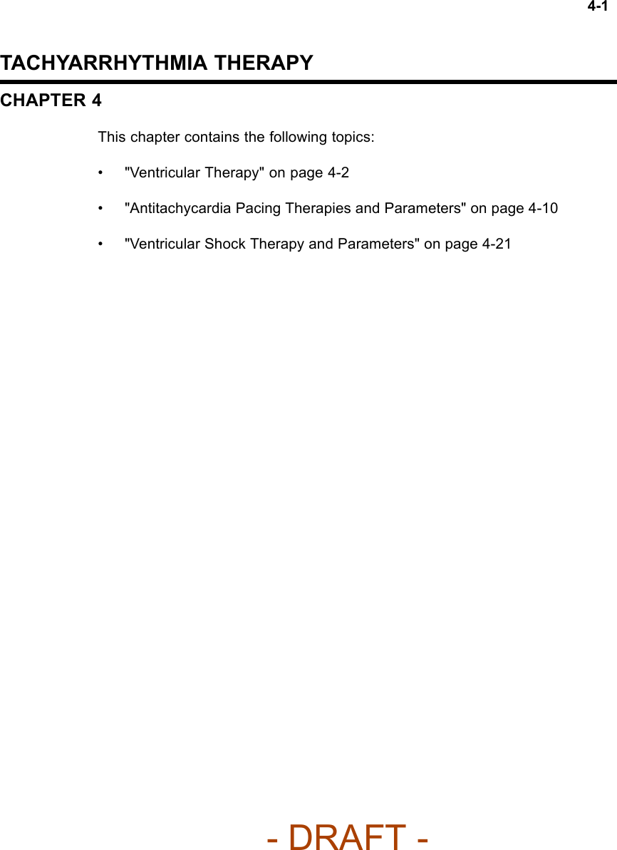
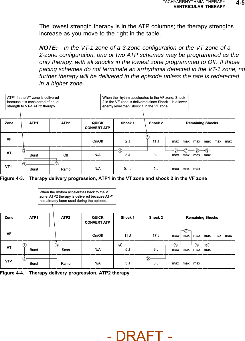
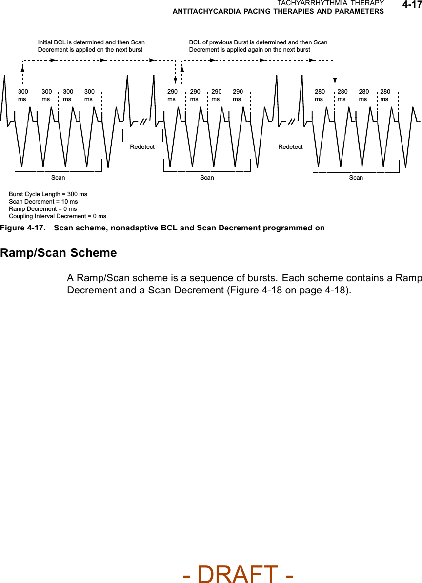
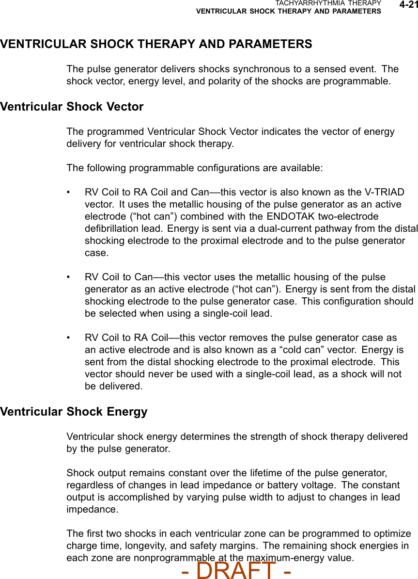
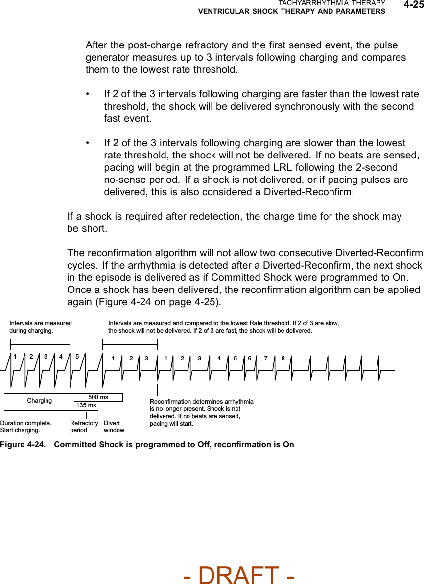
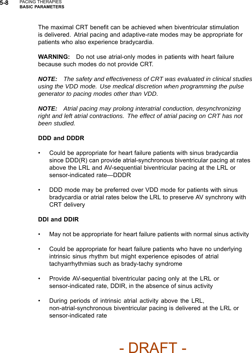
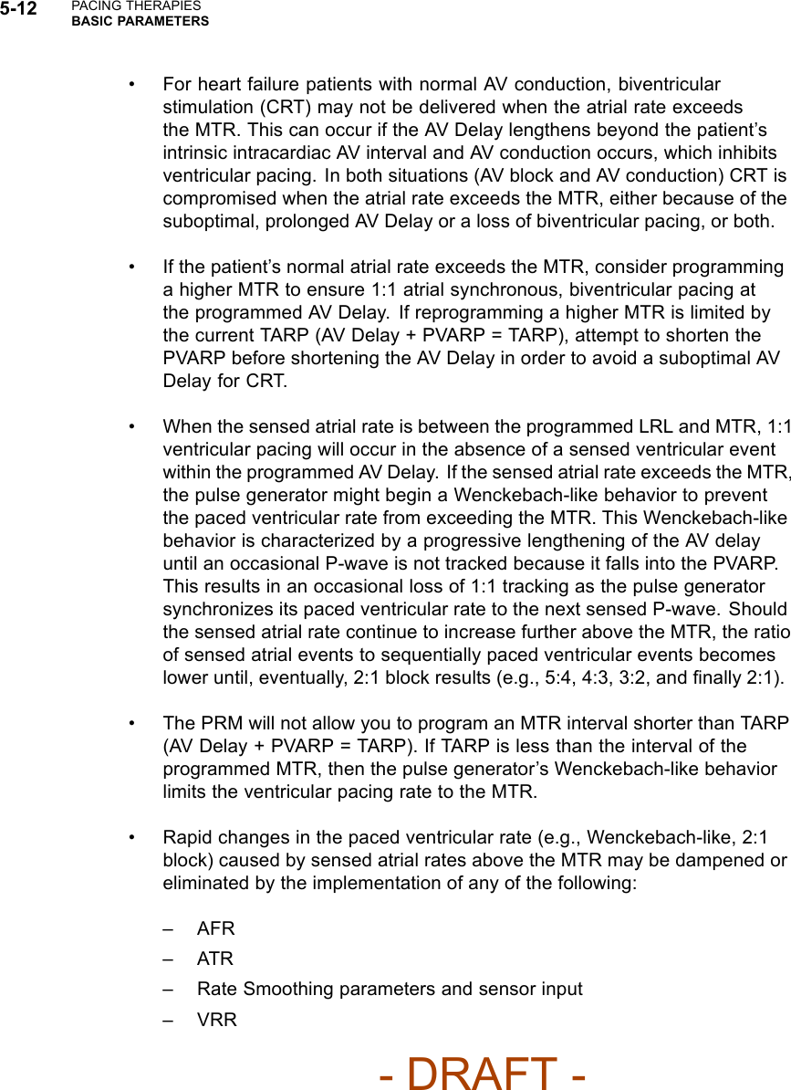
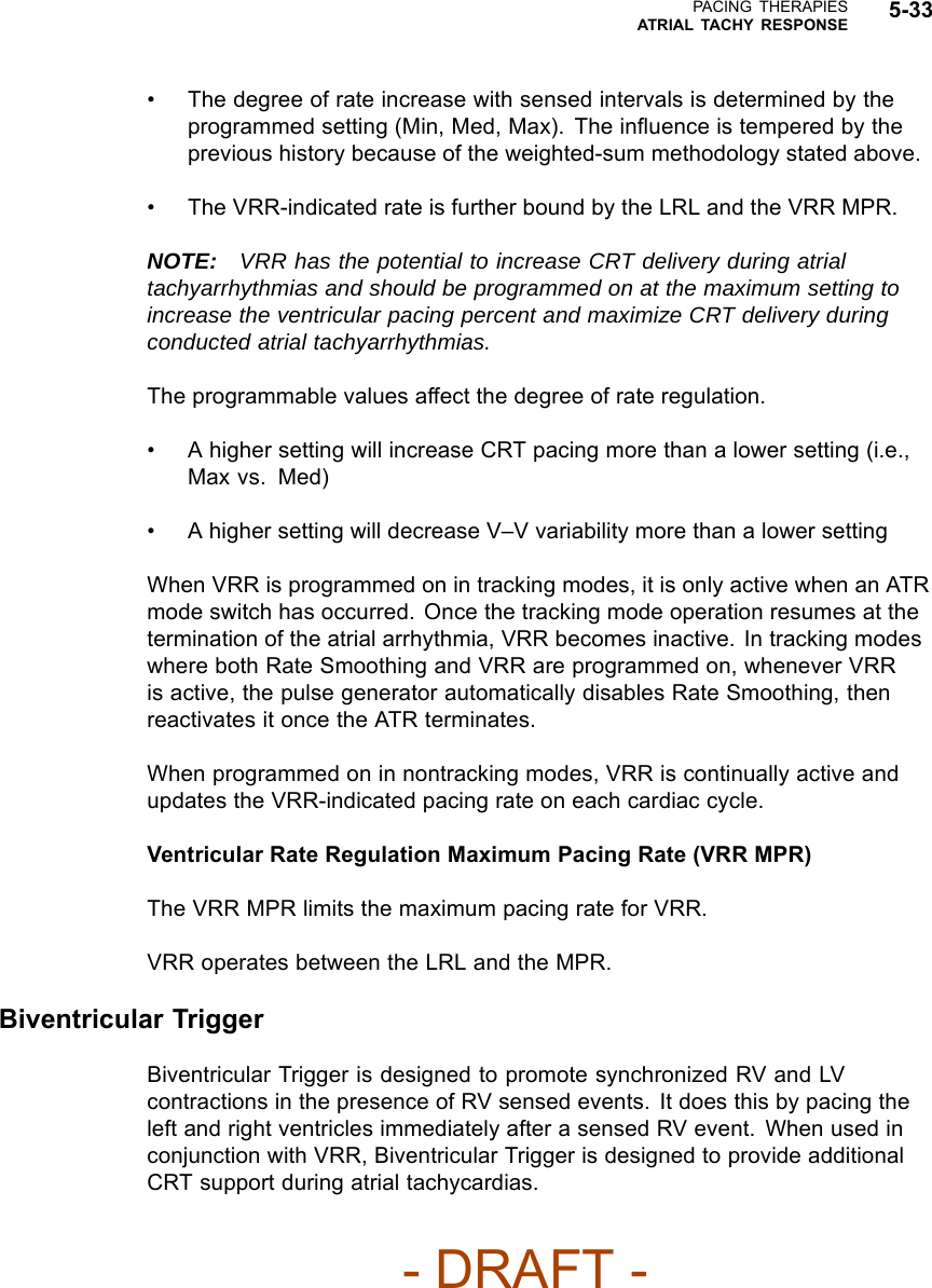
![5-62 PACING THERAPIESVENTRICULAR TACHY SENSING INTERACTIONSIf event markers are being transmitted, depending on the chamber where noiseis occurring, the marker [AS], [RVS], or [LVS] will occur when the noise windowis triggered, followed by the marker AN, RVN, or LVN if the noise window isretriggered for 340 ms. The AN, RVN, or LVN marker will occur frequently if thenoise window continuously retriggers for 340 ms.NOTE: In pacer-dependent patients, use care when considering setting NoiseResponse to Inhibit as pacing will not occur.VENTRICULAR TACHY SENSING INTERACTIONSRefractory periods and blanking intervals are an integral part of the pulsegenerator sensing system. They are used to efficiently suppress detection ofpulse generator artifacts (e.g., a pace or shock) and certain intrinsic signalartifacts (e.g., a T-wave or far-field R-wave). The pulse generator does notdiscriminate between events that occur during refractory periods and blankingintervals. As a result, all events (pulse generator artifacts, intrinsic artifacts, andintrinsic events) that occur during a refractory period or blanking interval areignored for purposes of pacing timing cycles and ventricular tachy detection.Certain programmed combinations of pacing parameters are known to interferewith ventricular tachy detection. When an intrinsic beat from a VT occurs duringa pulse generator refractory period, the VT beat will not be detected. As aresult, detection and therapy of the arrhythmia may be delayed until enough VTbeats are detected to satisfy the tachy detection criteria ("Ventricular DetectionWindows" on page 3-13).Pacing Parameter Combination ExamplesThe following examples illustrate the effects of certain pacing parametercombinations on ventricular sensing. When programming pulse generatorpacing and tachy detection parameters, consider the possible interactions ofthese features in light of the expected arrhythmias. In general, the PRM screendisplays Parameter Interaction Attentions and advisory messages to inform youabout programming combinations that could interact to cause these scenarios;the interactions can be resolved by reprogramming the pacing rate, AV Delayand/or refractory/blanking periods.Example 1: Ventricular Undersensing Due to Ventricular Refractory PeriodIf the pulse generator is programmed as follows, a VT that occurs synchronouswith the pacing will not be detected:• Brady Mode = VVI- DRAFT -](https://usermanual.wiki/Boston-Scientific/CRMN11906.Cognis-Part-2-Manual-fccid/User-Guide-886097-Page-98.png)