Boston Scientific CRMN11906 Implantable Defibrillator User Manual Teligen Part 1 Manual
Boston Scientific Corporation Implantable Defibrillator Teligen Part 1 Manual
UserManual.wiki
>
Boston Scientific
>
CRMN11906 User Manual
>
Teligen Part 1 Manual
Contents
1.
Cognis Part 1 Manual
2.
Cognis Part 2 Manual - fccid
3.
Cognis Part 3 Manual
4.
Cognis Part 4 Manual
5.
Teligen Part 1 Manual
6.
Part 2 Teligen Manual
Teligen Part 1 Manual
Navigation menu
Upload a User Manual
Namespaces
Wiki Guide
HTML
PDF
Info
Views
User Manual
Discussion / Help
Navigation


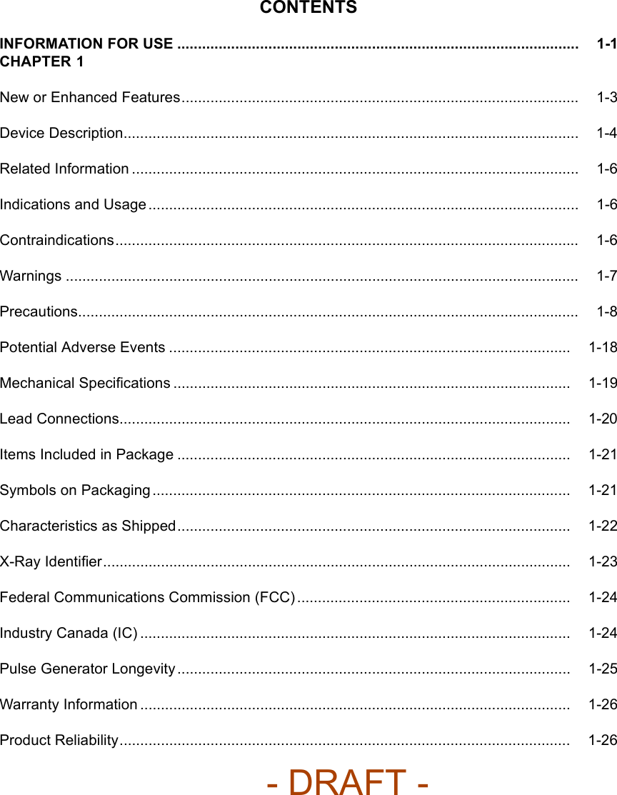
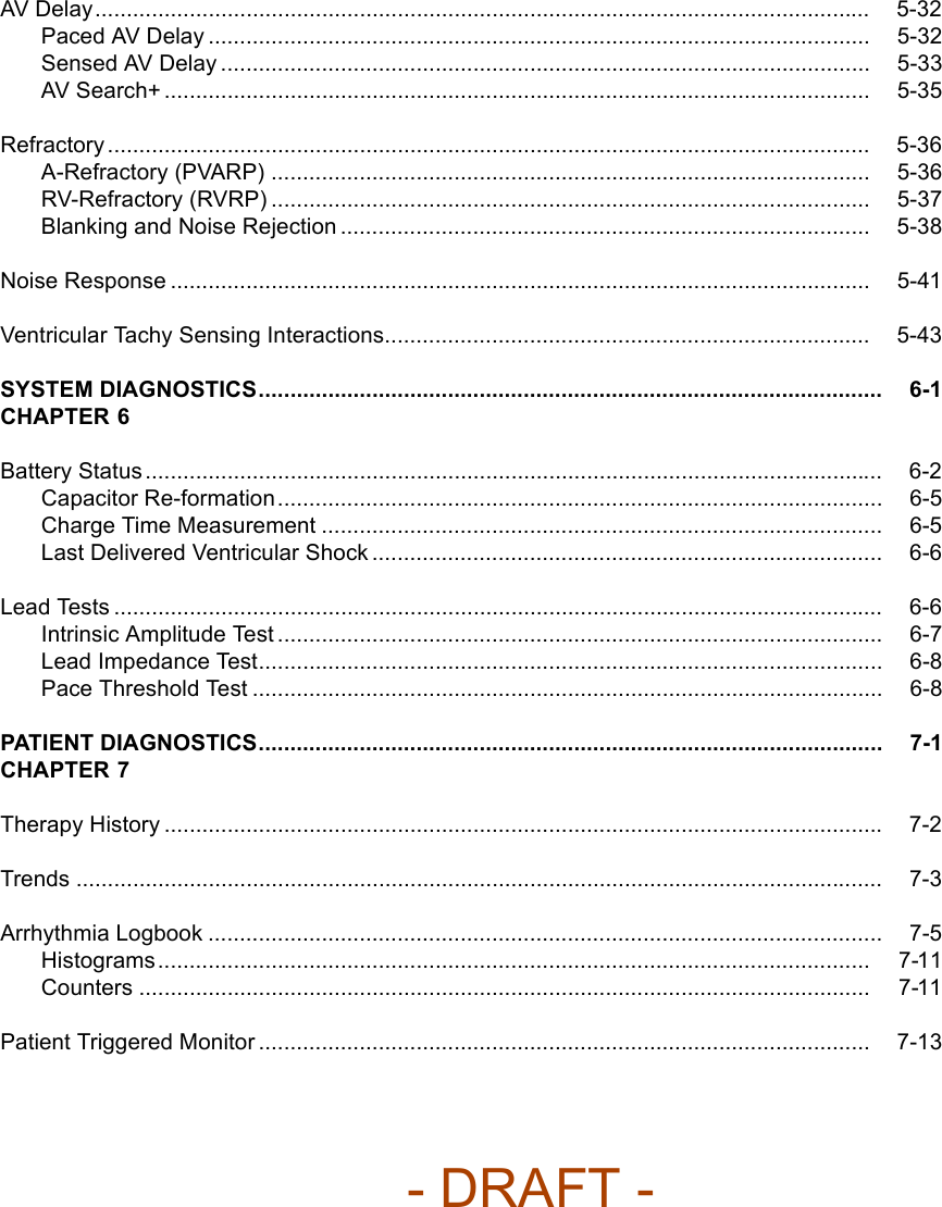
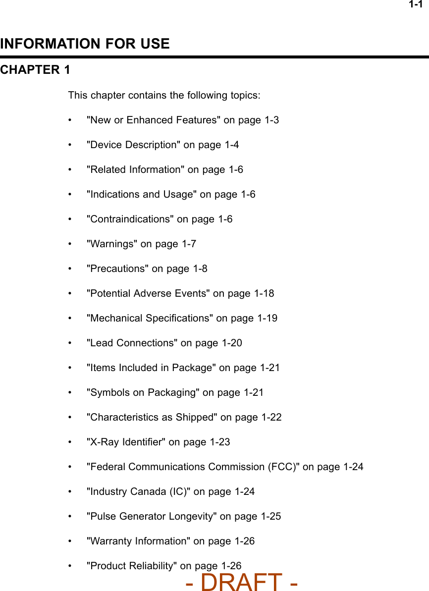

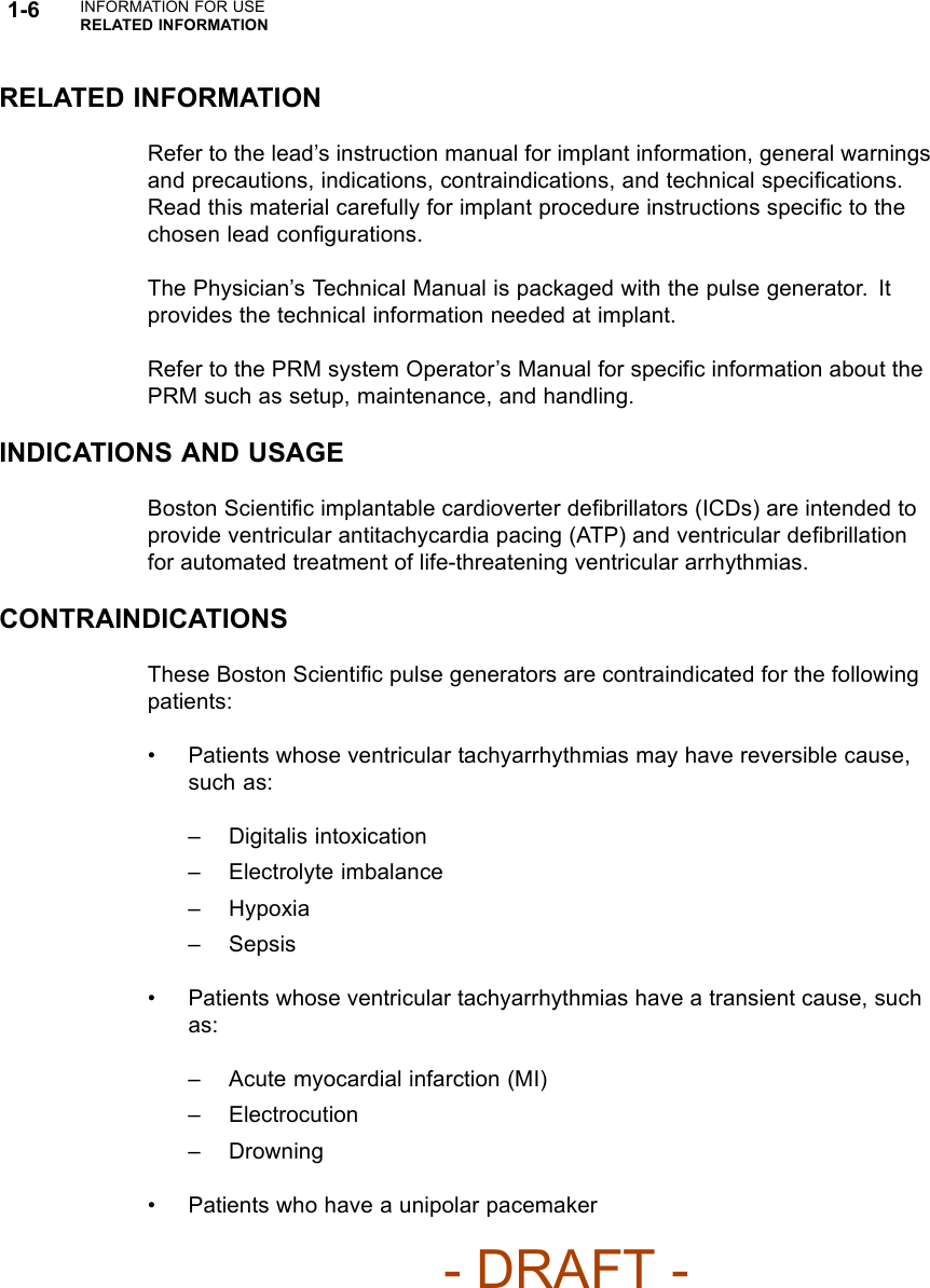
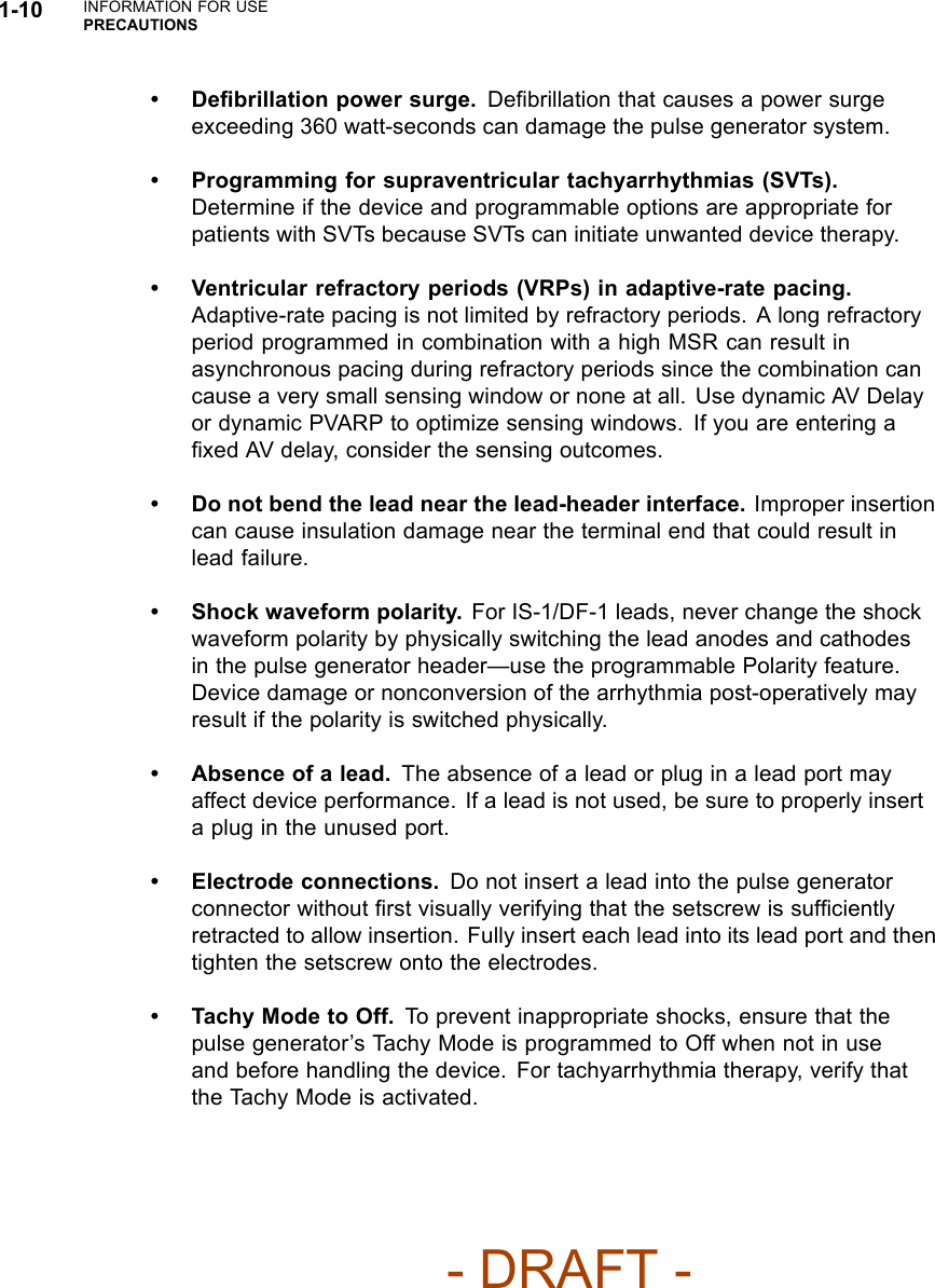
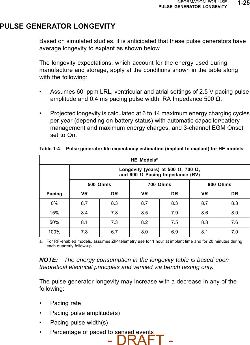
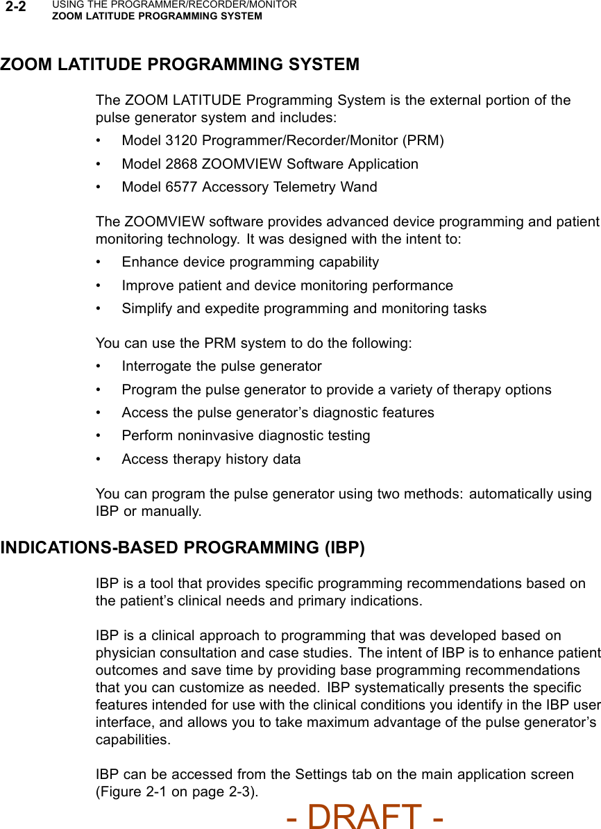
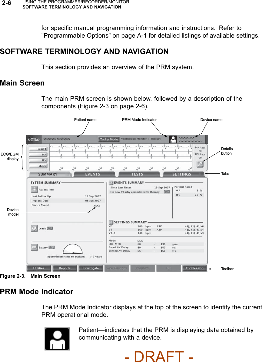

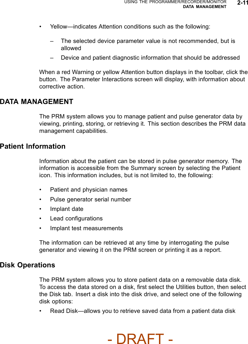
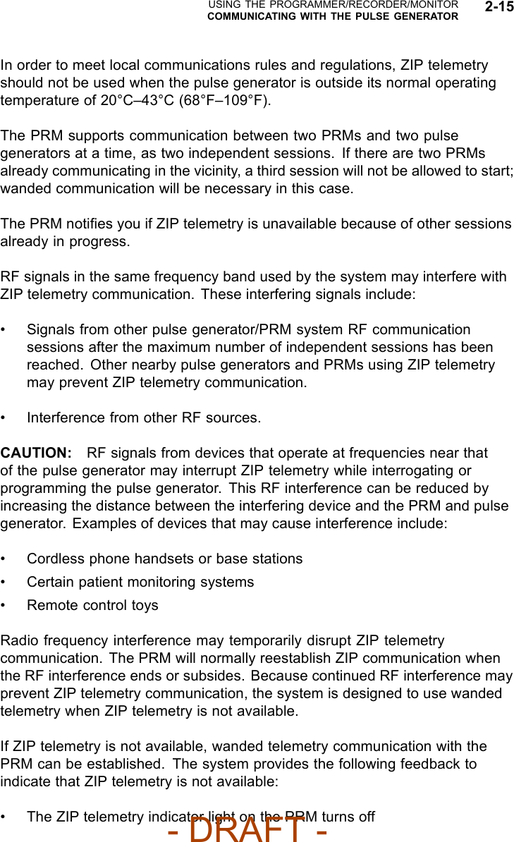
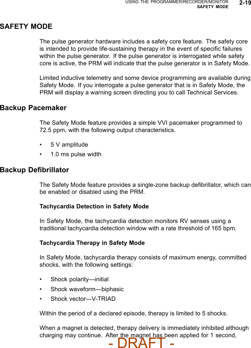
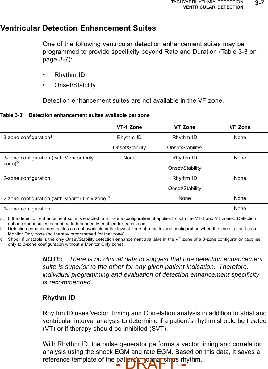

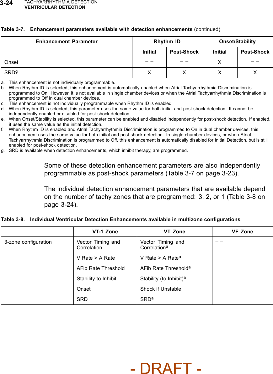
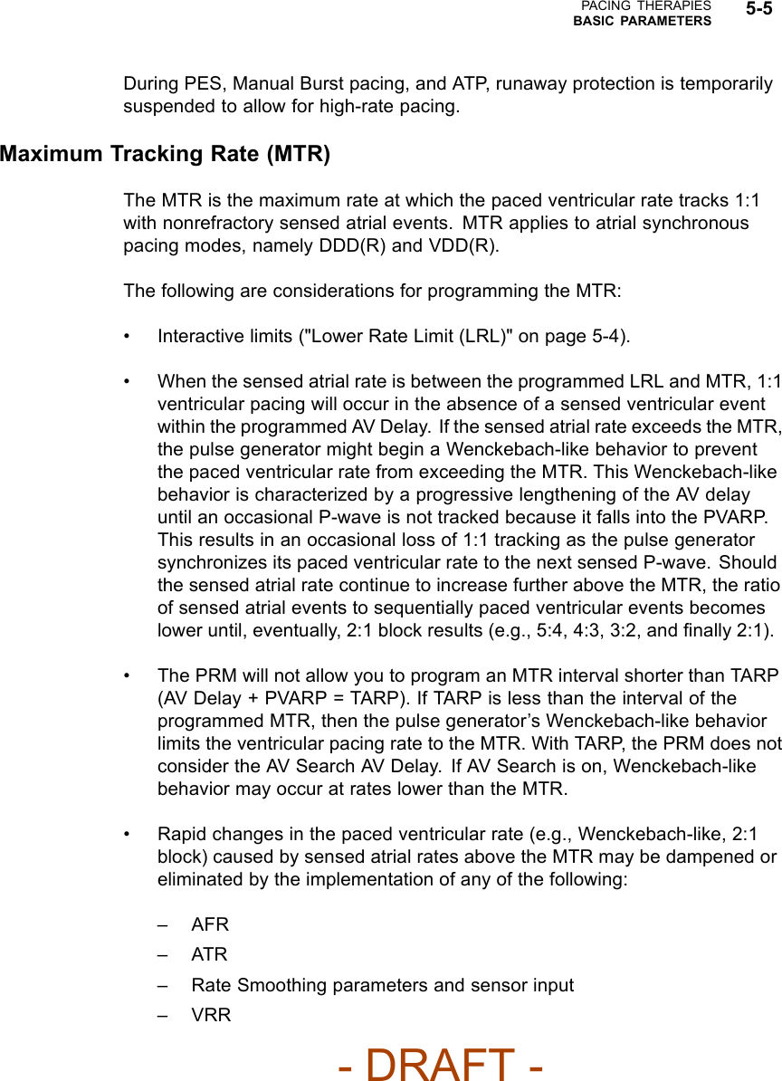
![3-28 TACHYARRHYTHMIA DETECTIONVENTRICULAR DETECTION400 380 420 390 410 400 360 440 410 390 580 620 600 640 560 600 580 600 620 1 2 3 4 5 6 7 8 9 1 2 3 4 5 6 7 8 Number of Intervals Intervals in ms Third fast interval (of the 8 out of 10 that satisfy the detection window) Start Duration. Evaluate Onset. Compute the sum of 10 most recent ventricular intervals. Average = 400 ms = 150 min-1 (bpm).Duration expired. Onset is gradual. Analyze V Rate > A Rate. Deliver therapy because V > A. Average ventricular rate (150 min-1 [bpm]) is greater than average atrial rate (100 min-1 [bpm]) by at least 10 bpm, so delivery therapy.Compute the sum of the atrial intervals. Average = 600 ms = 100 min-1 (bpm).Number of Intervals Intervals in ms Atrium Ventricle VT detected ATP therapy Figure 3-17. V Rate > A Rate analysisV Rate > A Rate can be programmed to bypass inhibitors (Vector Timing andCorrelation, AFib Rate Threshold, Stability, and/or Onset) and initiate therapy inthe event that the ventricular rate is faster than the atrial rate.NOTE: Refer to "Use of Atrial Information" on page 3-5 for additionalinformation about device performance when the atrial lead is programmed toOff.NOTE: In a Rhythm ID configuration, the evaluation of V Rate > A Rate islinked to the AFib Rate Threshold. If Atrial Tachyarrhythmia Discrimination isprogrammed to Off, the AFib Rate Threshold and V Rate > A Rate detectionenhancements are not evaluated.AFib Rate ThresholdAFib Rate Threshold analysis identifies AF by comparing the atrial rate to theprogrammed AFib Rate Threshold.AFib Rate Threshold cannot be enabled without also enabling the Stabilitydetection enhancement. The device analyzes both parameters to determinewhether to withhold or deliver therapy.If the intrinsic atrial rate is greater than the AFib Rate Threshold and theventricular rhythm is classified as unstable, the ventricular rhythm is declaredto be due to AF.- DRAFT -](https://usermanual.wiki/Boston-Scientific/CRMN11906.Teligen-Part-1-Manual/User-Guide-886100-Page-90.png)


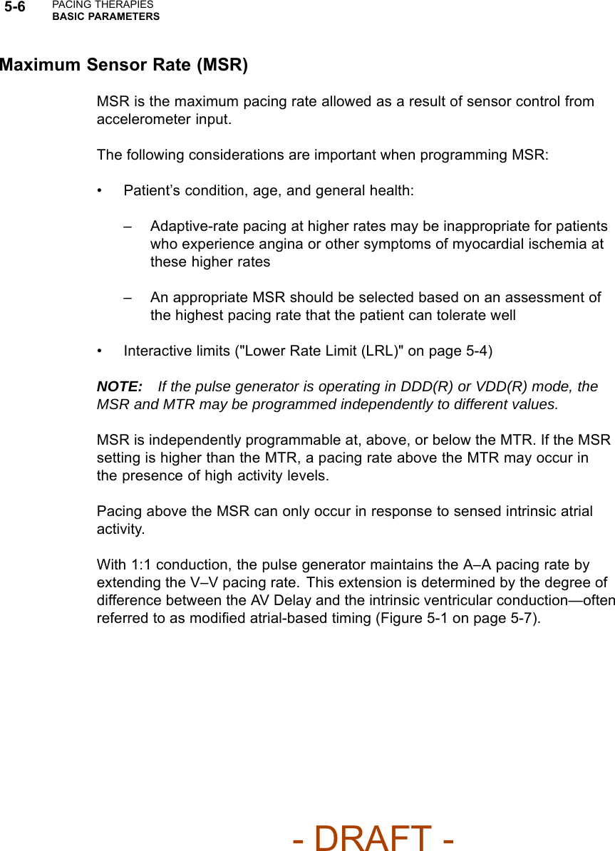
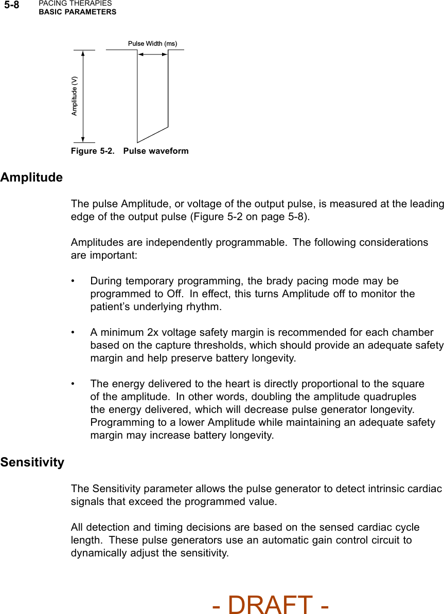
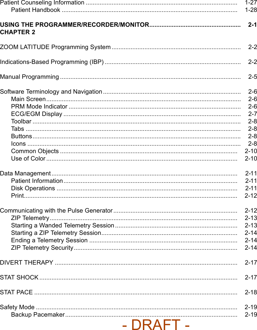
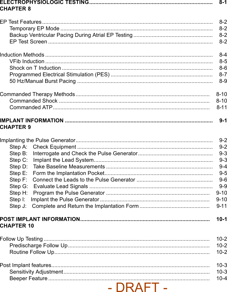
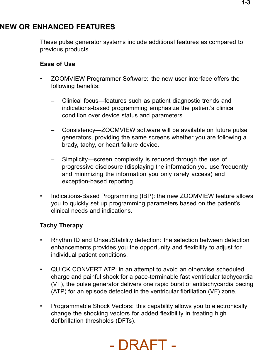
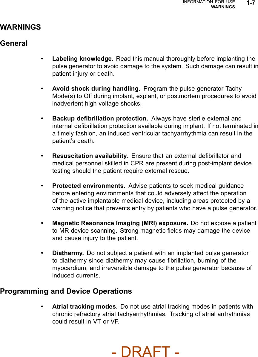
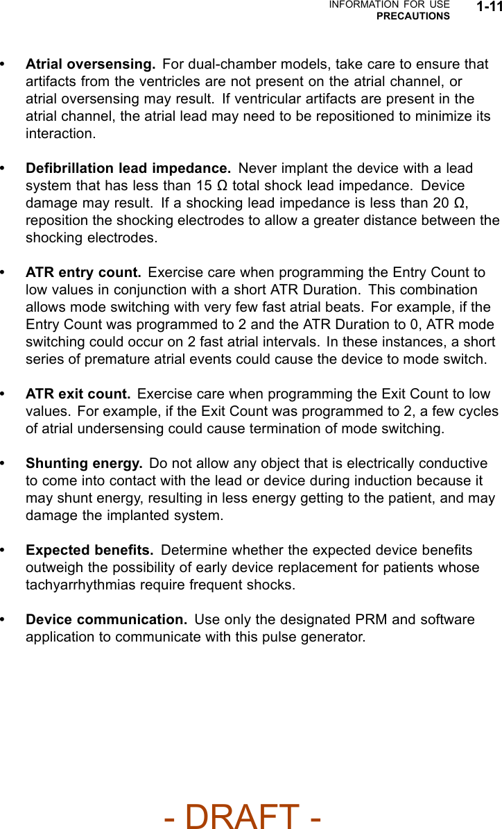
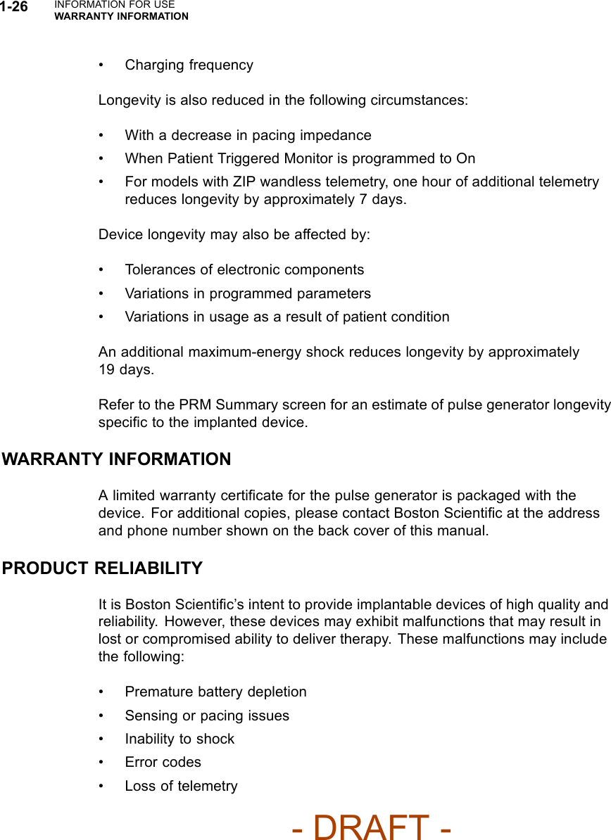
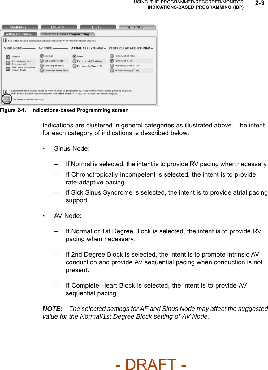
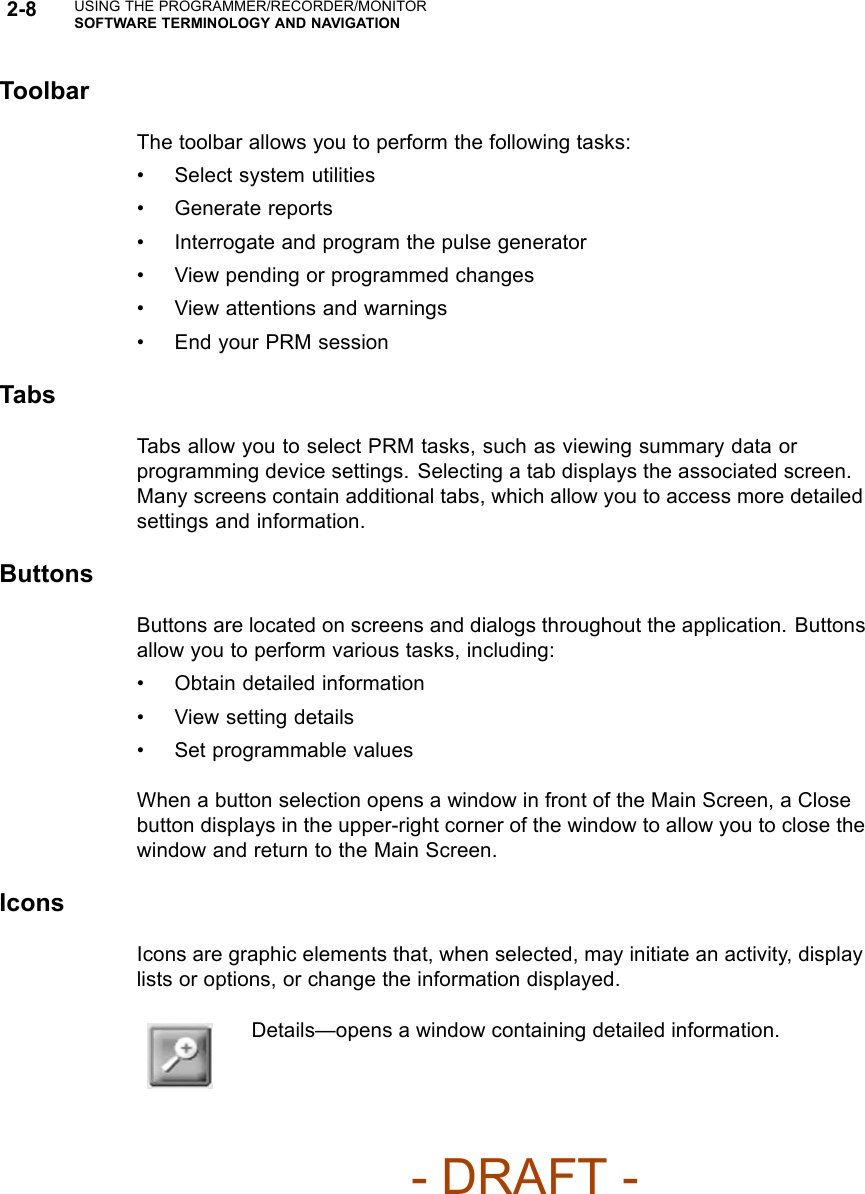
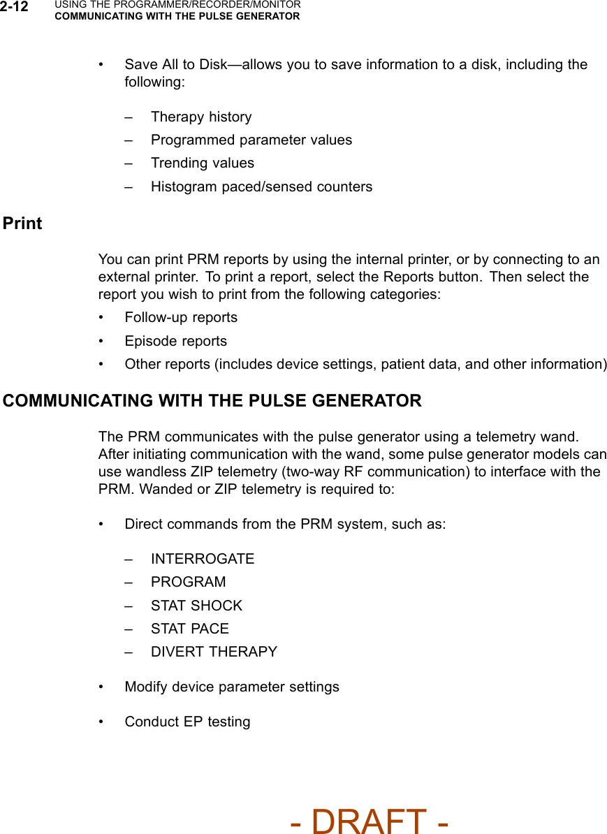
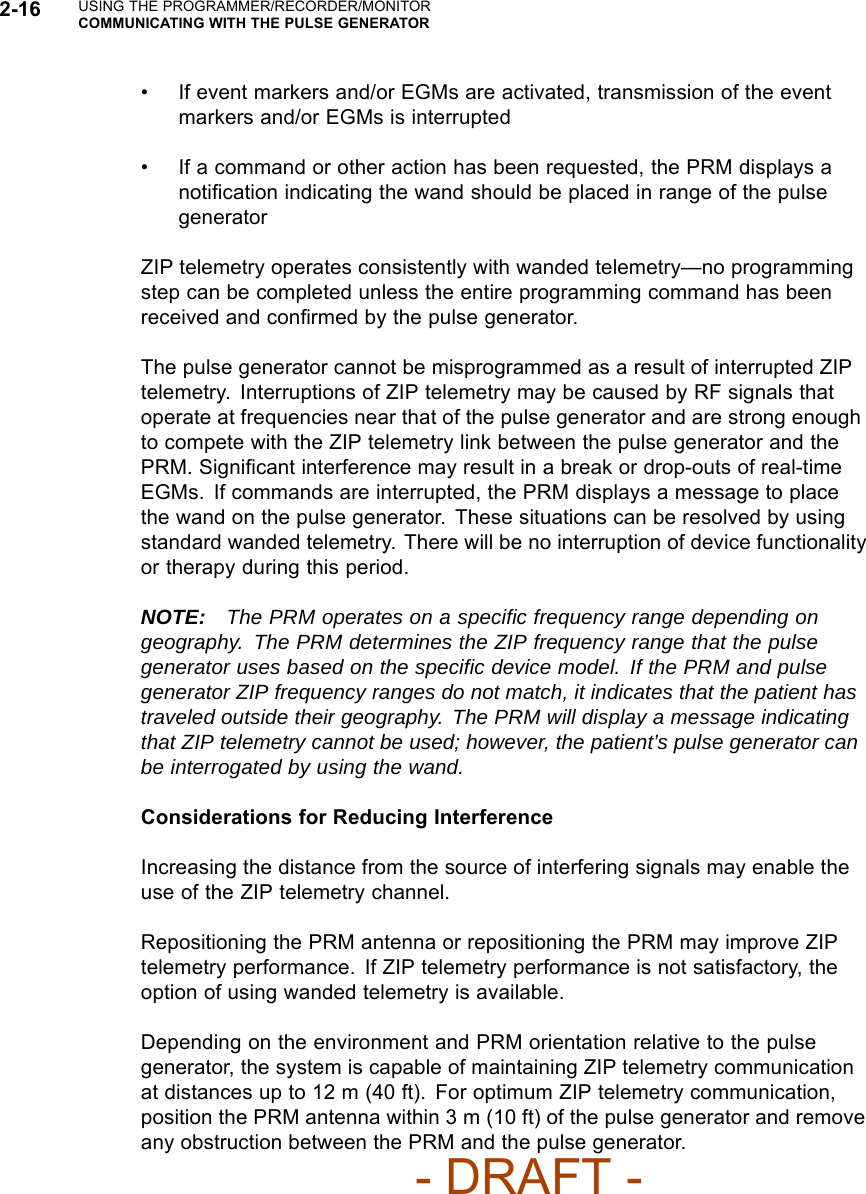
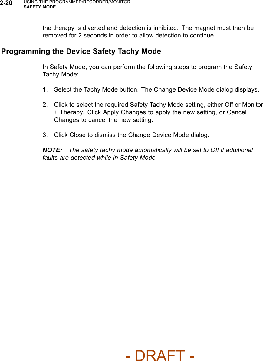
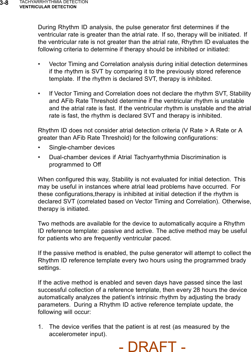
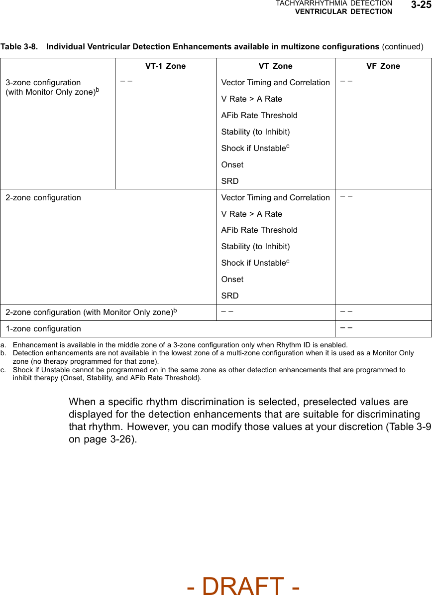
![PACING THERAPIESBASIC PARAMETERS 5-7Pacing without modified ventricular timing Pacing with modified ventricular timing 150 200 ms AV VA AV + VA Forced extension of the V-A interval 150 200 ms AV VA AV + VA + extension MSR 400 ms (150 min-1 [ppm])AV 150 ms (conducted event)V-A 200 msPacing interval = AV + VA = 350 msMSR 400 ms (150 min-1 [ppm])AV 150 msV-A Ext. 50 msVA 200 msPacing interval = AV + VA + VA extension = 400 msThe pulse generator’s timing algorithm provides effective pacing at the MSR with intrinsic ventricular conduction.Extending the VA interval prevents the A pace from exceeding the MSR at high rates.Figure 5-1. VA interval extension and MSRPulse WidthPulse Width, also referred to as pulse duration, determines how long the outputpulse will be applied between the pacing electrodes.The following considerations are important when programming Pulse Width:• Pulse widths are independently programmable.• The energy delivered to the heart is directly proportional to the pulse width.Therefore, programming a shorter pulse width increases pulse generatorlongevity. To prevent loss of capture, exercise caution when you areprogramming permanent pulse width values of less than 0.3 ms (Figure 5-2on page 5-8).- DRAFT -](https://usermanual.wiki/Boston-Scientific/CRMN11906.Teligen-Part-1-Manual/User-Guide-886100-Page-139.png)