Cambium Networks 50450M 5GHz Point to MultiPoint Multi User MIMO Access Point User Manual USERS MANUAL PART3
Cambium Networks Limited 5GHz Point to MultiPoint Multi User MIMO Access Point USERS MANUAL PART3
Contents
- 1. USER GUIDE P1
- 2. USER GUIDE P2
- 3. USER GUIDE P3
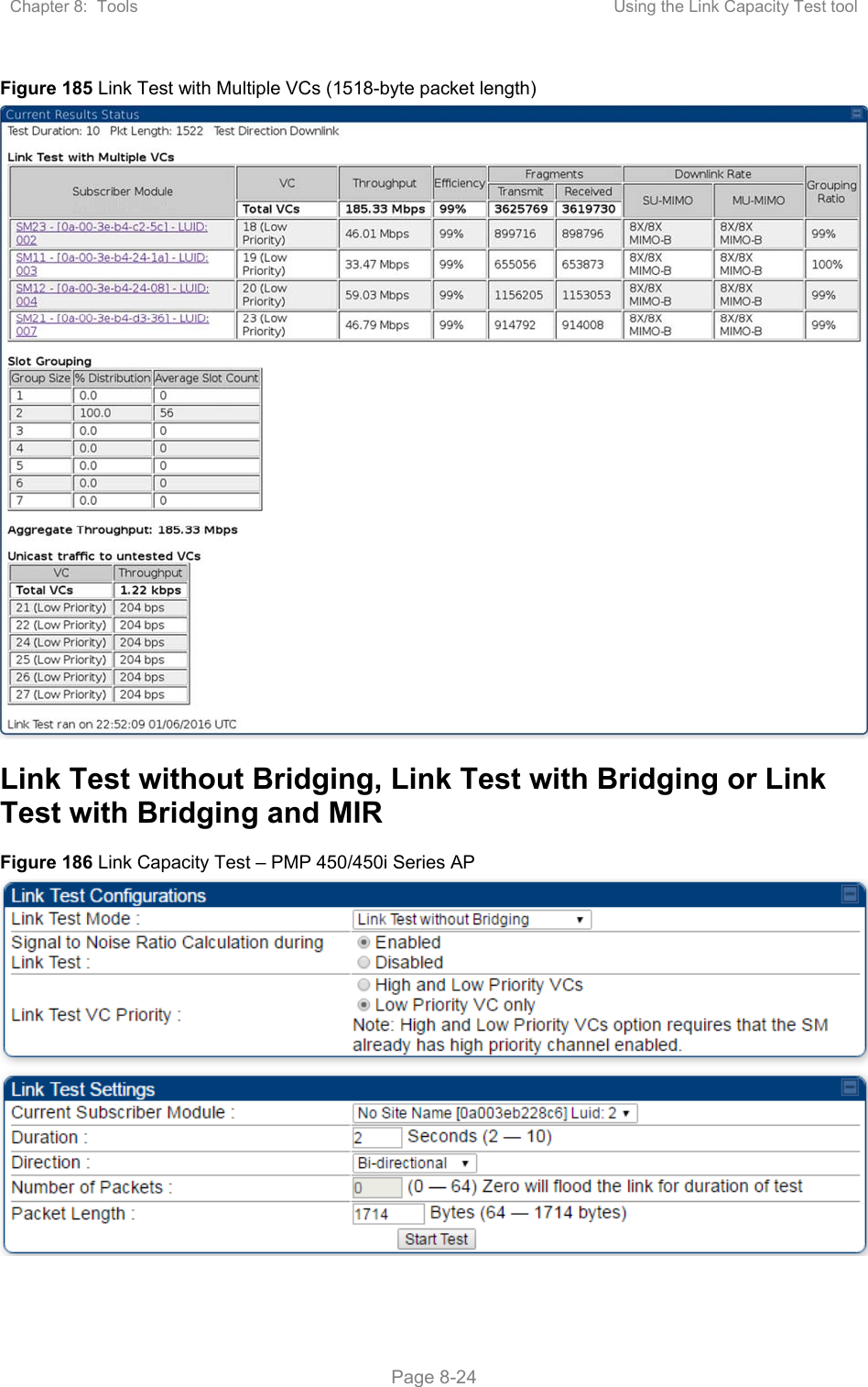
- 4. USER GUIDE P4
- 5. User manual
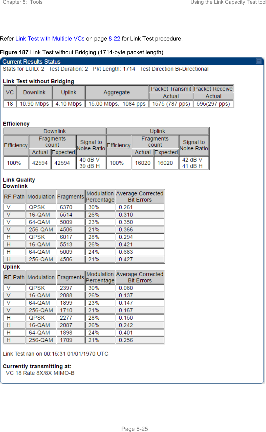
- 6. User Manual
- 7. USERS MANUAL PART1
- 8. USERS MANUAL PART2
- 9. USERS MANUAL PART3
- 10. USERS MANUAL PART4
- 11. USER MANUAL PART1
- 12. USER MANUAL PART2
- 13. USER MANUAL PART 3
- 14. USER MANUAL PART 4
- 15. USER MANUAL PT1
- 16. USER MANUAL PT2
- 17. USER MANUAL PT3
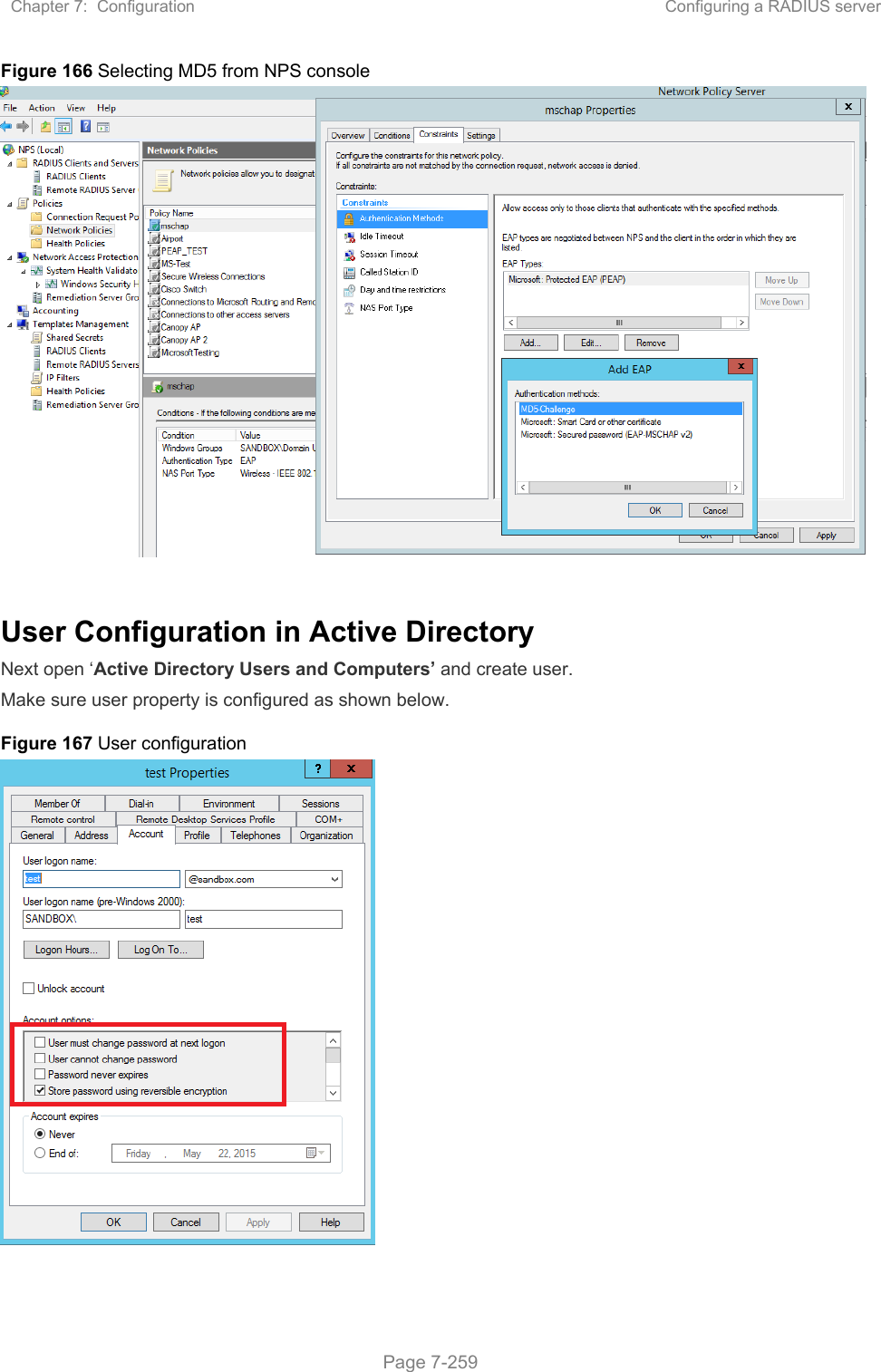
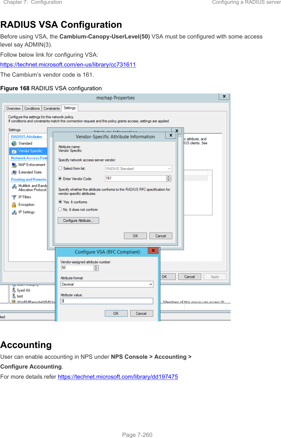
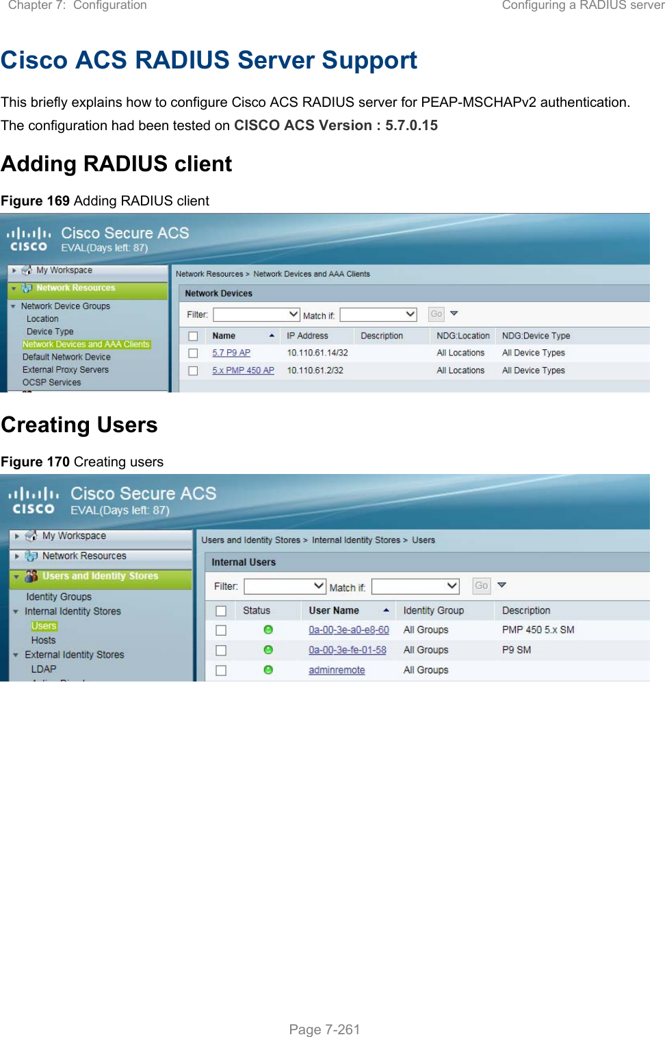
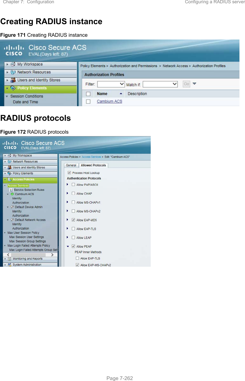
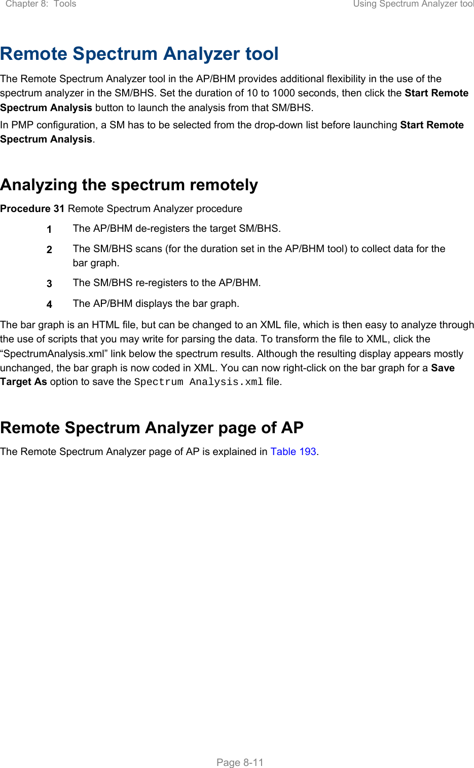
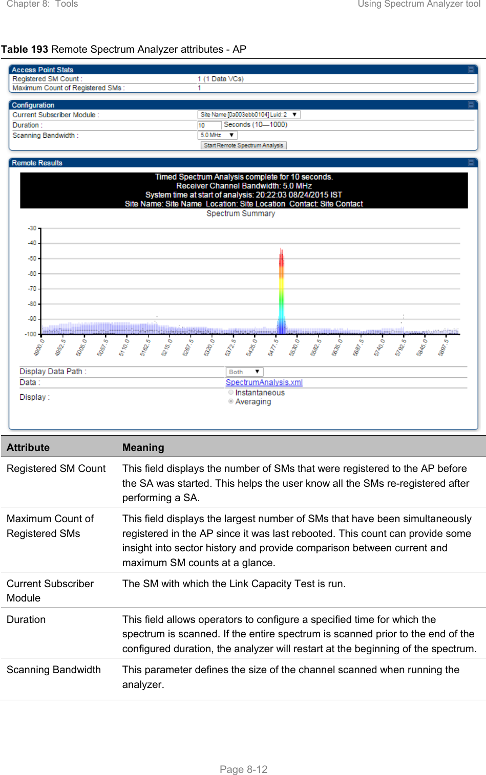
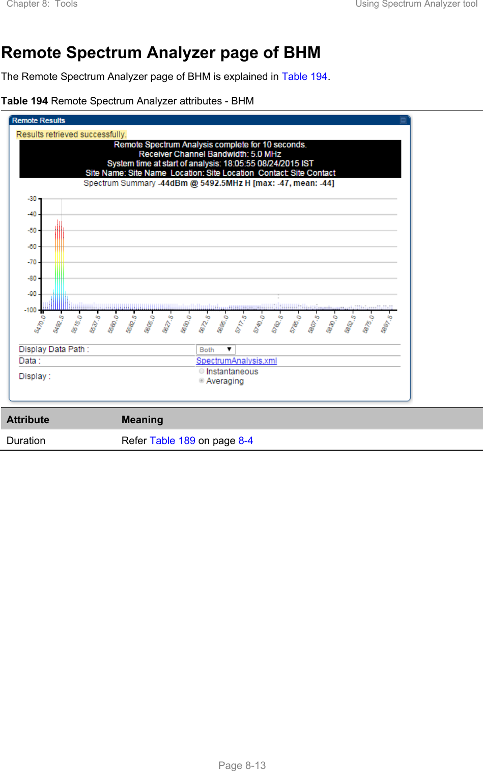
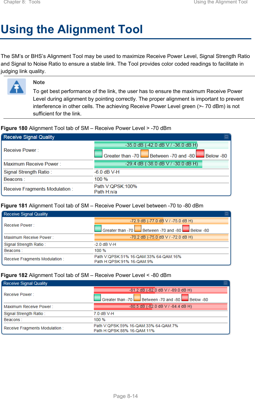
USERS MANUAL PART3
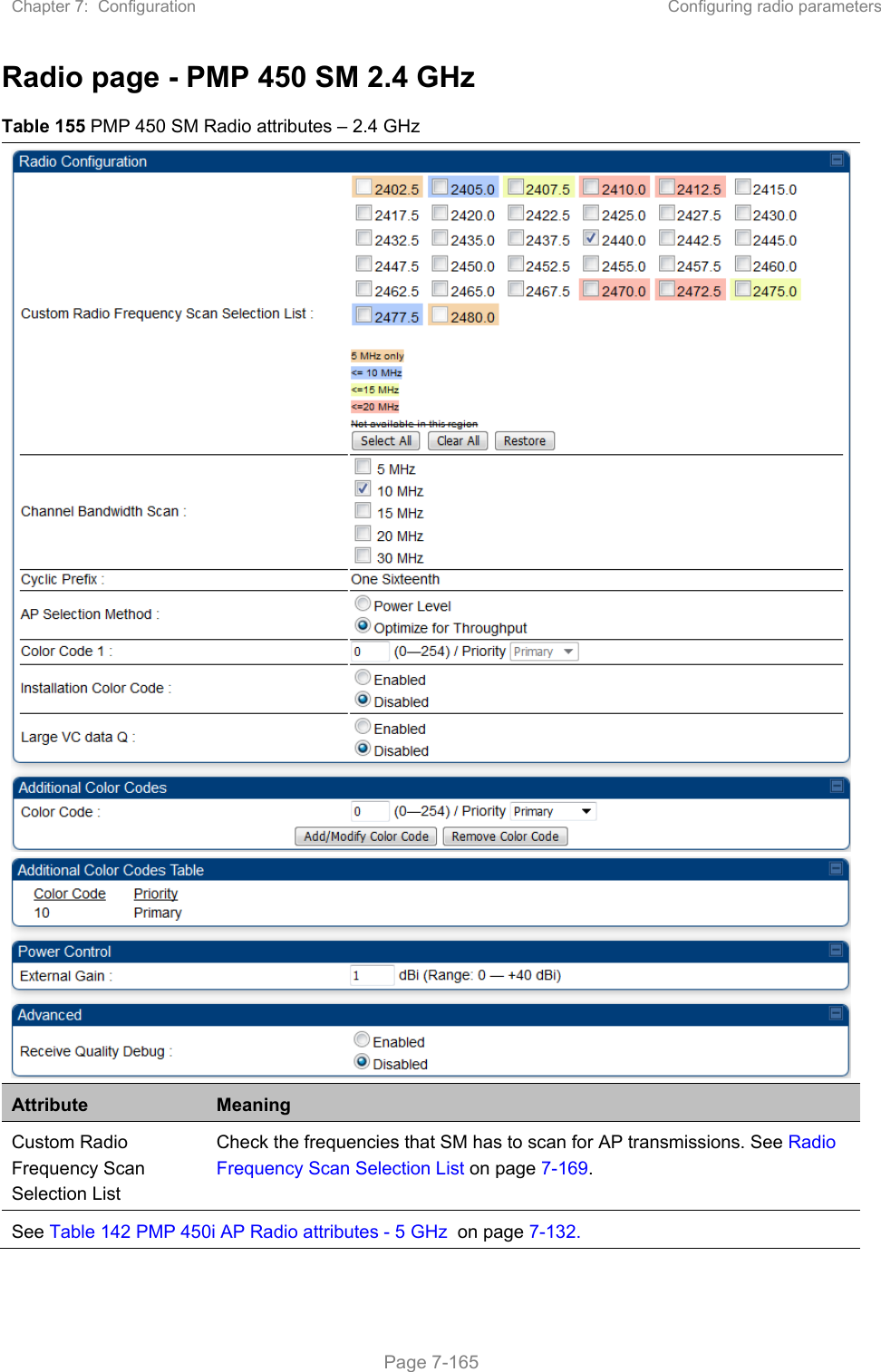
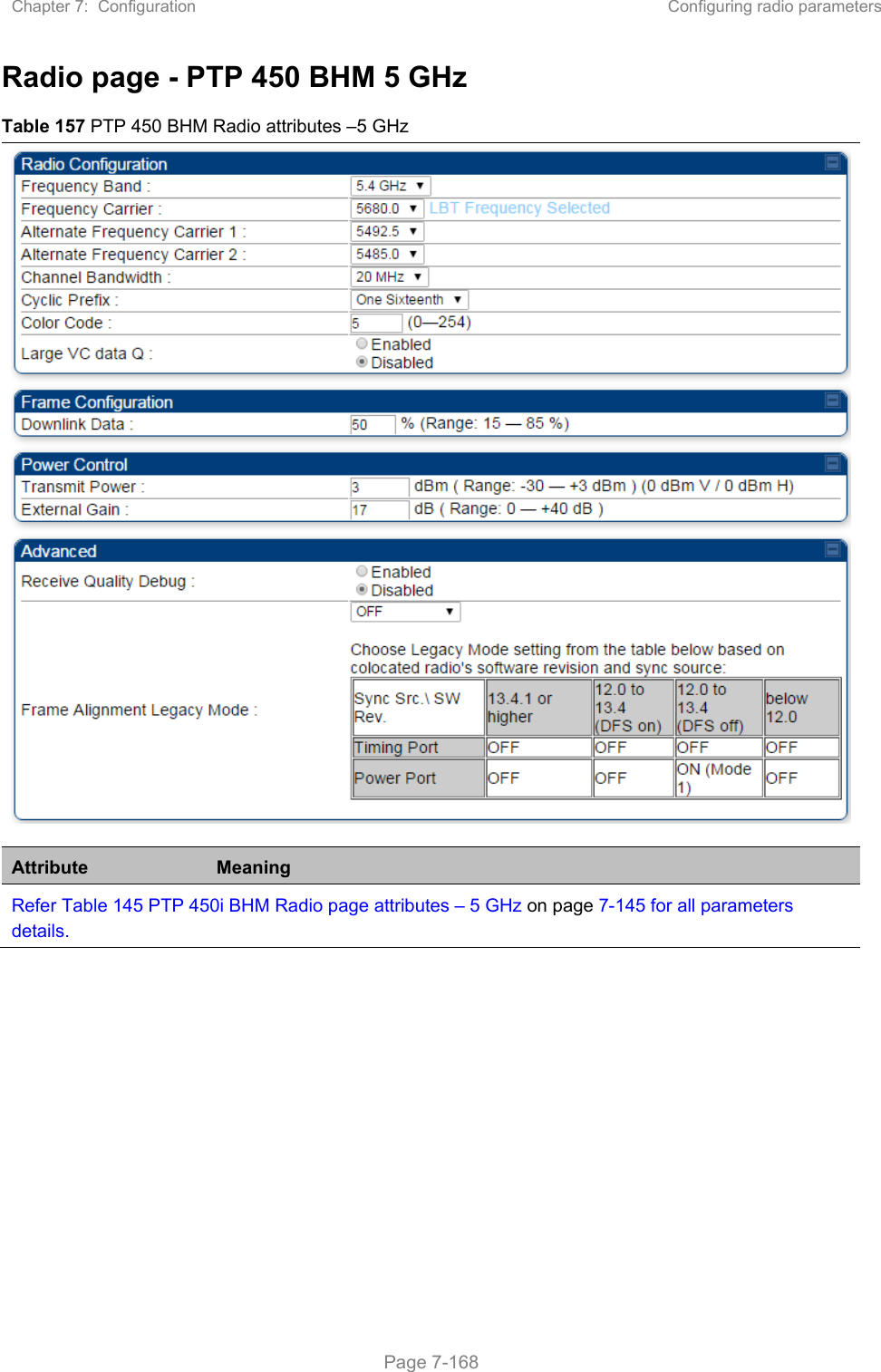
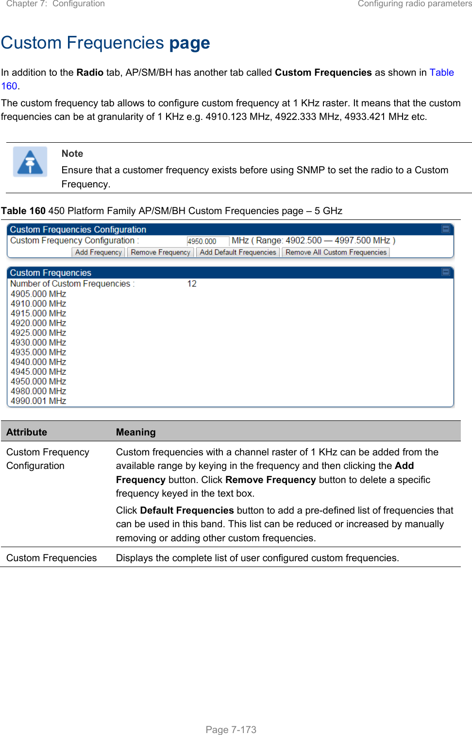
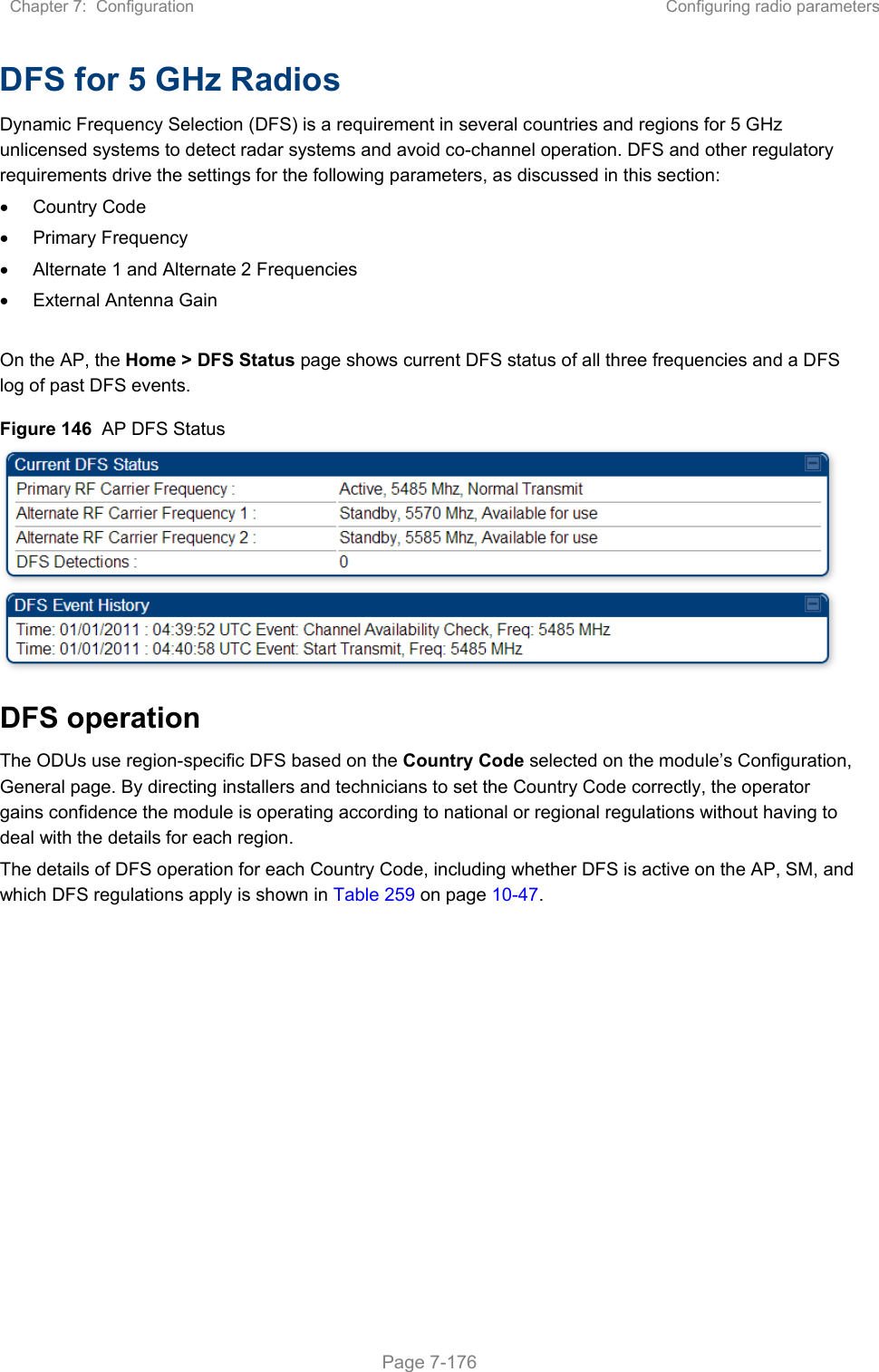
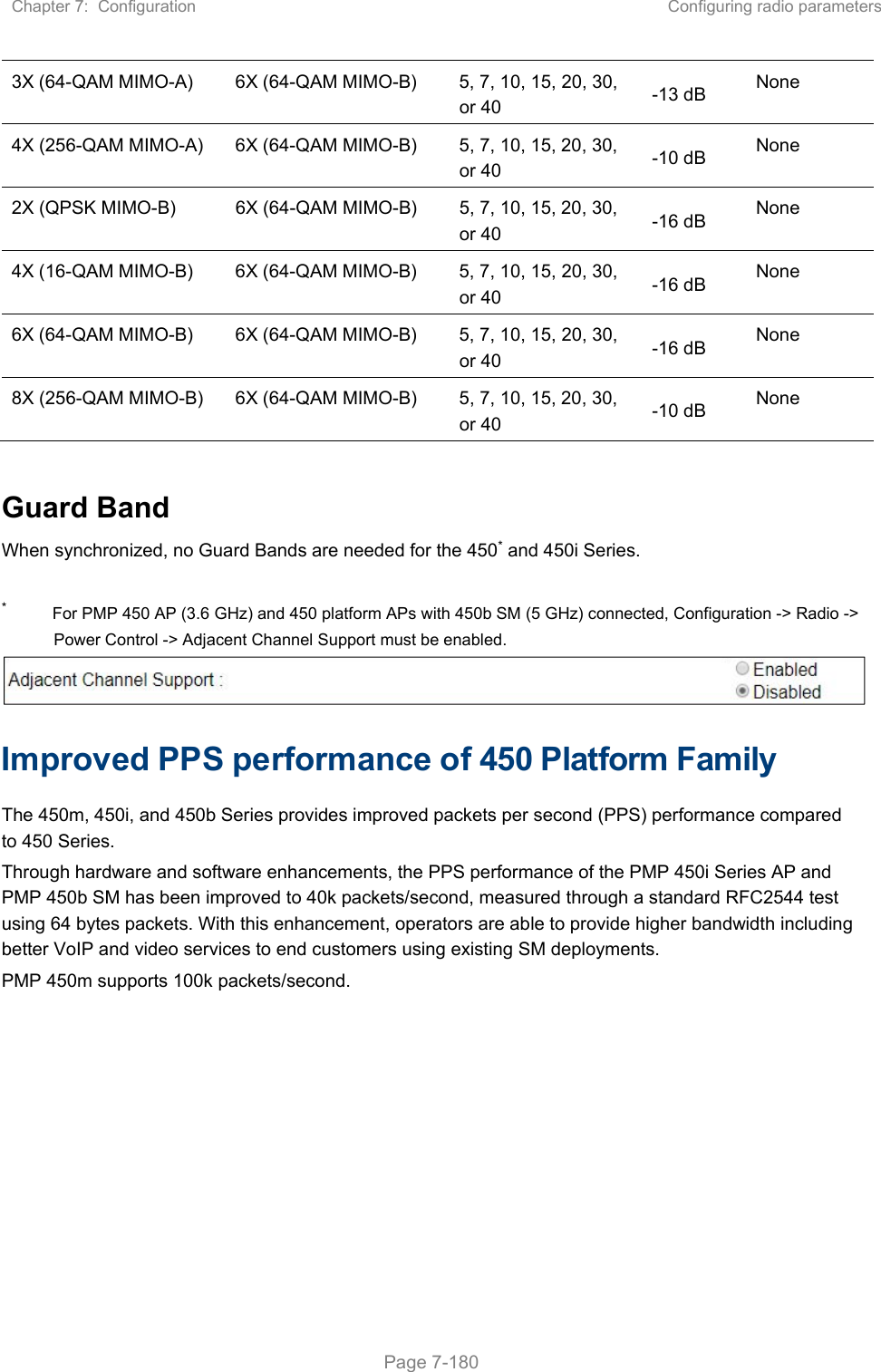
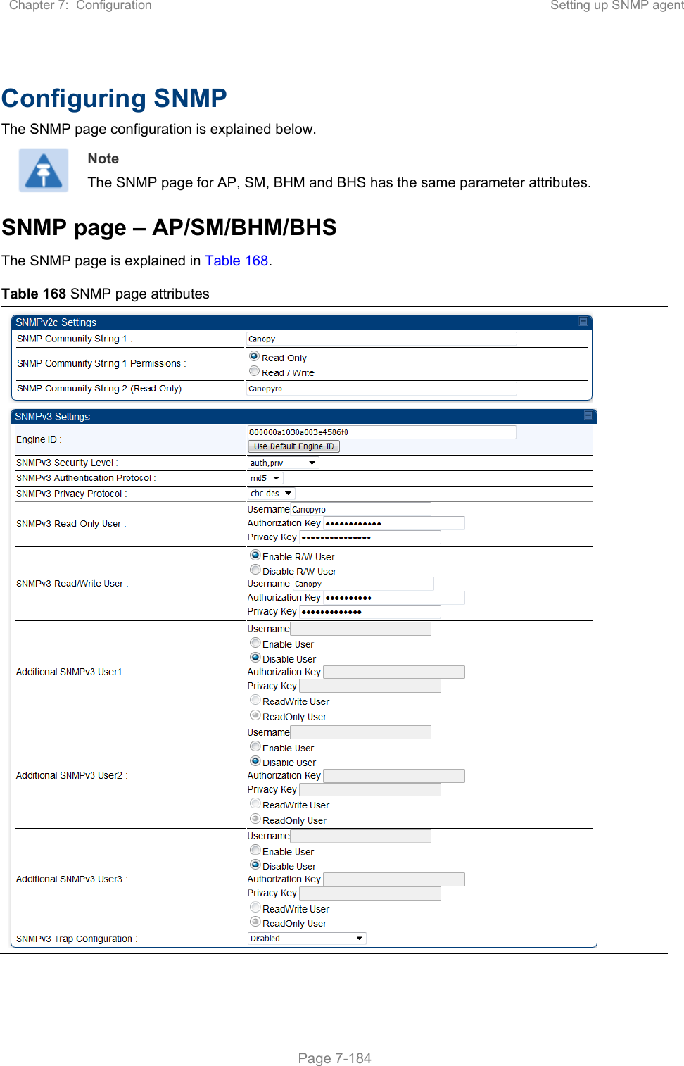
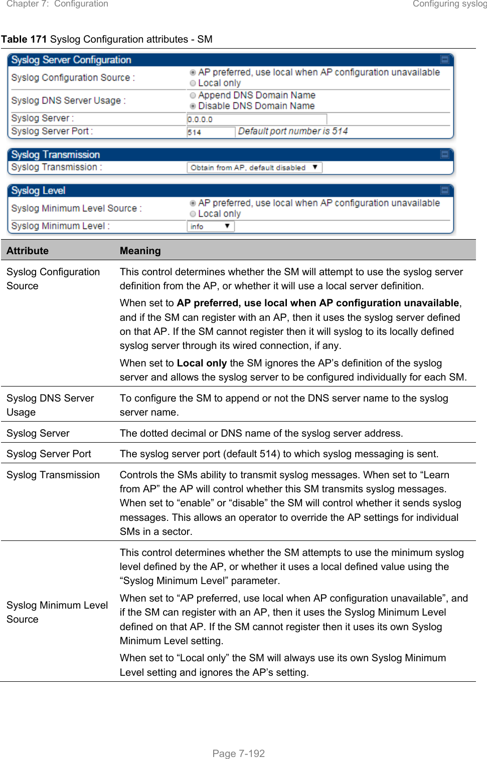
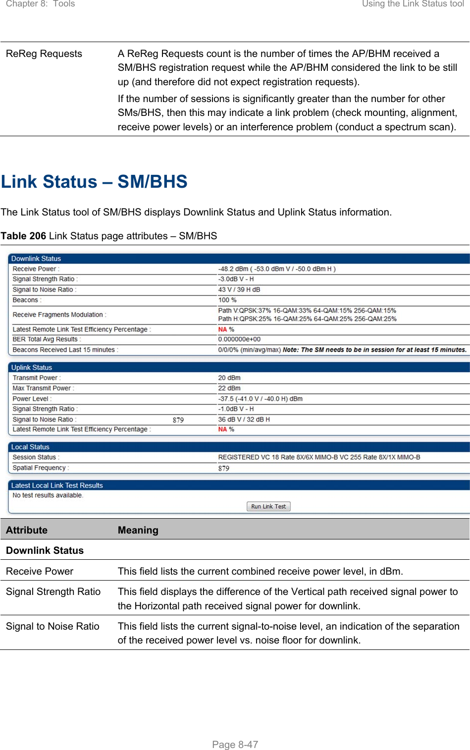
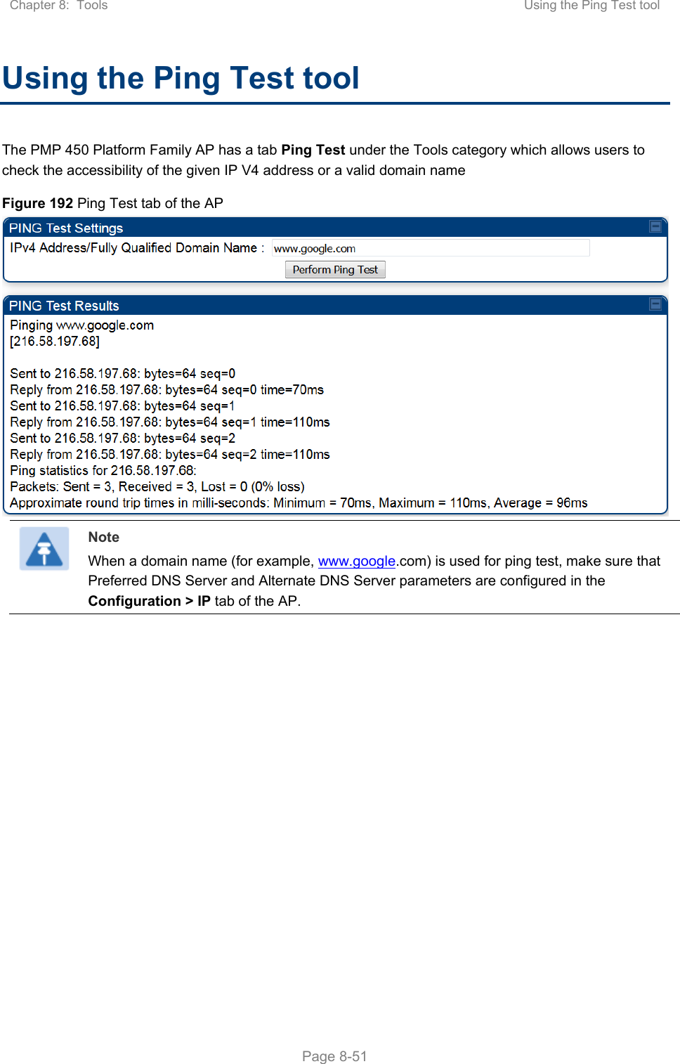
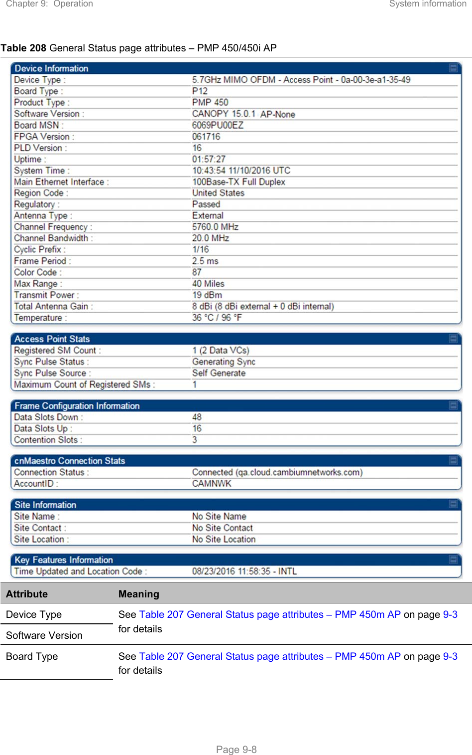
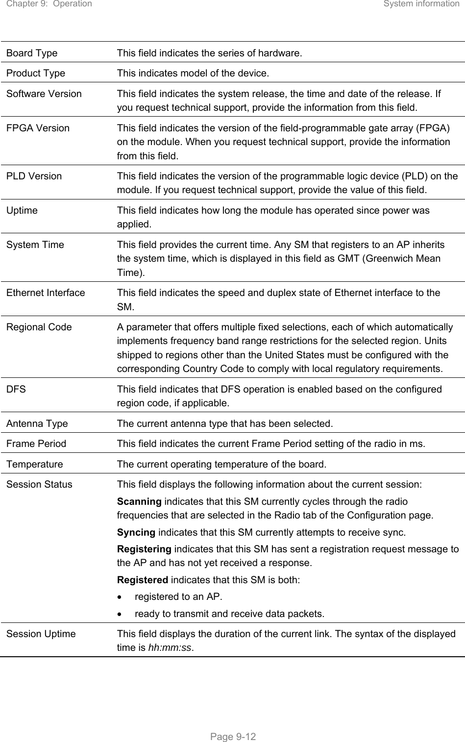
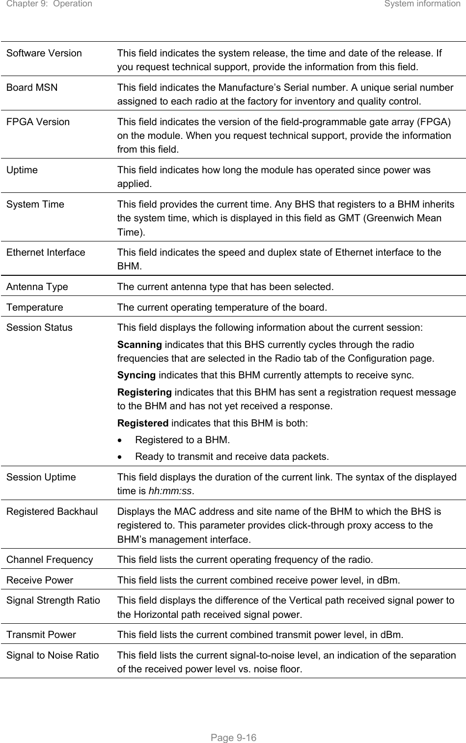
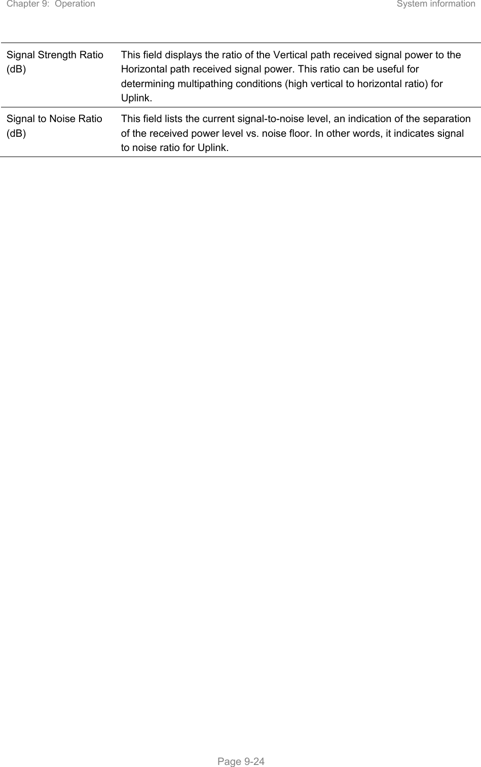
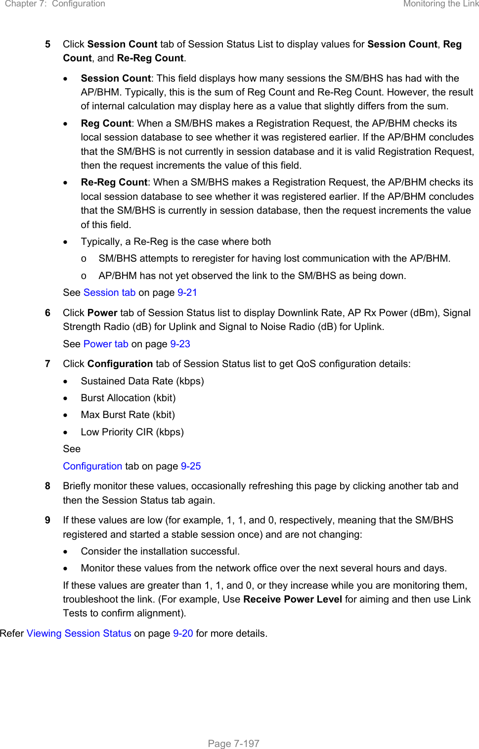
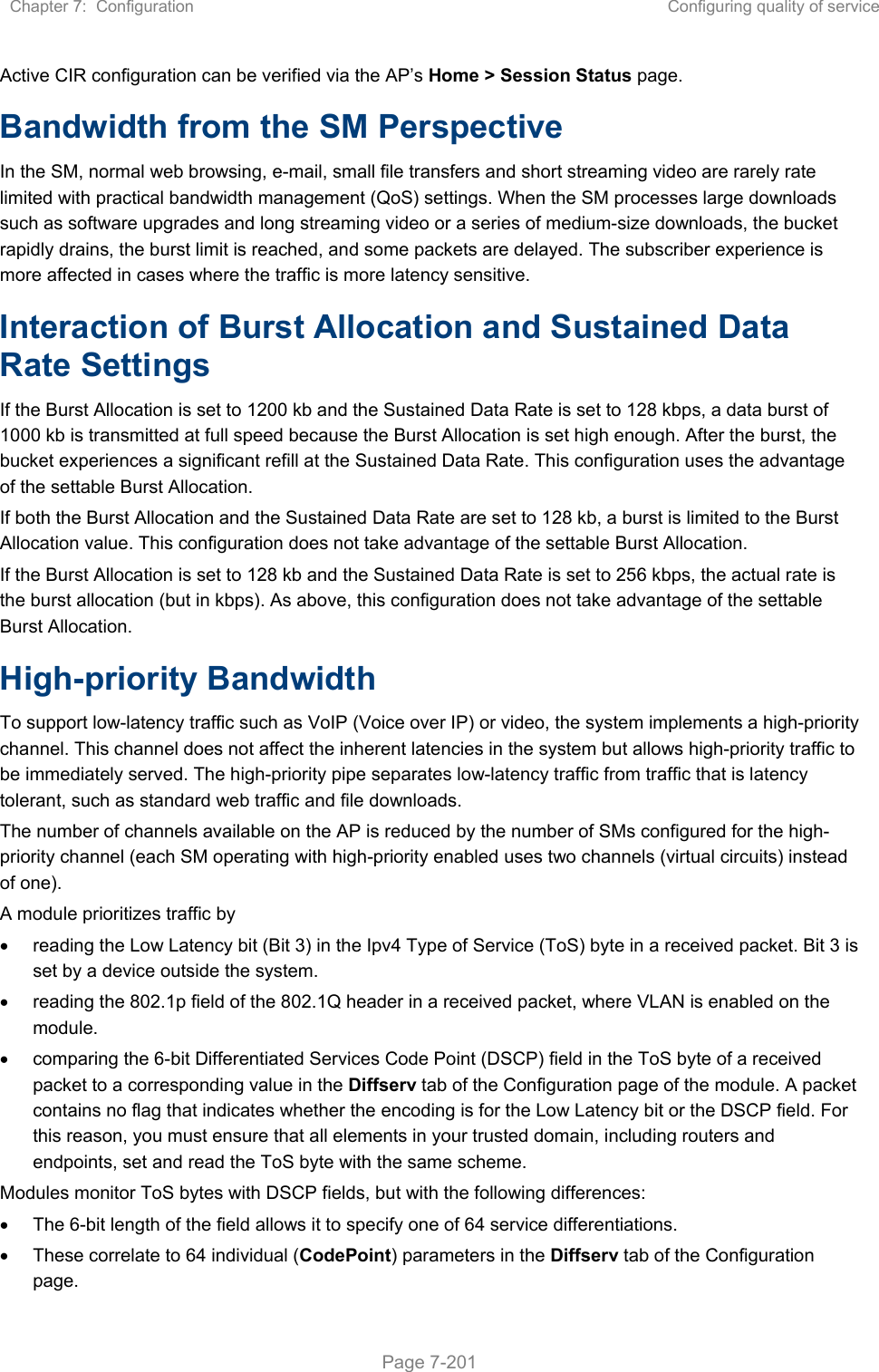
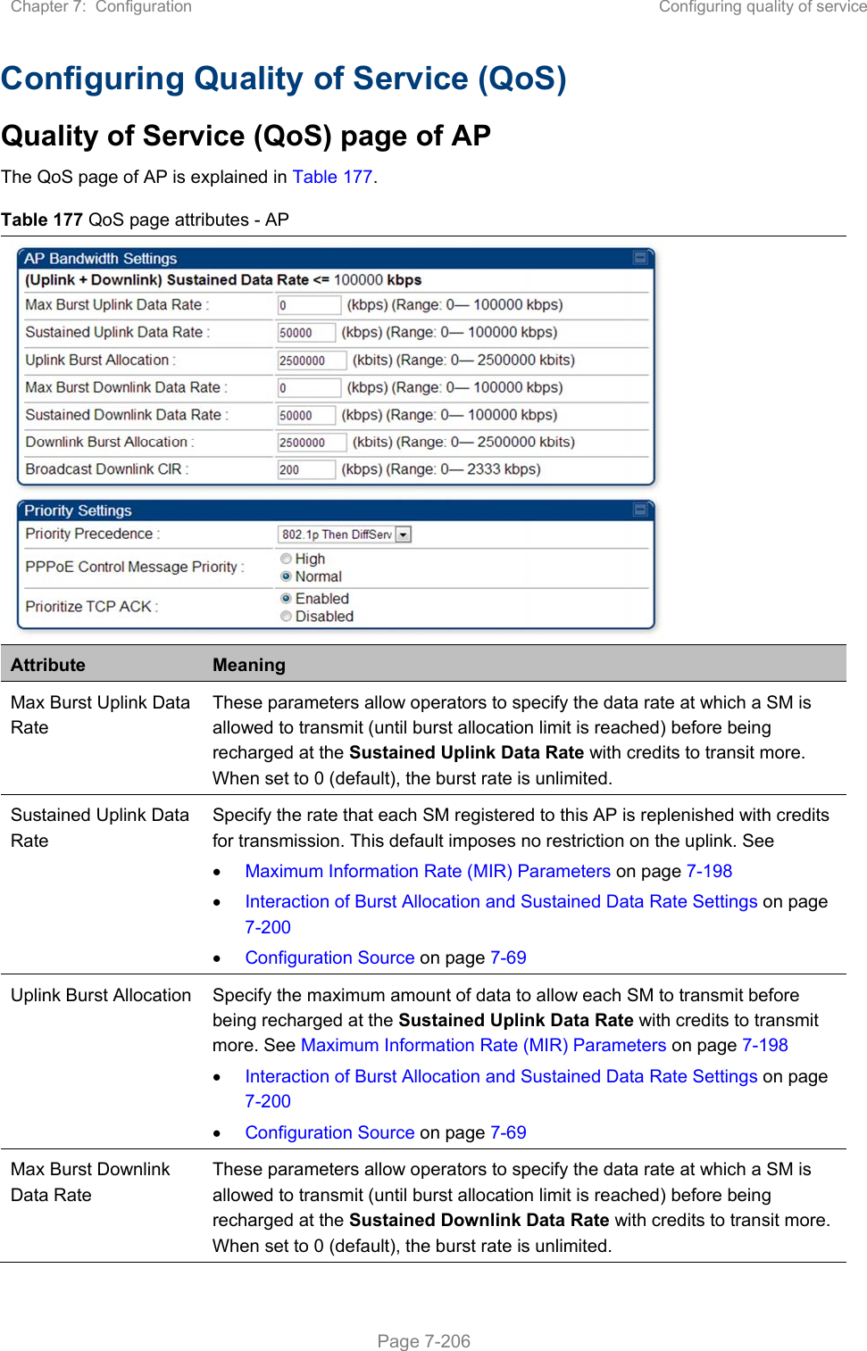
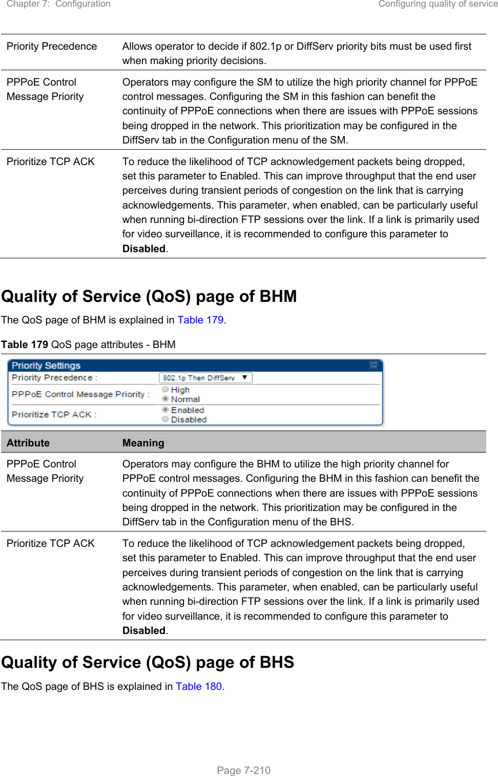
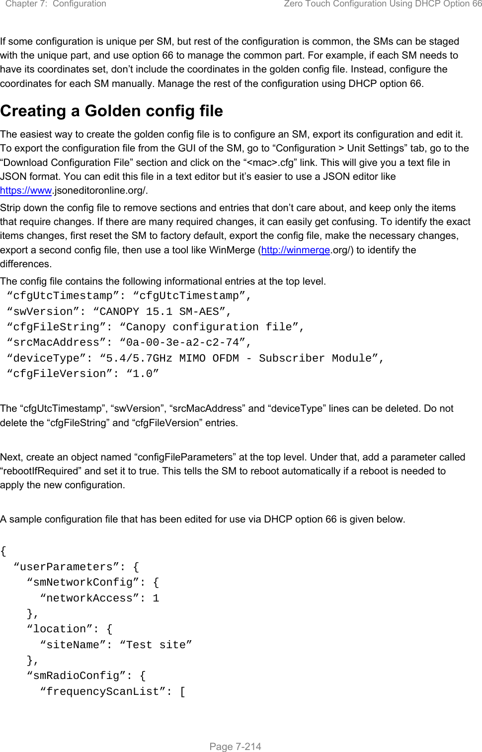
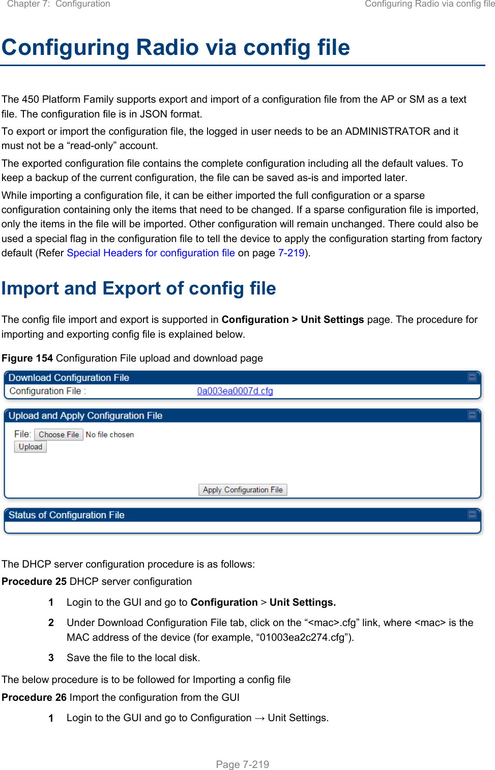
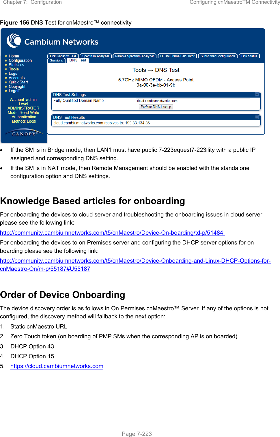
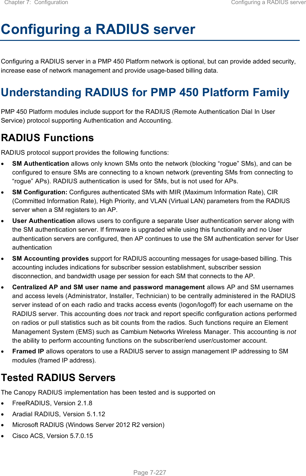
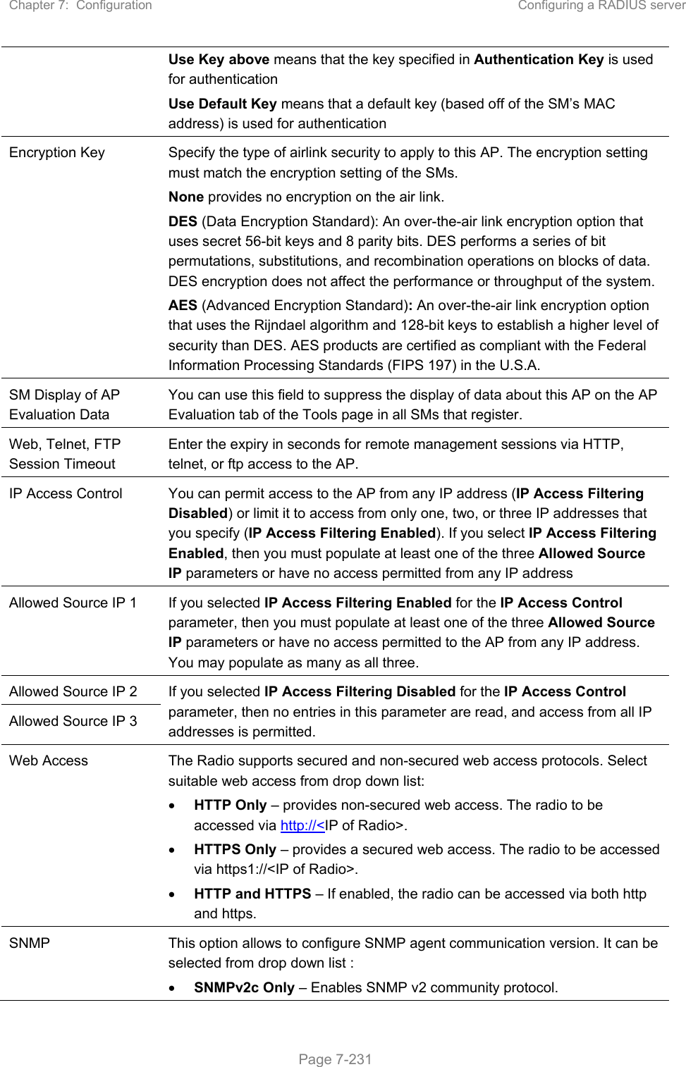
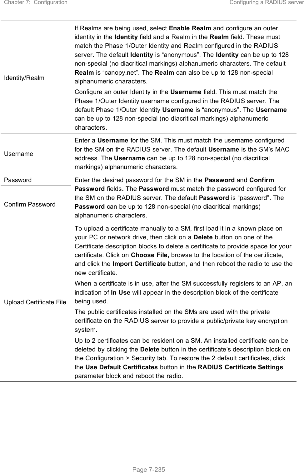
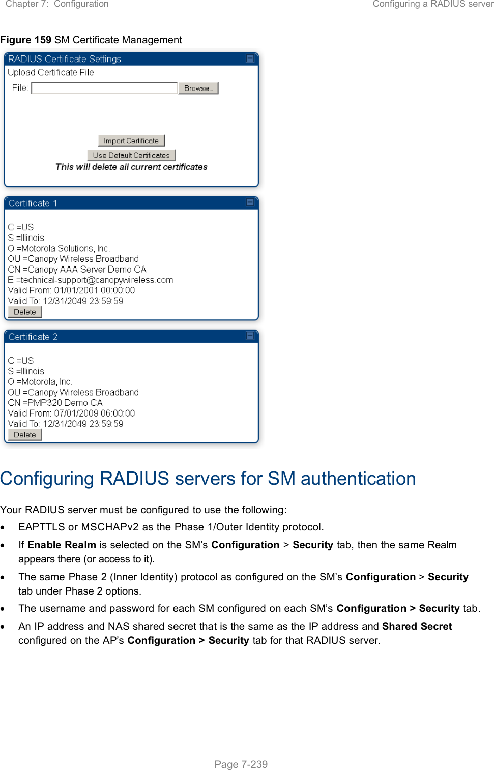
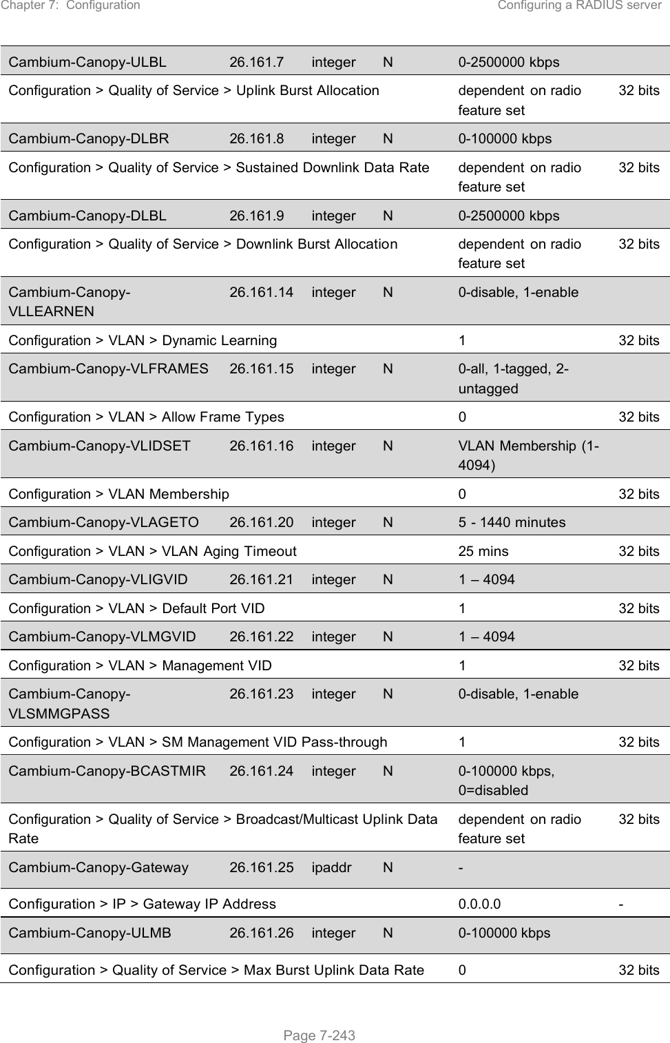
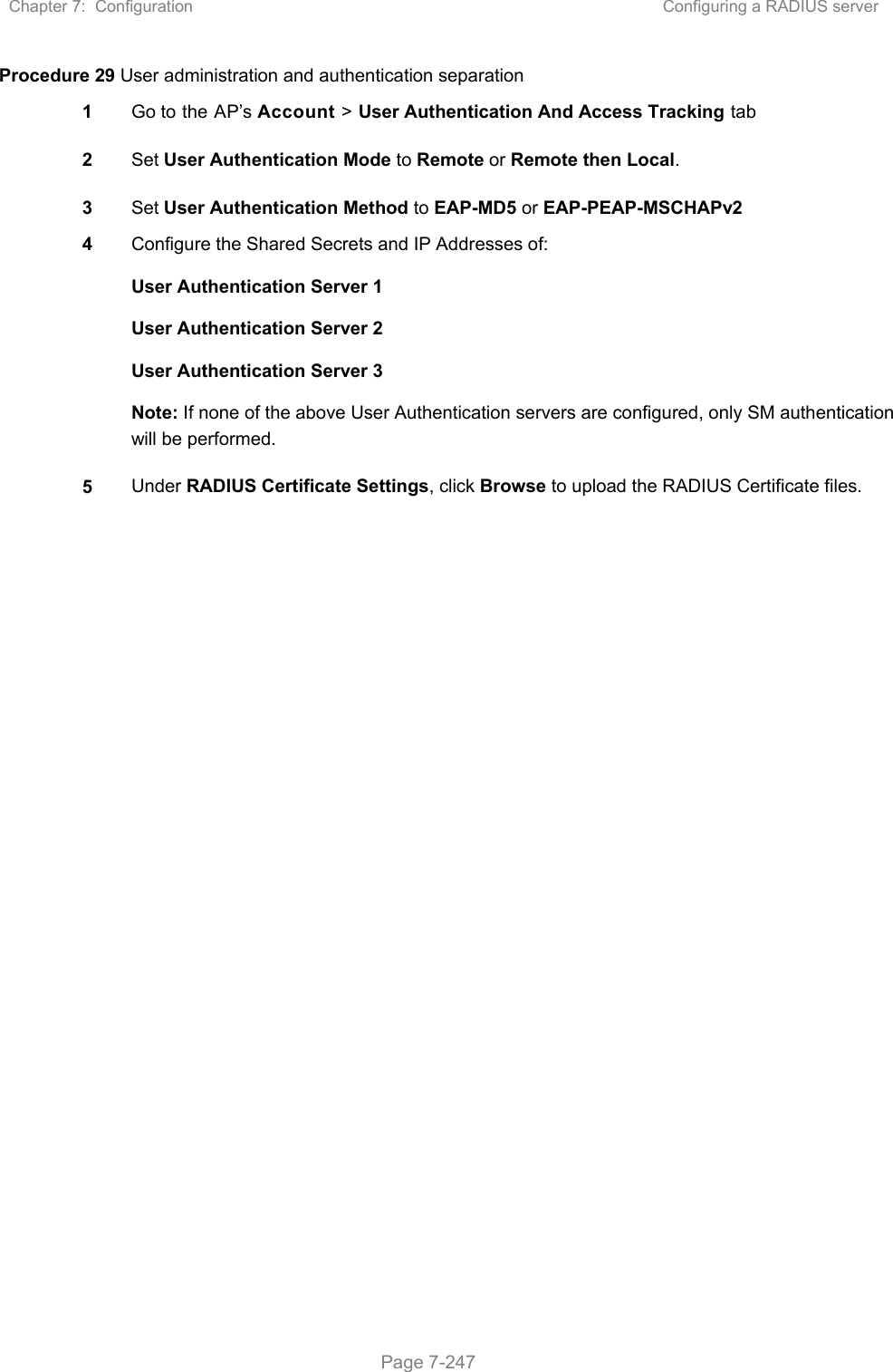
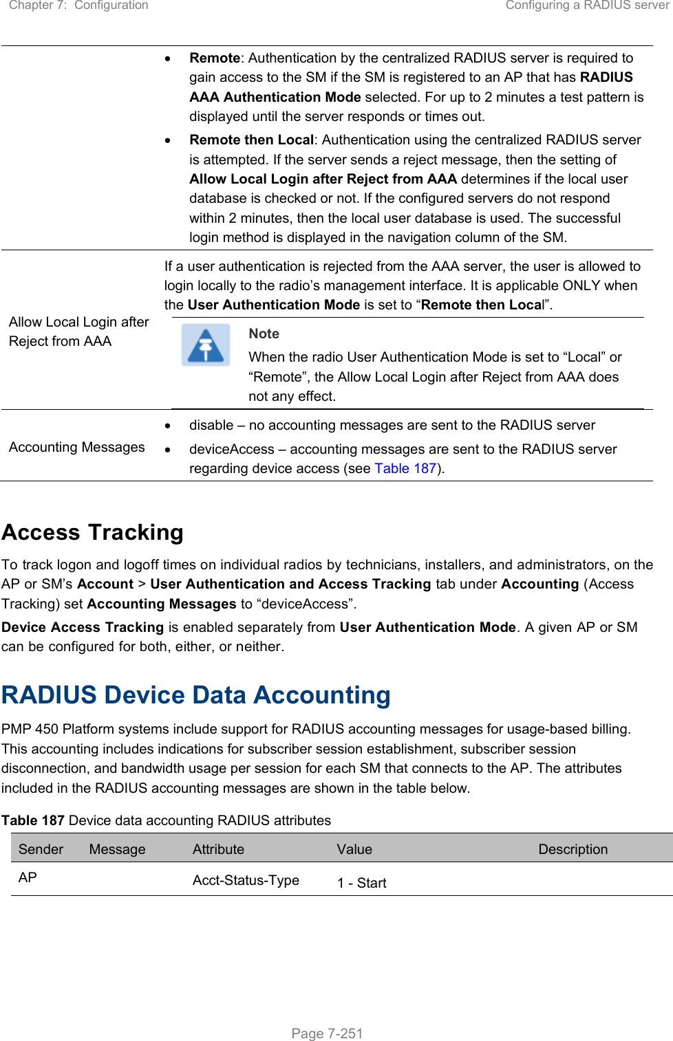
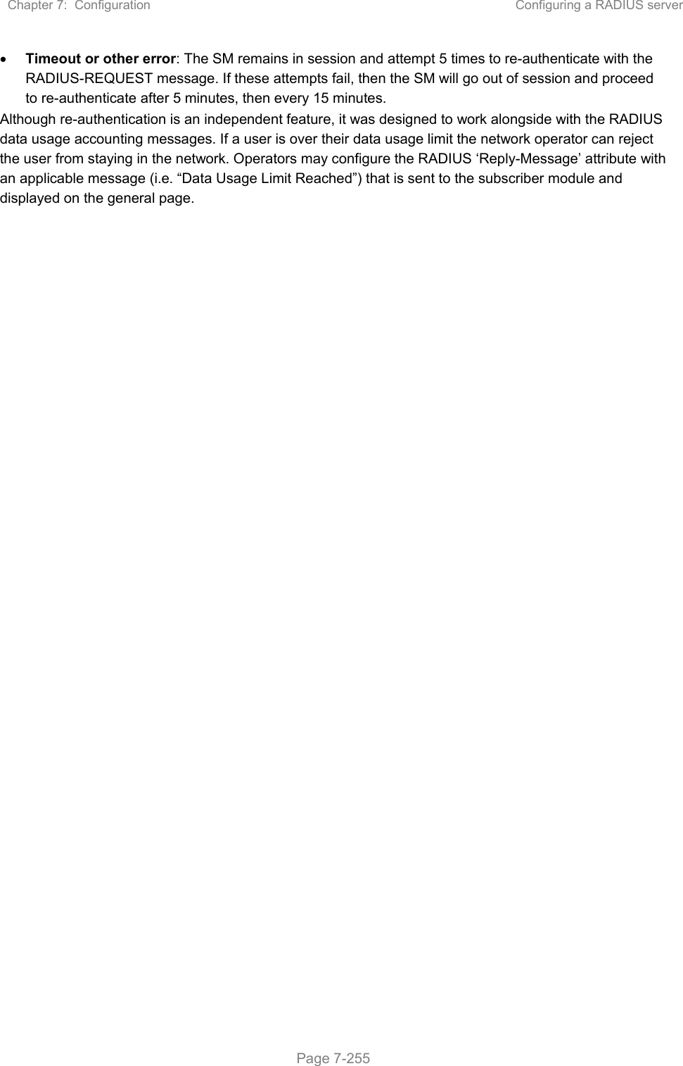
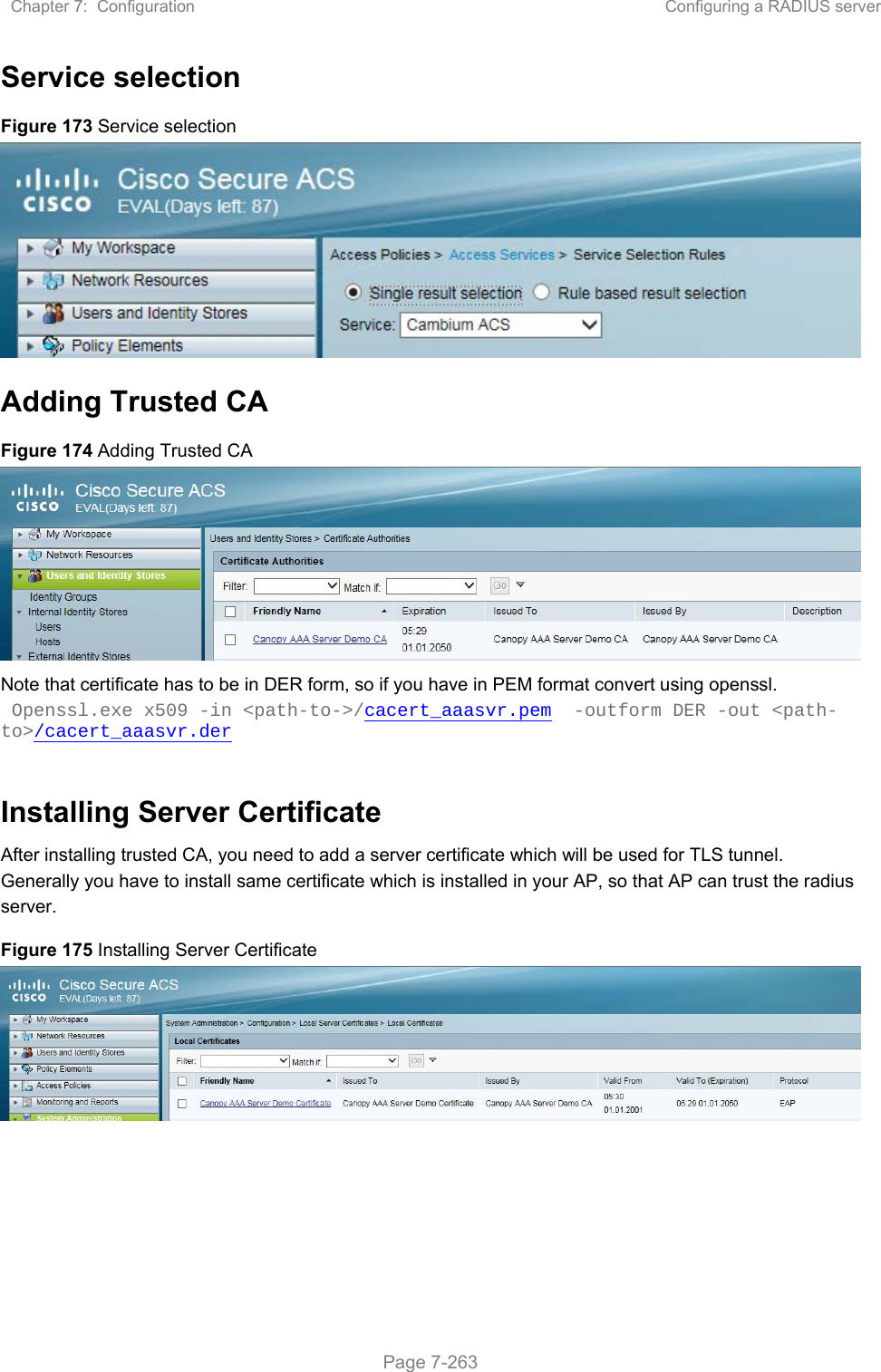
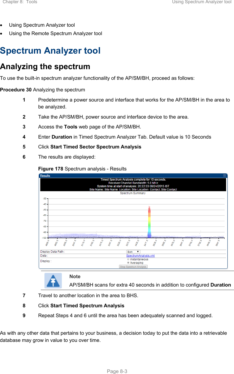
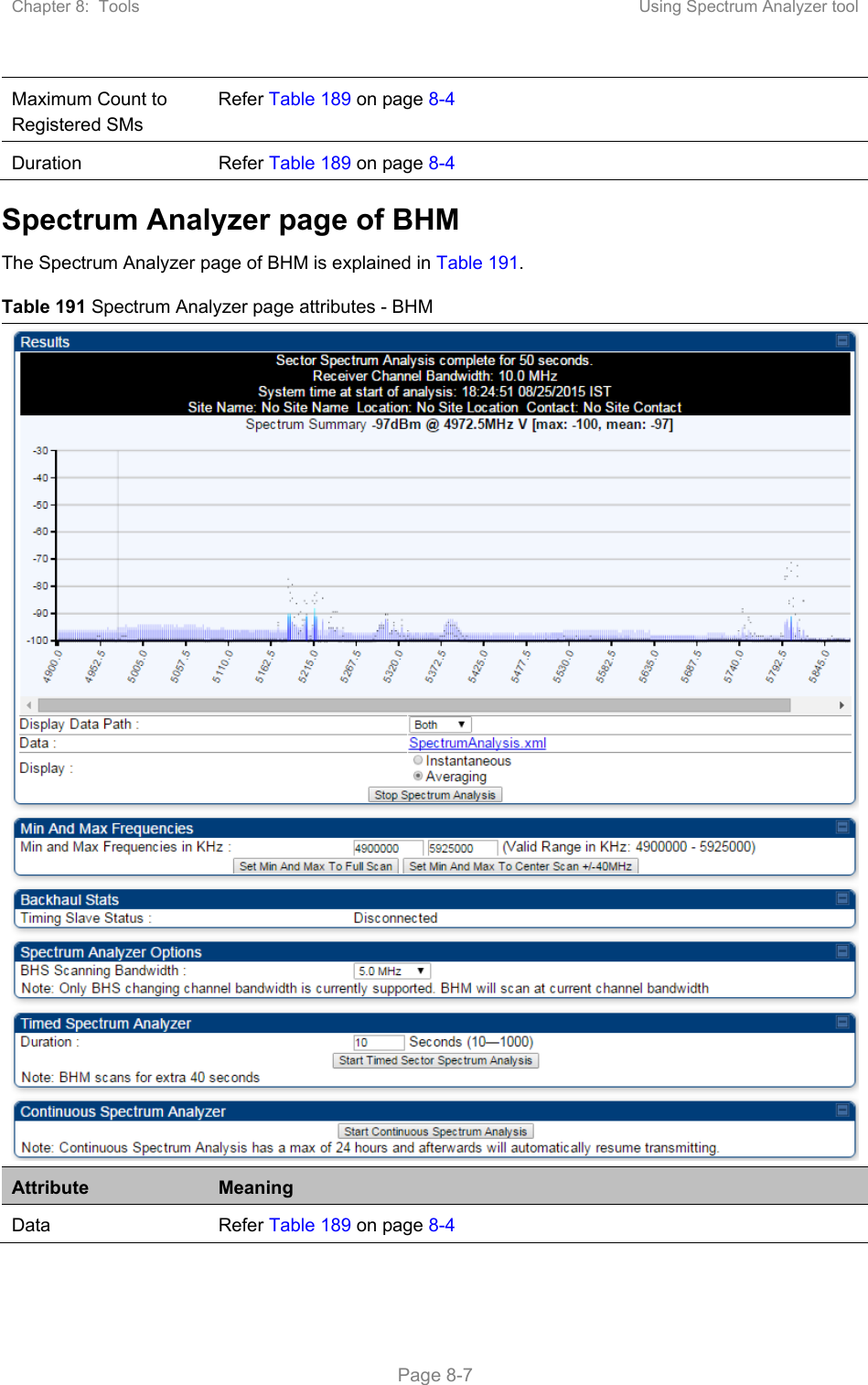
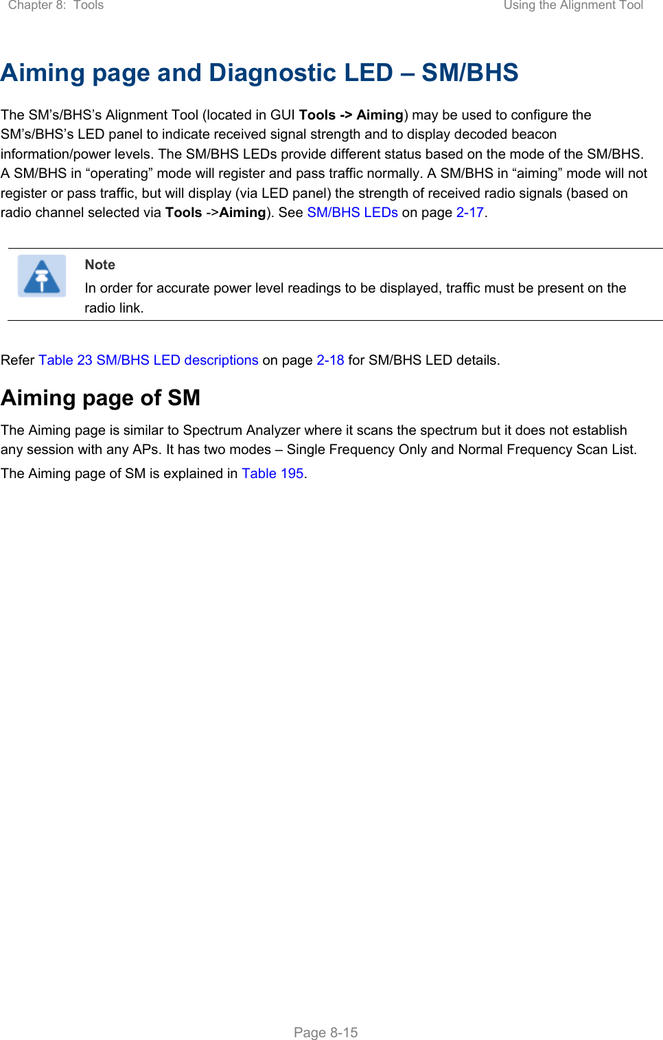
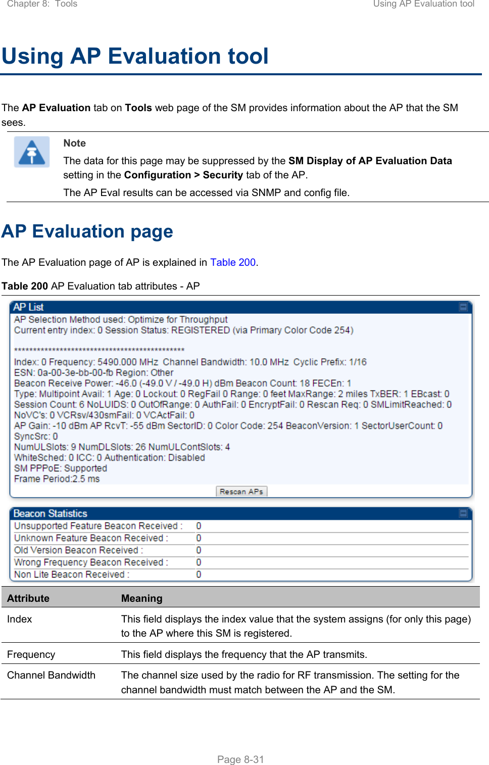
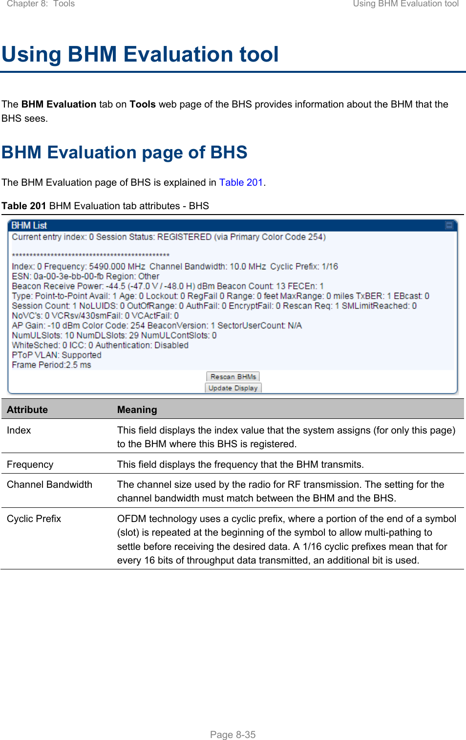
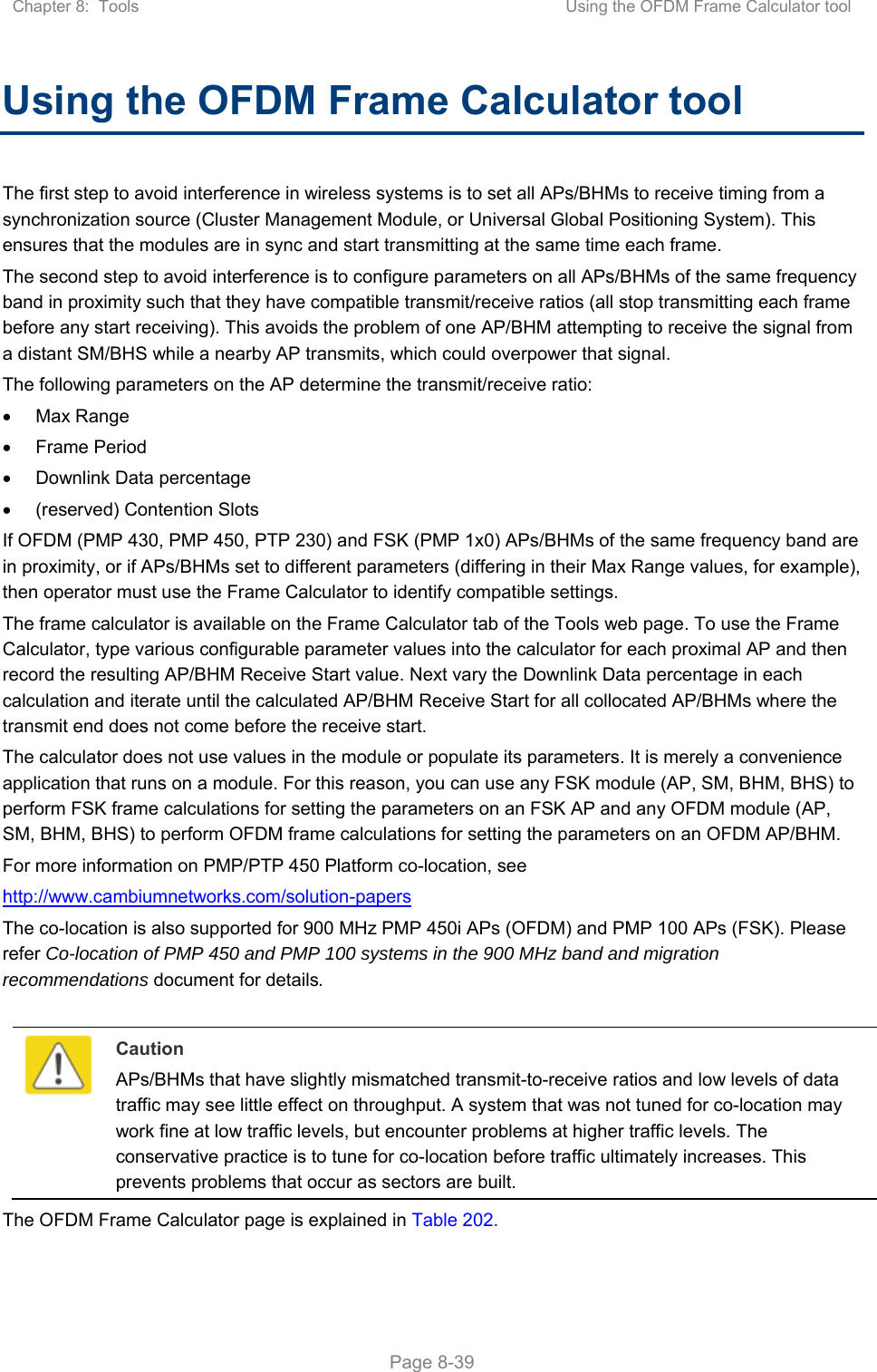
![Chapter 7: Configuration Configuring remote access Page 7-195 Configuring remote access Accessing SM/BHS over-the-air by Web Proxy The SM/BHS may be accessed via the AP/BHM management GUI by navigating to Home > Session Status (or Home > Remote Subscribers for AP only) and clicking on the SM’s hyperlink. For example, to access one of the SMs, click LUID: 002 – [0a-00-3e-37-b9-fd], as shown in Figure 147. Figure 147 AP Session Status page The SessionStatus.xml hyper link allows user to export all displayed SM data in Session Status table into an xml file. To access any one of the SMs, click 450 Platform Family - SM hyperlink, as shown in Figure 148. Figure 148 AP Remote Subscribers page](https://usermanual.wiki/Cambium-Networks/50450M.USERS-MANUAL-PART3/User-Guide-3650908-Page-32.png)
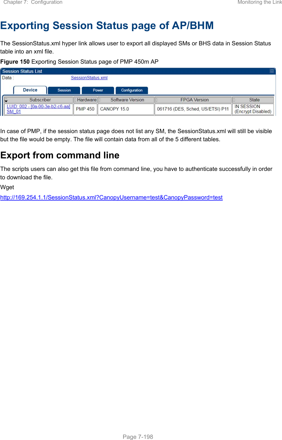
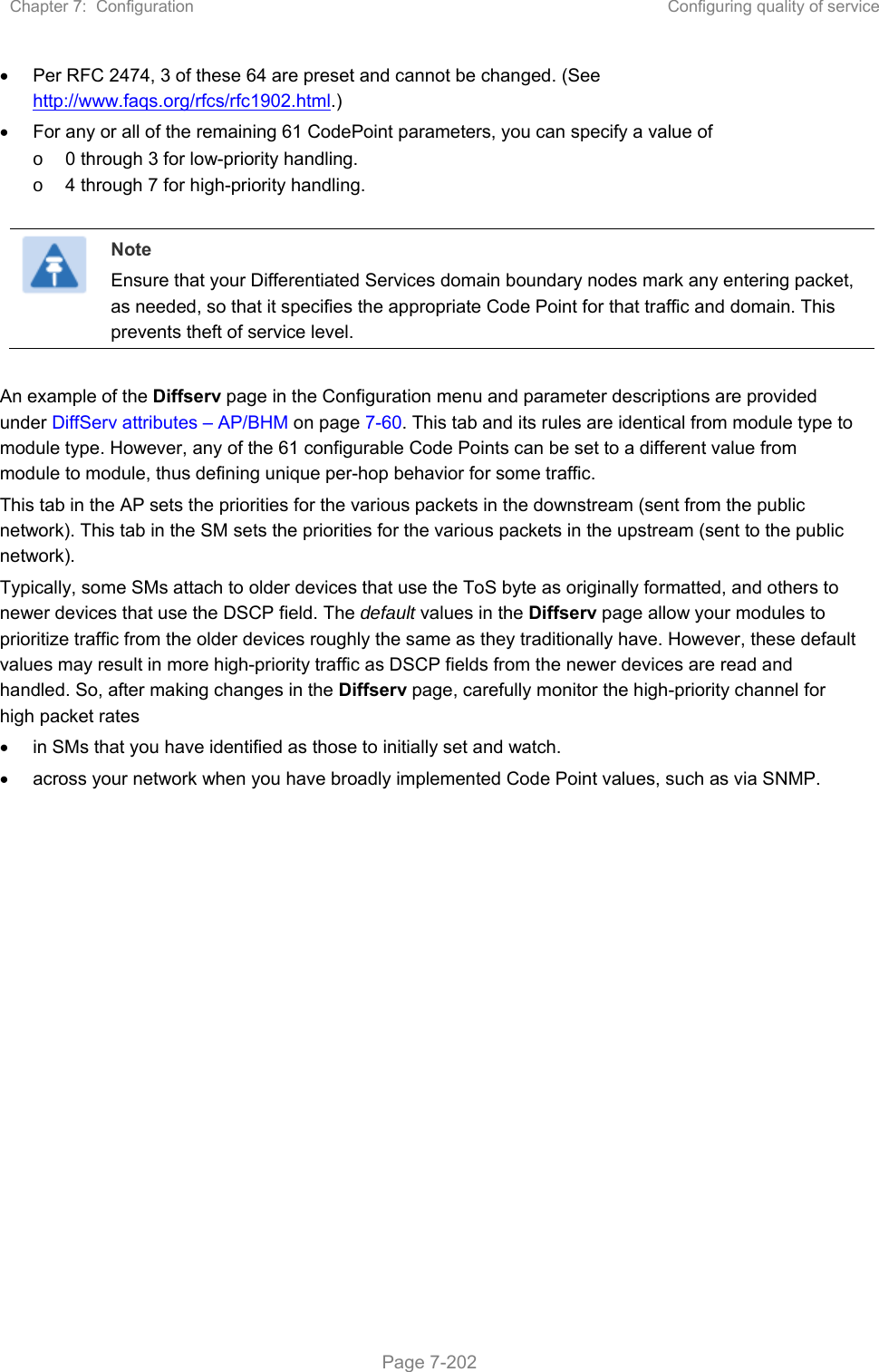

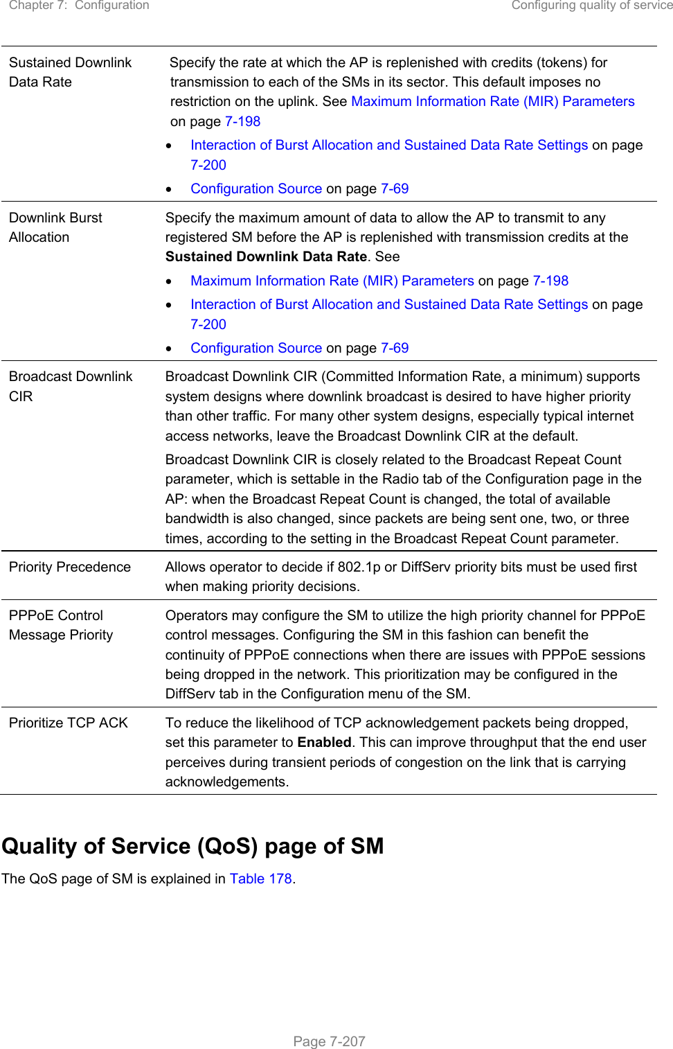
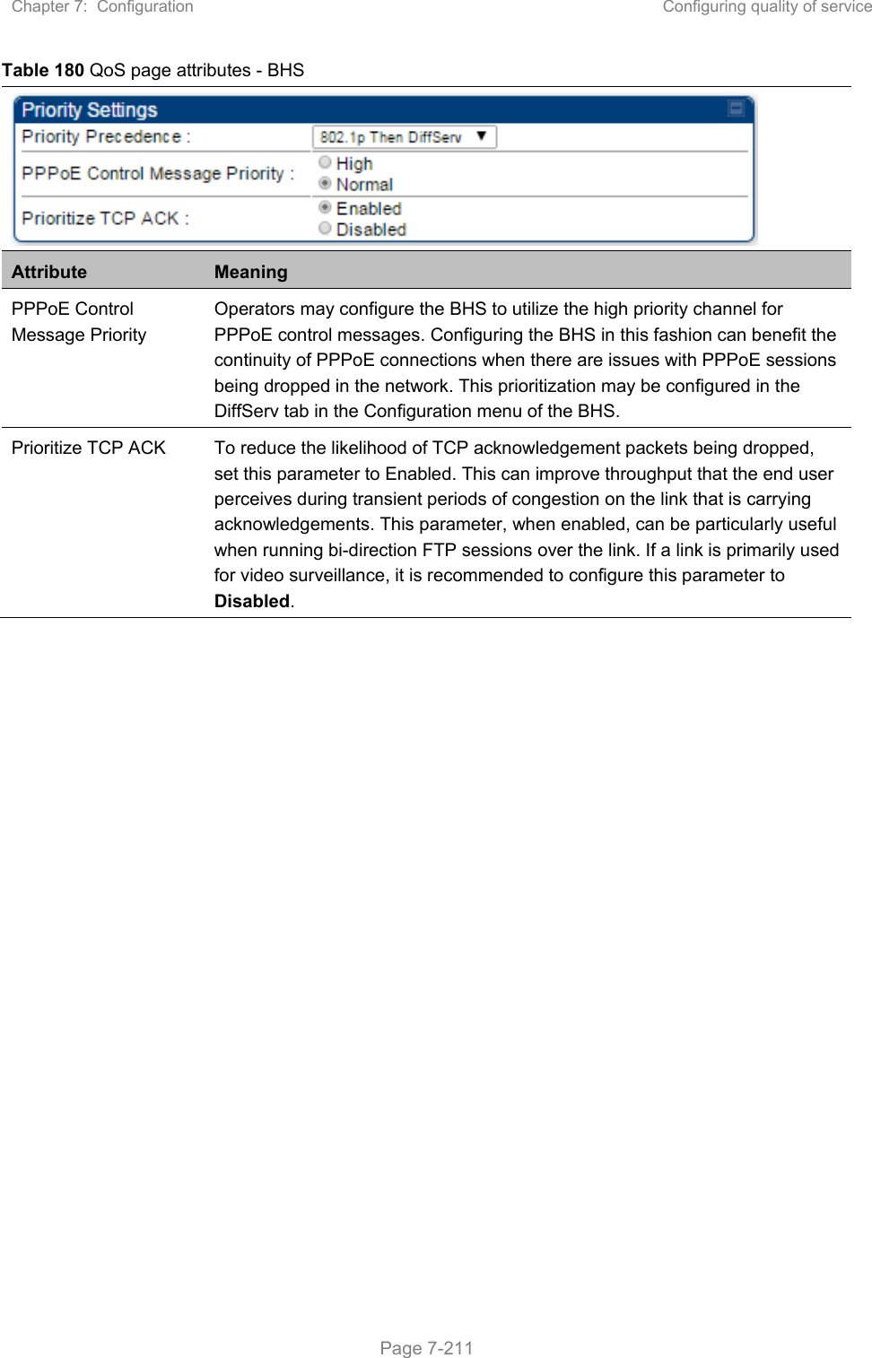
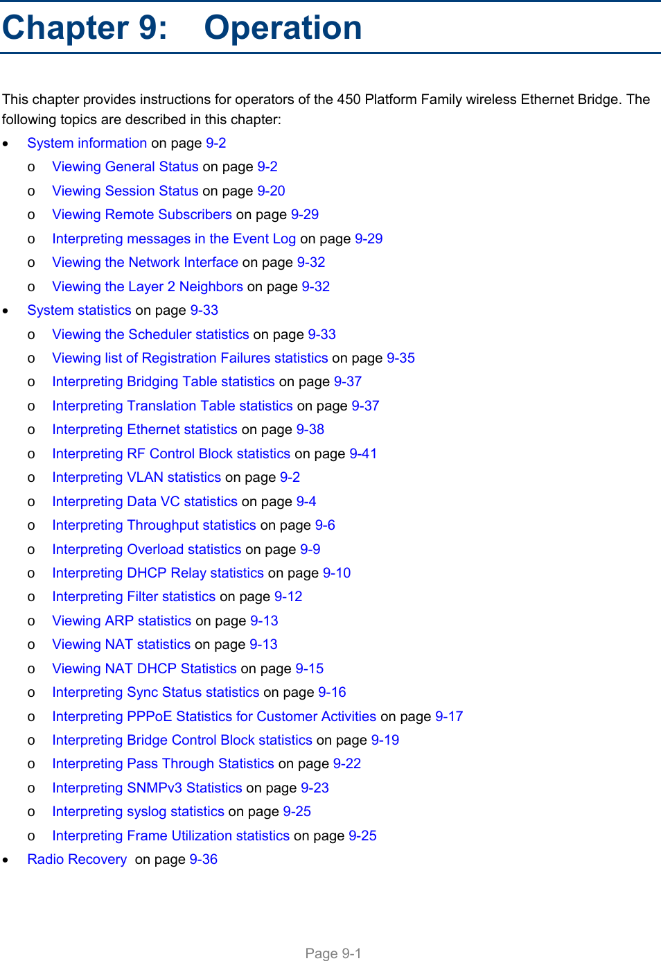
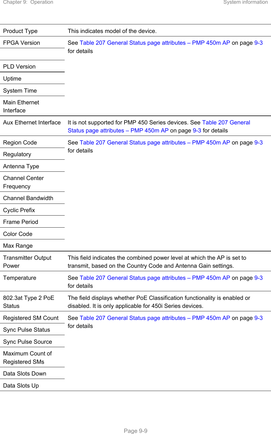
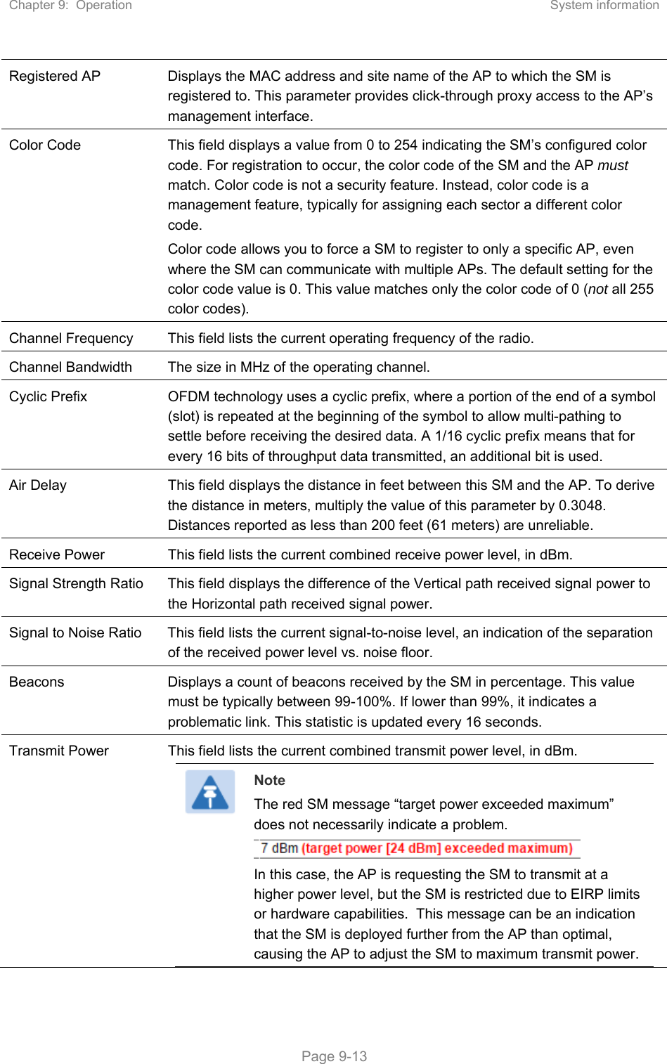
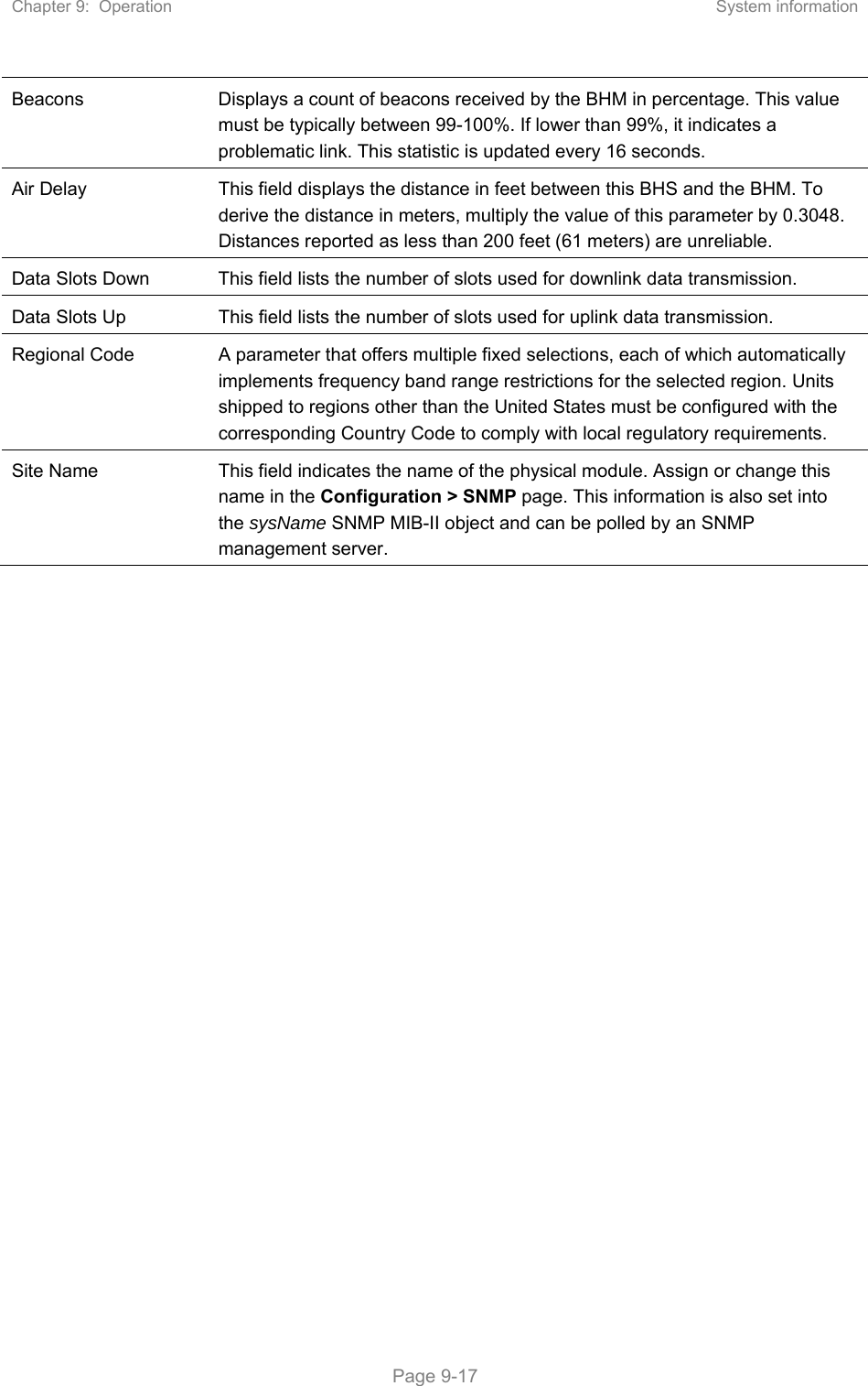
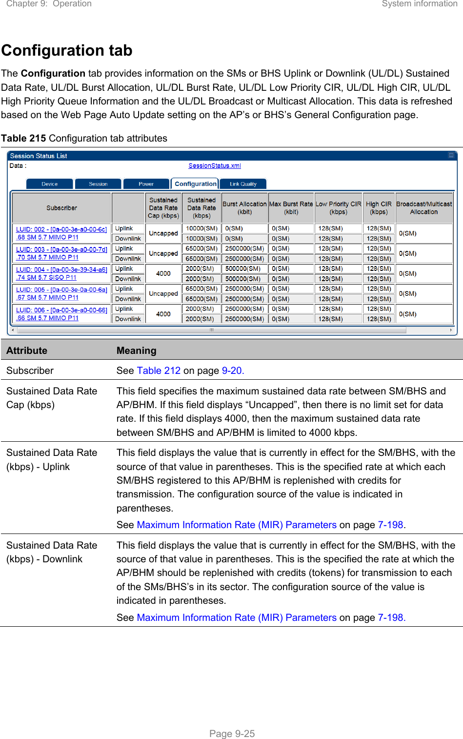
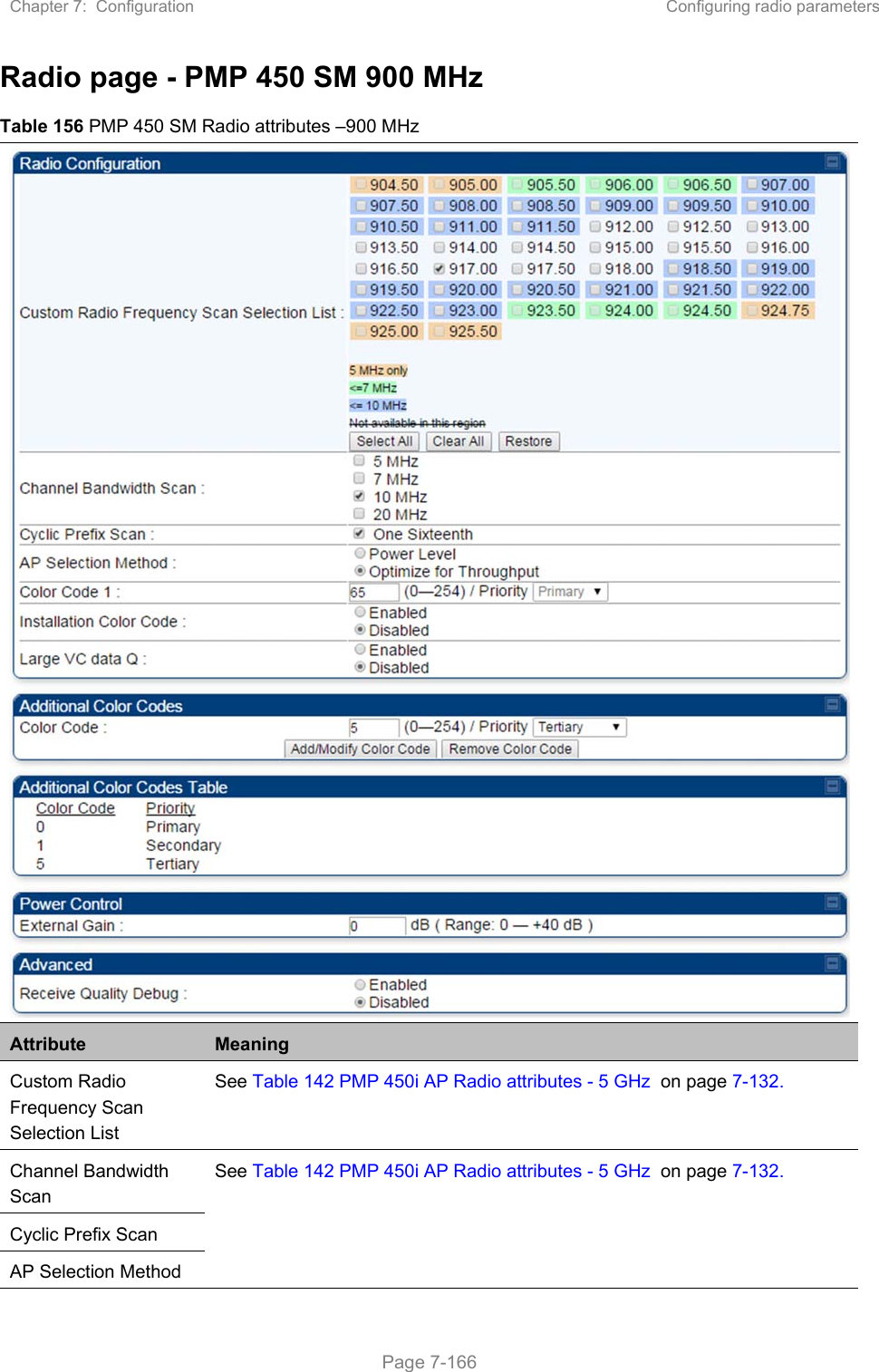
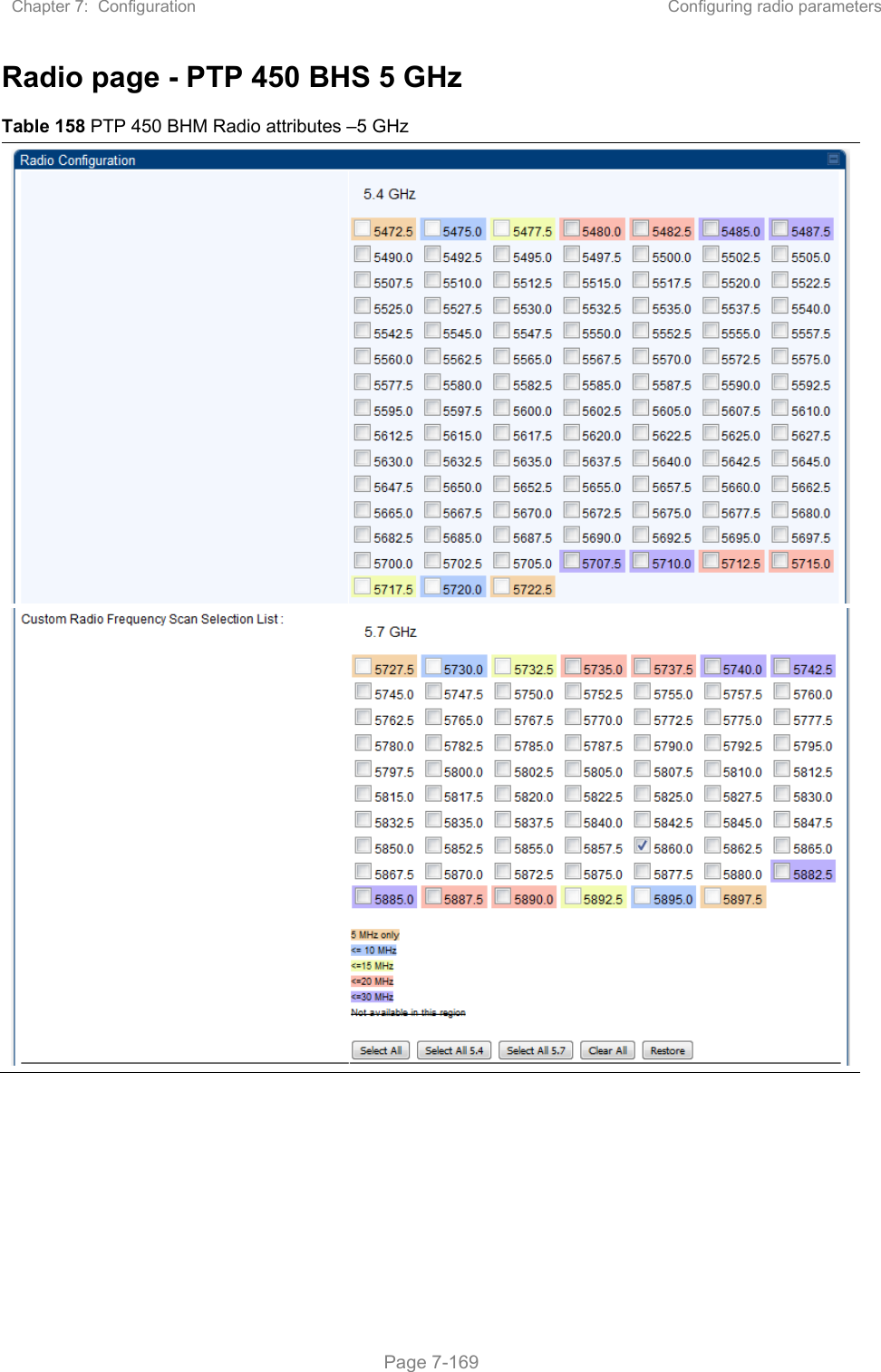
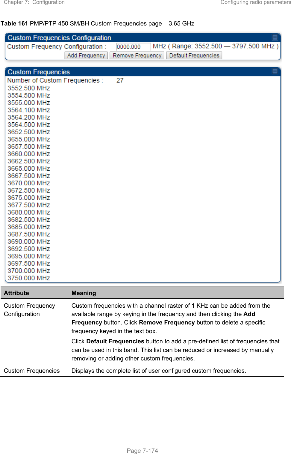
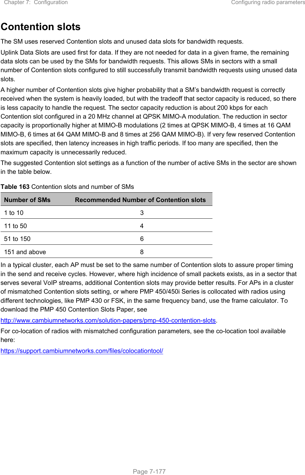
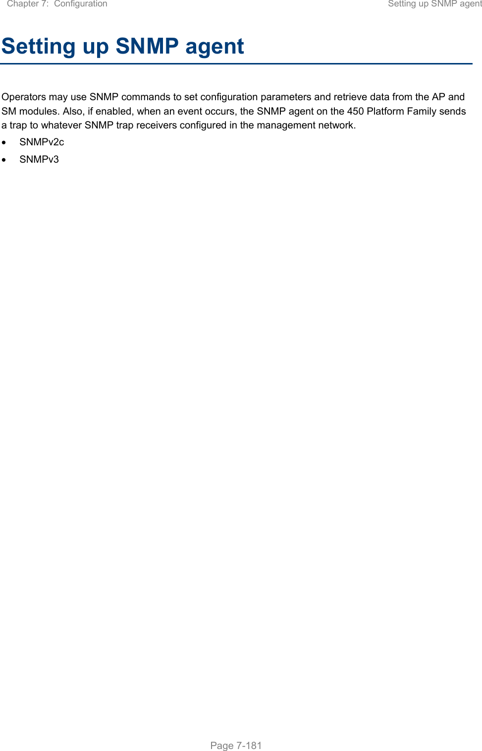
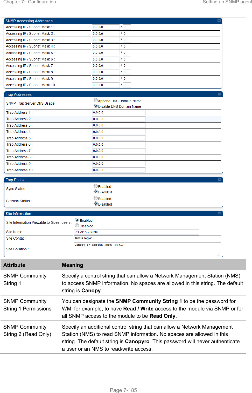
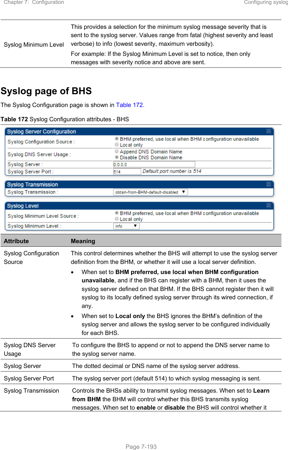
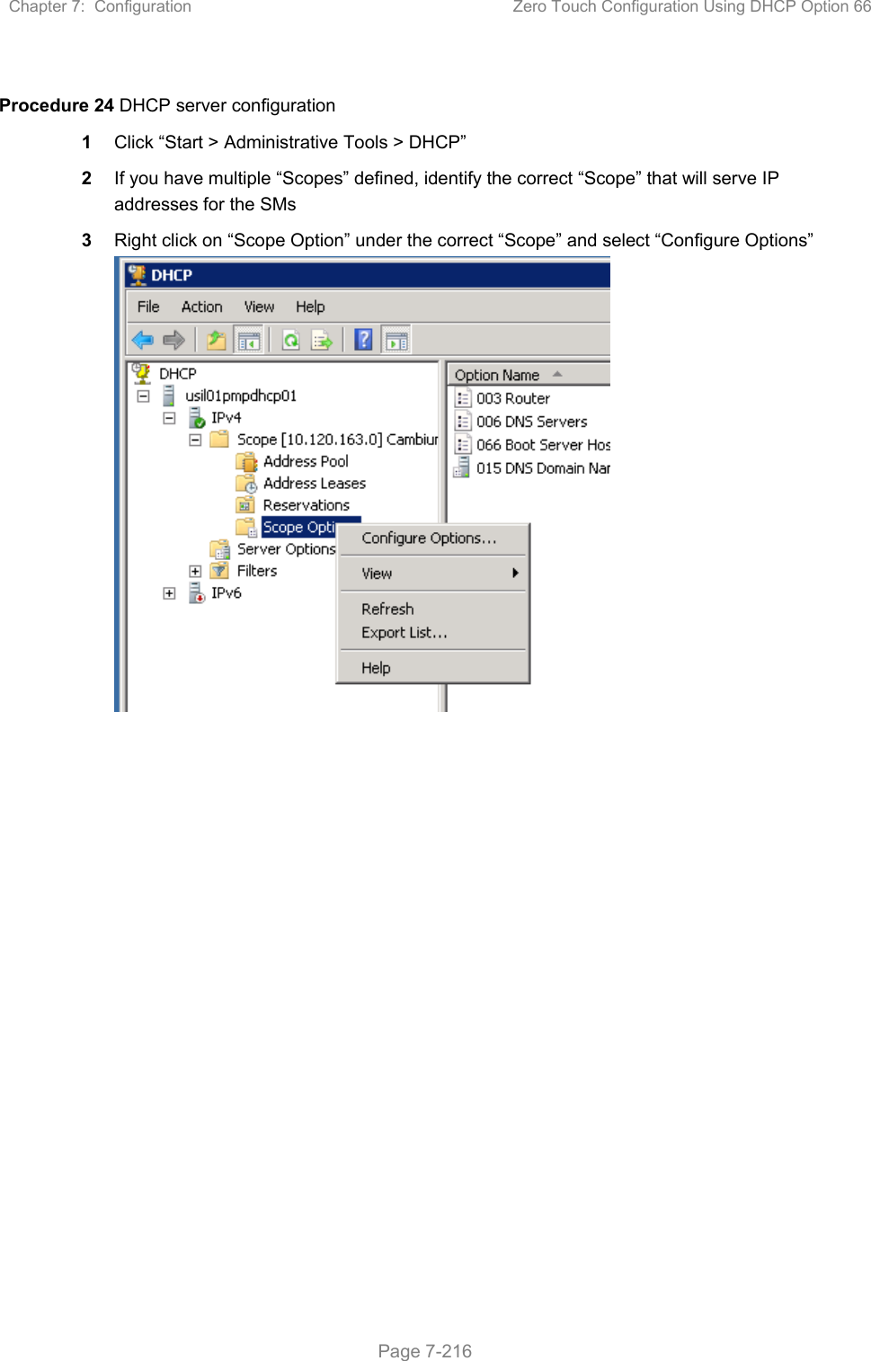
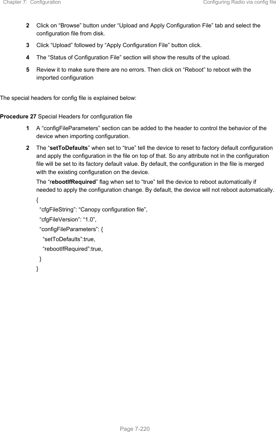
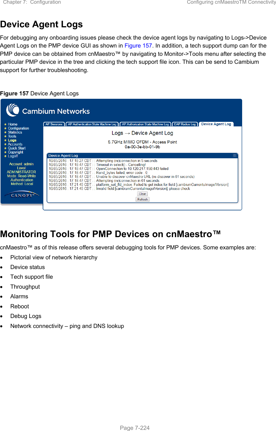
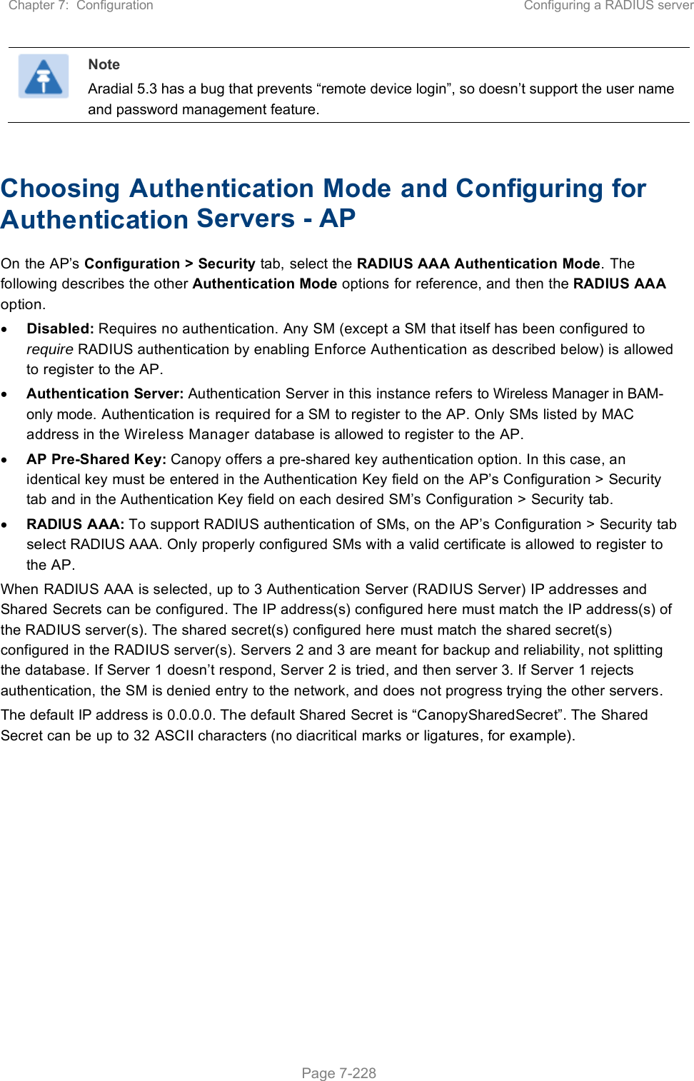
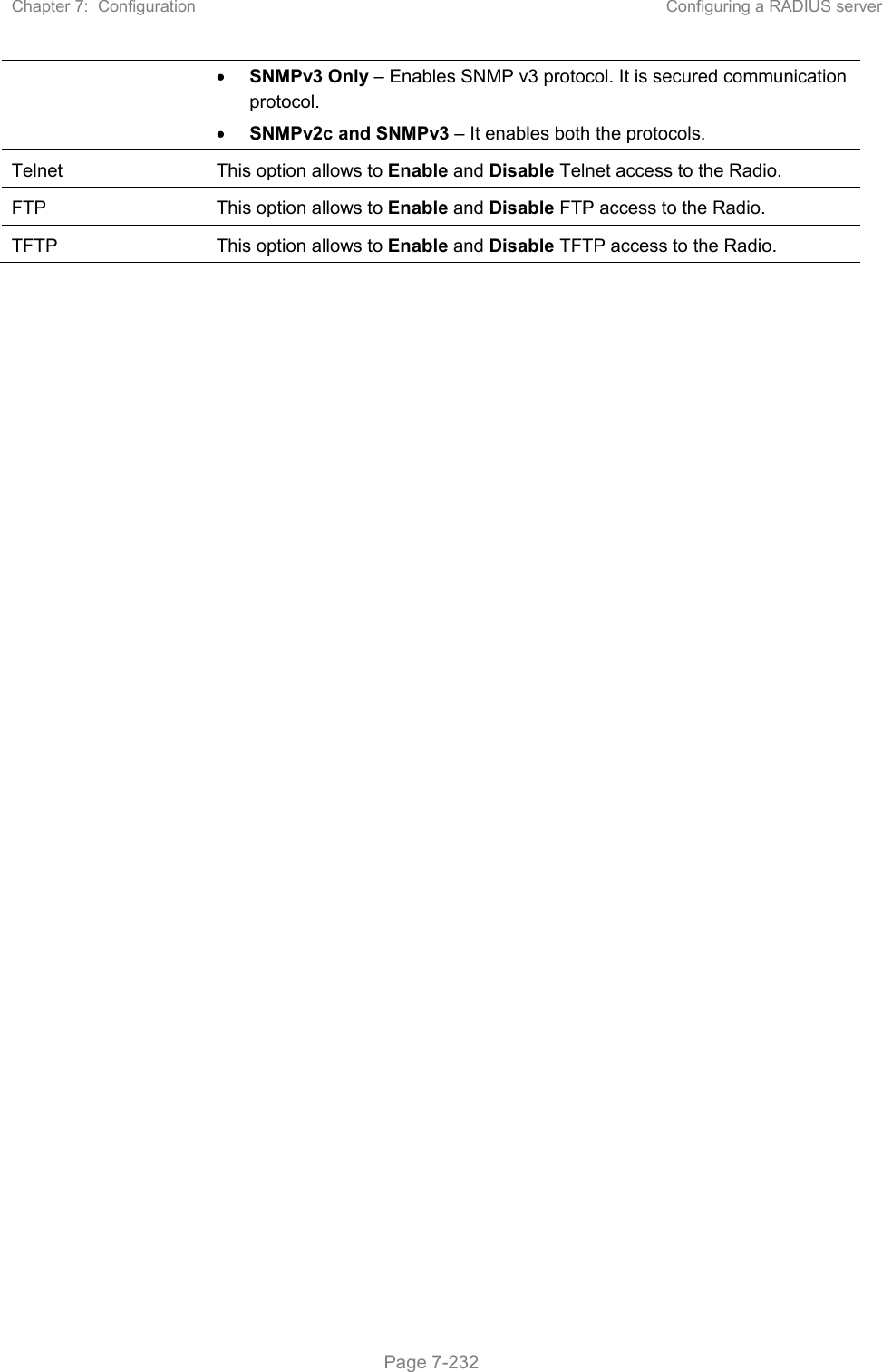
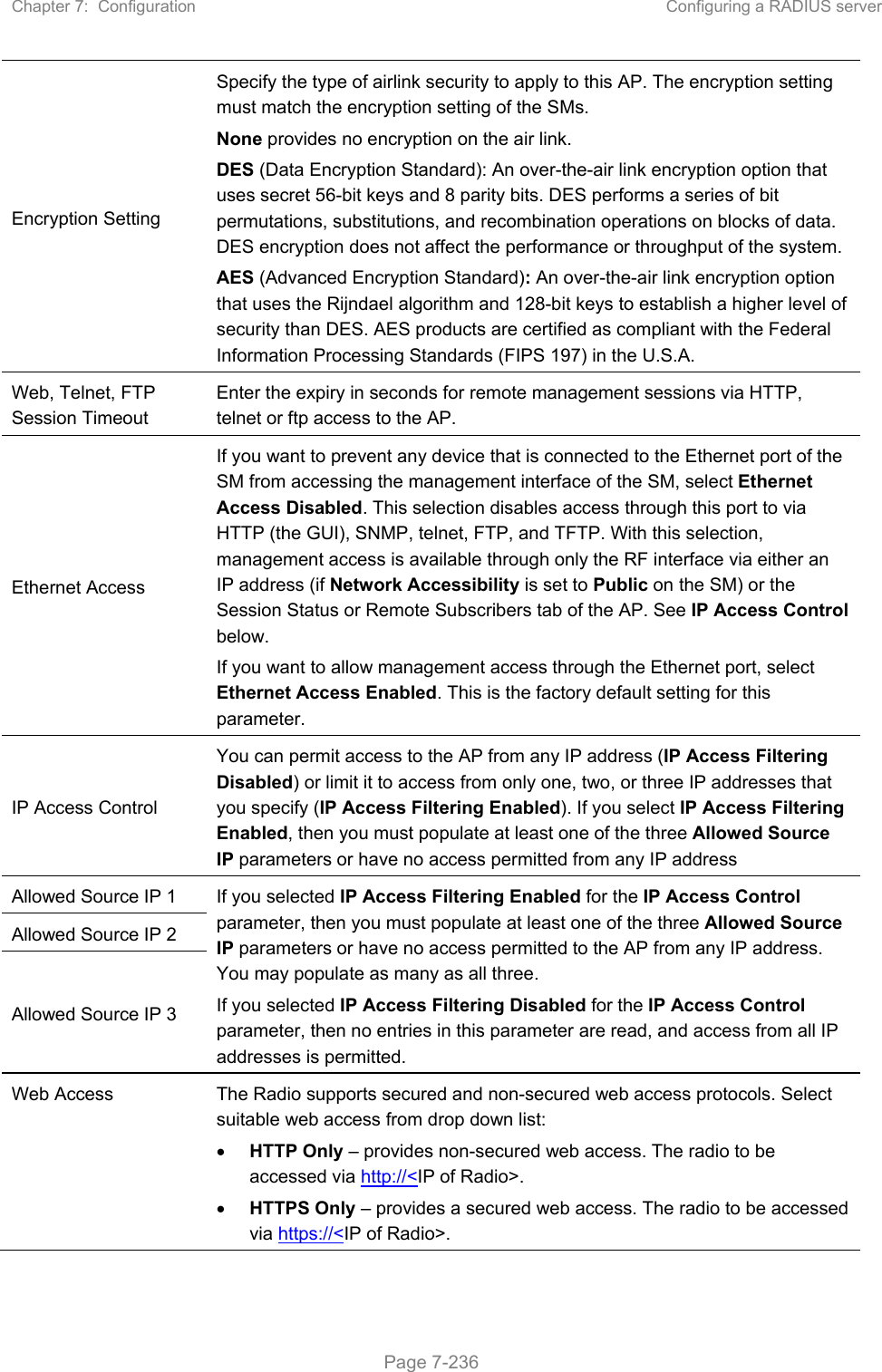
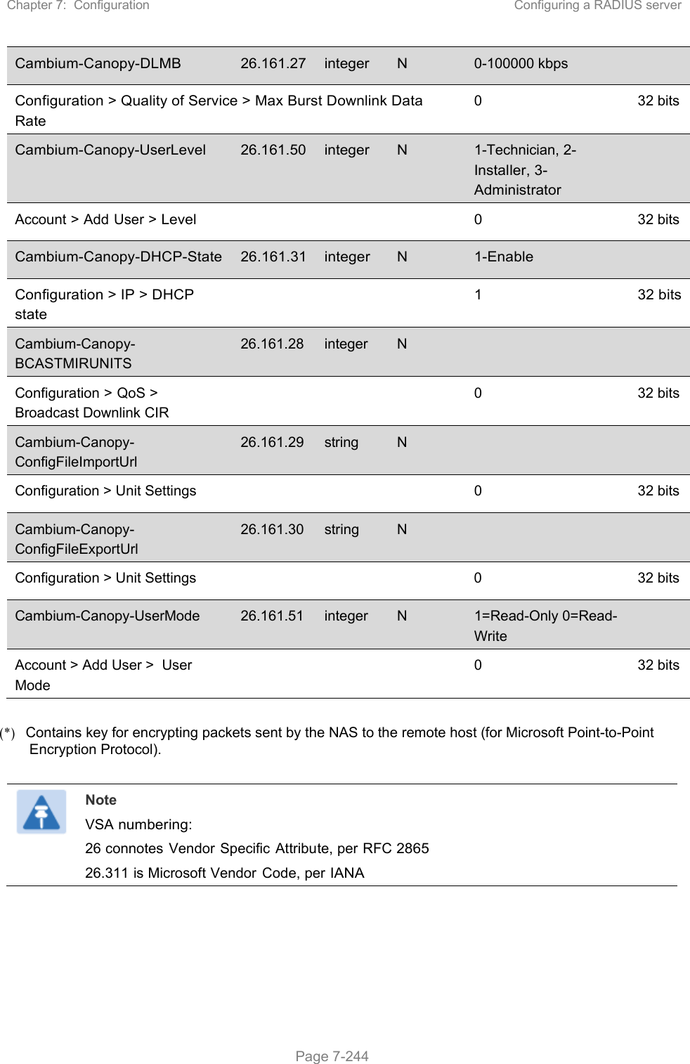
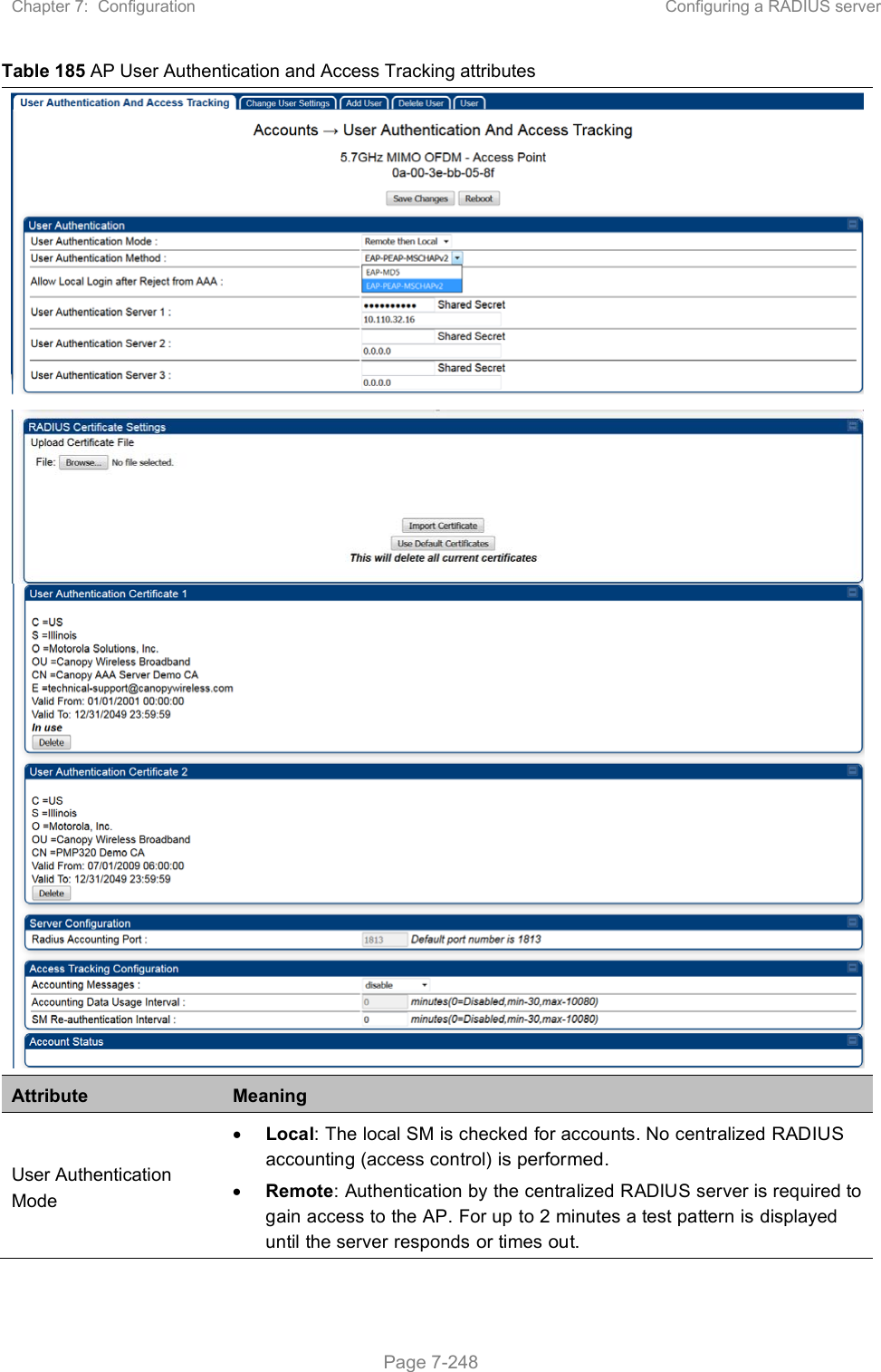
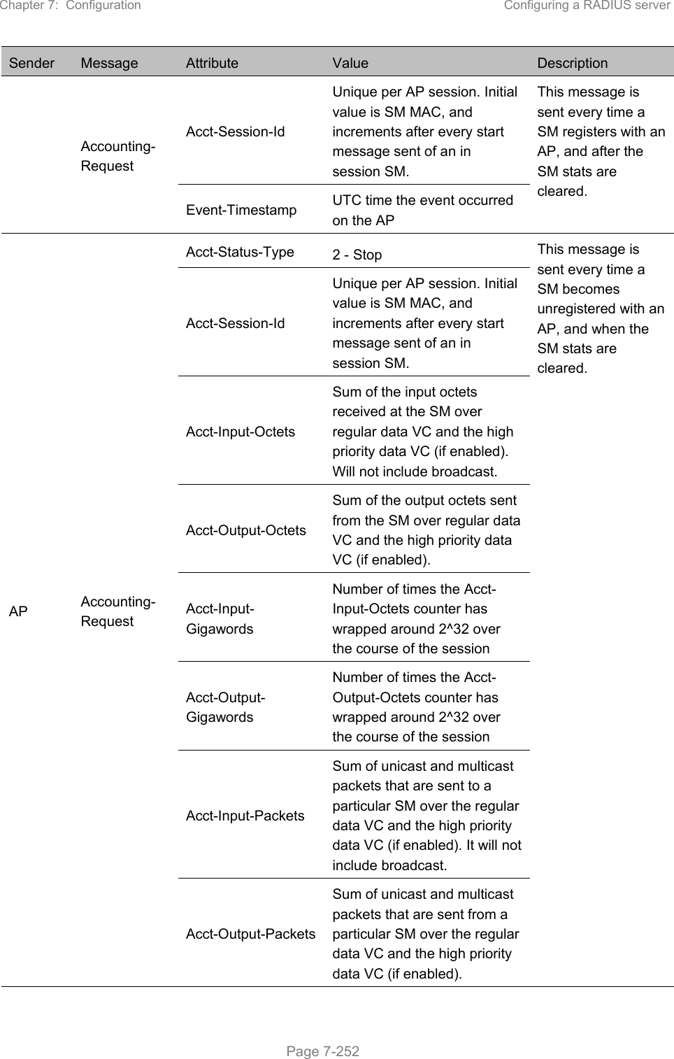
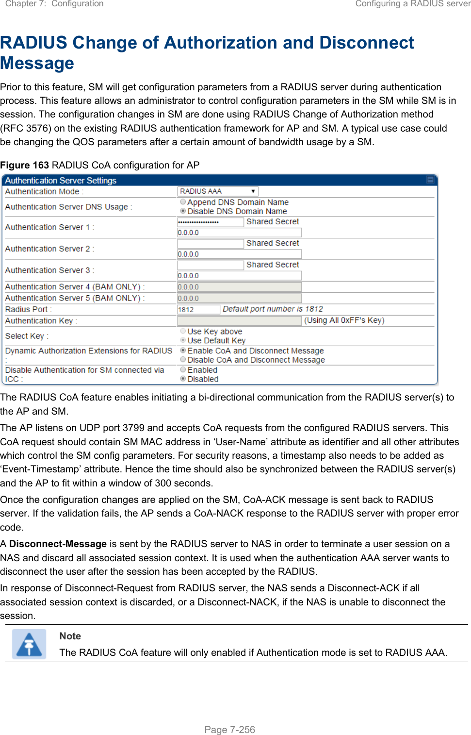
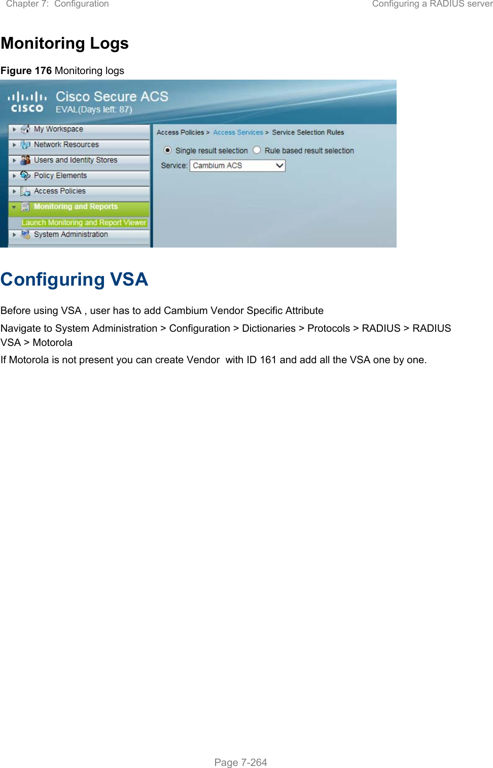
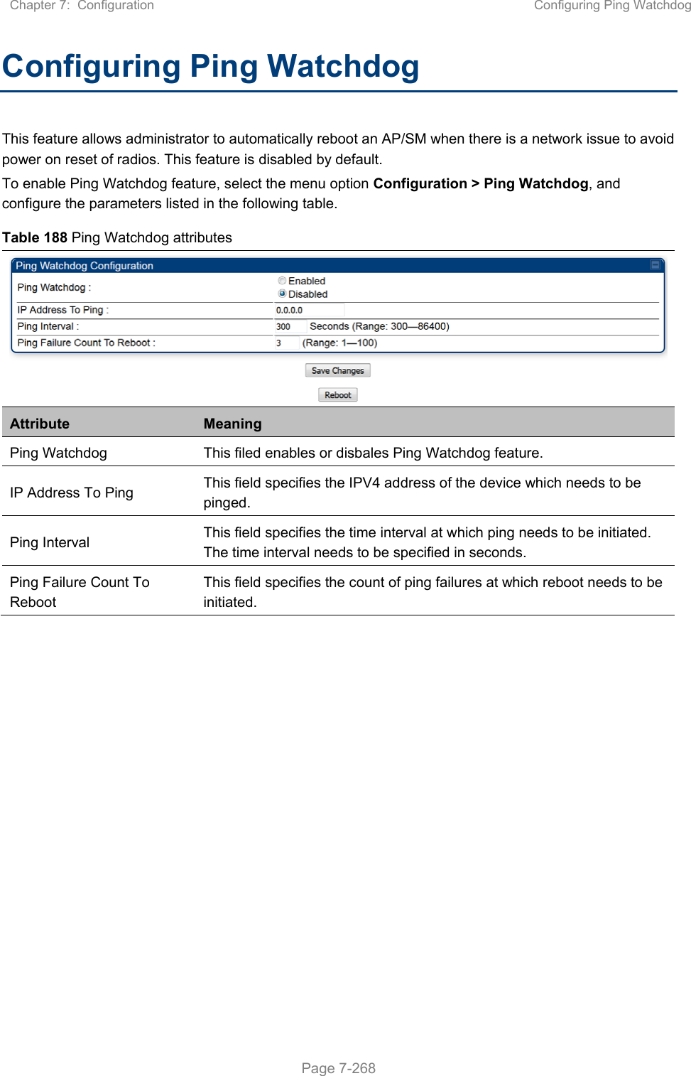
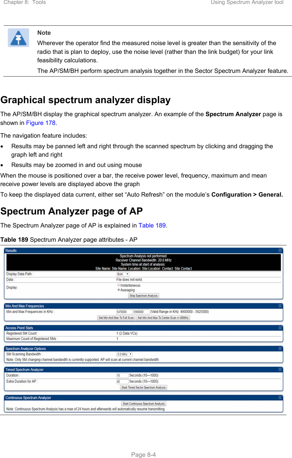
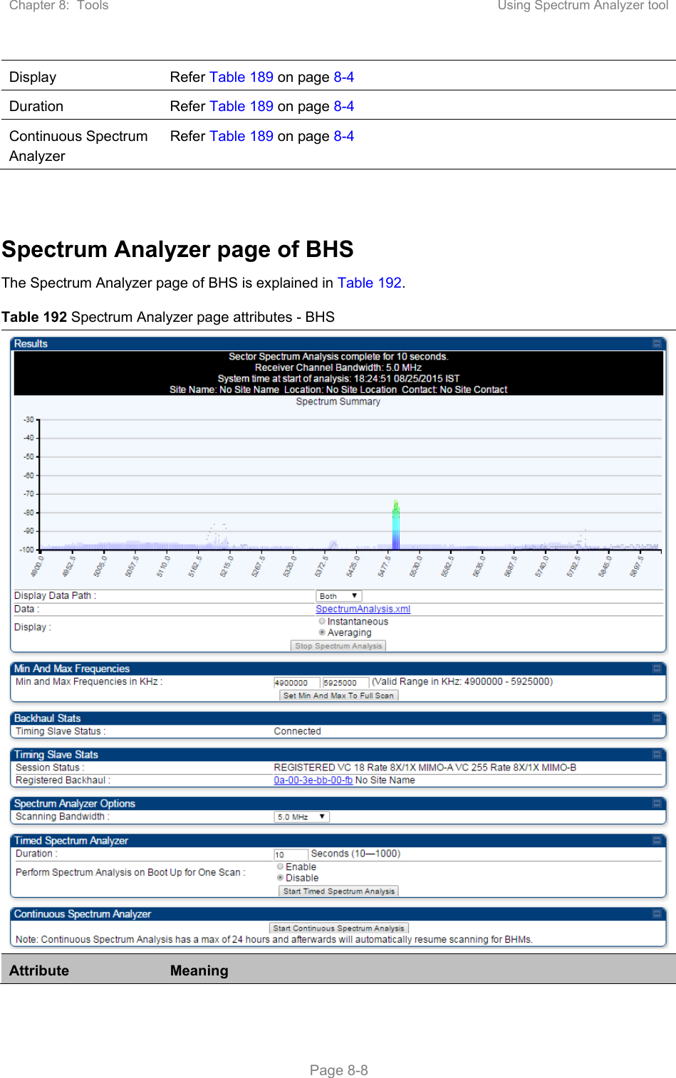
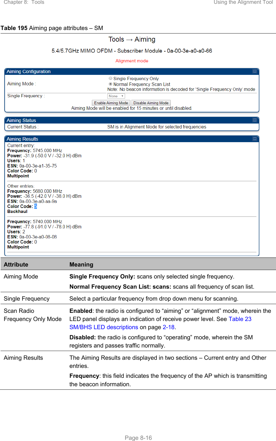
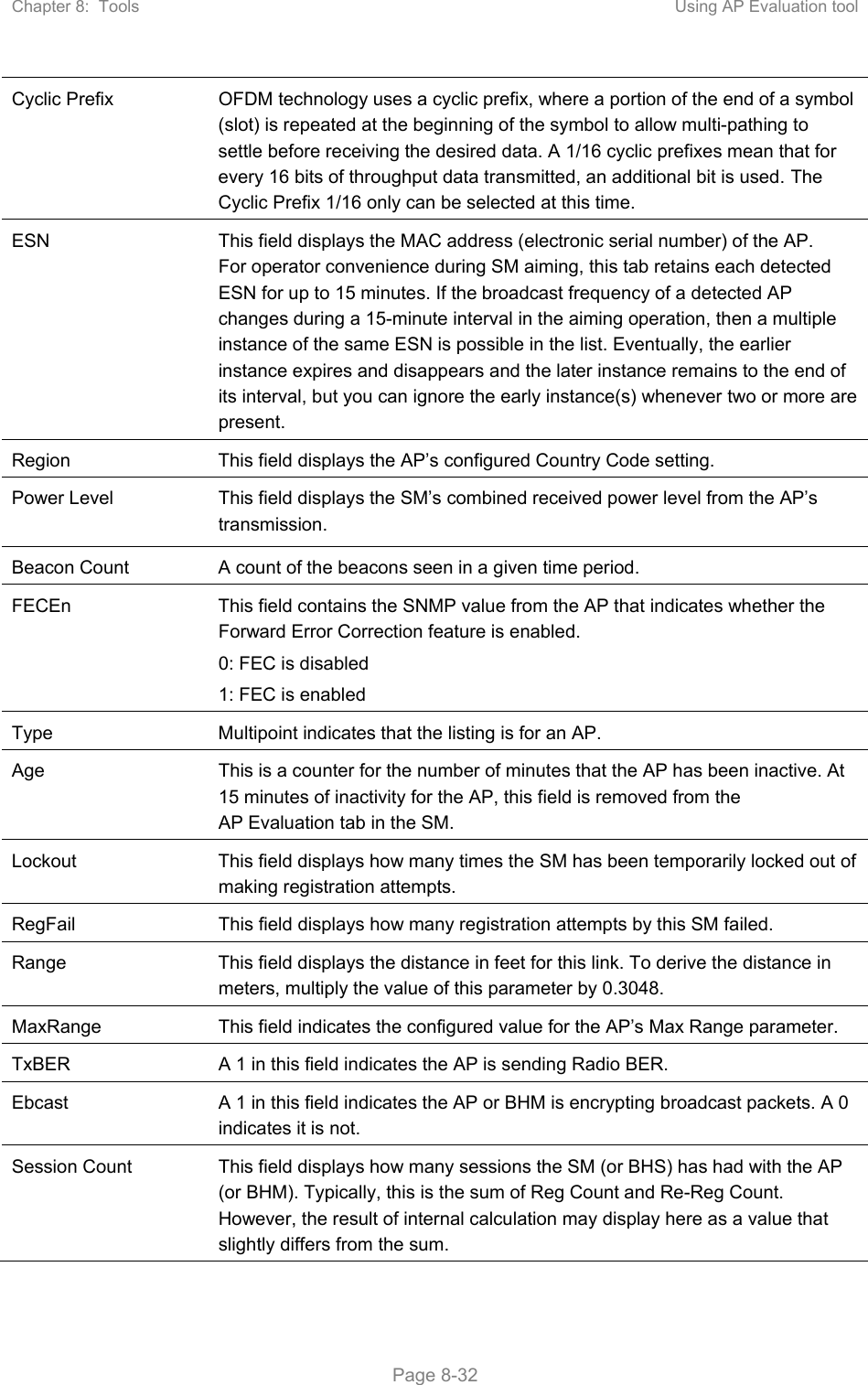
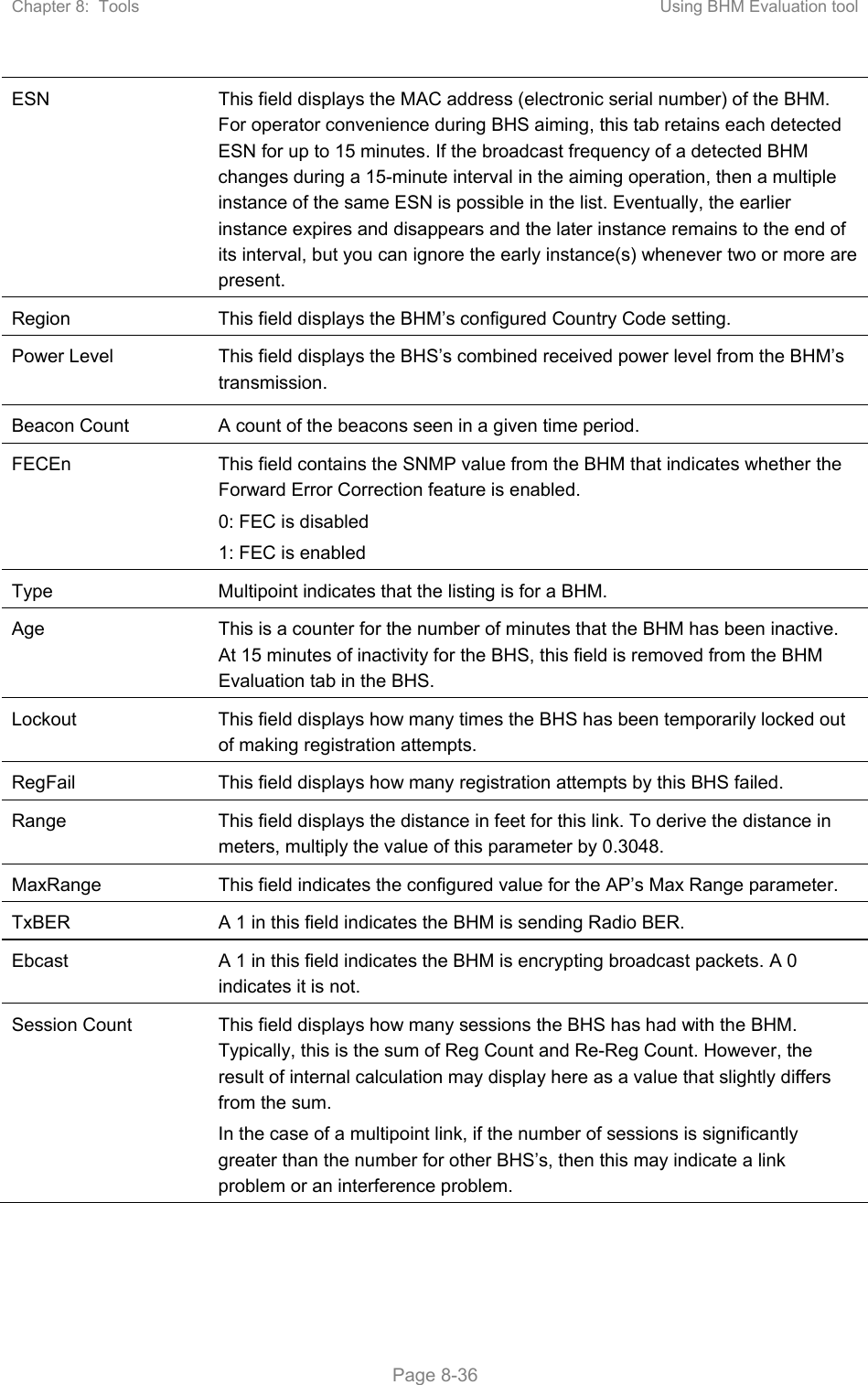
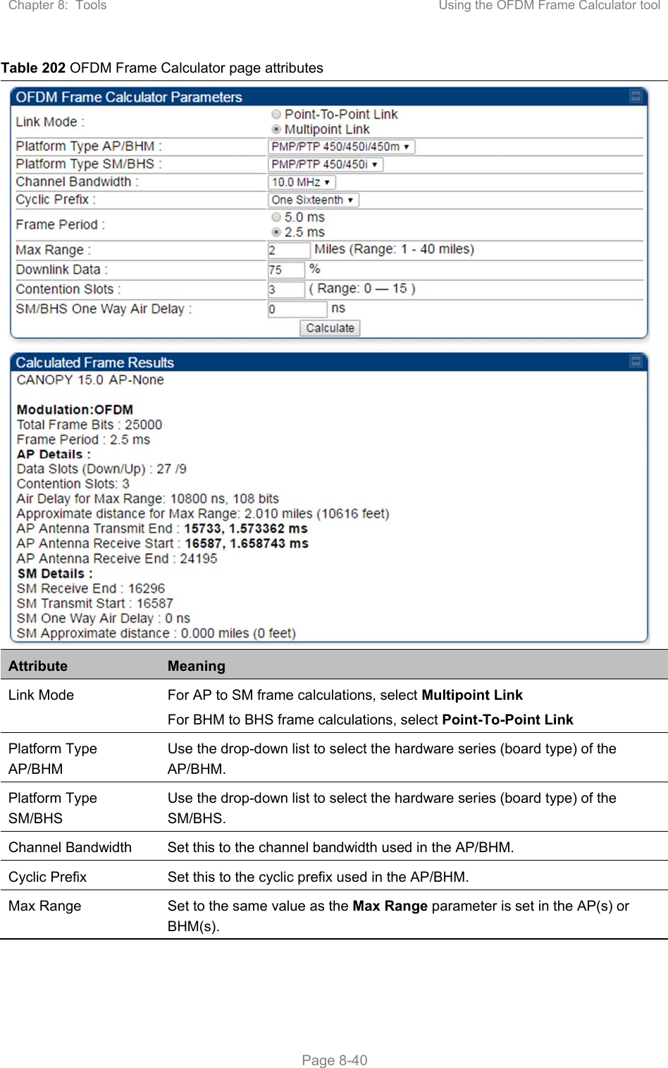
![Chapter 7: Configuration Zero Touch Configuration Using DHCP Option 66 Page 7-215 5475000, 5480000 ], “colorCodeList”: [ { “colorCode”: 42, “priority”: 1 } ] }, “networkConfig”: { “lanDhcpState”: 1 } }, “cfgFileVersion”: “1.0”, “cfgFileString”: “Canopy configuration file”, “configFileParameters”: { “rebootIfRequired”: true } } When configuration is imported, only the items that exist in the configuration file are modified. Parameters that are not in the imported file are not changed. If user wish to revert those settings to their factory default values, please add a “setToDefaults” item under “configFileParameters” section with a value of true. “cfgFileVersion”: “1.0”, “cfgFileString”: “Canopy configuration file”, “configFileParameters”: { “rebootIfRequired”: true, “setToDefaults”: true } In case, the SM needs to fetch the configuration file on each boot up even when not connecting to AP via ICC, set “Network Accessibility” to “Public” and “DHCP State” to “Enabled” in the “Configuration > IP” page before exporting the configuration. Hosting the config file Copy the golden configuration file to an FTP, TFTP, HTTP or HTTPS server. This location can be password protected; you just have to include the user name and password in the URL. DHCP server configuration Configure DHCP server to return the full URL to the golden config file as the value of DHCP option 66. The following example explains how to make the change for Windows Server 2008. Adapt it to your specific DHCP server.](https://usermanual.wiki/Cambium-Networks/50450M.USERS-MANUAL-PART3/User-Guide-3650908-Page-52.png)
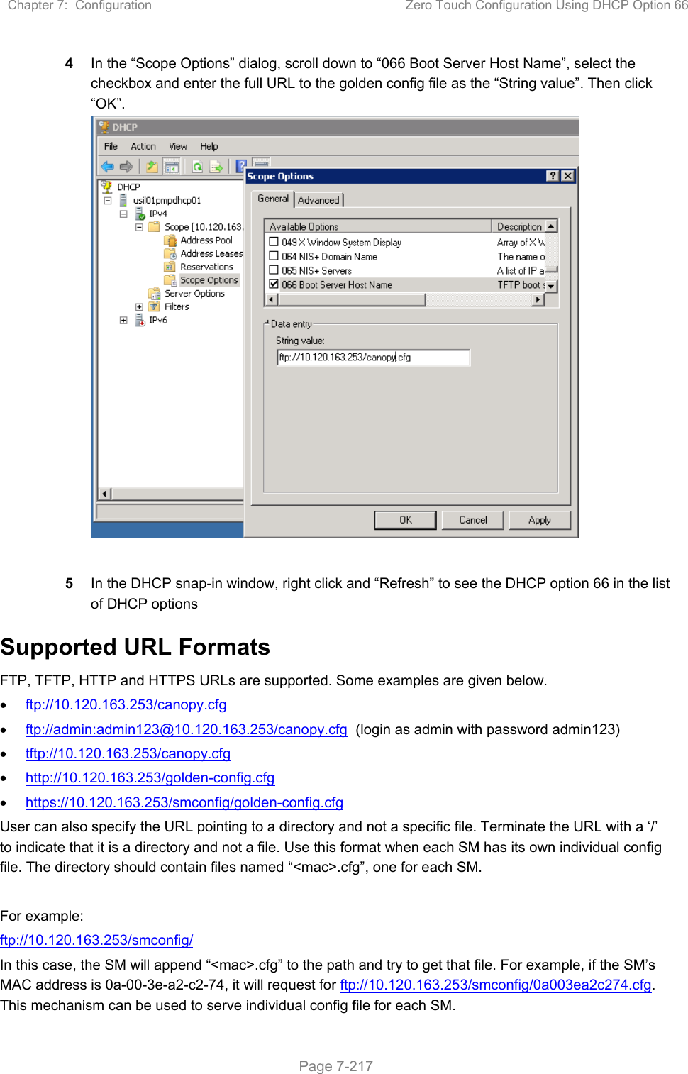
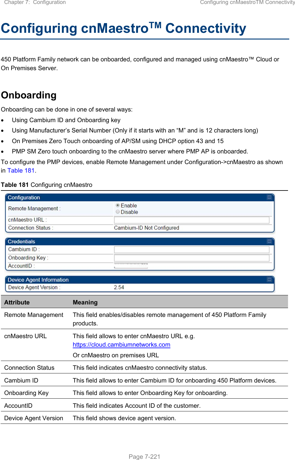
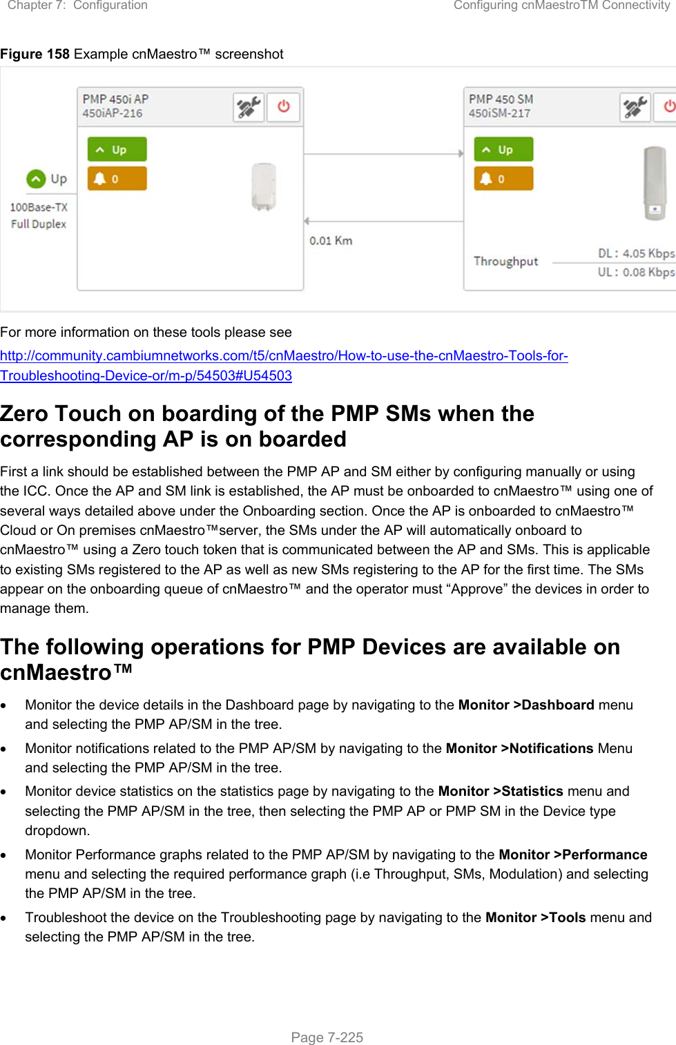
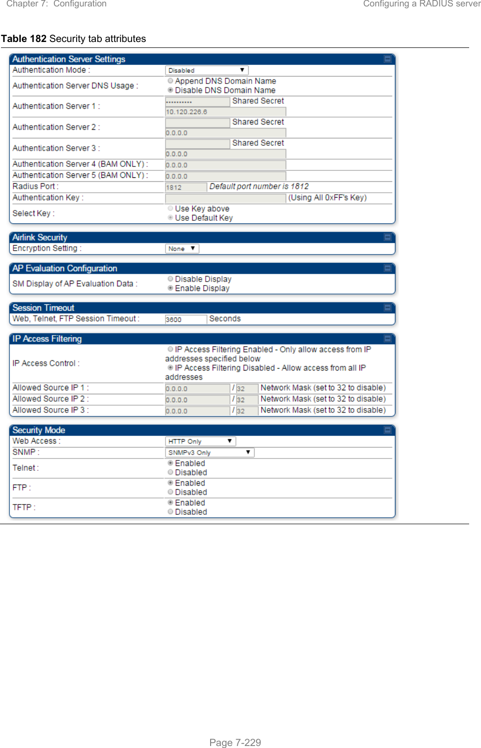
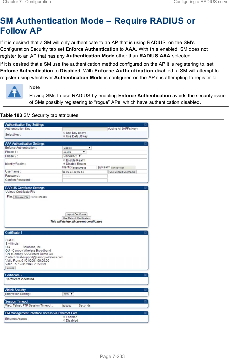
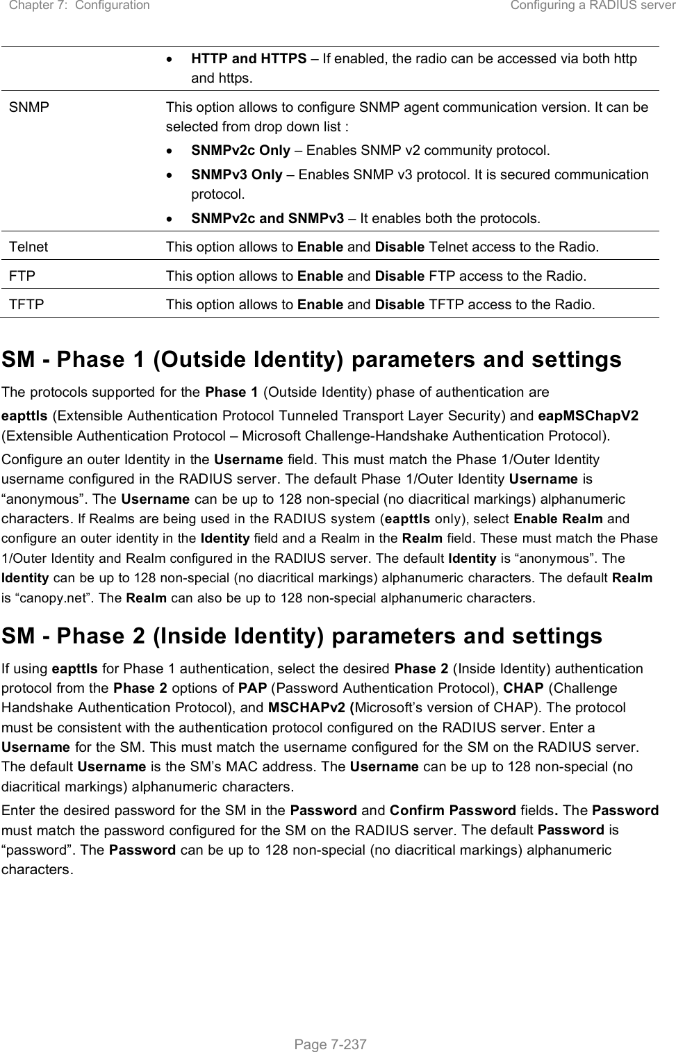
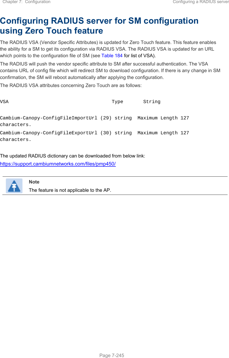
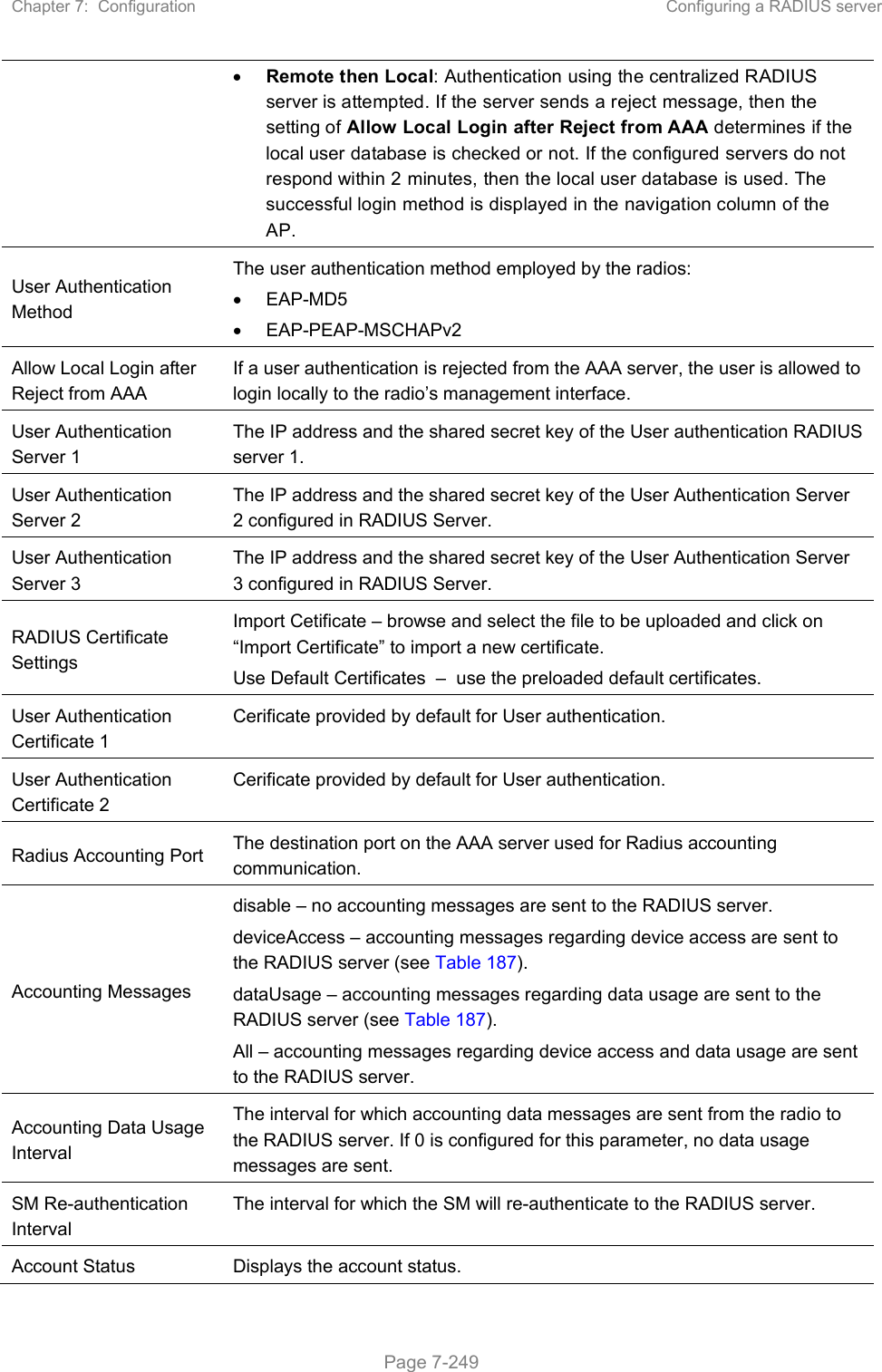
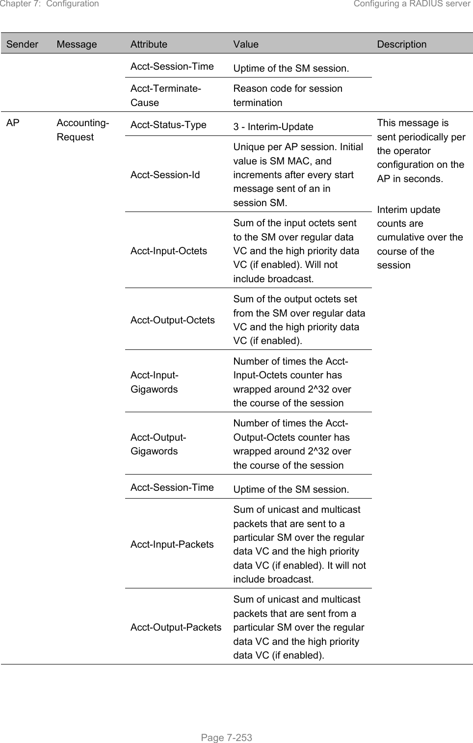
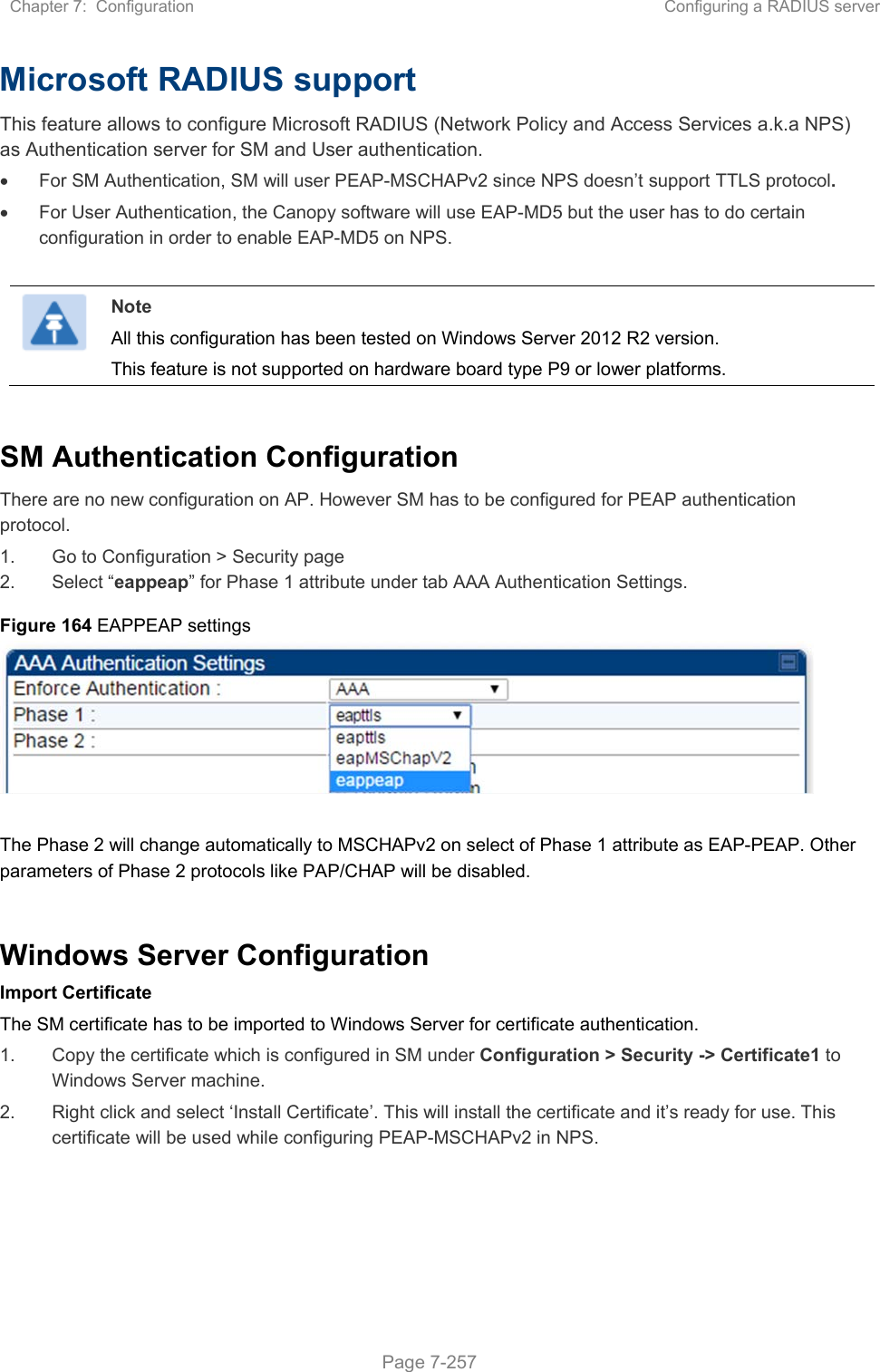
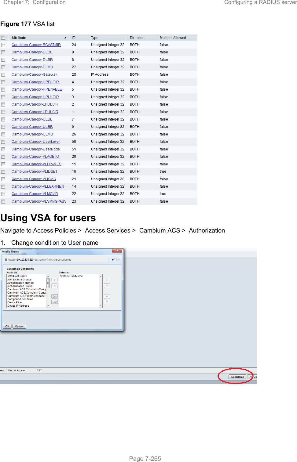
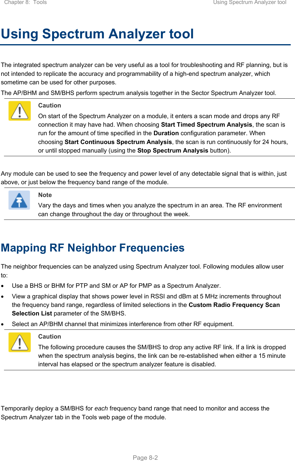
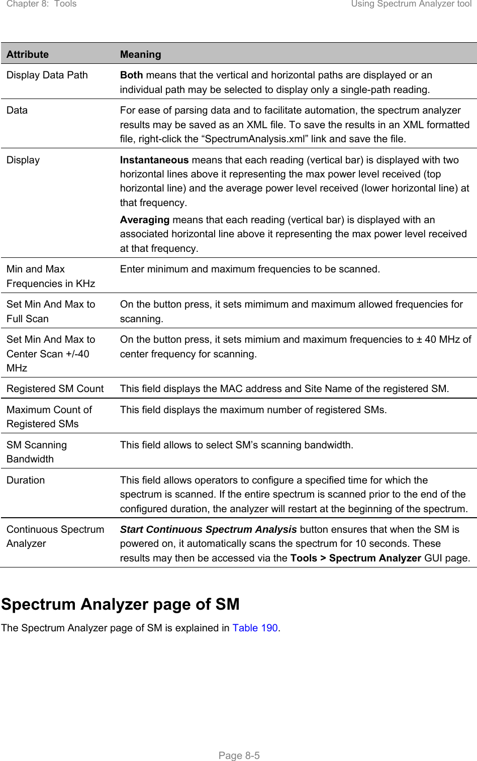
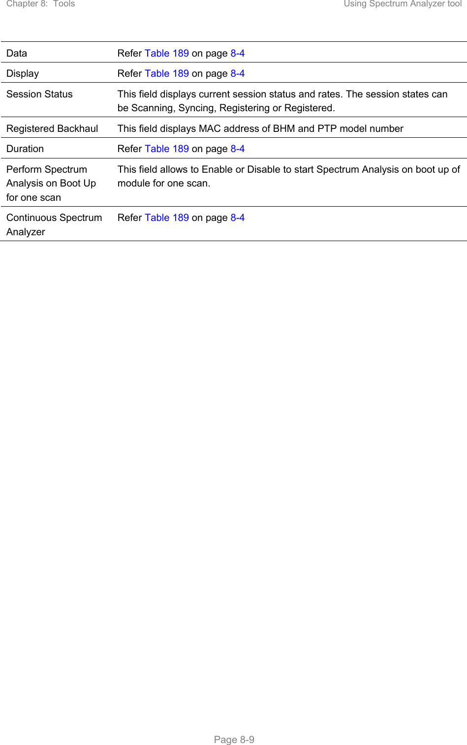
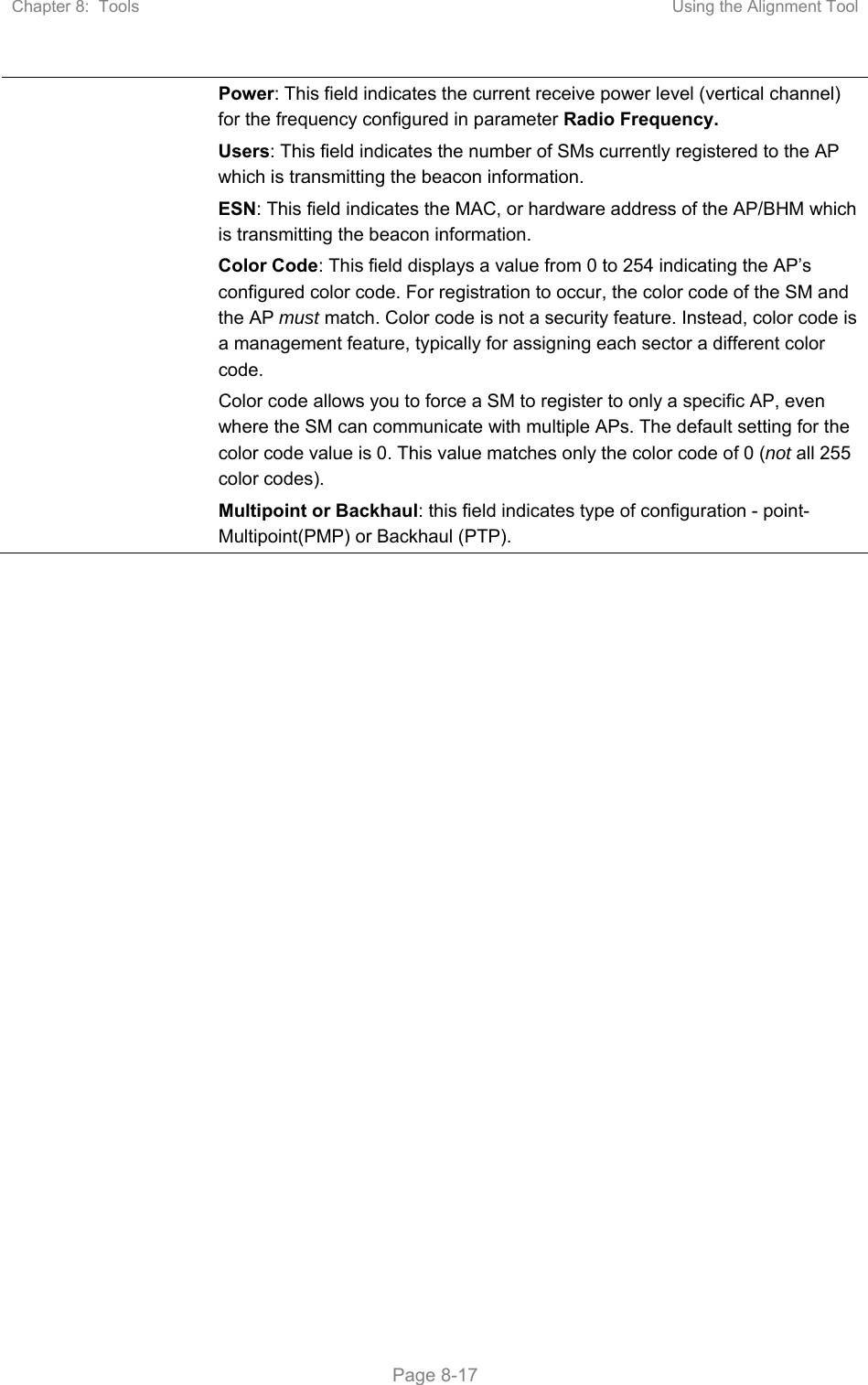
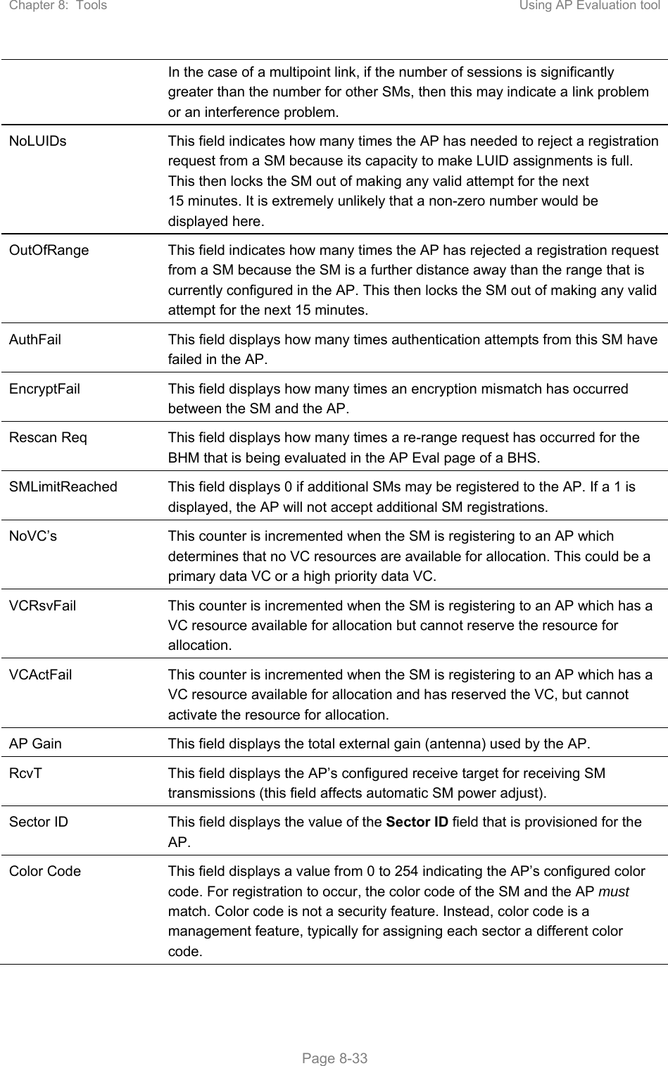
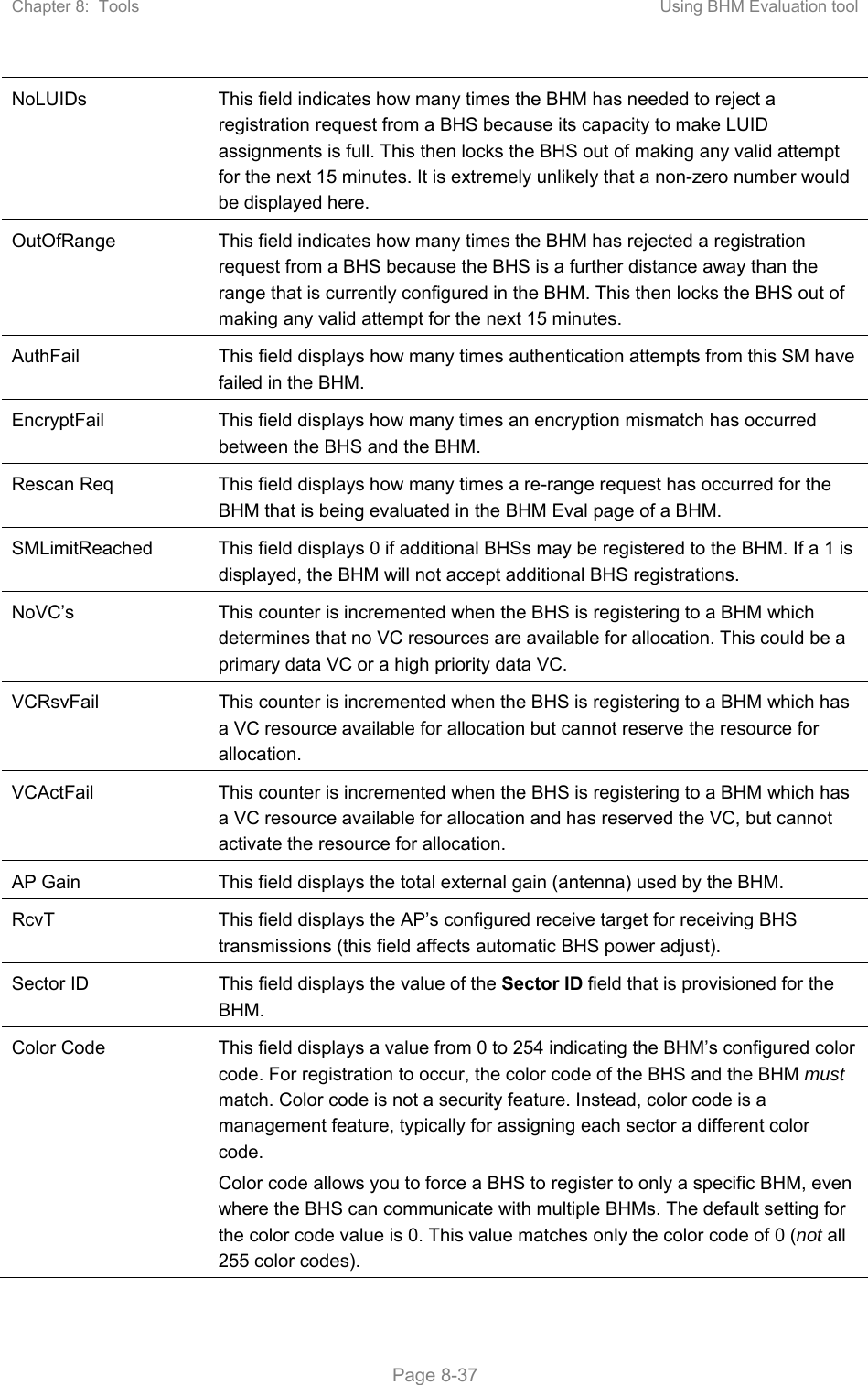


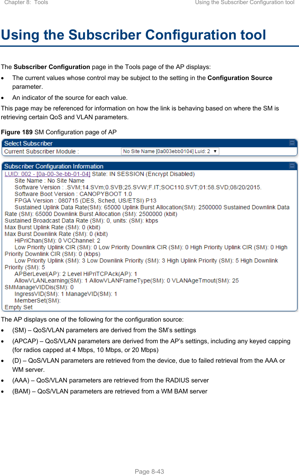
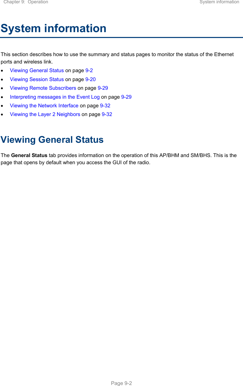
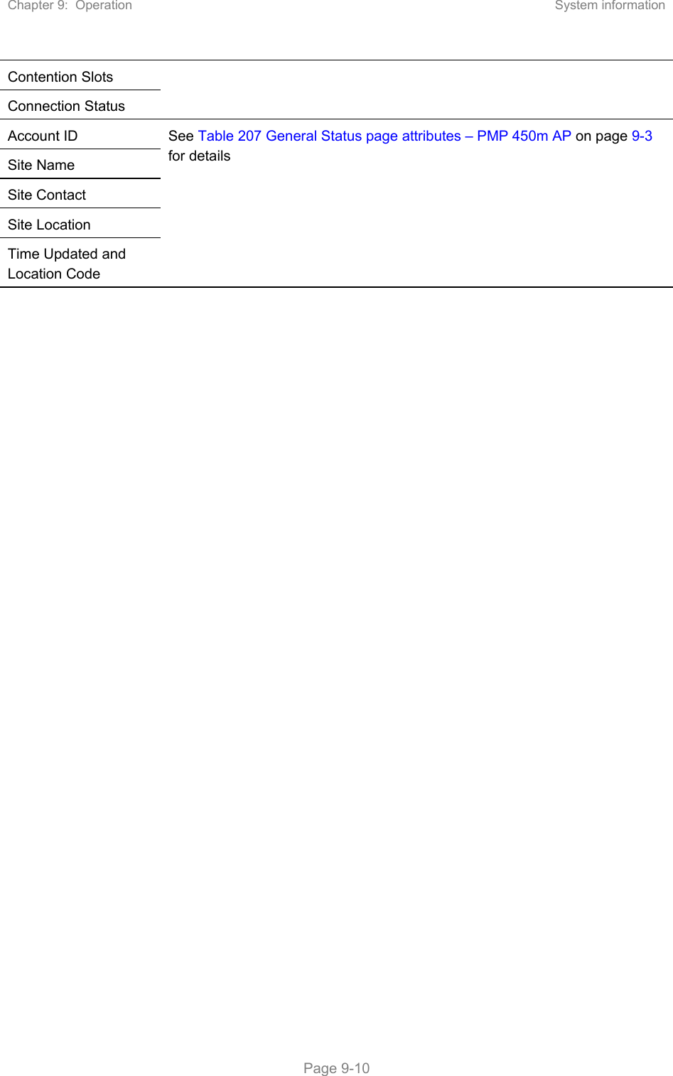
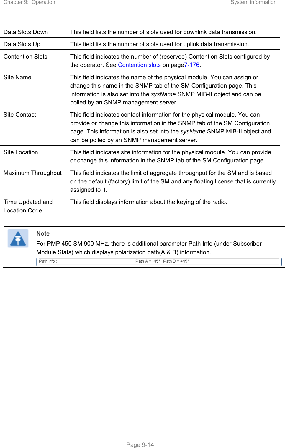
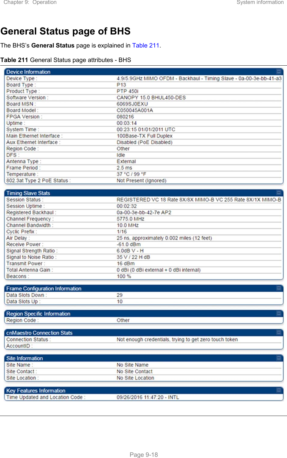
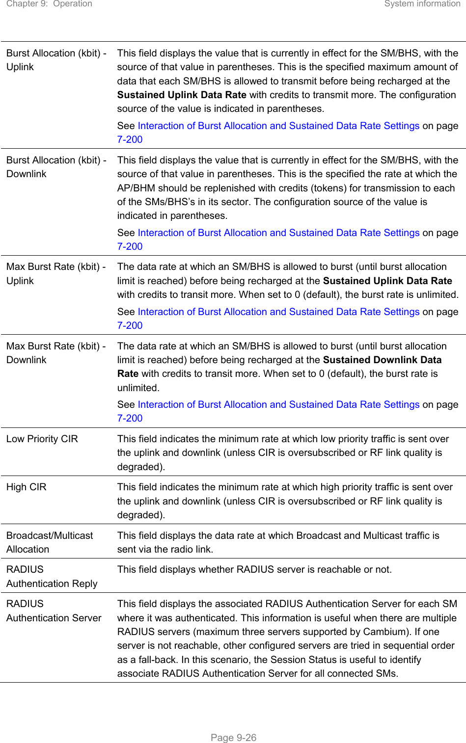
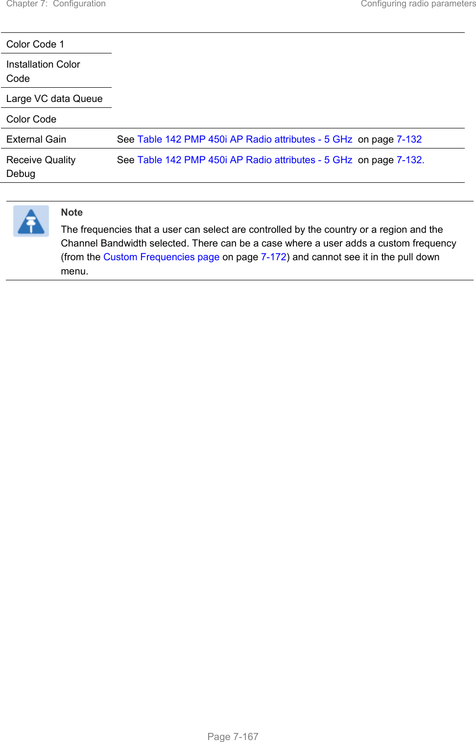
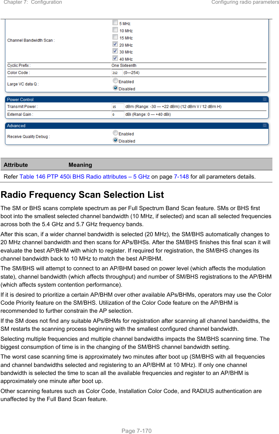
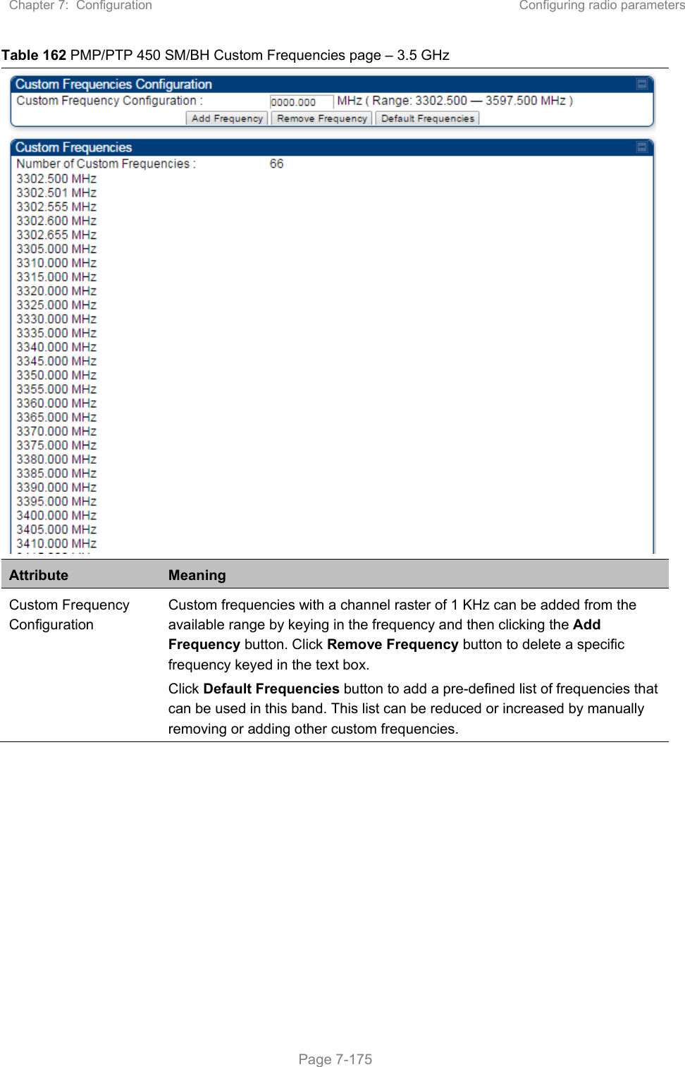
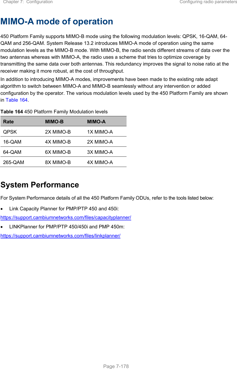
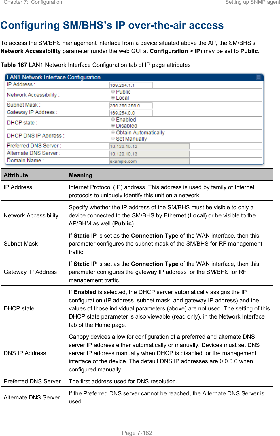
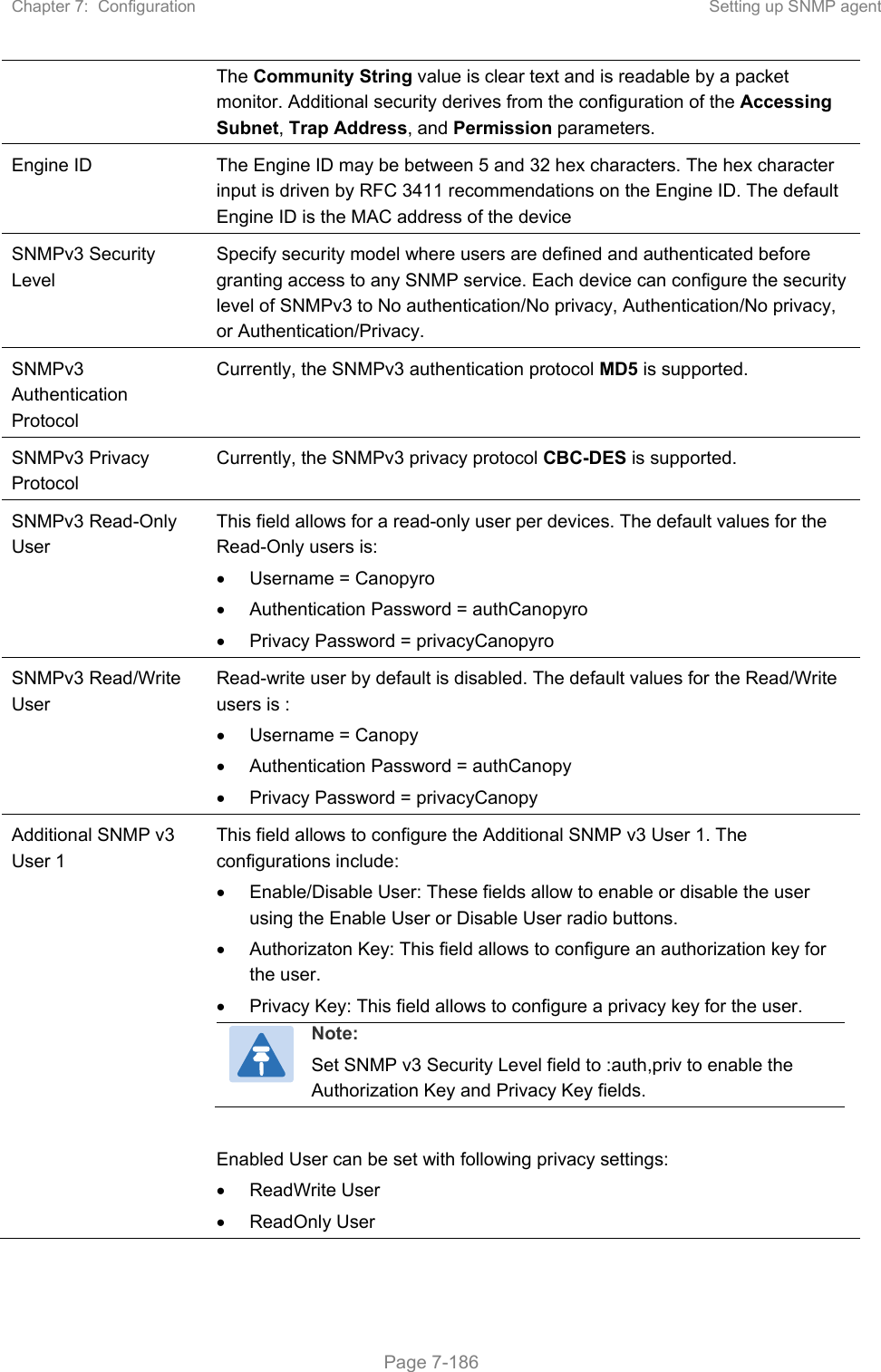
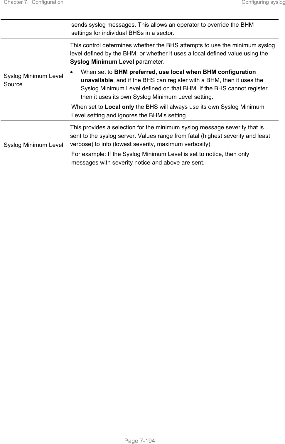
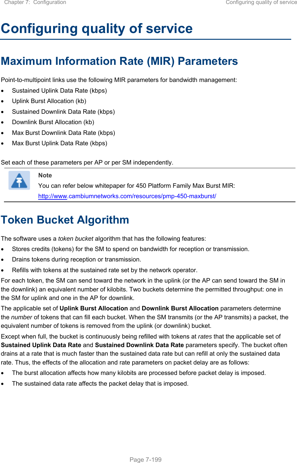
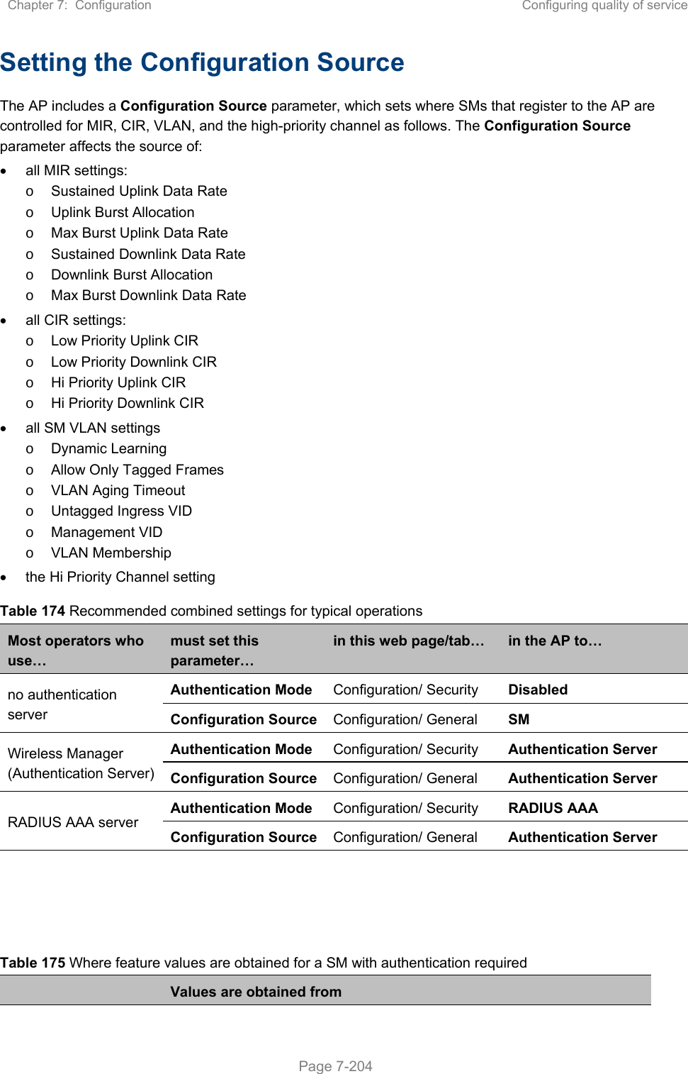
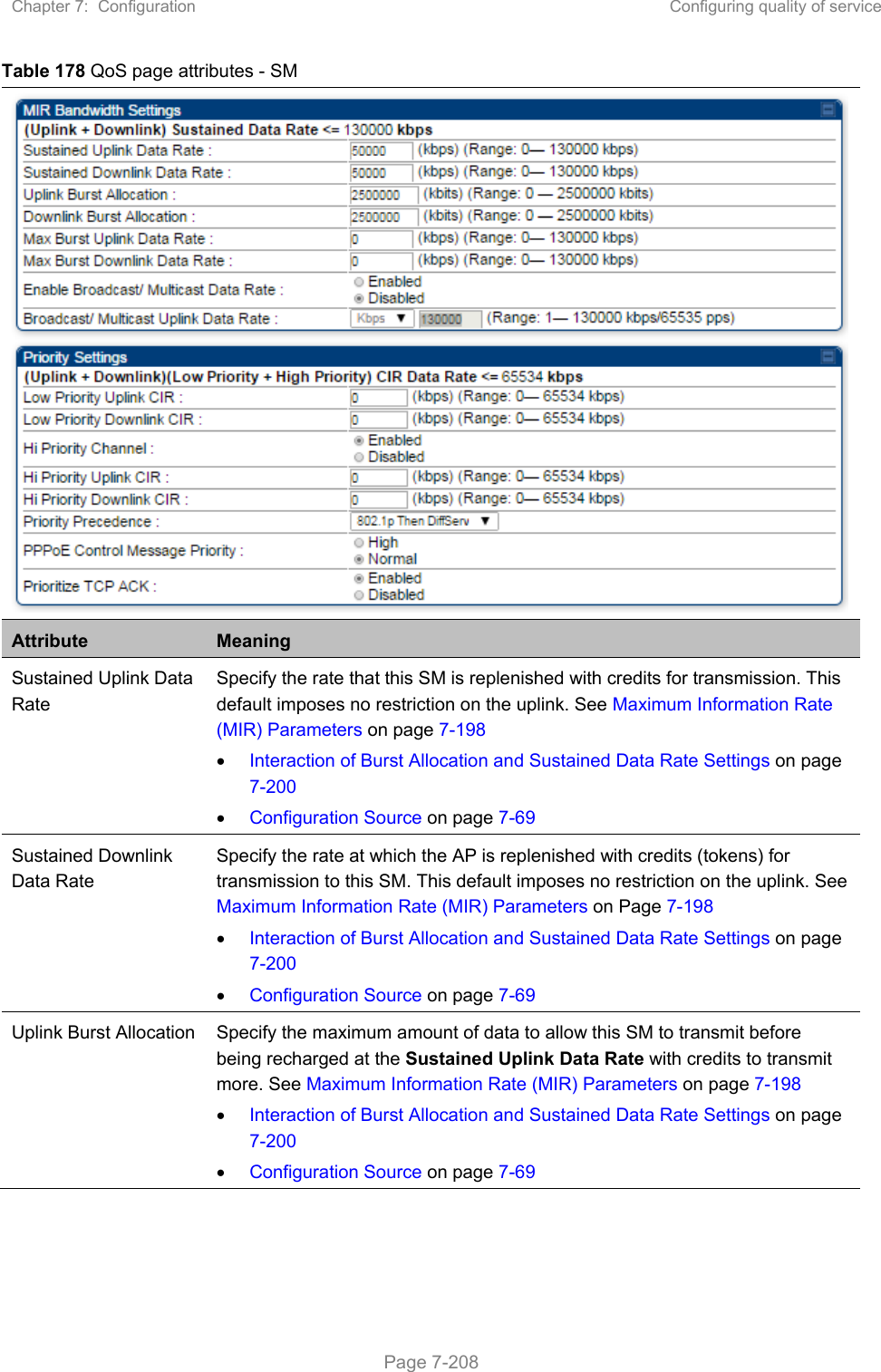
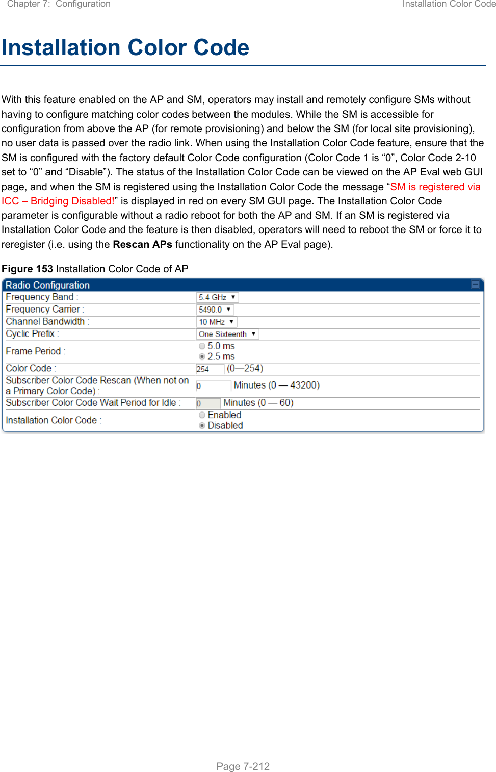
![Chapter 8: Tools Using the Link Status tool Page 8-46 Uplink Statistics – Signal to Noise Ratio This field represents the signal to noise ratio for the uplink (displayed when parameter Signal to Noise Ratio Calculation during Link Test is enabled) expressed for both the horizontal and vertical channels. Uplink Statistics – Link Test Efficiency This field displays the efficiency of the radio link, expressed as a percentage, for the radio uplink. Downlink Statistics – Beacon % Received Curr/Min/Max/Avg This field displays a count of beacons received by the SM in percentage. This value must be between 99-100%. If it is lower than 99%, it indicates a problematic link. This statistic is updated every 16 seconds. Downlink Statistics – Power Level: Signal Strength Ratio This field represents the received power level at the SM/BHS as well as the ratio of horizontal path signal strength to vertical path signal strength at the SM/BHS. Downlink Statistics – Signal to Noise Ratio This field represents the signal to noise ratio for the downlink (displayed when parameter Signal to Noise Ratio Calculation during Link Test is enabled) expressed for both the horizontal and vertical channels. Downlink Statistics – Link Test Efficiency This field displays the efficiency of the radio link, expressed as a percentage, for the radio downlink. Downlink Statistics – SU-MIMO Rate The SU-MIMO rate applies to all AP platforms. For 450m, this field indicates the rate being used for symbols where this particular VC is not being MU-MIMO grouped with other SMs. For 450 and 450i platforms, there is no grouping and this field indicates the modulation rate for all symbols. Downlink Statistics – MU-MIMO Rate The MU-MIMO rate applies only to the 450m AP. This field indicates the modulation rate used for symbols where this particular low priority VC is MU-MIMO scheduled by grouping it in the same slot with other low priority VC’s. BER Results This field displays the over-the-air Bit Error Rates for each downlink. (The ARQ [Automatic Resend 8-46equest] ensures that the transport BER [the BER seen end-to-end through a network] is essentially zero.) The level of acceptable over-the-air BER varies, based on operating requirements, but a reasonable value for a good link is a BER of 1e-4 (1 x 10⁻⁴) or better, approximately a packet resend rate of 5%. BER is generated using unused bits in the downlink. During periods of peak load, BER data is not updated as often, because the system puts priority on transport rather than on BER calculation. Reg Requests A Reg Requests count is the number of times the SM/BHS registered after the AP/BHM determined that the link had been down. If the number of sessions is significantly greater than the number for other SMs/BHS, then this may indicate a link problem (check mounting, alignment, receive power levels) or an interference problem (conduct a spectrum scan).](https://usermanual.wiki/Cambium-Networks/50450M.USERS-MANUAL-PART3/User-Guide-3650908-Page-151.png)