Cellphone Mate SureCall FORCE5-IS Industrial Booster User Manual

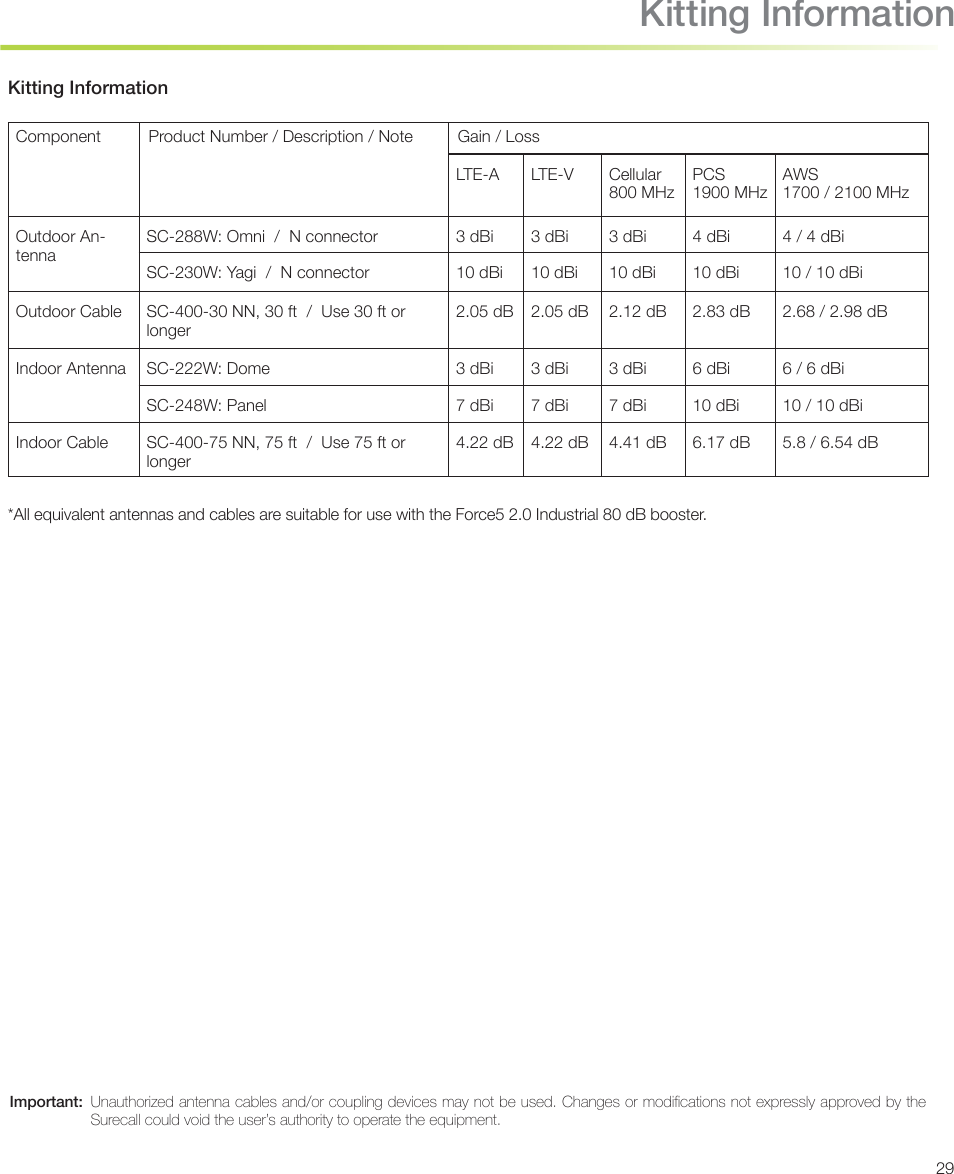
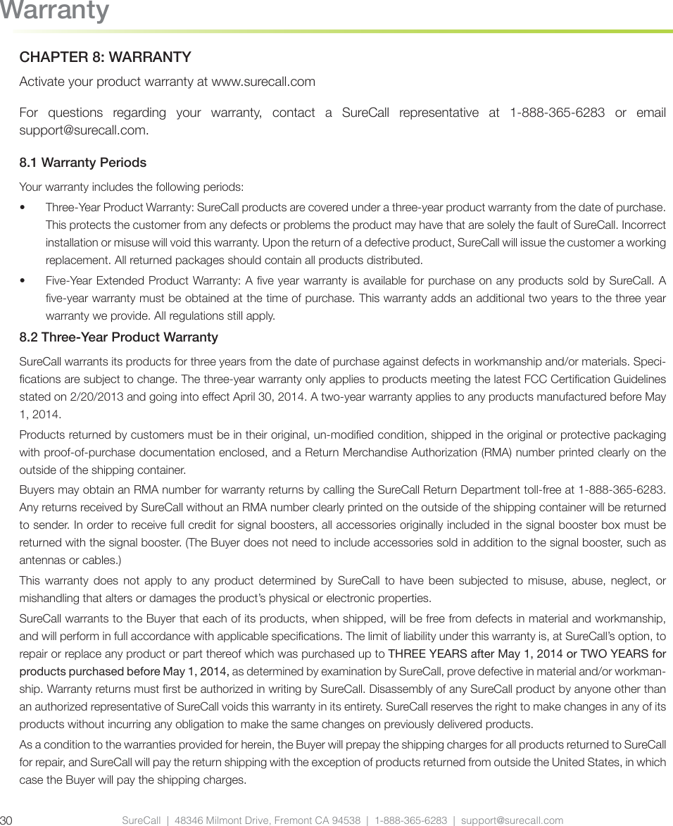
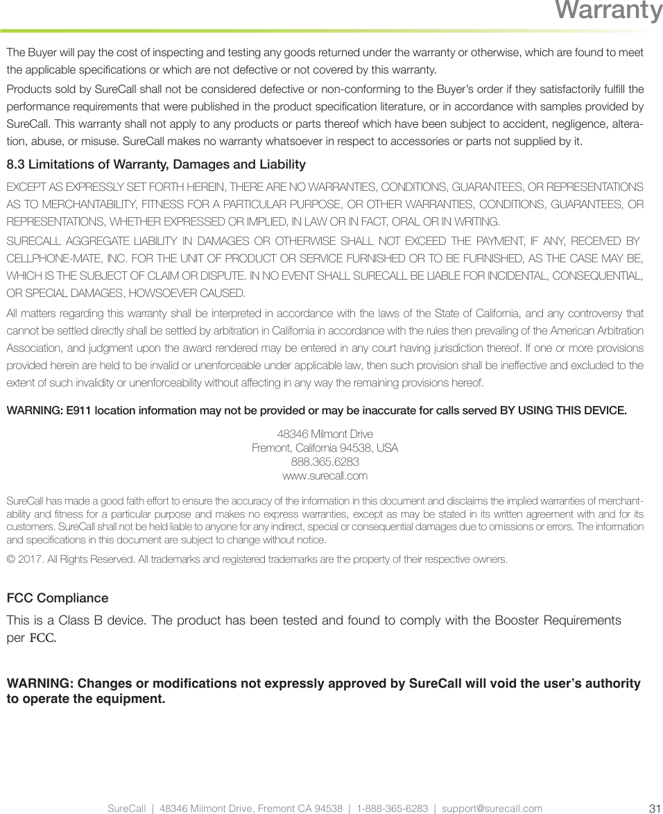
Cellphone-Mate Inc. dba SureCall Industrial Booster Users Manual

Users Manual

Force5™ 2.0 IndustrialCellular Signal Booster for voice and 4G data with Built-In Sentry MonitoringUser GuideWARNINGThis is NOT a CONSUMER device. It is designed for installation by FCC LICENSEES and QUALIFIED INSTALLERS. You MUST have an FCC LICENSE or the express consent of an FCC Licensee to operate this device. Unauthorized use may result in signicant forfeiture penalties, includ-ing penalties in excess of $100,000 for each continuing violation.
CONTENTSChapter 1: Introduction ............................................................................................................................................................ 31.1 Package Contents .....................................................................................................................................................................................31.2 Features & Benets ....................................................................................................................................................................................31.3 Additional Items Needed ............................................................................................................................................................................31.4 How Cellular Signal Boosters Work ............................................................................................................................................................4Chapter 2: Safety ..................................................................................................................................................................... 42.1 Safety Warnings ........................................................................................................................................................................................4Chapter 3: Planning The Installation ........................................................................................................................................ 63.1 Installation Overview ..................................................................................................................................................................................63.2 Exterior Antenna ........................................................................................................................................................................................73.3 Interior Antennas .......................................................................................................................................................................................83.4 Antenna Separation ...................................................................................................................................................................................93.5 Calculating Signal Strength ......................................................................................................................................................................103.6 Booster Location .....................................................................................................................................................................................123.7 Accessories .............................................................................................................................................................................................123.8 Need Help? .............................................................................................................................................................................................12Chapter 4. Installation ............................................................................................................................................................ 134.1 Soft Installation ........................................................................................................................................................................................134.2  Exterior Antenna .....................................................................................................................................................................................134.3 Interior Antennas .....................................................................................................................................................................................144.4 Mounting the BDA ...................................................................................................................................................................................15Chapter 5: Conguration & Testing ........................................................................................................................................ 165.1 Powering on the BDA ..............................................................................................................................................................................165.2 DIP Switch Conguration .........................................................................................................................................................................165.3. DIP Switch organization ..........................................................................................................................................................................175.4 LED Conditions .......................................................................................................................................................................................185.5 Testing & Troubleshooting ........................................................................................................................................................................19Chapter 6: Sentry Conguration............................................................................................................................................. 206.1 Software Installation .................................................................................................................................................................................206.2 Hardware Installation ...............................................................................................................................................................................206.3 User Registration .....................................................................................................................................................................................216.4 Device Registration ..................................................................................................................................................................................226.5 Device Conguration ................................................................................................................................................................................226.6 Using Antenna Placement Tool ................................................................................................................................................................256.7 Over Power Alert .....................................................................................................................................................................................26Chapter 7: Specications ....................................................................................................................................................... 28Chapter 8: Warranty ............................................................................................................................................................... 308.1 Warranty Periods .....................................................................................................................................................................................308.2 Three-Year Product Warranty ...................................................................................................................................................................308.3 Limitations of Warranty, Damages and Liability .........................................................................................................................................31FCC Compliance  ..........................................................................................................................................................................................31SureCall  |  48346 Milmont Drive, Fremont CA 94538  |  1-888-365-6283  |  support@surecall.com2Table of Contents
3IntroductionCHAPTER 1: INTRODUCTIONIntroducing SureCall’s Force5 2.0 Industrial Booster. Please read this entire manual before proceeding. 1.1 Package ContentsYour booster box contains the following items: •  (1) Force5 2.0 Industrial Booster and mounting kit•  (8) SC-222W Dome Antennas•  (1) 75 ft. Length of SC-400 Low Loss Cable•  (2) SC-WS-4 four-way splitters•  (1) SC-WS-2 two-way splitter•  (26) NC Connectors•  (1) Lightning protector (SC-LP)1.2 Features & BenetsThe booster oers the following features and benets:•  Five band signal booster that enhances cellular voice, text and 4G LTE signals•   Extends cellular signals in areas with poor coverage due to geographical location and/or building design•  Highly linear amplier producing the fastest 4G LTE data rates•  Powerful in-building booster with 31 dB of adjustable gain level•  Automatic oscillation detection and protection system powers down the booster to prevent harmful radio interference•  Maximum output power is 3 watts EIRP for Cellular, 2 watts EIRP for PCS and 1 watt for AWS 1710-1755 MHz bands. Fixed stations operating in the 1710-1755 MHz bands are limited to a maximum antenna height of 10 meters above ground1.3 Additional Items NeededThe booster requires the following additional components for a complete installation: •  An outside antenna, such as the SC-230W Yagi antenna or SC-288W omni antenna•  Sucient low loss 50 ohm interior/exterior cable•  Cable splitter if installing multiple antennas•   Multiple antennas (such as the SC-222W, omni-directional domes by SureCall)•  Grounded surge suppressor for DC power supply
SureCall  |  48346 Milmont Drive, Fremont CA 94538  |  1-888-365-6283  |  support@surecall.com41.4 How Cellular Signal Boosters WorkThe Force5 2.0 booster amplies cellular signals from the nearest tower to phones in a building and from those phones back to the tower to compensate for weak reception caused by distance, topography, building structure, among other reasons. The booster receives the signal from an outside antenna, amplies that signal and rebroadcasts it indoors via the interior antenna(s) where it is received by cellular devices. The interior antennas also pick up signals from cellular devices and pass them to the booster. The booster amplies these signals and passes them to the exterior antenna for rebroadcast back to the tower.CHAPTER 2: SAFETYThis chapter contains important safety information designed to prevent personal injury, equipment malfunction, and/or radio interference. You are responsible for ensuring a safe installation.2.1 Safety Warnings•   You are responsible for knowing and following all applicable codes and regulations and for obtaining all required permits and inspections.•  Follow all safety precautions contained in this Installation Manual.•   The installation process may require working in high locations such as roofs and/or ladders. Follow applicable safety regulations and  best  practices  to  injury.  Take care not to drop objects  o  any  high  area. Cordon  o ground areas directly below roof or ladder work.•   Always use appropriate personal protective equipment such as goggles, gloves, hard hat, etc. as needed or required.SafetyWARNING: FAILURE TO EXERCISE CAUTION WHEN WORKING IN HIGH AREAS COULD CAUSE A FALL AND PERSONAL INJURY.
5•   Some components may be heavy and/or bulky. Always use proper lifting and carrying techniques when handling components, especially when working on a ladder, roof, or other area with a fall hazard.•   The exterior antenna must not be co-located or operating in conjunction with any other antenna.•   Always use a properly installed SureCall lightning protector between the exterior antenna and the booster.•         Always power o the booster before working on the roof of the building or anywhere in close proximity to the external antenna.•   Allow at least 24 inches (60 cm) of separation between interior antennas and humans or animals.•  Allow at least 24 inches (60 cm) of separation between exterior antennas and all persons.•  Comply with all antenna separation requirements to prevent signal oscillation.CAUTION: SIGNAL OSCILLATION CAN CAUSE RADIO INTERFERENCE WITH CELLULAR TOWERS AND RESULT IN CIVIL AND/OR CRIMINAL PENALTIES.CAUTION: FAILURE TO PROPERLY INSTALL A LIGHTNING PROTECTOR CAN RESULT IN DAM-AGE TO THE BOOSTER, ANTENNAS, AND WIRING.Safety
SureCall  |  48346 Milmont Drive, Fremont CA 94538  |  1-888-365-6283  |  support@surecall.com6PlanningCHAPTER 3: PLANNING THE INSTALLATION3.1 Installation OverviewTypically, a BDA installation follows these steps:1.  Decide what type of exterior antenna to use, and where to mount it. You will use either an omnidirectional antenna, mounted vertically, or a directional Yagi antenna, pointed directly at the radio tower (line of sight). The antenna will normally be mounted on the roof of the building or wall with the strongest signal. A grounded lightning protector is required between the exterior antenna and the BDA.2.  Decide where to mount the interior antenna(s), being sure to take separation requirements into account. Long, narrow spaces benet most from directional at-panel antennas, while more square spaces benet more from omnidirectional dome antennas.3.  Decide where to mount the BDA. This should be in a secure indoor location near a grounded power source.4.  Decide where to route the cables between the exterior antenna and the BDA and between the BDA and interior antennas.5.  Install the antennas as described in their respective Installation Manuals.6.  Route the cables to the BDA location.7.  Install the BDA as described in this manual.8.  Power on the BDA and perform conguration and testing explained in Chapter 5.Important Installation Safety Precautions:CAUTION: FAILURE TO PROPERLY INSTALL A LIGHTNING PROTECTOR CAN RESULT IN DAMAGE TO THE BDA, ANTENNAS, AND WIRING.•  Some components may be heavy and/or bulky. Always use proper lifting and carrying techniques when handling components, especially when working on a ladder, roof, or other area with a fall hazard.•  The exterior antenna must not be co-located or operating in conjunction with any other antenna.•  Always use a properly installed SureCall lightning protector between the exterior antenna and the BDA.•  Always power o the BDA before working on the roof of the building, or anywhere in close proximity to the external antenna.
7Planning•  Allow at least 24 inches (60cm) of separation between interior antennas and humans or animals.•  Allow at least 24 inches (60cm) of separation between exterior antennas and all persons.•  Comply with all antenna separation requirements to prevent signal oscillation.CAUTION: SIGNAL OSCILLATION CAN CAUSE RADIO INTERFERENCE WITH RADIO TOWERS AND RESULT IN CIVIL AND/OR CRIMINAL PENALTIES.3.2 Exterior AntennaYou  may  use  either  an  omnidirectional antenna  that  covers  at  areas with  no  obstructions  or  a  directional  Yagi antenna to point directly at the tower. The omnidirectional antenna receives and transmits signals over a horizontal 360-degree circle. The Yagi antenna receives and transmits signals over a focused area and must be aimed directly (line of sight) toward the radio tower that provides the strongest signal to the building.The exterior antenna and mast (if any) must be mounted in a location that meets all of the following criteria:•  Best signal strength.•  Not co-located with other antennas or used in conjunction with other antennas.•  Away from all power lines.•  At least 6 ft. from lightning rod antennas.•  At least 24 in. from any person.
SureCall  |  48346 Milmont Drive, Fremont CA 94538  |  1-888-365-6283  |  support@surecall.com8Planning3.3 Interior AntennasYou may use any combination of omnidirectional (dome) and/or directional (at panel) interior antennas to obtain balanced signal strength throughout the structure.Dome  antennas  provide  360-degree  hemispherical  coverage  suitable  for  mostly  square  areas,  while  at  panel antennas provide a focused zone of coverage suitable for long narrow areas. The example above uses two dome antennas and one panel antenna to provide full coverageKeep in mind that oor structures in multistory buildings can cause signicant signal loss, which means that you may need to install interior antennas on more than one oor. Here is an example of a multistory installation:
SureCall  |  48346 Milmont Drive, Fremont CA 94538  |  1-888-365-6283  |  support@surecall.com SureCall  |  48346 Milmont Drive, Fremont CA 94538  |  1-888-365-6283  |  support@surecall.com 9Planning PlanningNote: You may not need antennas on every oor of a multistory building, depending on factors such as building material, BDA gain, etc.3.4 Antenna SeparationProper antenna separation prevents signal oscillation (feedback) that can interfere with the radio tower. Separa-tion is measured in a straight line from the exterior antenna to the closest interior antenna. The closest allowable distance depends on a number of factors, such as BDA gain level, building material, etc. Recommended separation distances are:Amplier gain Min. separation (ad)40 dB 5’-6’45 dB 15’-20’50 dB 50’55 dB 60’65 dB 75-80’70 dB 100’75 dB 100’-120’80 dB 120’-180’Vertical separation is more important than horizontal separation. If you are unable to obtain the required separation horizontally, try raising the exterior antenna. You may also try reducing the BDA gain as described in Chapter 5 of this manual.
SureCall  |  48346 Milmont Drive, Fremont CA 94538  |  1-888-365-6283  |  support@surecall.com10PlanningAntenna Safety Precautions:You can mix and match dome and directional antennas as needed to obtain proper coverage throughout the build-ing or area where you need to boost the signal. If you use a Yagi exterior antenna, you should normally aim it away from all interior antennas, regardless of separation, to prevent oscillation. 3.5 Calculating Signal StrengthYou can calculate the number of antennas you will need using the following parameters (in dB):•  Outside signal level (OSL): This is the signal strength at the exterior antenna location and will always be a negative number that will usually fall between -50 and -100 dBm. Calls will drop at levels of about -100 dB and lower. A system installed in an area where the signal is -85 or worse will require some detailed engineering to achieve an acceptable solution.•  Outside antenna gain (OAG): This is the signal boost provided by the exterior antenna and is always a positive number with SureCall antennas.SC-288W omni                           +3 OAG                                        GainCAUTION: SIGNAL OSCILLATION CAN CAUSE RADIO INTERFERENCE WITH RADIO TOWERS AND RESULT IN CIVIL AND/OR CRIMINAL PENALTIES.Antenna Aiming
11Planning•  Inside antenna gain (IAG): This is the signal boost provided by an interior antenna and is always a positive number with SureCall antennas.•  Cable loss (CL): This is the signal loss caused by the cable and is always a negative number.•  Splitter loss (SL): This is the signal loss caused by a splitter (used if you are installing multiple antennas).•  Booster gain (AG): Number of decibels of amplication provided by the booster (rated gain less any attenuation, as described in Chapter 5 of this manual). This is always a positive number. The signal strength S at an interior antenna equals OSL+OAG+IAG+CL+SL+AG. 2-way                                              -3                                3-way                                              -5      4-way                                              -6 SL           LossSC-222W omni dome              +3              IAG    Gain20 ft. SC-400      -1 dB / -2 dB30 ft. SC-400      -2 dB / -4 dB              50  ft.  SC-400      -3  dB /  -6 dB               100 ft. SC-400      -4 dB / -8 dB          CL           Loss
SureCall  |  48346 Milmont Drive, Fremont CA 94538  |  1-888-365-6283  |  support@surecall.com12Planning3.6 Booster LocationSelect an indoor location for the BDA that meets the following criteria:•  Wall or ceiling mounts are both acceptable.•  Near a properly grounded 110VAC outlet.•  Avoid in a tightly enclosed or overly hot spaces.•  All power and warning lights are easily visible.•  You can use the shortest cables to connect all antennas.3.7 AccessoriesThe nal step in the planning process is to make sure you have all of the necessary accessories to complete the installation. You will need all of the items listed in Chapter 1 of this manual plus some or all of the following:•  Cable clips: Use these to secure the cables to interior and exterior walls/ceilings.•  Appropriately rated sealant/caulking: Use this to waterproof the opening where the cable from the exterior antenna enters the building, if needed.•  Hand and/or power tools: As needed to complete the installation.•  Personal Equipment (PPE): Use all PPE required by local codes and/or best practices to help ensure personal safety during installation.Note: You may need to obtain a permit from your local building department to install the BDA and antennas. Check your local building and/or electrical codes.3.8 Need Help?If you need help planning your installation, contact a qualied installer, the reseller who supplied you with the BDA, or SureCall:Call: 1-888-365-6283, 7 a.m. to 5 p.m. PST, Monday – FridayEmail: support@surecall.comCAUTION: YOU ARE RESPONSIBLE FOR ENSURING THAT THE INSTALLATION MEETS ALL APPLICABLE CODES.
SureCall  |  48346 Milmont Drive, Fremont CA 94538  |  1-888-365-6283  |  support@surecall.com SureCall  |  48346 Milmont Drive, Fremont CA 94538  |  1-888-365-6283  |  support@surecall.com 13InstallationCHAPTER 4. INSTALLATION4.1 Soft InstallationPerform a “soft” installation of all components to test signal coverage and oscillation before making the installation permanent. Avoid making holes or other permanent attachments during this phase. Refer to Chapter 5 for conguration and testing instructions. Proceed with nal installation once conguration and testing are complete.4.2  Exterior AntennaMount the exterior antenna in the location you selected during the planning process. Be sure to follow all of the instructions included with the antenna to ensure a safe installation. Remember:•  An omni-directional antenna (e.g., SC-288W) must be mounted vertically.•  A directional Yagi antenna (e.g., SC-230W) must be mounted horizontally and be aimed at the desired cellular tower (line of sight)•  Mount the antenna.•  Connect a length of cable to the antenna and tighten.•  Run the cable along the planned route.•  Install a properly grounded SC-LP lightning protector.•  Seal any holes you make in the outside of the building with caulking or sealant.WARNING: FAILURE TO EXERCISE CAUTION WHEN WORKING IN HIGH AREAS COULD CAUSE A FALL AND PERSONAL INJURY.WARNING: DO NOT TOUCH ANY LIVE ELECTRICAL WIRES OR ALLOW THE ANTENNA OR CABLING TO TOUCH ANY LIVE ELECTRICAL WIRES.CAUTION: AVOID AIMING A YAGI ANTENNA TOWARD ANY INTERIOR ANTENNA.
SureCall  |  48346 Milmont Drive, Fremont CA 94538  |  1-888-365-6283  |  support@surecall.com14Installation4.3 Interior AntennasMount the interior antenna(s) in the location(s) you selected when planning. Follow all instructions included with the antenna(s) to ensure the installation(s) are implemented properly. Here are a few reminders and essential steps:•  Dome antennas are mounted on the ceiling as close to the center of the desired coverage area as possible, domed (convex) side pointing down.•  Flat panel antennas should be wall-mounted as close as possible to the center of the wall, or at one end of long narrow space.•  Mount the antenna(s).•  Connect a length of cable to the antenna and tighten.•  For multiple antennas, run the cable to the splitter location and connect the cable to one of the outputs on the splitter.•  Connect another length of cable to the input side of the splitter (if used) and run this cable to the BDA location.•  It is important to keep the cable runs equal or use taps to ensure a harmonious install.CAUTION: VERIFY THAT ALL INTERIOR ANTENNAS MEET THE SEPARATION REQUIREMENTS DESCRIBED IN THE PREVIOUS CHAPTER, AND THAT NO ANTENNA IS AIMED TOWARD THE EXTERIOR ANTENNA.CAUTION: DO NOT CONNECT AN INTERIOR ANTENNA TO THE SPLITTER INPUT.
SureCall  |  48346 Milmont Drive, Fremont CA 94538  |  1-888-365-6283  |  support@surecall.com SureCall  |  48346 Milmont Drive, Fremont CA 94538  |  1-888-365-6283  |  support@surecall.com 15 Installation4.4 Mounting the BDAMount the booster as follows:•  Verify that the selected location meets all criteria described in the previous chapter.•  Attach the included mounting kit to the booster using the screws provided. Tighten the screws by hand with a screwdriver until tight plus 1/4 to 1/2 turn. Do not over-tighten.•  Mount a 24 inch x 24 inch x 3⁄4 inch thick sheet of plywood on top of sheetrock, secured into wall studs where the booster is to be placed. The plywood should be ush against wall. •  Once the plywood is secure, attach booster to the plywood base using the screws provided. In most installa-tions, the housing will be oriented so the I/O ports are facing down.•  Connect the outdoor antenna cable to the signal booster connector port marked OUTSIDE and tighten the connection.•  Connect the outdoor antenna cable to the signal booster connector port marked INSIDE and tighten the connection.CAUTION: DO NOT POWER ON THE BDA UNTIL  INSTRUCTED TO DO SO.CAUTION: NEVER POWER ON THE BDA WHEN ANY ANTENNAS ARE DISCONNECTED AS THIS COULD DAMAGE THE BDA.
SureCall  |  48346 Milmont Drive, Fremont CA 94538  |  1-888-365-6283  |  support@surecall.com16InstallationCHAPTER 5: CONFIGURATION & TESTING5.1 Powering on the BDATo power on the booster:1.  Make sure that exterior and interior antenna cables are rmly connected to the proper ports on the booster.2.  Plug a surge suppressor into a grounded 110 VAC wall outlet.3.  Plug the AC end of the supplied power adapter into the surge suppressor.4.  Plug the DC end of the power adapter into the Power port on the booster.5.  Verify that the green Power light is illuminated.6.  When the booster is turned on, the band lights will ash red and yellow for approximately 10 seconds.CAUTION: ONLY USE THE POWER SUPPLY INCLUDED WITH THE BDA. USE OF ANOTHER POWER SUPPLY COULD DAMAGE THE BDA AND/OR POWER SUPPLY.CAUTION: DO NOT PROCEED BEYOND THIS POINT UNTIL THE BDA IS POWERED ON AND NO RED WARNING LIGHTS ARE ILLUMINATED.5.2 DIP Switch CongurationBy default, your booster ships with all DIP switches turned OFF to provide maximum gain in all channels. This should always be your starting point whenever installing or reinstalling the booster. When the booster is turned on, the band lights will ash red and yellow for approximately 10 seconds. The following diagrams and notes explain how to interpret, and use, these switch banks.
175.3. DIP Switch organization1.  LTE-UL AT&T (707 MHz) DIP switches control LTE uplink (switch 1-5)2.  LTE-DL (728-757 MHz) DIP switches control LTE downlink (switch 1-5)3.  LTE-UL Verizon (781 MHz) DIP switches control LTE uplink (switch 1-5)4.  CELLULAR-UL (800 MHz) DIP switches control Cellular uplink (switch 1-5) 5.  CELLULAR-DL (800 MHz) DIP switches control Cellular downlink (switch 1-5)6.  PCS-UL (1900 MHz) DIP switches control PCS uplink (switch 1-5)7.  PCS-DL (1900 MHz) DIP switches control PCS downlink (switch 1-5)8.  AWS-UL (2100 MHz) DIP switches control AWS uplink (switch 1-5)9.  AWS-DL (2100 MHz) DIP switches control AWS downlink (switch 1-5)  Switches should be OFF unless red ashing lights occur for a channel or channels. Red ashing lights indicate the system has detected oscillation for the corresponding channel(s). They then turn o if adjustments are not made. When adjusting the booster, full power is not always the best option. Your goal is to obtain a usable signal in as many areas of the building as possible.UPLINKDOWNLINK124 816124 8161  2  3  4  5PS-ULPS700-DL1 2 4 8 161 2 4 8 161  2  3  4  5Switch 1    Switch 2       Switch 3       Switch 4      Switch 5  1 dB            2 dB             4 dB              8 dB           16 dBAdditive combination eects:•  Switch 1 (1 dB) + Switch 2 (2 dB) = 3 dB attenuation•  Switch 1 (1 dB) + Switch 2 (2 dB) + Switch 3 (4 dB) = 7 dB attenuation•  Switch 1 (1 dB) + Switch 2 (2 dB) + Switch 3 (4 dB) + Switch 4 (8 dB) = 15 dB attenuation•  Switch 1 (1 dB) + Switch 2 (2 dB) + Switch 3 (4 dB) + Switch 4 (8 dB) + Switch 5 (16 dB) = 31 dB attenuationConguration and Testing
SureCall  |  48346 Milmont Drive, Fremont CA 94538  |  1-888-365-6283  |  support@surecall.com18A few practical examples: •  Turning all switches OFF = 0 dB attenuation (booster is at full gain).•  Turning ON switch #1 in a bank = 1 dB attenuation (booster maximum gain is reduced by 1 dB).•  Turning ON switches #1, 3, and 5 in a bank = 1+4+16 dB attenuation = 21 dB attenuation. For example, in an 80 dB booster, the selected channel is reduced to 59 dB (80 dB -21 dB).•  Turning ON all switches in a bank = 1+2+4+8+16 dB attenuation = 31 dB attenuation. For example, in an 80 dB booster, the selected channel is reduced to 49 dB (80 dB-31 dB).When the booster is powered on, the green Power light should illuminate.•  If any of the bands are oscillating, the corresponding band lights will ash red and the corresponding band(s) will shut o.Note: When the booster is turned on, the band lights will ash red and yellow for approximately 10 seconds.Note: In general, the uplink and downlink DIP switches should be set identically but this is not always the case.5.4 LED ConditionsThis section will help you interpret the LED indicators on your Force5 2.0. But rst, here are a few conguration and testing points to keep in mind:•  When choosing a location for the outside antenna, a minimum signal reading of –100 dB is needed. A signal in the -70 dB to -90 dB range is recommended for best performance. A signal stronger than -70 dB may cause the aected frequency bands to stop amplifying.•  The booster gain dials should be at maximum level unless the control light for a specic frequency band is ashing red or red-yellow. In either case, try increasing the antenna separation between the inside and outside antennas as much as possible rst, and then restarting the booster.•  Avoid setting the gain below 35 dB, as this could cause the aected frequency band to stop amplifying.Conguration and Testing
19Conguration and TestingLED INDICATIONSLEDColorLEDConditionResolutionYellow Solid The frequency band is not in use. Eventually, the band will enter sleep mode. When the light is o, it means things are normal, and that the band is active.Yellow Flashing The Automatic Gain Control (AGC) is self-adjusting. This occurs during normal operation.Red Flashing The booster is receiving too much signal. Can cause the aected band to automatically turn o. If this happens:1.  For kits using an OMNI outside antenna, relocate the outside antenna to a location where the signal is weaker.2.  For kits using a YAGI outside antenna, turn the antenna in short increments away from the signal source.3.  Increase the separation between antennas (more vertical separation works best).4.  Add an inline attenuator to the cable connected to the Outside port on the booster.Red Solid The associated frequency band is o. If the red light ashes for a long time (caused by too much signal), and then turns solid red, it means the associated frequency band has been turned o. This will happen if the gain dial for that frequency band has been turned all the way down.Yellow/ RedFlashes alternat-ing colorsSelf-oscillation has been prevented. Try this:1.  Increase the separation between the inside and outside antennas. If your booster kit uses two directional antennas (example: outside Yagi antenna and inside panel antenna), ensure that they are facing away from each other.2.  If the condition continues, lower the dB gain setting in small increments until the light turns o or ashes yellow.Refer to your Sentry Monitoring Software for more information about LED codes. Meanwhile, if you have any questions during setup, please reach out to our U.S.-based support technicians:Call: 1-888-365-6283Email: support@surecall.com5.5 Testing & TroubleshootingOnce the booster is powered on (and no Warning lights are on), walk around the area to assess the voice and/or data signal in representative variety of locations. Rene the antenna locations and/or gain levels as needed, and then complete the permanent installation when you are condent the system will perform well.A few tips and some perspective:•  It’s not realistic to expect full reception everywhere in the building.•  As a general rule, increasing gain by 6 dB doubles the coverage distance of the interior antennas. Start at the lowest gain and increase gradually as needed.•  If one or more red Warning lights comes on, it indicates there is oscillation in that band and adjustments are needed.•  If you can’t get the coverage reasonably well-balanced, you may need to install an additional interior antenna and/or a dierent type of interior antenna and/or relocate interior antennas.
SureCall  |  48346 Milmont Drive, Fremont CA 94538  |  1-888-365-6283  |  support@surecall.com20 Sentry Conguration & MonitoringCHAPTER 6: SENTRY CONFIGURATIONSentry Software IntroductionSureCall’s Sentry is a revolutionary advancement in signal-booster management. It aids in the installation, optimi-zation, and ongoing management of your Force5 2.0 BDA. It provides installers with tools for seamless system congurations, and it helps pinpoint malfunctions due to unforeseen changes in the amplier landscape, such as new towers or repeater systems. Sentry also noties installers or end users about various parameters via email. Features include:•  Quick notication about booster changes and over-power situations.•  Allows osite monitoring and adjustments related to booster performance, such as uplink, downlink or bands.•  Helps optimize installations by monitoring and identifying the strongest signal strength available.6.1 Software InstallationTo install and congure the server, follow these steps:•  Get the SureCall Sentry software from your device supplier, or download the Windows software here: http://www.surecall.com/product/Sentry.html.•  Install the software using the steps outlined below. •  Congure the server to a static IP or public IP address. •  In order to function on the network correctly, the server and the Force5 2.0 device must be (a) on the same Local Area Network, or (b) the server must be the front end to the device.•  Use appropriate security software for safe and reliable operation when connected to a network.•  All device and user information will be stored on the computer.Double-click ServerSentrySetup(V1.5).exe to start the installation, which takes you to Welcome screen.Note: To avoid install glitches, we recommend you close all other Windows programs running on your computer before proceeding.After you have shut down other programs, click Next, which will take you to the User Information screen shown below. This is where you’ll enter user information. It may be you as the installer, or you may be setting this up for someone else who will be monitoring the system on an ongoing basis.6.2 Hardware InstallationOnce the Sentry software is installed, you can proceed to connect and congure the Force5 2.0 BDA. •  Connect the USB cable (provided) to the Booster’s USB port then connect the other end of the USB cable to the USB port on your computer. The USB is only needed for conguration and may be disconnected once complete.
21•  Connect an Ethernet cable to the booster's WAN port and connect the other end to your router.•  Once the connections are made, power on the Force5 2.0 BDA.•  Start the Sentry client application software. You will see the screens below:6.3 User RegistrationYou’ll need to register an account. Connect your computer to the network. A secure LAN connection is important because it will allow the computer to “see” the device on the network. Fill in the User Registration form and choose a user name, password, email and user phone. Once completed, click the Register button.Conguration and Testing Sentry Conguration & MonitoringClick Register and you’ll see the following screen, prompting you to enter the local Server IP address.Enter SureCall’s server IP: 99.55.251.45 in the Registration Window.Enter a User Name, Password, E-mail, and User Phone  in  the  elds  provided.  Then  click  Register  to proceed. You will the Login screen again, as shown in the next screen.In  the  elds  provided,  enter  the  Username  and Password that you registered on the system. This will  enable  you  to  proceed  to  device  conguration, as explained in the steps below:
SureCall  |  48346 Milmont Drive, Fremont CA 94538  |  1-888-365-6283  |  support@surecall.com22 Sentry Conguration & Operation6.4 Device RegistrationConnect the device to the networked client computer with a USB cable as described in the previous section. Make sure the server is also linked to the computer. Select a serial port and click Open, as shown in the Add Booster screen below. Complete device registration as described below:•  Click Refresh to query device parameters•  Enter a name in the Booster Name eld•  Enter  the  location  in  the  Location  Address  eld (optional)•  Click Add to register the device on the server•  Keep in mind that only the registered user is authorized to see/operate the added device.6.5 Device CongurationUsing the same screen as before, congure the device according to the steps below.•  Select a serial port and click Open.•  Click Refresh to query device parameters.•  Click on the drop-down menu and select a server IP address and port number to make sure the device can be connected to the server.•  Dynamic IP is available by checking Auto Search IP function, OR…•  …OR enter IP parameters manually, if the device needs a static IP.•  Click Apply to nish the conguration.The following summary screen appears if the booster connects to the server successfully:
23 Sentry Conguration & OperationColumn Denitions:•  Attenuation: Manually adjusted attenuation via software.•  Manual Attenuation: Manually adjusted attenuation using controls on the device.•  Automatic Gain Control: Automatically adjusted attenuation from excessive signal or close indoor/outdoor antenna proximity•  Gain: Current gain.•  Output Power: Current power.•  Outside Signal Strength: Strength of input signal.•  Uplink/Downlink Status: RF band status: Sleep, Active, OFF.•  Over Power: Over-power alert status: Red=Alert; Green=Normal.•  Oscillation: Oscillation-alert status: Red=Alert; Green=Normal.•  Over Attenuation: Manual over-attenuation status: Red=Alert; Green=Normal.NOTE: BOTH THE MANUALLY ADJUSTED ATTENUATION BY DEVICE AND BY SOFTWARE CANNOT EXCEED 25 DB.
Modify Booster Information. To modify the booster information, right click to access a pop-up menu with the follow-ing additional options. Select Edit Booster Info to proceed.Delete Booster. To delete a booster, right click on the summary screen again to access a pop-up menu with additional options, and then select Delete Booster.You will see a conrmation screen as shown below. Click Yes to proceed.Password and E-mail Management: In the Tools pull-down menu, you can change your account information, includ-ing your password, or the e-mail address for status reports. Roll over the Accounts heading and click on Modify Password/E-mail to access this feature.SureCall  |  48346 Milmont Drive, Fremont CA 94538  |  1-888-365-6283  |  support@surecall.com24Sentry Operation
To modify your password, type in the requested information shown below and click on Modify.To change the e-mail address where alerts go, enter a new e-mail as shown above and click on Modify.NOTE: IF YOU FORGET YOUR PASSWORD, CLICK FORGOT MY PASSWORD ON THE LOGIN PAGE. THE PASSWORD WILL BE SENT TO YOUR E-MAIL ADDRESS.6.6 Using Antenna Placement ToolAntenna Position Debug: The Antenna Position Debug Tool is used to test antenna RSSI values that will help you locate the optimal installation position of the outdoor antenna. Select your device, and right click to access a pop-up menu with additional options as shown below. Select Antenna Position Debug.25 Sentry OperationYou will see the following Debug Tool screen:
Email Alerts Email alerts will be sent in the event of booster overpowering, over-attenuation, or if oscillation is detected. SureCall  |  48346 Milmont Drive, Fremont CA 94538  |  1-888-365-6283  |  support@surecall.com26Sentry OperationThis tool will identify the optimum location for the outdoor antenna.  To test for the best location, the booster and outside antenna must be connected by coax cable. Place the antenna in a position you’d like to test and click on the measure button.The “Position” elds will automatically populate with the dB measurement from various locations by clicking on the measure button at each possible location. You can test up to 5 positions. Once you have entered all locations, click on the “Compare” button to nd the best location. Keep in mind that a signal of less than -65 dB can over-power the booster. 6.7 Over Power AlertIf Red=ON, it means the input signal is too strong. Here are four possible solutions to try:1.  Relocate the outdoor antenna to a location where the signal is weaker. Or, If using a Yagi outside antenna, turn in small increments away from cell tower until Red alert is resolved.2.  Add an inline 5 dB or 10 dB attenuator (parts: SC-ATNR-5 and SC-ATNR-10) to the cable coming into the booster.3.  Lower the dB gain in small increments on the Sentry booster dashboard under the Attenuation column until the Over Power alert is resolved.4.  Manually adjust the attenuation or turn o a single band to mitigate oscillation and over-power issues.ATTENUATION THROUGH CLIENT SOFTWARE IS CUMULATIVE WITH THAT OF DIP SWITCHES.
Sentry OperationFrom the dashboard above you can manually adjust the attenuation dB to resolve problems with oscillation and overpowering issues. You can also turn o individual bands.ATTENUATION CAN BE LOWERED TO A MAXIMUM OF 30 OR 31 DB, DEPENDING ON THE BOOSTER MODEL AND A MAX OF 25 DB THROUGH SENTRY SOFTWARE. Sentry Dashboard27
Force5 2.0 Industrial SpecicationsUplink Frequency Range (MHz): 698–716 / 776–787 / 824–849 / 1850–1915 / 1710–1755 (G Block Included)Downlink Frequency Range (MHz): 728–746 / 746–757 / 869–894 / 1930–1995 / 2110–2155 (G Block Included)Supported Standards: CDMA, WCDMA, GSM, EDGE, HSPA+, EVDO, LTE and all cellular standardsInput / Output Impedance: 50 Ω Maximum Gain: 80 dB Noise Figure: 5 dBVSWR: ≤2.0AC Input / Output: Input AC 110 V, 60 Hz  /  Output DC 19 VMaximum Output Power: 3 Watt EIRPCable: SC-400 (not provided)RF Connectors: N Female (both)Power Consumption: <65WOperation Temperature: -4º F to +158º FDimensions: 14.5 x 11 x 3.5 inchesWeight: 19.5 lbsFCC ID RSNFORCE5-ISCHAPTER 7: SPECIFICATIONSSureCall  |  48346 Milmont Drive, Fremont CA 94538  |  1-888-365-6283  |  support@surecall.com28Specications
Kitting InformationComponent Product Number / Description / Note Gain / LossLTE-A LTE-V Cellular  800 MHzPCS  1900 MHzAWS  1700 / 2100 MHzOutdoor An-tennaSC-288W: Omni  /  N connector 3 dBi 3 dBi 3 dBi 4 dBi 4 / 4 dBiSC-230W: Yagi  /  N connector 10 dBi 10 dBi 10 dBi 10 dBi 10 / 10 dBiOutdoor Cable SC-400-30 NN, 30 ft  /  Use 30 ft or longer2.05 dB 2.05 dB 2.12 dB 2.83 dB 2.68 / 2.98 dB Indoor Antenna SC-222W: Dome   3 dBi 3 dBi 3 dBi 6 dBi 6 / 6 dBiSC-248W: Panel 7 dBi 7 dBi 7 dBi 10 dBi 10 / 10 dBiIndoor Cable SC-400-75 NN, 75 ft  /  Use 75 ft or longer4.22 dB 4.22 dB 4.41 dB 6.17 dB 5.8 / 6.54 dB*All equivalent antennas and cables are suitable for use with the Force5 2.0 Industrial 80 dB booster.Kitting InformationImportant:      Unauthorized antenna cables and/or coupling devices may not be used. Changes or modications not expressly approved by the Surecall could void the user’s authority to operate the equipment. 29
CHAPTER 8: WARRANTYActivate your product warranty at www.surecall.comFor questions regarding your warranty, contact a SureCall representative at 1-888-365-6283 or email support@surecall.com.8.1 Warranty PeriodsYour warranty includes the following periods:•  Three-Year Product Warranty: SureCall products are covered under a three-year product warranty from the date of purchase. This protects the customer from any defects or problems the product may have that are solely the fault of SureCall. Incorrect installation or misuse will void this warranty. Upon the return of a defective product, SureCall will issue the customer a working replacement. All returned packages should contain all products distributed.•  Five-Year Extended Product Warranty: A ve year warranty is available for purchase on any products sold by SureCall. A ve-year warranty must be obtained at the time of purchase. This warranty adds an additional two years to the three year warranty we provide. All regulations still apply. 8.2 Three-Year Product WarrantySureCall warrants its products for three years from the date of purchase against defects in workmanship and/or materials. Speci-cations are subject to change. The three-year warranty only applies to products meeting the latest FCC Certication Guidelines stated on 2/20/2013 and going into eect April 30, 2014. A two-year warranty applies to any products manufactured before May 1, 2014.Products returned by customers must be in their original, un-modied condition, shipped in the original or protective packaging with proof-of-purchase documentation enclosed, and a Return Merchandise Authorization (RMA) number printed clearly on the outside of the shipping container. Buyers may obtain an RMA number for warranty returns by calling the SureCall Return Department toll-free at 1-888-365-6283. Any returns received by SureCall without an RMA number clearly printed on the outside of the shipping container will be returned to sender. In order to receive full credit for signal boosters, all accessories originally included in the signal booster box must be returned with the signal booster. (The Buyer does not need to include accessories sold in addition to the signal booster, such as antennas or cables.) This warranty does not apply to any product determined by SureCall to have been subjected to misuse, abuse, neglect, or mishandling that alters or damages the product’s physical or electronic properties.SureCall warrants to the Buyer that each of its products, when shipped, will be free from defects in material and workmanship, and will perform in full accordance with applicable specications. The limit of liability under this warranty is, at SureCall’s option, to repair or replace any product or part thereof which was purchased up to THREE YEARS after May 1, 2014 or TWO YEARS for products purchased before May 1, 2014, as determined by examination by SureCall, prove defective in material and/or workman-ship. Warranty returns must rst be authorized in writing by SureCall. Disassembly of any SureCall product by anyone other than an authorized representative of SureCall voids this warranty in its entirety. SureCall reserves the right to make changes in any of its products without incurring any obligation to make the same changes on previously delivered products. As a condition to the warranties provided for herein, the Buyer will prepay the shipping charges for all products returned to SureCall for repair, and SureCall will pay the return shipping with the exception of products returned from outside the United States, in which case the Buyer will pay the shipping charges. WarrantySureCall  |  48346 Milmont Drive, Fremont CA 94538  |  1-888-365-6283  |  support@surecall.com30
Warranty31The Buyer will pay the cost of inspecting and testing any goods returned under the warranty or otherwise, which are found to meet the applicable specications or which are not defective or not covered by this warranty. Products sold by SureCall shall not be considered defective or non-conforming to the Buyer’s order if they satisfactorily fulll the performance requirements that were published in the product specication literature, or in accordance with samples provided by SureCall. This warranty shall not apply to any products or parts thereof which have been subject to accident, negligence, altera-tion, abuse, or misuse. SureCall makes no warranty whatsoever in respect to accessories or parts not supplied by it.8.3 Limitations of Warranty, Damages and LiabilityEXCEPT AS EXPRESSLY SET FORTH HEREIN, THERE ARE NO WARRANTIES, CONDITIONS, GUARANTEES, OR REPRESENTATIONS AS TO MERCHANTABILITY, FITNESS FOR A PARTICULAR PURPOSE, OR OTHER WARRANTIES, CONDITIONS, GUARANTEES, OR REPRESENTATIONS, WHETHER EXPRESSED OR IMPLIED, IN LAW OR IN FACT, ORAL OR IN WRITING. SURECALL AGGREGATE LIABILITY IN DAMAGES OR OTHERWISE SHALL NOT EXCEED THE PAYMENT, IF ANY, RECEIVED BY CELLPHONE-MATE, INC. FOR THE UNIT OF PRODUCT OR SERVICE FURNISHED OR TO BE FURNISHED, AS THE CASE MAY BE, WHICH IS THE SUBJECT OF CLAIM OR DISPUTE. IN NO EVENT SHALL SURECALL BE LIABLE FOR INCIDENTAL, CONSEQUENTIAL, OR SPECIAL DAMAGES, HOWSOEVER CAUSED. All matters regarding this warranty shall be interpreted in accordance with the laws of the State of California, and any controversy that cannot be settled directly shall be settled by arbitration in California in accordance with the rules then prevailing of the American Arbitration Association, and judgment upon the award rendered may be entered in any court having jurisdiction thereof. If one or more provisions provided herein are held to be invalid or unenforceable under applicable law, then such provision shall be ineective and excluded to the extent of such invalidity or unenforceability without aecting in any way the remaining provisions hereof.WARNING: E911 location information may not be provided or may be inaccurate for calls served BY USING THIS DEVICE.48346 Milmont DriveFremont, California 94538, USA888.365.6283www.surecall.comSureCall has made a good faith eort to ensure the accuracy of the information in this document and disclaims the implied warranties of merchant-ability and tness for a particular purpose and makes no express warranties, except as may be stated in its written agreement with and for its customers. SureCall shall not be held liable to anyone for any indirect, special or consequential damages due to omissions or errors. The information and specications in this document are subject to change without notice. © 2017. All Rights Reserved. All trademarks and registered trademarks are the property of their respective owners.FCC Compliance This is a Class B device. The product has been tested and found to comply with the Booster Requirements per FCC.WARNING: Changes or modications not expressly approved by SureCall will void the user’s authority to operate the equipment.SureCall  |  48346 Milmont Drive, Fremont CA 94538  |  1-888-365-6283  |  support@surecall.com
SureCall, Inc48346 Milmont DriveFremont, California 94538, USA888.365.6283  |  www.surecall.com

Navigation menu