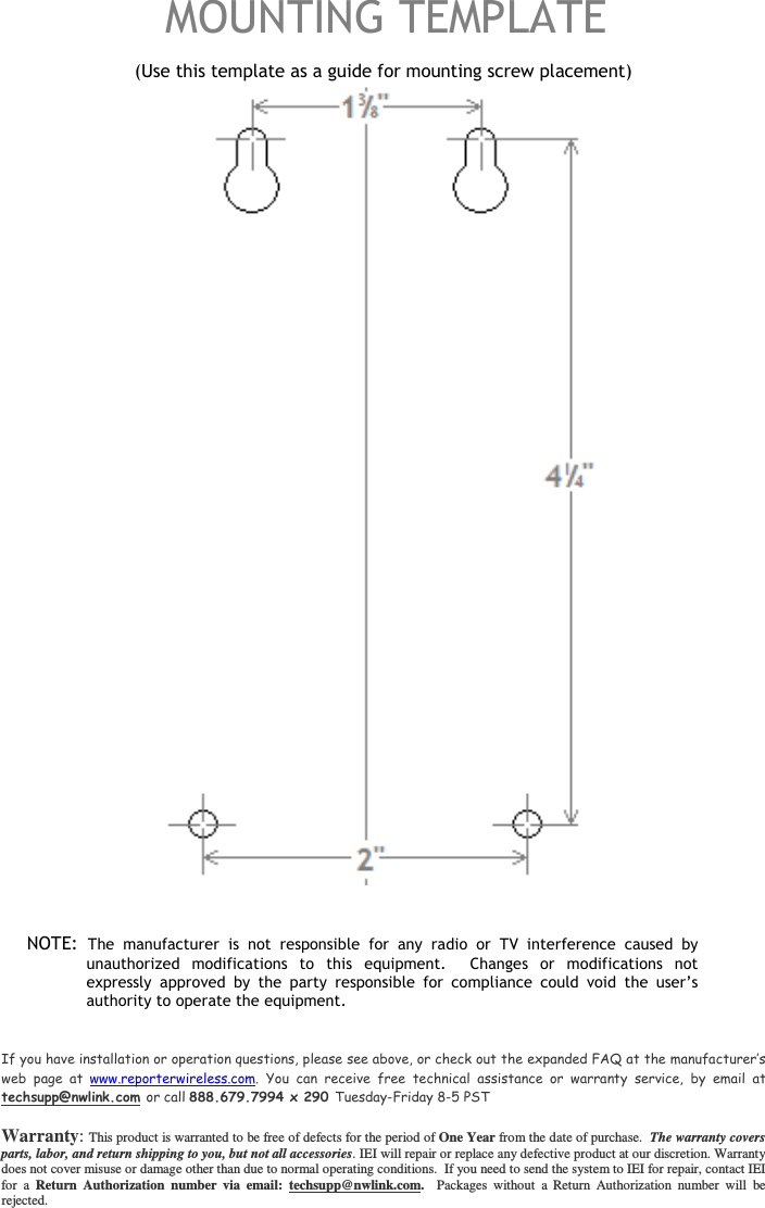
Chamberlain Wireless OMG2 MiniGap II User Manual MiniGAPII instructions

Chamberlain Wireless Products Inc. MiniGap II MiniGAPII instructions

Manual

MOUNTING TEMPLATE  (Use this template as a guide for mounting screw placement)                                                       NOTE: The  manufacturer  is  not  responsible  for  any  radio  or  TV  interference  caused  by unauthorized  modifications  to  this  equipment.    Changes  or  modifications  not expressly  approved  by  the  party  responsible  for  compliance  could  void  the  user’s authority to operate the equipment.    If you have installation or operation questions, please see above, or check out the expanded FAQ at the manufacturer’s web  page  at  www.reporterwireless.com.  You  can  receive  free  technical  assistance  or  warranty  service,  by  email  at techsupp@nwlink.com or call 888.679.7994 x 290 Tuesday-Friday 8-5 PST  Warranty: This product is warranted to be free of defects for the period of One Year from the date of purchase.  The warranty covers parts, labor, and return shipping to you, but not all accessories. IEI will repair or replace any defective product at our discretion. Warranty does not cover misuse or damage other than due to normal operating conditions.  If you need to send the system to IEI for repair, contact IEI for  a  Return  Authorization  number  via  email:  techsupp@nwlink.com.    Packages  without  a  Return  Authorization  number  will  be rejected.
          MiniGAP2                 System Features: • Easy to mount on any surface or in any location •  Weather Resistant Design •  Use Outside the Front door or for a side door •  Wireless Gate Access Control •  Up to Two Year battery life •  Secure digital connection •  Unlimited number of units can operate on a property, without interfering with other Intercom networks. Made With Pride In the USA. This product is covered by a manufacturer’s full One Year Warranty. FCC STATEMENT This device complies with FCC part 15 rules. It may not cause harmful interference with other devices, and must accept interference from other devices.  Thank  you  for  purchasing the Oracle MiniGAP2. This product  has  been  designed and  manufactured  in  the USA,  utilizing  the  highest quality standards available.  Model OMG2 102406 Patents pending  The  Oracle™  MiniGAP2  unit can be your primary door and gate  access  system  or  used as  an  accessory  to  a  Gate Access Panel (GAP).  For  privacy,  your  Oracle system  forms  an  exclusive network,  and  responds  only to  other  units  in  your network. (Patent Pending)  Since  this  MiniGAP2  Access and Intercom system requires no  connection  to  wall  power, it  is  perfect  for  remote locations.    Please read the instructions carefully.  Setting Up the MiniGAP2   Installation Make  sure  that  the  CALL  button is  in  easy reach of a visitor.   To  mount  the  MiniGAP2  with  four  screws, use  the  included  mounting  template  (see Back Page) as a guide for screw placement.  Tighten the top two screws halfway.  Place the  back  of  the  MiniGAP2  on  the  two  top screws  and  tighten.  Put  the  other  two screws in the bottom holes and tighten. Note:    Do  not  assemble  the  front  of  the unit until it has been activated.   Use  the  double-sided  mounting  tape  to mount  the  MiniGAP2  on  a metal,  glass,  or other  smooth  surface  where  you  wouldn’t want to use screws.   Note:  For  best  results,  clean  both surfaces  that  the  double-sided mounting  tape will  be  in  contact with,  using  the  included  alcohol wipe.   Peel  the  protective  paper  off  of  the mounting tape and firmly press it onto the back  of  the  MiniGAP2.  Press  firmly  on  the back  of  the  tape  to  push  out  any  trapped air bubbles. When ready to do so, peel the red  protective  paper  from  the  mounting tape  and  firmly  press  the  MiniGAP2  on  to the surface that you wish to mount it on. Note:    Do  not  assemble  the  front  of  the unit until it has been activated.  Batteries Place  four  AA  Alkaline  batteries  in  the battery pack.  The batteries should last up to two years with average use.  Note: If used in location that will be below -10°C  (20°F)  Lithium  batteries  are recommended.   A Double-beep every ten minutes indicates low batteries.    Add  PHOTO  HEREActivating Oracle Accessory Units The MiniGAP2 is shipped with Dip Switch #1 in the UP position making it an “Active” unit.  If the  MiniGAP2  is  going  to  be  the  “Passive” unit,  Dip  Switch  #2  will  need  to  be  in  the DOWN position and then follow the directions listed under “Multi-GAP Mode”.  Activating a Gate Control Unit (GCU) (only if this MiniGAP2 is the “Active” unit)  Press  and  hold  down  the  GCU  learn  button for  1  second.    Within  20  seconds  press  and hold down the MiniGAP2 learn button for 10 seconds  or  until  the  MiniGAP2  beeps  in response as it activates the GCU.   Activating Oracle Intercoms (only if this MiniGAP2 is the “Active” unit)   Press  and  release  the  LEARN  button  on  the Intercom.  Within 20 seconds, press and hold down  the  MiniGAP2  learn  button  for  one second .  The Intercom will beep in response when it joins the system network.   NOTE: For  a  Wall  Flush  mount  Intercom,  hold down both  buttons  of  the  Intercom for 3 seconds  (until  the  channel  lights  start fast-flashing) then release them.  Assembling the MiniGAP2 Put  the  two  halves  of  the  Intercom  body together and place the 4 black screws in the top and bottom holes on the front of the unit and tighten with the  hex  key provided.  The Intercom is ready to use.    Using the MiniGAP When  a  visitor  presses  the  CALL  button, Intercom  units  will  give  an  attention-getting beep  and  if  unanswered,  continue  to  beep for  40  seconds.          During      this      time, Intercoms  will  ONLY  connect  to  the MiniGAP2.  Hold  down  the  TALK  button  on  an  Intercom to  speak  to  the  visitor.  Release  the  TALK button  to  hear  the  response.  This  will  be  a secure conversation and other Intercoms will not interfere.    To  activate  a  Gate  Control  Unit  press  the REMOTE button while talking to a visitor.   To  activate  a  Gate  Control  Unit  without  a visitor  pressing  the  CALL  button,  hold  the Intercom’s  REMOTE  button  for  10  seconds (not available in Multi-GAP mode).
Multi-GAP Mode  To  put  the  unit  in  Multi-GAP  (Gate  Access Panel)  Mode,  place  dipswitch  #1  DOWN (towards the circuit board) placing the unit into “Passive” mode.  This unit will now act as  an  accessory  to  an  “Active”  GAP  or “Active” MiniGAP2 module within an Oracle System Network, customarily used at a side or back entrance. Any accessories that had been  previously  activated  to  a  “Passive” MiniGAP2  will  have  to  be  re-activated  to the “Active” GAP or MiniGAP2 unit.   In  Multi-GAP  mode,  when  activating multiple  GCU’s,  each  additional  GCU  must be activated as the #1 unit to the “Active” GAP or MiniGAP2.  After any additional GCU has been activated, it will then need to be set  as  the  #2 or  #3  GCU  by  using  chart  #2 below,  to  correspond  with  the  “Passive” MiniGAP2, set using chart #1 below. Note:  If you have 2 or 3 GCU’s and you fail to give each one their own Identity (1,2, or 3) and leave each GCU set as unit #1, the units will fail to function.  Changing GCU dipswitches #1&2 in the Gate Control Unit sets the GCU’s Identity.     GCU  IDENTITY MiniGAP2SW1 MiniGAP2SW2 1  off  off 2  on  off 3  off  on   GCU IDENTITY GCU SW1 GCU SW2 1  off  off 2  on  off 3  off  on  Clearing the Mini-GAP2’s Memory Note:   Clear the memory only  for a new Multi-GAP mode set-up. Clear the MiniGAP2’s memory by switching dipswitch #1 DOWN and holding down the LEARN button for ten seconds. It will sound a tone indicating the memory has been cleared. Note:  A MiniGAP2 in “Active” mode does NOT need to have its memory cleared.  Basic  Gate  Control  Unit  (GCU) Installation Mount  the  Oracle  Gate  Controller  near  your Automatic  Gate  Opener’s  control  motor.    Most gate  motors  have  simple  relay  connections  (often labeled  COMMON  and  CYCLE)  that  connect  to the  two  large  OPEN/CLOSE  relay  outputs  of  the GCU.  (See Gate Control Module installation manual for complete Gate Controller Configuration.)  Adjusting the MiniGAP2 Speaker volume and Microphone Sensitivity To  increase  the  Outdoor  Intercom’s  volume,  switch dipswitch #4 UP (away from the circuit board).  To  increase  the  Outdoor  Intercom’s  microphone sensitivity,  switch  dipswitch  #3  UP  (away  from  the circuit board).    Troubleshooting and Frequently Asked Questions  Nothing Happens. The MiniGAP2 Does Not Function Make sure that the Intercom has fresh batteries in it. When you press the CALL button, you should hear a tone. If the units have power but do not communicate, they may need to form a network. Press the LEARN button on each unit that needs to form a network and they will beep in response.   You may need to clear their memory and re-teach them.  Dipswitch  #1 is normally  UP (away from  the circuit  board).   In the  DOWN position it  will  not operate unless  it is taught to an Oracle Network, as a passive unit (See MULTI-GAP MODE).   The MiniGAP2 is Not Getting the Expected Transmission Range Trees, metal, electrical wiring or other electrical devices directly between units can limit the range, as can having it mounted on a tree, masonry, or metal surface.   I hear a warbling two-tone error sound when I activate the Gate Controller? The MiniGAP2 unit is not communicating with the GCU. The GCU may be out of range. If the units work properly when close together, the GCU may need to  be mounted higher off the ground or on a  different surface. Metal, trees, or masonry cause the most interference.   If the units do not work when close together, the MiniGAP2 has not mated with that GCU. Double-check the GCU’s ID (as set with dipswitches 1 & 2, and re-teach it.  MiniGAP2 Dipswitch Settings GCU Dipswitch Settings #1 #2

Navigation menu