ClearCount Medical Solutions CCMS003 Detects and counts surgical items with RFID tags. User Manual
ClearCount Medical Solutions Inc. Detects and counts surgical items with RFID tags. Users Manual
Contents
- 1. Users Manual
- 2. Quick Start Guide
Users Manual


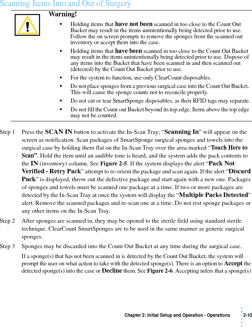
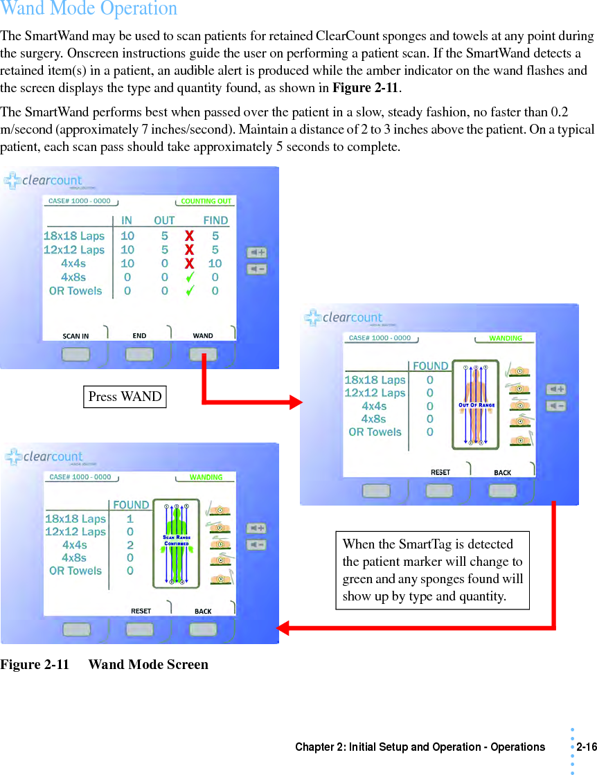
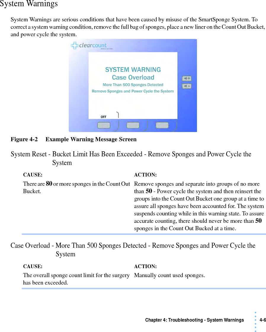
![Chapter 1: System Description - System Components 1-4• • • •••Display and Function Control ButtonsThe display, function control buttons, and volume buttons are the user’s interface to the SmartSponge System. This backlit display shows the following types of screens at various points, depending on the mode of SmartSponge System operation:•Starting, Boot, and Power & Diagnostic screens (during system boot-up)•Standby, Ready to Count or Continuing case, and Count Mode (Scanning In/Counting Out)•Final Report: Counts Equal, or Final Report: Counts Not Equal•Wanding ModeThe Volume Control buttons allow for the adjustment of the SmartSponge System’s internal buzzers. These may be set to four preset levels; off, low, medium, and high. The system will beep when booting up, when it is ready to count, when sponges are scanned in, detected with the SmartWand, or scanned out, and any system alert. Each screen defines the operation of the control buttons for the associated mode of operation. There are three function control buttons along the bottom of the display and two volume control buttons to the right of the display. Figure 1-3 shows the location of the control buttons in relation to the example screen.Figure 1-3 Display and Control ButtonsDisplayFunction Control Button [1]Function Control Button [3]Function Control Button [2]VolumeControlButtonsMode ofOperation](https://usermanual.wiki/ClearCount-Medical-Solutions/CCMS003.Users-Manual/User-Guide-1240151-Page-9.png)
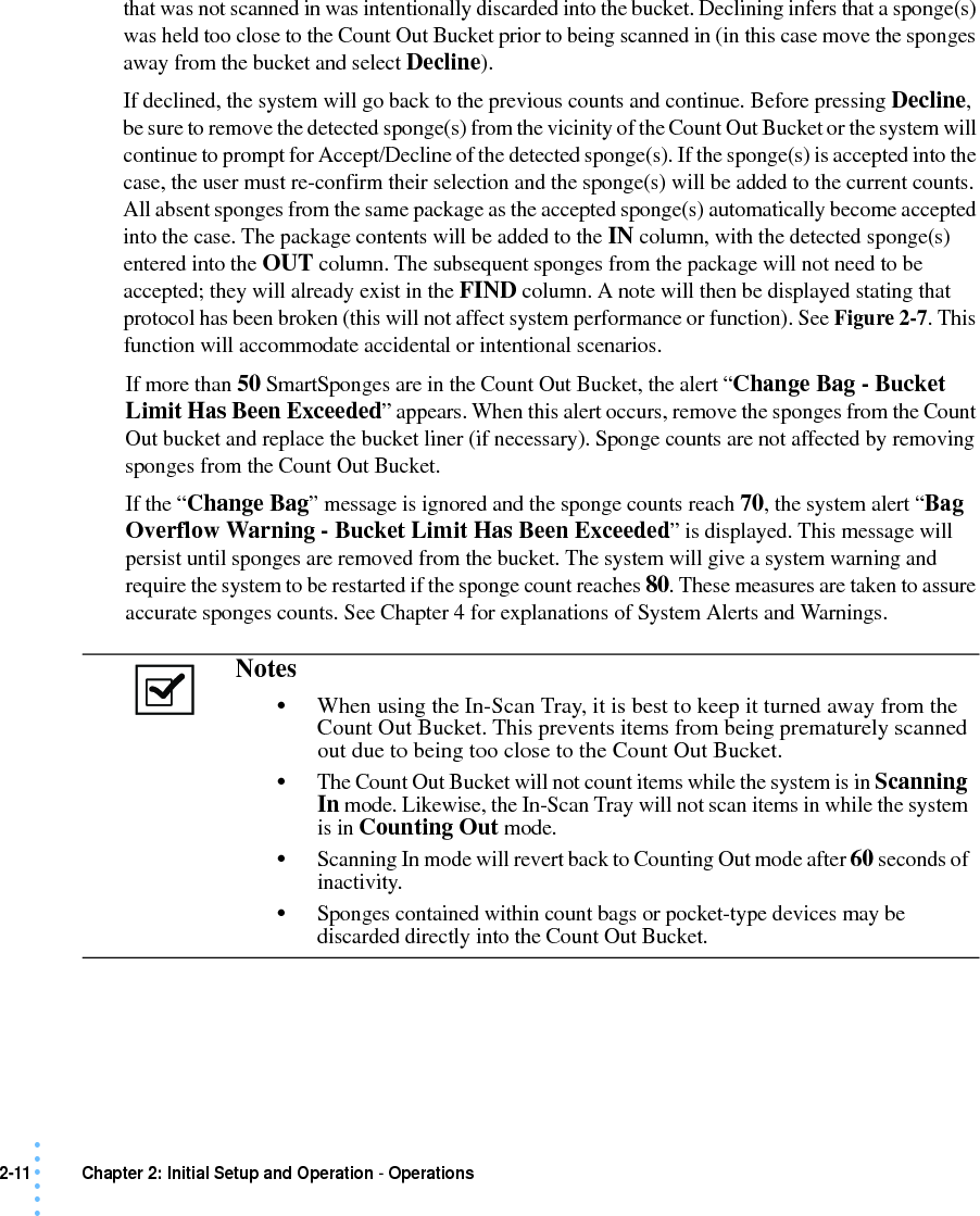
![1-5 Chapter 1: System Description - System Components• • • •••Table 1-3 Display/ControlsDisplay / Controls DescriptionDisplay An LCD that displays information for the user to track sponge counts throughout the surgical procedure. Also displays various modes of operation.Mode of Operation Located in the upper right-hand corner of the Display, this indicates the current status of the system.Volume Control Buttons These up and down buttons control the volume of the audible tones. The Volume of the tones can be set to four different levels; off, low, medium, and high.Function Control Button [1] Allows the following actions; ON - Turns the system on from Standby Mode. SCAN IN - Activates the In-Scan Tray. BACK - Returns to the previous screen and mode. STANDBY - Returns the system to Standby Mode.Function Control Button [2] Allows; END - Exits Count Mode and proceeds to the Final Report screen for verification before ending a case. RESET - Clears the detection status for a rescan in Wanding Mode. Also BACK in Final Report Mode.Function Control Button [3] Allows; WAND - Switches from Counting Out Mode to Wanding Mode. OVERRIDE - Allows the user to end a case without reconciling the sponge counts by using an Override Card. END CASE - Saves case data and returns system to Standby Mode. BACK - Returns to the previous screen and mode.](https://usermanual.wiki/ClearCount-Medical-Solutions/CCMS003.Users-Manual/User-Guide-1240151-Page-10.png)