Comtrend AR-5312U A/VDSL Bonded Router User Manual UM AR5312u A1 0 FCC
Comtrend Corporation A/VDSL Bonded Router UM AR5312u A1 0 FCC
UserManual.wiki
>
Comtrend
>
AR-5312U User Manual
>
5.User manual-2
Contents
1.
5.User manual-1
2.
5.User manual-2
5.User manual-2
Navigation menu
Upload a User Manual
Namespaces
Wiki Guide
HTML
PDF
Info
Views
User Manual
Discussion / Help
Navigation
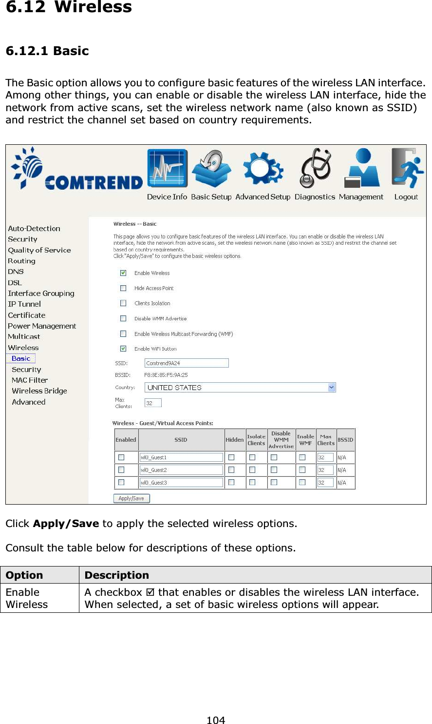
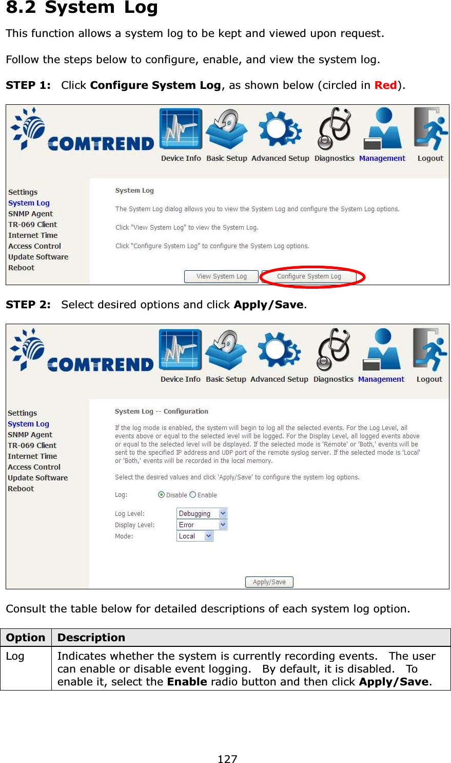
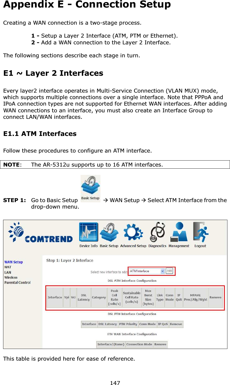
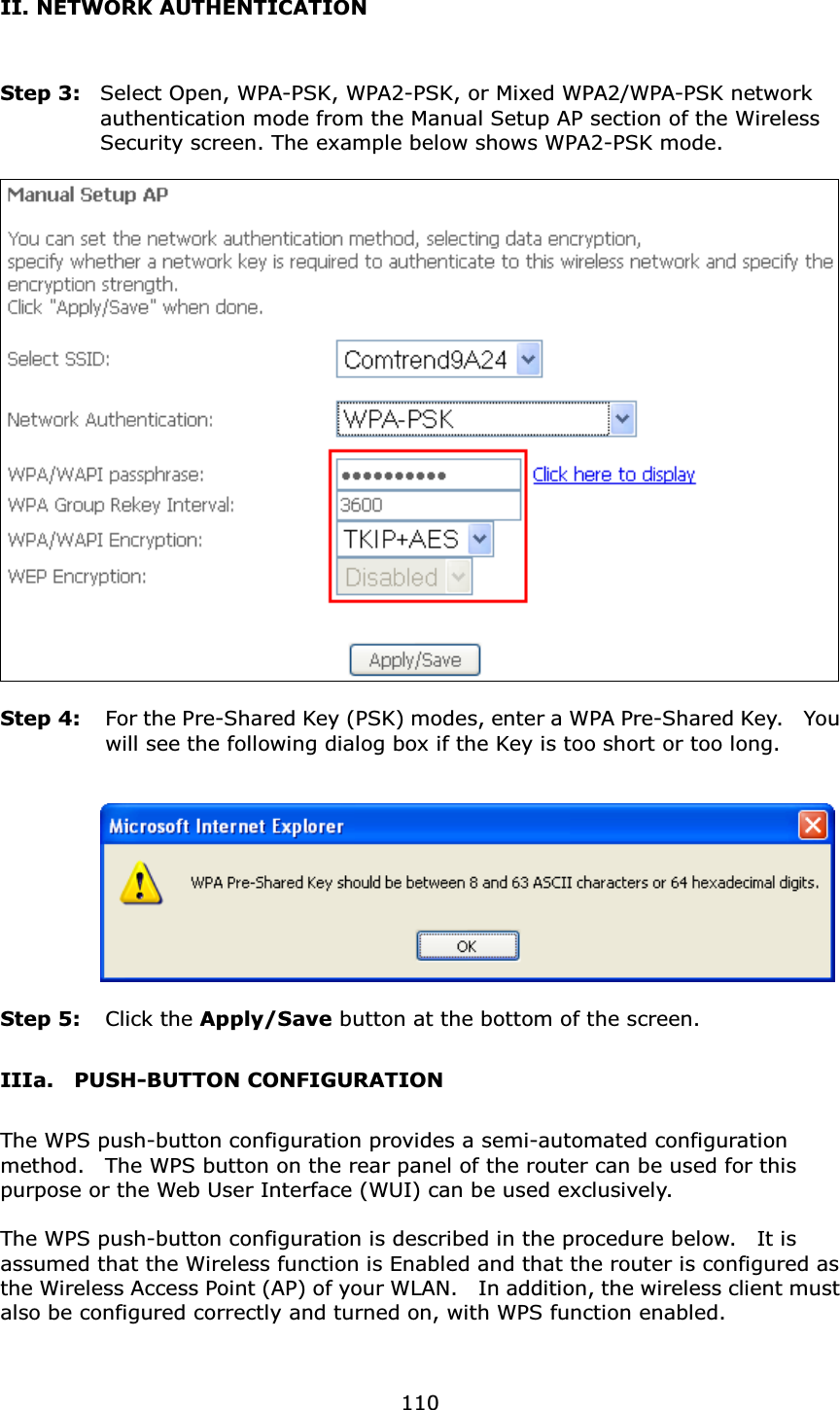
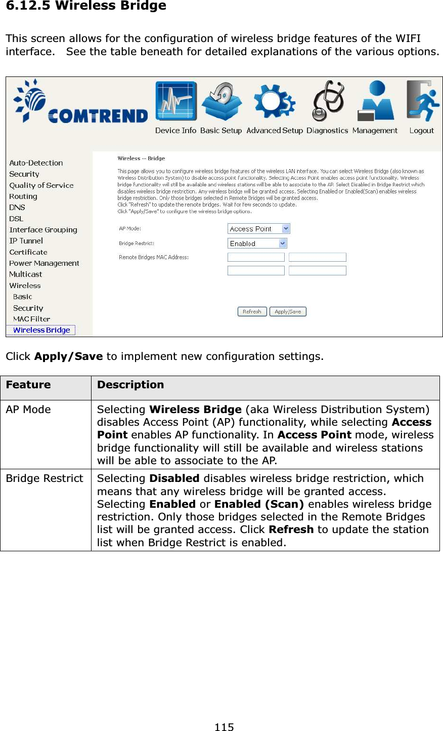
![105Option Description Hide Access Point Select Hide Access Point to protect the access point from detection by wireless active scans. To check AP status in Windows XP, open Network Connections from the start Menu and select View Available Network Connections. If the access point is hidden, it will not be listed there. To connect a client to a hidden access point, the station must add the access point manually to its wireless configuration. Clients Isolation When enabled, it prevents client PCs from seeing one another in My Network Places or Network Neighborhood. Also, prevents one wireless client communicating with another wireless client. Disable WMM Advertise Stops the router from ‘advertising’ its Wireless Multimedia (WMM) functionality, which provides basic quality of service for time-sensitive applications (e.g. VoIP, Video). Enable Wireless Multicast Forwarding Select the checkbox to enable this function. Enable WiFi Button Select the checkbox to enable the WiFi button. SSID [1-32 characters] Sets the wireless network name. SSID stands for Service Set Identifier. All stations must be configured with the correct SSID to access the WLAN. If the SSID does not match, that user will not be granted access. BSSID The BSSID is a 48-bit identity used to identify a particular BSS (Basic Service Set) within an area. In Infrastructure BSS networks, the BSSID is the MAC (Media Access Control) address of the AP (Access Point); and in Independent BSS or ad hoc networks, the BSSID is generated randomly. Country A drop-down menu that permits worldwide and specific national settings. Local regulations limit channel range: US= worldwide, Japan=1-14, Jordan= 10-13, Israel= 1-13 Max Clients The maximum number of clients that can access the router. Wireless - Guest / Virtual Access PointsThis router supports multiple SSIDs called Guest SSIDs or Virtual Access Points. To enable one or more Guest SSIDs select the checkboxes in the Enabled column. To hide a Guest SSID select its checkbox in the Hidden column. Do the same for Isolate Clients and Disable WMM Advertise. For a description of these two functions, see the previous entries for “Clients Isolation” and “Disable WMM Advertise”. Similarly, for Enable WMF, Max Clients and BSSID, consult the matching entries in this table. NOTE: Remote wireless hosts cannot scan Guest SSIDs.](https://usermanual.wiki/Comtrend/AR-5312U.5-User-manual-2/User-Guide-2458921-Page-19.png)
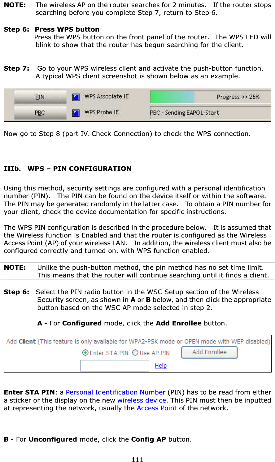
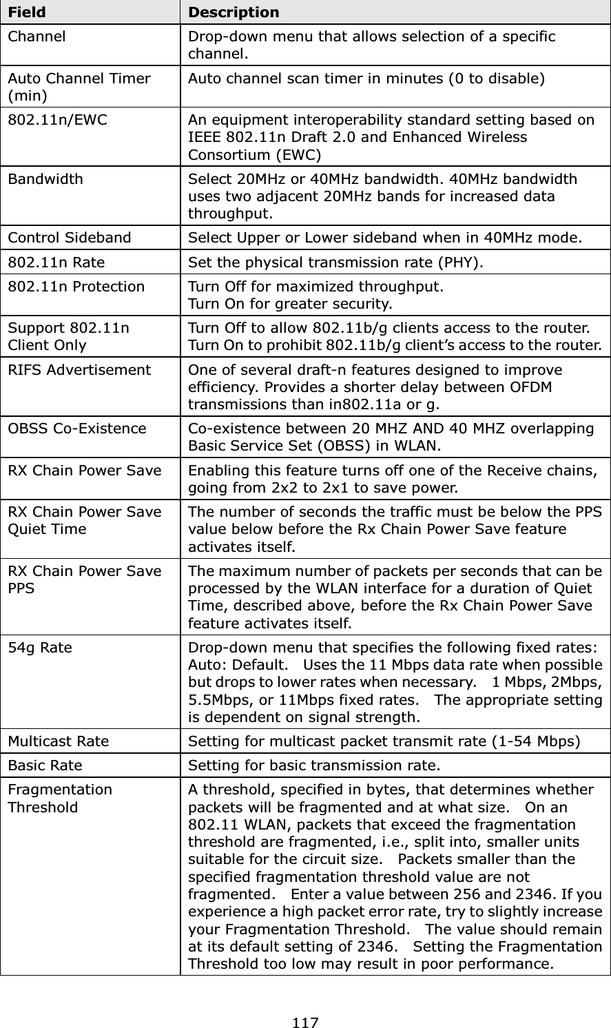
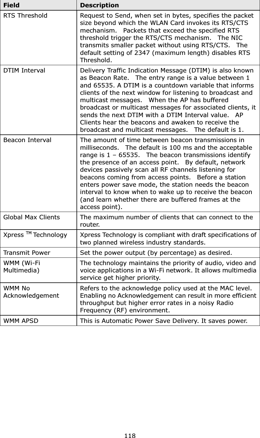
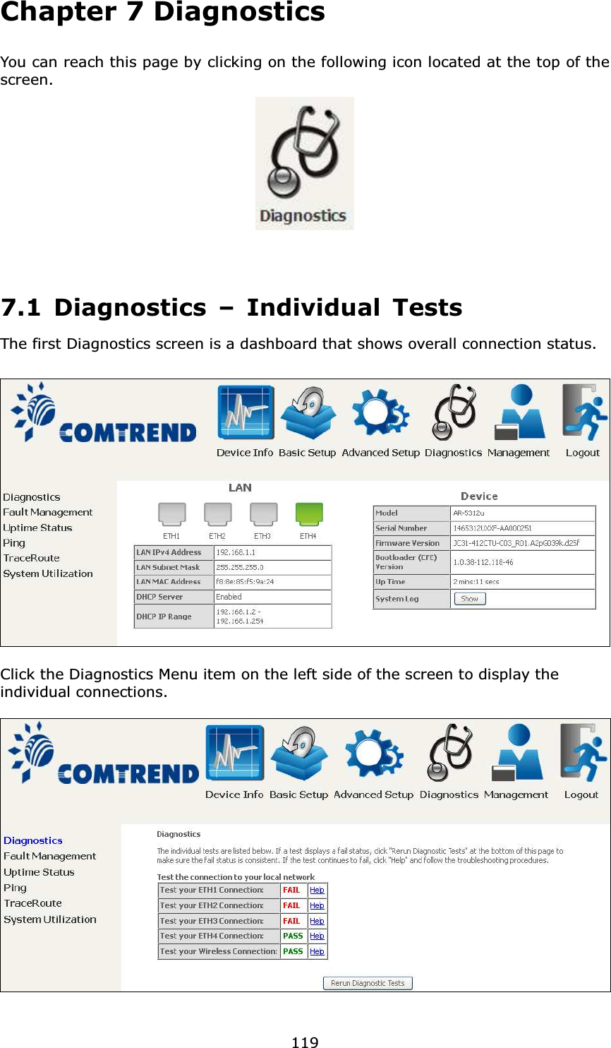
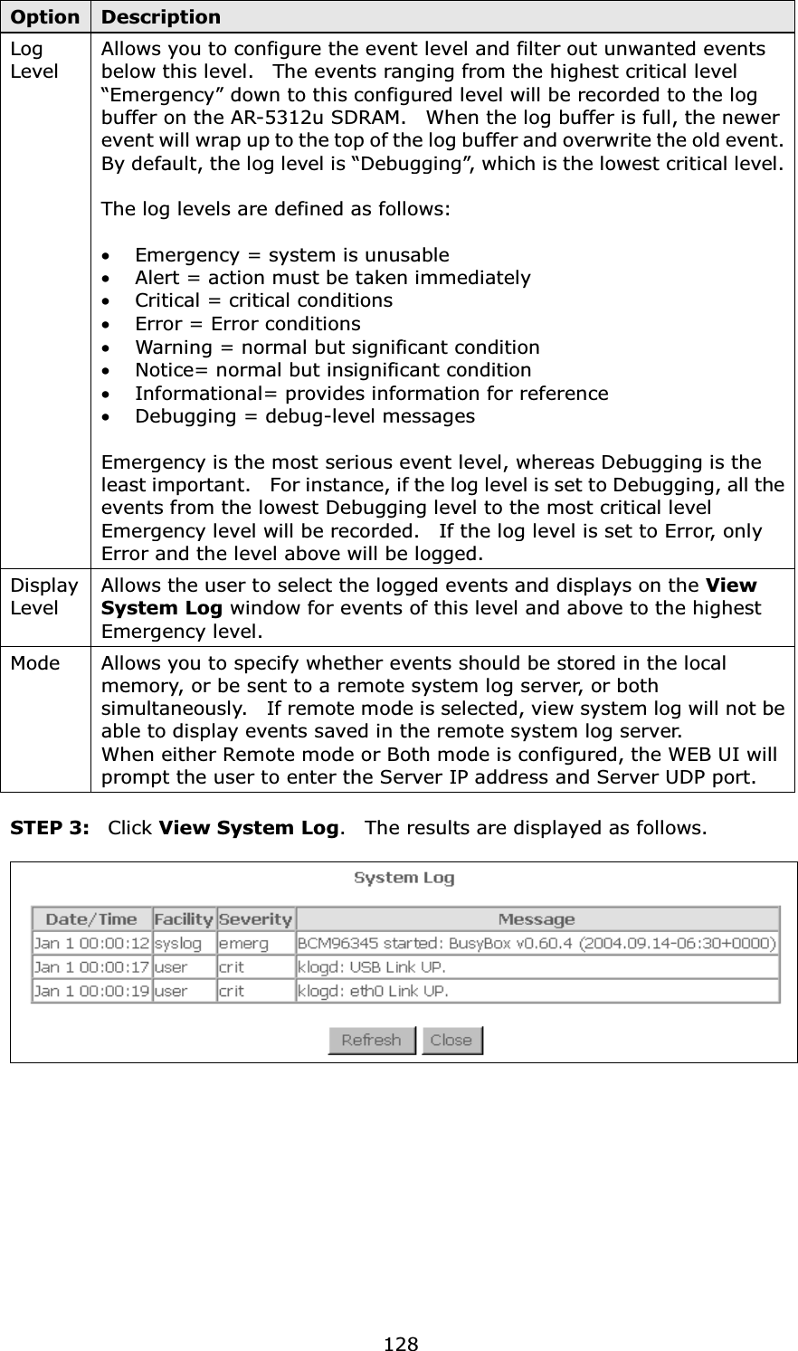
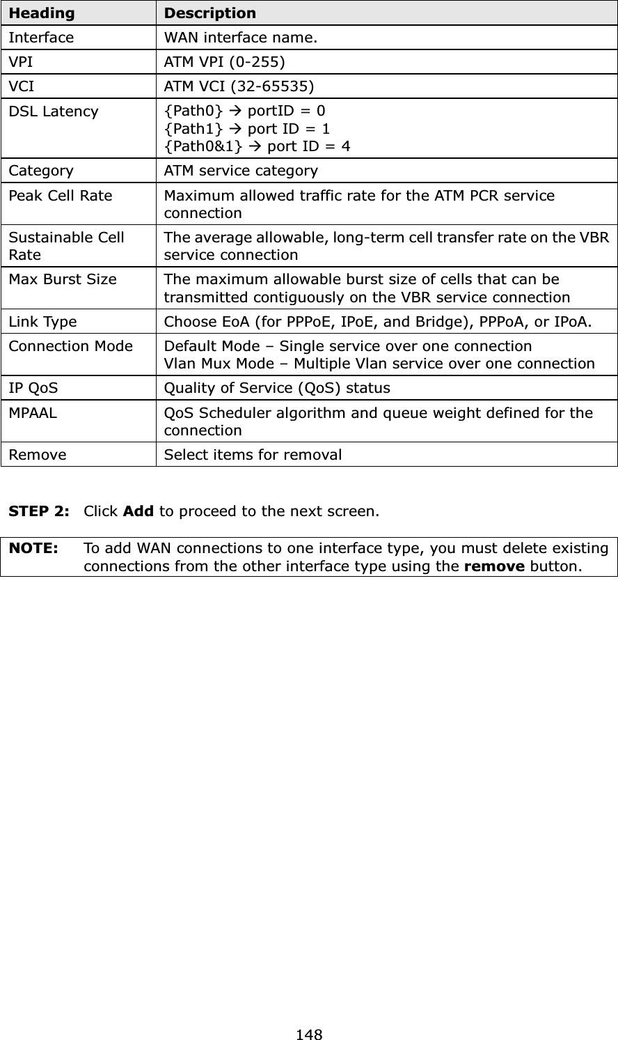
![120 7.2 Fault Management Item Description Maintenance Domain (MD) Level Management space on the network, the larger the domain, the higher the level valueDestination MAC Address Destination MAC address for sending the loopback message802.1Q VLAN ID: [0-4095] 802.1Q VLAN used in VDSL PTM mode Set MD Level Save the Maintenance domain level. Send Loopback Send loopback message to destination MAC address. Send Linktrace Send traceroute message to destination MAC address.](https://usermanual.wiki/Comtrend/AR-5312U.5-User-manual-2/User-Guide-2458921-Page-34.png)