Connect One SM2144N1 Nano WiReach 802.11b/g, 2144 User Manual AT i Programmer s Manual
Connect One Ltd. Nano WiReach 802.11b/g, 2144 AT i Programmer s Manual
UserManual.wiki
>
Connect One
>
SM2144N1 User Manual
Users Manual
Navigation menu
Upload a User Manual
Namespaces
Wiki Guide
HTML
PDF
Info
Views
User Manual
Discussion / Help
Navigation


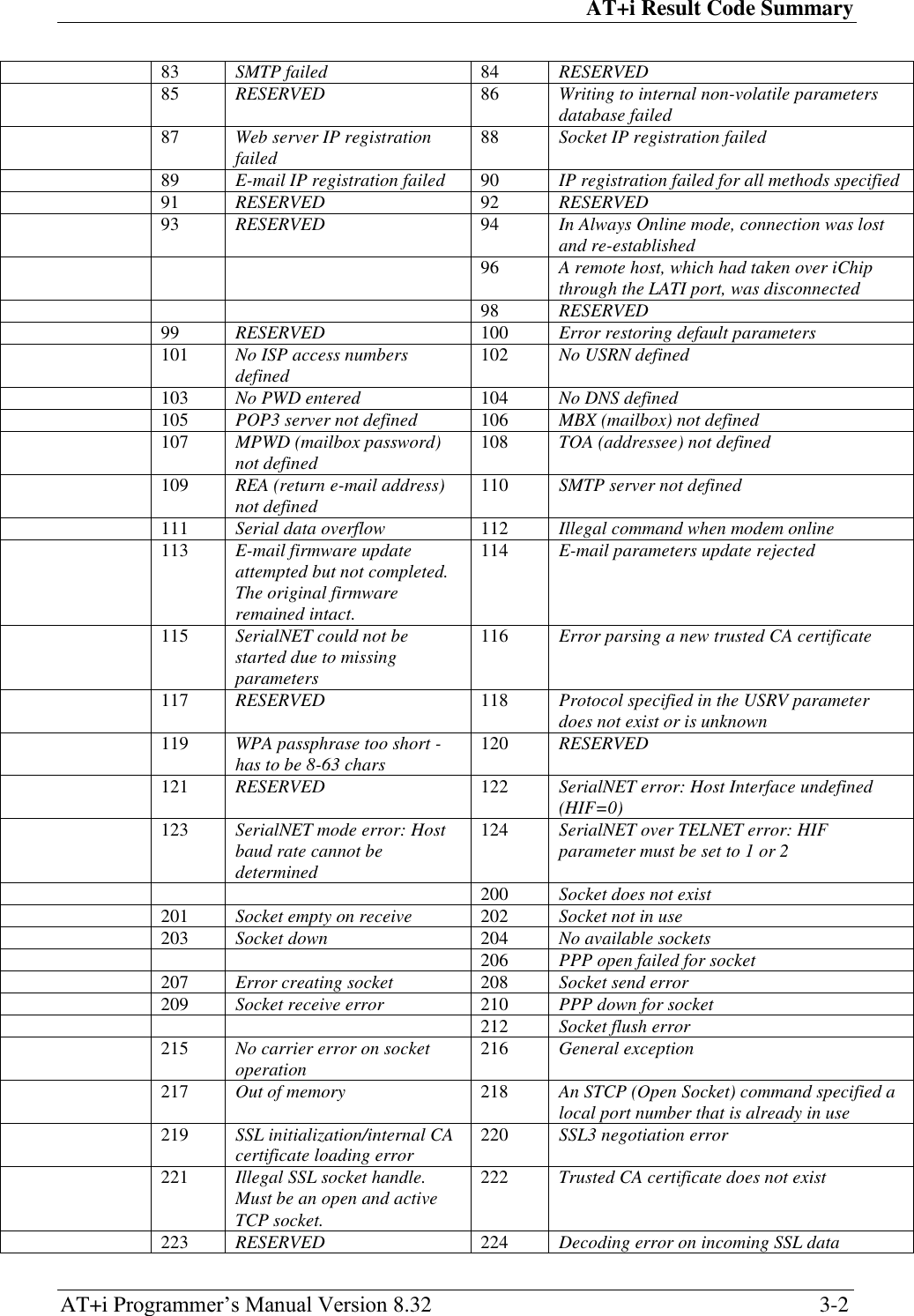
![Contents AT+i Programmer‘s Manual Version 8.32 iv Contents 1 AT+i Command Set ............................................................................................... 1-1 1.1 SCOPE .............................................................................................................. 1-1 1.2 AT+I COMMAND GUIDELINES ......................................................................... 1-1 1.3 AT+I COMMAND FORMAT ............................................................................... 1-1 1.4 ESCAPE CODE SEQUENCE ................................................................................ 1-2 1.5 SOCKET COMMAND ABORT ............................................................................. 1-2 1.6 FLEXIBLE HOST AND MODEM INTERFACES ..................................................... 1-2 1.7 AUTO BAUD RATE DETECTION ........................................................................ 1-3 1.8 HIGH SPEED USART ....................................................................................... 1-4 1.9 RESET VIA SERIAL LINK .................................................................................. 1-4 1.10 ENTERING RESCUE MODE DURING RUNTIME .................................................. 1-5 1.11 INTERNET SESSION HANG-UP PROCEDURE (MODEM ONLY) ........................... 1-5 1.12 MODEM STARTUP ............................................................................................ 1-5 1.13 ANALOG-TO-DIGITAL CONVERTER ................................................................. 1-5 1.14 ICHIP READINESS INDICATION ......................................................................... 1-6 1.15 PROGRAMMING ICHIP‘S SERIAL NUMBER INTO FLASH MEMORY .................... 1-6 1.15.1 +iSNUM — iChip Serial Number ........................................................... 1-6 1.16 PROGRAMMING A UNIQUE ID STRING INTO FLASH MEMORY .......................... 1-7 1.16.1 +iUID — Unique ID ............................................................................... 1-7 2 General Format ..................................................................................................... 2-1 2.1 AT+I COMMANDS BY CATEGORY .................................................................... 2-1 3 AT+i Result Code Summary ................................................................................ 3-1 4 Report Status ......................................................................................................... 4-1 4.1 +I[!]RPI — REPORT STATUS ............................................................................ 4-1 4.2 STATUS MESSAGE FORMAT ............................................................................. 4-3 5 Connection ............................................................................................................. 5-1 5.1 +IBDRA — FORCES ICHIP INTO AUTO BAUD RATE MODE ............................. 5-1 5.2 +IUP — INITIATE INTERNET SESSION .............................................................. 5-2 5.3 +ITUP — TRIGGERED INTERNET SESSION INITIATION .................................... 5-3 5.4 +IDOWN — TERMINATE INTERNET SESSION ................................................. 5-5 5.5 +IPING — SEND A PING REQUEST TO A REMOTE SERVER ............................ 5-6 6 E-mail Send Commands ....................................................................................... 6-1 6.1 +IEMA — ACCEPT ASCII-CODED LINES FOR E-MAIL SEND ......................... 6-1 6.2 +IEMB — ACCEPT BINARY DATA FOR IMMEDIATE E-MAIL SEND ................. 6-2 6.3 +IE* — TERMINATE BINARY E-MAIL ............................................................. 6-4 7 E-Mail Retrieve ...................................................................................................... 7-1 7.1 +IRML — RETRIEVE MAIL LIST ..................................................................... 7-1 7.2 +IRMH — RETRIEVE MAIL HEADER .............................................................. 7-2 7.3 +IRMM — RETRIEVE MAIL MESSAGE ............................................................ 7-3](https://usermanual.wiki/Connect-One/SM2144N1/User-Guide-1162098-Page-4.png)
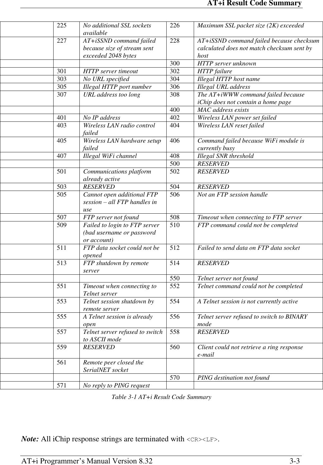
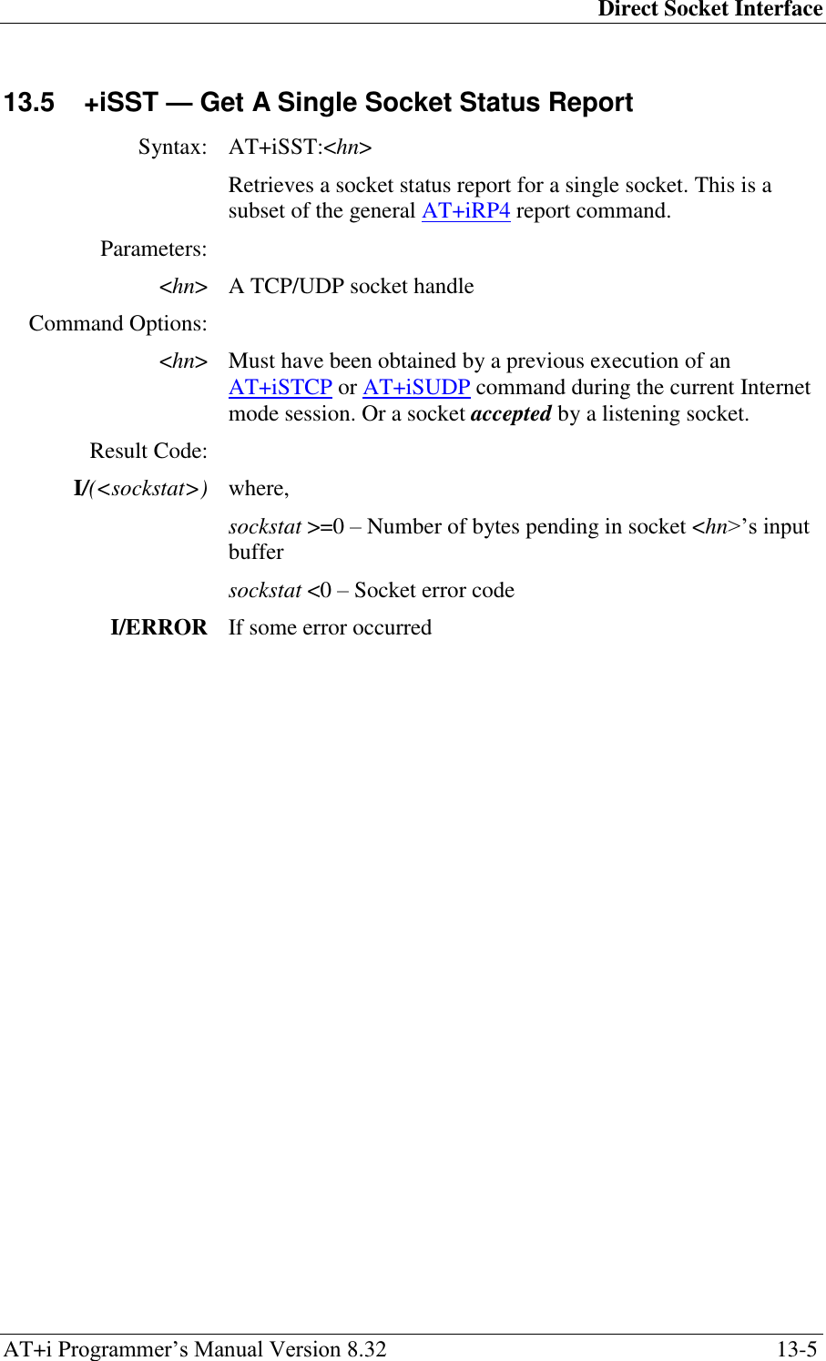
![Contents AT+i Programmer‘s Manual Version 8.32 v 8 HTTP Client Interface .......................................................................................... 8-1 8.1 +IRLNK — RETRIEVE LINK ............................................................................ 8-1 8.2 +ISLNK — SUBMIT A POST REQUEST TO A WEB SERVER ............................ 8-3 9 SerialNET Mode Initiation ................................................................................... 9-1 9.1 +ISNMD — ACTIVATE SERIALNET MODE .................................................... 9-1 10 Web Server Interface .......................................................................................... 10-1 10.1 +IWWW — ACTIVATE EMBEDDED WEB SERVER ........................................ 10-1 10.2 +IWNXT — RETRIEVE NEXT CHANGED WEB PARAMETER .......................... 10-2 11 File Transfer Protocol (FTP) .............................................................................. 11-1 11.1 +I[@]FOPN — FTP OPEN SESSION .............................................................. 11-1 11.2 +IFDL — FTP DIRECTORY LISTING .............................................................. 11-2 11.3 +IFDNL — FTP DIRECTORY NAMES LISTING .............................................. 11-3 11.4 +IFMKD — FTP MAKE DIRECTORY ............................................................ 11-4 11.5 +IFCWD — FTP CHANGE WORKING DIRECTORY ........................................ 11-5 11.6 +IFSZ — FTP FILE SIZE ............................................................................... 11-6 11.7 +IFRCV — FTP RECEIVE FILE ..................................................................... 11-7 11.8 +IFSTO — FTP OPEN FILE FOR STORAGE .................................................... 11-8 11.9 +IFAPN — FTP OPEN FILE FOR APPENDING ................................................ 11-9 11.10 +IFSND — FTP SEND FILE DATA .............................................................. 11-10 11.11 +IFCLF — FTP CLOSE FILE ....................................................................... 11-11 11.12 +IFDEL — FTP DELETE FILE ..................................................................... 11-12 11.13 +IFCLS — FTP CLOSE SESSION ................................................................. 11-13 12 Telnet Client ......................................................................................................... 12-1 12.1 +ITOPN — TELNET OPEN SESSION .............................................................. 12-1 12.2 +ITRCV — TELNET RECEIVE DATA ............................................................. 12-2 12.3 +ITSND — TELNET SEND DATA LINE .......................................................... 12-3 12.4 +ITBSN[%] — TELNET SEND A BYTE STREAM............................................ 12-4 12.5 +ITFSH[%] — FLUSH TELNET SOCKET‘S OUTBOUND DATA ........................ 12-5 12.6 +ITCLS — TELNET CLOSE SESSION ............................................................. 12-6 13 Direct Socket Interface ....................................................................................... 13-1 13.1 +ISTCP — OPEN AND CONNECT A TCP SOCKET ......................................... 13-1 13.2 +ISUDP — OPEN A CONNECTIONLESS UDP SOCKET ................................... 13-2 13.3 +ILTCP — OPEN A TCP LISTENING SOCKET ............................................... 13-3 13.4 +ILSST — GET A LISTENING SOCKET‘S ACTIVE CONNECTION STATUS ....... 13-4 13.5 +ISST — GET A SINGLE SOCKET STATUS REPORT ....................................... 13-5 13.6 +ISCS — GET A SOCKET CONNECTION STATUS REPORT ............................. 13-6 13.7 +ISSND[%] — SEND A BYTE STREAM TO A SOCKET................................... 13-7 13.8 +ISRCV — RECEIVE A BYTE STREAM FROM A SOCKET‘S INPUT BUFFER .... 13-9 13.9 +IGPNM — GET PEER NAME FOR A SPECIFIED SOCKET ............................ 13-11 13.10 +ISDMP — DUMP SOCKET BUFFER ............................................................ 13-12 13.11 +ISFSH[%] — FLUSH SOCKET‘S OUTBOUND DATA ................................... 13-13 13.12 +ISCLS — CLOSE SOCKET ......................................................................... 13-14](https://usermanual.wiki/Connect-One/SM2144N1/User-Guide-1162098-Page-5.png)
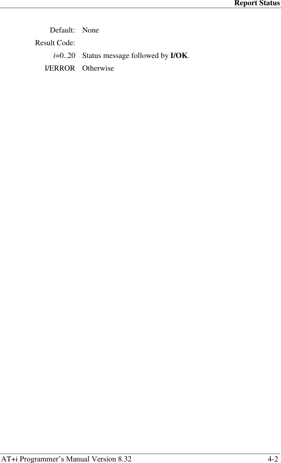
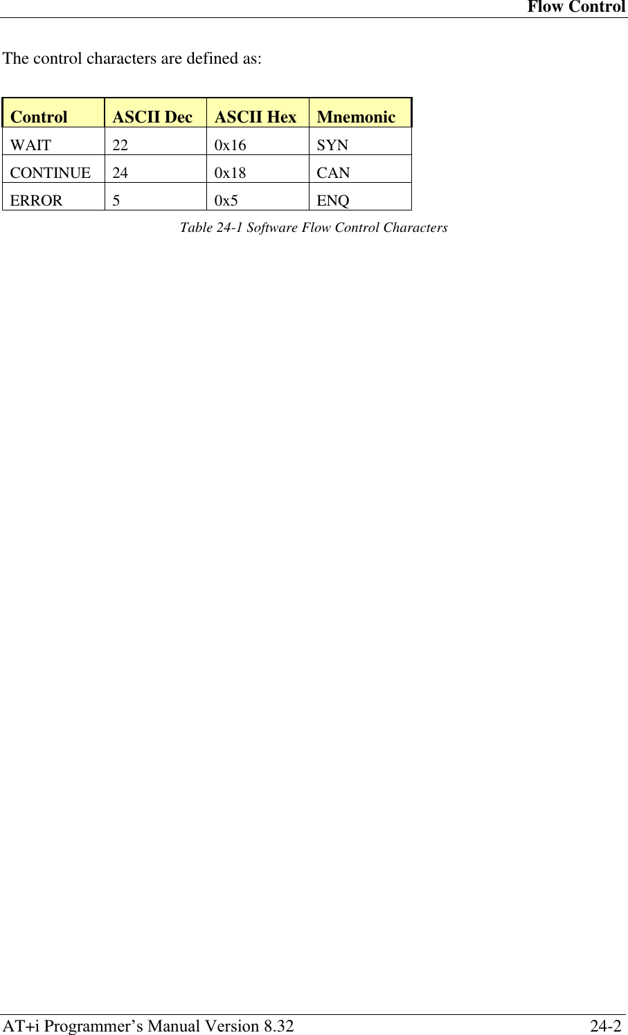
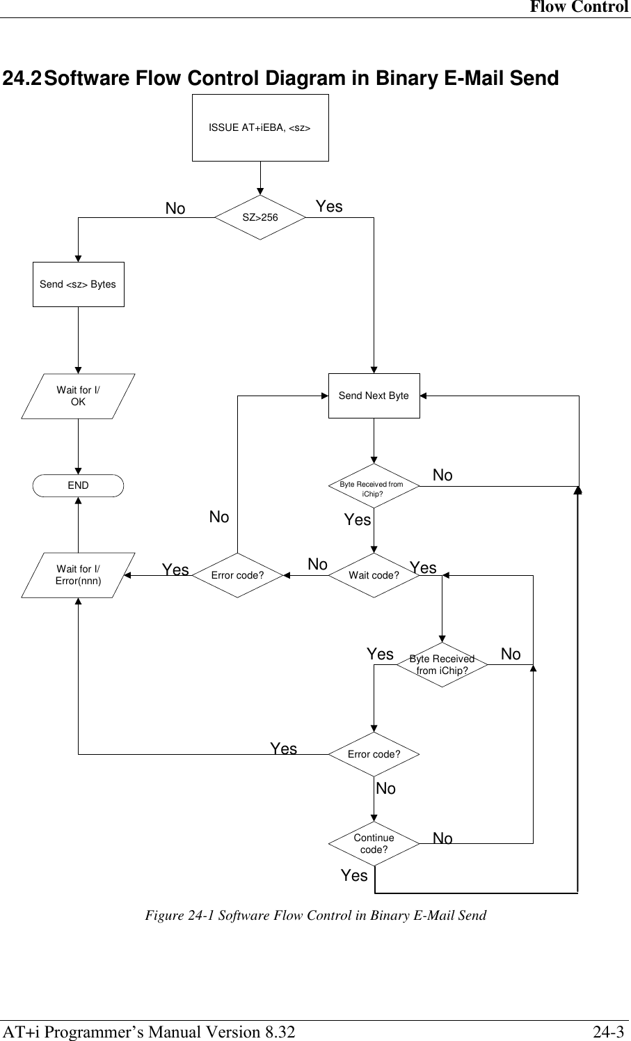
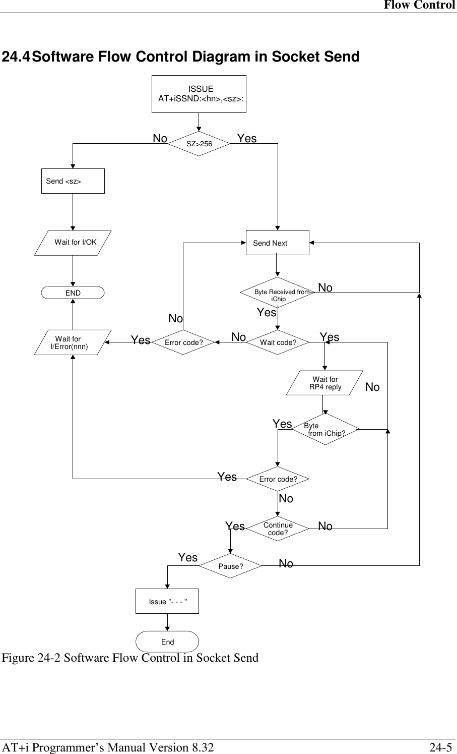
![Contents AT+i Programmer‘s Manual Version 8.32 vii 21 Secure Socket Protocol ........................................................................................ 21-1 21.1 ESTABLISHING AN SSL3/TLS1 SOCKET CONNECTION ................................. 21-1 21.2 SENDING AND RECEIVING DATA OVER AN SSL3/TLS1 SOCKET ................... 21-1 21.3 SSL3/TLS1 HANDSHAKE AND SESSION EXAMPLE ........................................ 21-1 21.4 SECURE FTP SESSION ON ICHIP ..................................................................... 21-2 21.5 +ISSL — SECURE SOCKET CONNECTION HANDSHAKE ................................. 21-4 21.6 +I[@]FOPS — SECURE FTP OPEN SESSION ................................................. 21-5 22 Network Time Client ........................................................................................... 22-1 23 MIME Encapsulated E-Mail Messages ............................................................. 23-1 23.1 ICHIP-GENERATED BINARY MESSAGE FORMATS .......................................... 23-1 23.2 MIME-RELATED AT+I COMMANDS AND PARAMETERS ................................ 23-1 23.2.1 Binary Attachment Parameters ............................................................. 23-2 23.2.2 Defining A Textual Body for Binary Messages ..................................... 23-2 23.3 MIME-ENCAPSULATED E-MAIL MESSAGE FORMAT .................................... 23-3 24 Flow Control ........................................................................................................ 24-1 24.1 HOST ICHIP SOFTWARE FLOW CONTROL .................................................. 24-1 24.2 SOFTWARE FLOW CONTROL DIAGRAM IN BINARY E-MAIL SEND ................. 24-3 24.3 SOFTWARE FLOW CONTROL DURING A SOCKET SEND.................................. 24-4 24.4 SOFTWARE FLOW CONTROL DIAGRAM IN SOCKET SEND .............................. 24-5 24.5 HOST ICHIP HARDWARE FLOW CONTROL ................................................ 24-6 25 Remote Firmware Update .................................................................................. 25-1 25.1 INTRODUCTION .............................................................................................. 25-1 25.2 UPDATING FIRMWARE FROM A REMOTE SERVER .......................................... 25-1 25.3 +IRFU — REMOTE FIRMWARE UPDATE ........................................................ 25-3 26 iChip Parameter Update ..................................................................................... 26-1 26.1 INTRODUCTION .............................................................................................. 26-1 26.2 REMOTE PARAMETER FILE (RPF) STRUCTURE .............................................. 26-1 26.3 HEADER PARAMETER NAMES AND VALUES .................................................. 26-2 26.4 UPLOADING A PARAMETERS UPDATE FILE TO ICHIP ..................................... 26-3 27 iChip Embedded Web Server ............................................................................. 27-1 27.1 INTRODUCTION .............................................................................................. 27-1 27.2 FEATURES ...................................................................................................... 27-1 27.3 WEB SERVER MODES .................................................................................... 27-2 27.4 THE APPLICATION WEBSITE .......................................................................... 27-2 27.5 PARAMETER TAGS ......................................................................................... 27-3 27.6 ICHIP CONFIGURATION MODE ....................................................................... 27-3 27.7 HOST INTERACTION MODE ............................................................................ 27-4 27.8 WEBSITE CREATION, PACKING, AND UPLOADING ......................................... 27-5 27.9 MANIPULATING VARIABLES IN THE APPLICATION WEBSITE ......................... 27-5 27.10 SECURITY AND RESTRICTIONS ....................................................................... 27-7 27.11 PARAMETER UPDATE ERROR HANDLING ....................................................... 27-8](https://usermanual.wiki/Connect-One/SM2144N1/User-Guide-1162098-Page-7.png)
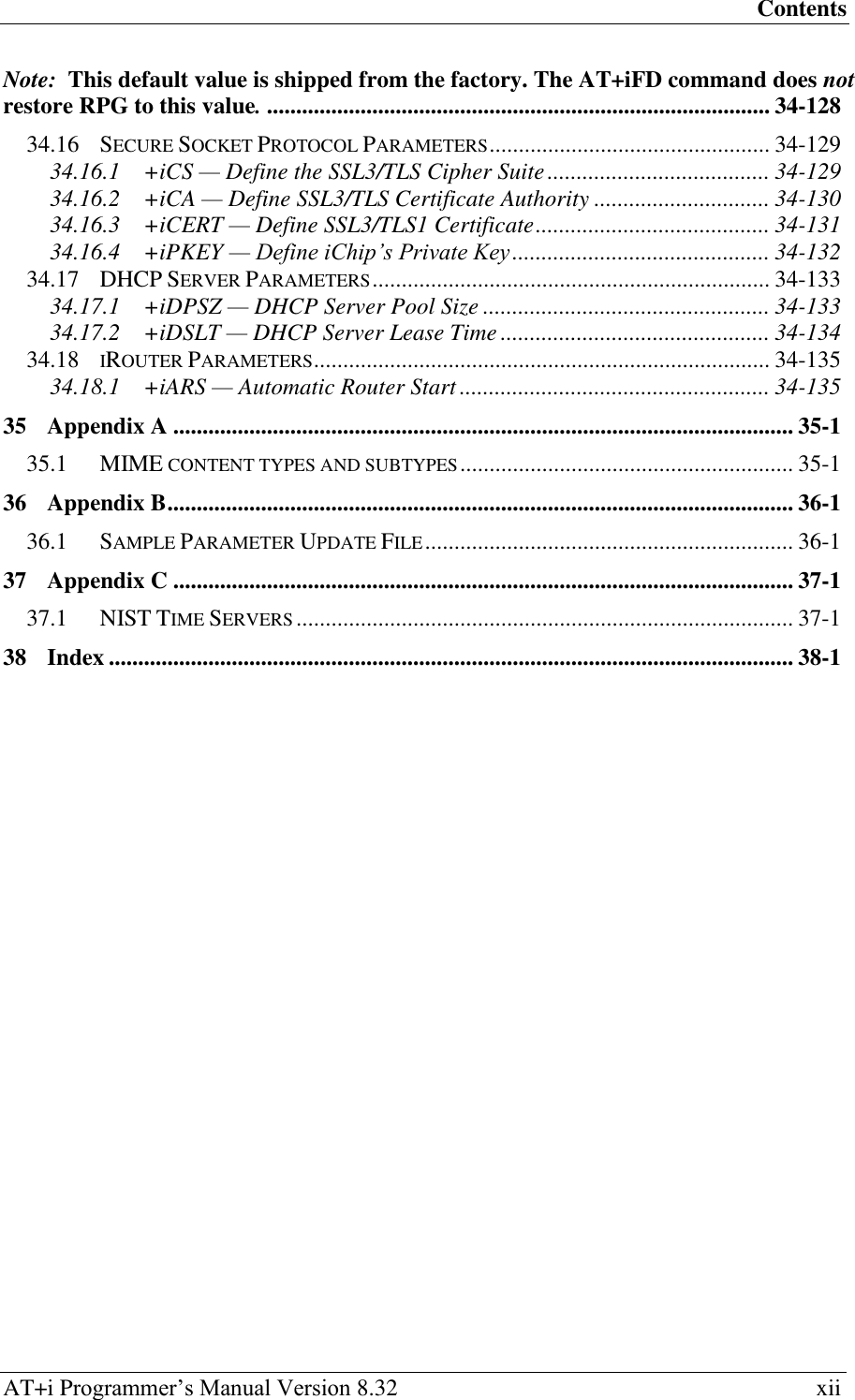
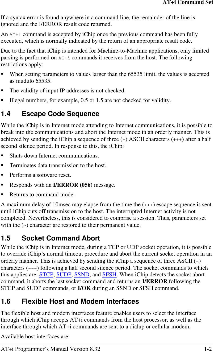
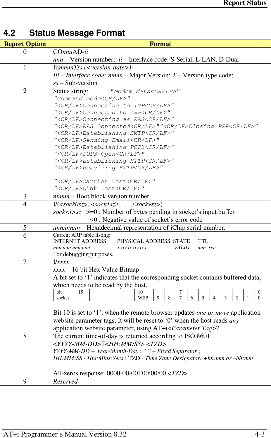
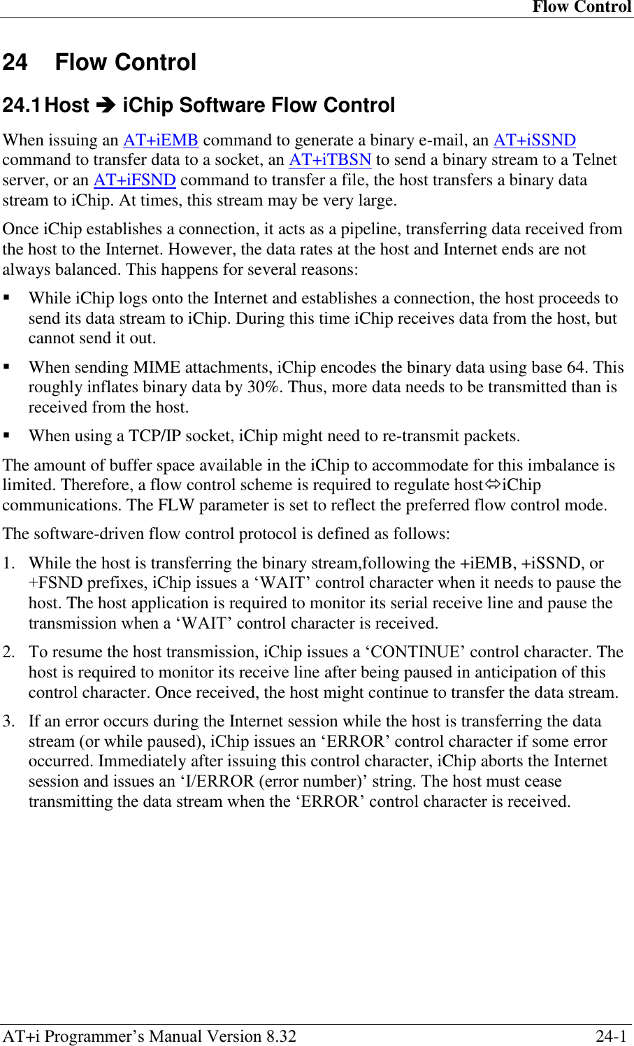
![General Format AT+i Programmer‘s Manual Version 8.32 2-1 2 General Format AT+i<cc>[<del>[<parameter> | #UFn]…]<CR> <cc> (or <par>) 2–4 letter command code (<cc>) or parameter name (<par>) <del> Delimiter: '=', '~', '?', ':', ‗,‘ <parameter> Optional parameter or data. If <parameter> includes a <del>, as defined above, it must be enclosed in single (‗) or double (―) quotes. The terminating <CR> is considered as a terminating quote as well. #UFn User-field macro substitution <CR> Carriage Return line terminator (ASCII 13) 2.1 AT+i Commands by Category Command Function Parameters/Description AT+i Command prefix Required to precede all commands Host Interface En Echo Mode n=0 Do not echo host characters n=1 Echo all host characters (default upon power-up) This command is equivalent to and interchangeable with ATEn. Parameter Database Maintenance <par>=value -or- <par>:value Set parameter value stored in parameter <par> in nonvolatile memory. <par> retains set value indefinitely after power down. <par>~value Assign single session parameter value value is assigned to parameter <par> for the duration of a single Internet session. Following the session, the original value is restored. <par>? Read parameter Parameter value is returned. <par>=? Parameter allowed values Returns the allowed values for this parameter. FD Factory Defaults Restores all parameters to factory defaults. Status Report RP<i> Request status report Returns a status report value based on <i>. Connection BDRA Auto baud rate mode Forces iChip into auto baud rate detection mode. UP Connect to Internet Forces iChip to go online, establish an Internet session, and optionally register its IP address. TUP Triggered Internet session mode Enters a mode in which iChip goes online in response to triggers from external signals. It also supports a special Always Online mode. DOWN Perform a software reset Performs a software reset. Forces iChip to terminate an Internet session and go offline. PING PING a remote system Sends a PING message and waits for its echo response.](https://usermanual.wiki/Connect-One/SM2144N1/User-Guide-1162098-Page-22.png)
![General Format AT+i Programmer‘s Manual Version 8.32 2-2 Command Function Parameters/Description Send E-mail [!]EMA:<text> Send textual e-mail Defines the textual contents of the e-mail body. Following this command, several text lines can be sent in sequence. [!]EMB:<sz>,<data> Send binary e-mail Prefixes a binary data stream. The data is encapsulated as a base 64 encoded MIME attachment. Following this prefix, exactly <sz> bytes are streamed to iChip. [!]E* Terminate binary e-mail Terminates a binary (MIME attachment) e-mail. Retrieve E-mail [!]RML Retrieve mail list Retrieves an indexed, short form list of all qualifying messages in mailbox. [!]RMH[:<i>] Retrieve header Retrieves only the e-mail header part from the <i>‘th e-mail in the mailbox, or the entire mailbox. [!]RMM[:<i>] Retrieve e-mail Retrieves all e-mail contents of the <i>‘th e-mail in the mailbox, or the entire mailbox. HTTP Client [!]RLNK[:<URL>] Retrieve link Retrieves a file from a URL on a web server. If <URL> is not specified, uses the URL stored in the URL parameter. [!]SLNK:<text> Send POST request Sends a file consisting lines of ASCII to a web server defined in the URL parameter. HTTP Server WWW Activate the web server Activates iChip‘s internal web server. Once activated, remote browsers can surf iChip‘s website. WNXT Retrieve next changed web parameter Returns the parameter tag name and new value of the next web parameter that has been changed as a result of a submit by a remote browser. SerialNET [!|@]SNMD Activate SerialNET mode Activates iChip‘s dedicated serial-to-network SerialNET mode. Telnet Client TOPN Telnet open session Opens a Telnet session to a remote Telnet server. If iChip is not online, it is connected. TRCV Telnet receive Receives data from a remote Telnet server. TSND Telnet send line Sends an ASCII data line to a remote Telnet server. TBSN[%] Telnet send binary stream Sends a binary data stream to a remote Telnet server. TFSH[%] Telnet flush Flushes a Telnet socket‘s outbound data. TCLS Telnet close Closes a Telnet session.](https://usermanual.wiki/Connect-One/SM2144N1/User-Guide-1162098-Page-23.png)
![General Format AT+i Programmer‘s Manual Version 8.32 2-4 Command Function Parameters/Description Socket Interface STCP:<host>, <port>[,<lport>] Socket TCP Opens and connects a TCP socket. If iChip is not online, it is connected. The responding system is assumed to be a server listening on the specified socket. Returns a handle to the socket. SUDP: <host>,<rport> [,<lport>] Socket UDP Opens, connects, and optionally binds a UDP socket. If iChip is not online, it is connected. Returns a handle to the socket. LTCP: <port>,<backlog> Listening socket Opens a TCP listening socket on <port>. Allows a maximum of <backlog> concurrent connections. Returns a handle to the socket. Up to two listening sockets are supported. LSST:<hn> Listening socket status Returns a list of active socket handles accepted for a listening socket identified by handle <hn>. SST:<hn> Single socket status Returns status of a single socket identified by handle <hn>. A subset of RP4 report. SCS:<hn> Socket connection status Returns status of a single socket identified by handle <hn>. A subset of RP4 report. Does not report number of buffered characters. SSND[%]: <hn>,<sz>:<stream> Socket send Sends a byte stream of size <sz> to the socket identified by handle <hn>. The % flag indicates automatic socket flush. SRCV:<hn> [,<max>] Socket receive Receives a byte stream from the socket identified by handle <hn>. Accepts up to <max> bytes. If <max> is not specified, all available bytes are retrieved. GPNM:<hn> Get peer name Retrieves peer name (<IP>:<port>) of a remote connection to the TCP/UDP socket specified by socket handle <hn>. SDMP:<hn> Dump socket buffer Dumps all buffered data currently accumulated in a socket‘s input buffer. The socket remains open. SFSH[%]:<hn> Flush socket‘s outbound data Flushes (sends immediately) data accumulated in a socket‘s outbound buffer. If the flush-and-acknowledge flag (!) is specified, iChip waits for peer to acknowledge receipt of the TCP packet. [!]SCLS:<hn> Close socket Closes a TCP/UDP socket. If that socket is the only socket open and the stay online flag (!) is not specified, iChip terminates the Internet session and goes offline. SSL:<hn> SSL3/TLS1 socket connection Negotiates an SSL3/TLS1 connection over an active TCP socket.](https://usermanual.wiki/Connect-One/SM2144N1/User-Guide-1162098-Page-25.png)

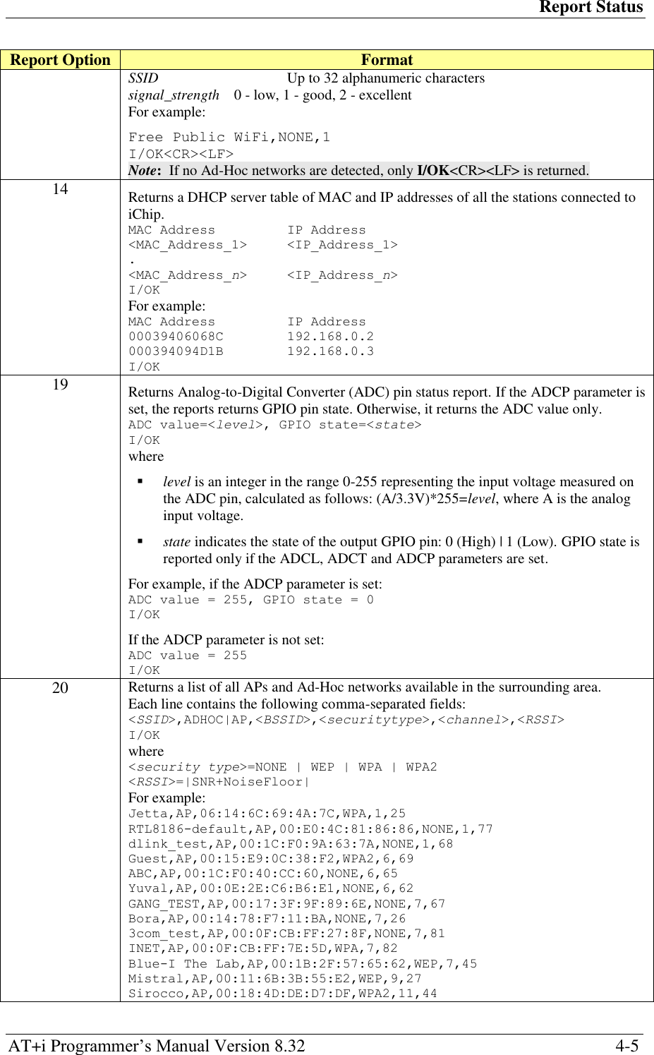
![Report Status AT+i Programmer‘s Manual Version 8.32 4-1 4 Report Status 4.1 +i[!]RPi — Report Status Syntax: AT+i[!]RPi Returns a status report. Parameters: i=0..20 Command Options: i=0 Returns the iChip part number. i=1 Returns the current firmware revision and date. i=2 Returns the connection status. i=3 Returns boot-block revision and date. i=4 Returns iChip socket status. i=5 Returns a unique serial number. i=6 Returns current ARP table. i=7 Returns socket buffers utilization bitmap. iChip‘s DATA_RDY signal can be used to signal socket buffer status changes in hardware. This signal is raised when new data in one or more sockets is available, or when a remote browser has changed a web parameter. It is lowered when any socket or web parameter is read. i=8 Returns current time-of-day based on time retrieved from the Network Time Server and the GMT offset setting. Returns an all-zero response if a timestamp has not yet been retrieved from the network since the last power-up. i=9 Reserved i=10 and AT+i!RP10 Return two different status reports about the current Wireless LAN connection. i=11 Returns a list of all Access Points available in the surrounding area. AT+i!RP11 Returns a list of all Ad-Hoc networks available in the surrounding area. i=14 Returns a DHCP server table of MAC and IP addresses of all the stations connected to iChip. i=19 Returns Analog-to-Digital Converter (ADC) pin status report. i=20 Returns a list of all APs and Ad-Hoc networks available in the surrounding area.](https://usermanual.wiki/Connect-One/SM2144N1/User-Guide-1162098-Page-31.png)
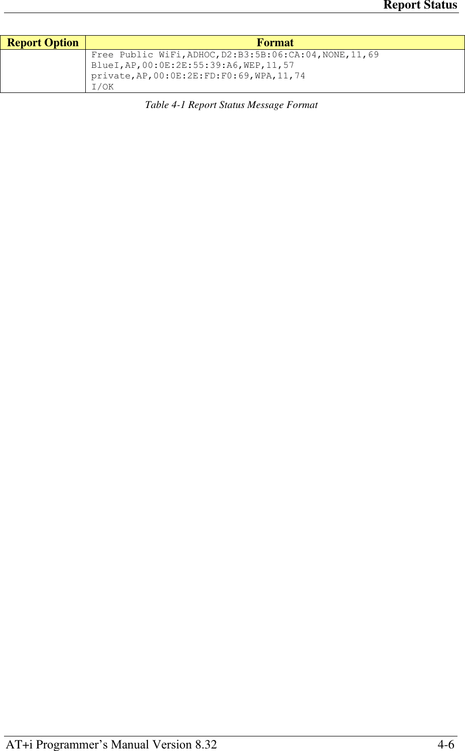
![Report Status AT+i Programmer‘s Manual Version 8.32 4-4 Report Option Format 10 I/(<port stat>, <xfer rate>, <sig level>, <lnk qual>) port stat -Port Status: 0: Wireless LAN adapter not present 1: Wireless LAN adapter disabled 2: Searching for initial connection 4: Connected 5: Out of range xfer rate -- Transfer rate in the range 1..54 sig level -- Signal level [%], in the range 0..100 lnk qual -- Link quality [%], in the range 0..100 I/OK AT+i!RP10 Returns a report of the current WLAN connection. <SSID>,<BSSID>,<security type>,<WPA status>,<channel>,<SNR> I/OK where <security type>=NONE|WEP64|WEP128|WPA|WPA2 <WPA status>=Completed|Not Completed <WPA status> indicates, when WPA/WPA2 security is specified, whether WPA negotiation completed or not. Notes: For Ad-Hoc networks, SSID starts with (!). WPA status is reported whether WPA negotiation completed or not. For example: Jetta,06:14:6C:69:4A:7C,WPA,Completed,1,68 I/OK 11 iChip scans all available Access Points (APs) in the surrounding area and returns a list of APs. Each line contains the following comma-separated fields: SSID, security scheme, and signal strength. The AP having the strongest signal appears first. <SSID>,<security_scheme>,<signal_strength><CR><LF> <SSID>,<security_scheme>,<signal_strength><CR><LF> . . <SSID>,<security_scheme>,<signal_strength><CR><LF> I/OK<CR><LF> where, SSID – Up to 32 alphanumeric characters security_scheme – None | WEP | WPA signal_strength 0 - low, 1 - good, 2 - excellent Note: If no APs are detected, only I/OK<CR><LF> is returned. AT+i!RP11 Returns a list of all Ad-Hoc networks available in the surrounding area. Each line contains the following comma-separated fields: SSID, security scheme, and signal strength. Security scheme for Ad-Hoc networks is NONE. The Ad-Hoc network having the strongest signal appears first. <SSID>, NONE, <signal_strength><CR><LF> <SSID>, NONE, <signal_strength><CR><LF> . . <SSID>, NONE, <signal_strength><CR><LF> I/OK<CR><LF> where](https://usermanual.wiki/Connect-One/SM2144N1/User-Guide-1162098-Page-34.png)
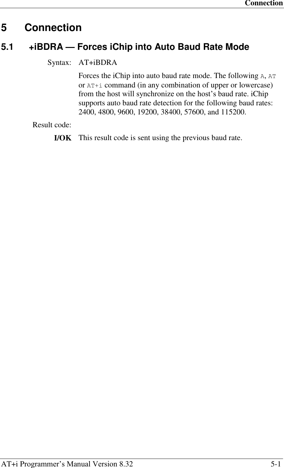
![Connection AT+i Programmer‘s Manual Version 8.32 5-2 5.2 +iUP — Initiate Internet Session Syntax: AT+iUP[:n] Initiates an Internet session by going online. In a dialup/cellular environment, a PPP Internet connection is established. Once online, optionally goes through an IP registration process, as determined by n. Parameters: n=0..1 Default: n=0 Command Options: n=0 Go online. n=1 Go online and carry out the IP registration process according to the relevant registration option parameters. Result Code: I/ONLINE After successfully establishing an Internet session and completing the IP registration (if requested). I/ERROR If iChip cannot go online and establish an Internet session or cannot complete the requested IP registration.](https://usermanual.wiki/Connect-One/SM2144N1/User-Guide-1162098-Page-38.png)
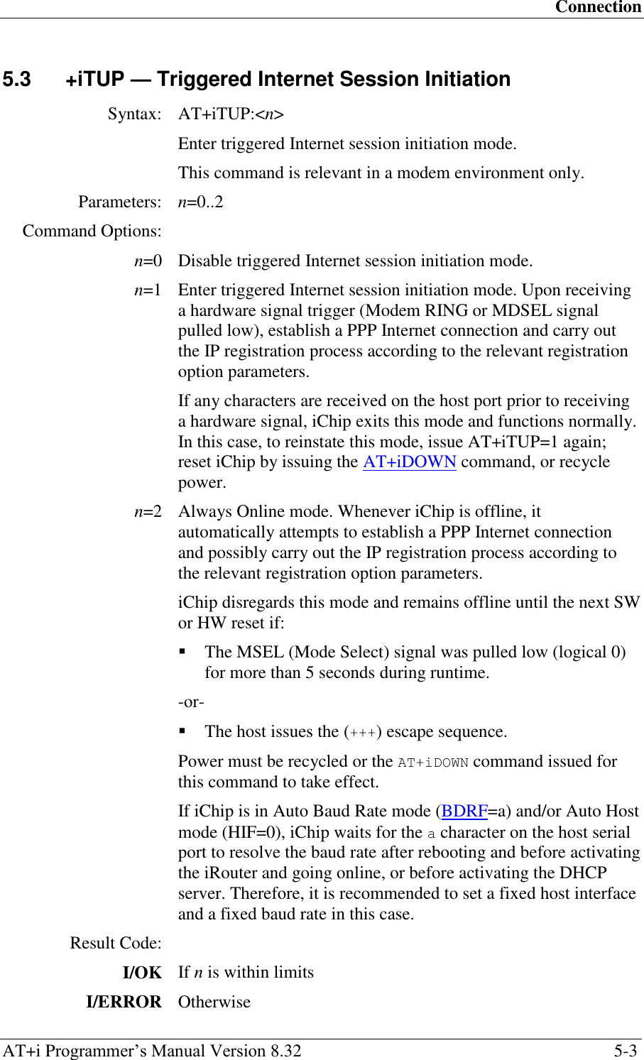
![E-mail Send Commands AT+i Programmer‘s Manual Version 8.32 6-1 6 E-mail Send Commands 6.1 +iEMA — Accept ASCII-Coded Lines for E-Mail Send Syntax: AT+i[!]EMA:<text lines> Defines a plain text e-mail body. Parameters: <text lines> Plain text e-mail body. The e-mail body contains <CR/LF> terminated ASCII character strings. <text lines> must be terminated by a dot character (.) in the 1st column of an otherwise empty line. Command Options: <text lines>::={<ASCII text line><CRLF> …}<CRLF>.<CRLF> Maximum size of <text lines> is limited to 18K, provided that no additional system resources are in use. EMA uses the specified SMTP server to send the e-mail message. When iChip acquires TOD from a network timeserver, outgoing e-mail messages are time and date stamped. ! Stay online after completing the command Result Code: I/OK After all text lines are received and terminated by the (.) line. I/ERROR If memory overflow occurred before all text lines are received. Followed by: I/DONE After successfully sending the e-mail. Allow a 2.5 seconds delay for iChip re-initialization following an Internet mode session. -or- I/ONLINE After successfully sending the e-mail, if the stay online flag (!) is specified. -or- I/ERROR If some error occurred during the send session.](https://usermanual.wiki/Connect-One/SM2144N1/User-Guide-1162098-Page-43.png)
![E-mail Send Commands AT+i Programmer‘s Manual Version 8.32 6-2 6.2 +iEMB — Accept Binary Data for Immediate E-Mail Send Syntax: AT+i[!]EMB[#]:<sz>,<data> Defines and sends a MIME-encoded binary e-mail. Parameters: <sz> size of <data> in bytes <data> <sz> bytes of binary data Command Options: <sz> 0..4GB <data> 8 bit binary data. Must be exactly <sz> bytes long. The binary data is encapsulated in a MIME-encoded e-mail message. The receiving end views the binary data as a standard e-mail attachment. Several consecutive +iEMB commands can be issued in sequence to create a larger aggregate of data to be sent. The e-mail contents are completed by issuing an AT+iE* (terminate binary e-mail) command. Following the first +iEMB command, iChip establishes an Internet connection while the data stream is being transmitted from the host. Once an SMTP session is established, iChip maintains a data transmit pipeline between the host and the SMTP server. iChip converts the binary data using BASE64 encoding on-the-fly. Following this command, the Internet session remains active to service additional +iEMB commands, until the +iE* terminating command. EMB uses the specified SMTP server to send the e-mail message. When iChip acquires TOD from a network timeserver, outgoing e-mail messages are time and date stamped. ! Stay online after completing the command. This flag is redundant, as the iChip defaults to staying online until the AT+iE* command is issued. # Modem baud rate limit flag. When this character is included in the command, the iChip baud rate to the modem is limited by the baud rate from the host. This flag is relevant for serial modems only and is especially useful in GSM modem configurations. When this character is not present, the iChip attempts to lift the baud rate to the modem to its maximal value. Result Code:](https://usermanual.wiki/Connect-One/SM2144N1/User-Guide-1162098-Page-44.png)
![E-mail Send Commands AT+i Programmer‘s Manual Version 8.32 6-4 6.3 +iE* — Terminate Binary E-Mail Syntax: AT+i[!]E* Terminates the current binary e-mail attachment. Command Options: ! Stay online after completing the command Result Code: I/OK If a binary e-mail attachment is in the process of being defined. The e-mail message is terminated and the SMTP session is then completed and closed. I/ERROR Otherwise Followed by: I/DONE After successfully sending the e-mail. Allow a 2.5 seconds delay for iChip re-initialization following an Internet mode session. -or- I/ONLINE After successfully sending the e-mail, if the stay online flag (!) is specified. -or- I/ERROR If some error occurred during the send session.](https://usermanual.wiki/Connect-One/SM2144N1/User-Guide-1162098-Page-46.png)
![E-Mail Retrieve AT+i Programmer‘s Manual Version 8.32 7-1 7 E-Mail Retrieve 7.1 +iRML — Retrieve Mail List Syntax: AT+i[!]RML Retrieves pending e-mail list from current mailbox. Command Options: ! Stay online after completing the command Result Code: I/OK To acknowledge successful receipt of the command. I/ERROR Otherwise Returns: I/MBE If the mailbox is empty. Otherwise: A list of qualifying e-mail message descriptors, separated by <CR/LF>. An e-mail message descriptor is composed of 5 <TAB> separated fields: <i><TAB><sz><TAB><date><TAB><sbjct string> <TAB><type/subtype><CR/LF> where, <i> - E-mail message index in mailbox <sz> - E-mail message size in bytes <date> - E-mail message date (for the date field format refer to RFC822) <sbjct string> - E-mail message subject string (limited to 128 bytes) <type/subtype> - MIME content type. The literal NONE is used for non-MIME e-mail messages. E-mail messages that qualify the E-Mail Delete Filter (DELF) are not listed. Followed by: I/DONE After successfully retrieving the e-mail list. Allow a 2.5 seconds delay for iChip re-initialization following an Internet mode session. -or- I/ONLINE After successfully retrieving the e-mail list, if the stay online flag (!) is specified. I/ERROR Otherwise](https://usermanual.wiki/Connect-One/SM2144N1/User-Guide-1162098-Page-47.png)
![E-Mail Retrieve AT+i Programmer‘s Manual Version 8.32 7-2 7.2 +iRMH — Retrieve Mail Header Syntax: AT+i[!]RMH[:i] Retrieves header of e-mail message <i> from current mailbox. Parameters: i Optional e-mail message index of a qualifying message. If no parameter is used, all e-mail headers are retrieved. Command Options: i Optional index of a qualifying message, as reported by AT+iRML. ! Stay online after completing the command Default: Retrieves headers of all pending qualified mail messages. Result Code: I/OK When command is received and about to be processed. I/ERROR Otherwise Returns: I/MBE If the mailbox is empty. Otherwise: All header lines of all qualifying e-mail messages. Header lines are returned as-is. A line containing solely a (.) (period) in column 1 acts as a separator between the header lines of each e-mail. The HDL parameter limits the number of header lines per mail (HDL=0 specifies an unlimited number of lines per e-mail). Header field syntax is described in RFC822 and RFC2045. Followed by: I/DONE After successfully retrieving the e-mail headers. Allow a 2.5 seconds delay for iChip re-initialization following an Internet mode session. -or- I/ONLINE After successfully retrieving the e-mail headers, if the stay online flag (!) is specified. -or- I/ERROR Otherwise](https://usermanual.wiki/Connect-One/SM2144N1/User-Guide-1162098-Page-48.png)
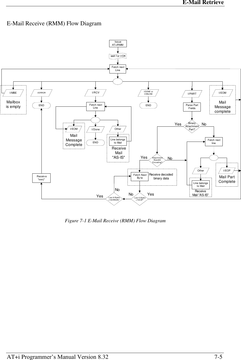
![E-Mail Retrieve AT+i Programmer‘s Manual Version 8.32 7-3 7.3 +iRMM — Retrieve Mail Message Syntax: AT+i[!]RMM[:i] Retrieves contents of e-mail message i from current mailbox. Parameters: i Optional e-mail message index of a qualifying message. If no parameter is used, all e-mails are retrieved. Command Options: i Optional index of a qualifying message, as reported by AT+iRML. ! Stay online after completing the command. Default: Retrieves all pending qualified mail messages. Result Code: I/OK When command is received and about to be processed. I/ERROR Otherwise Returns: I/MBE If the mailbox is empty. Otherwise: For each e-mail part: (For plain-text e-mails without MIME attachments) I/PART – <text><TAB><plain><TAB><TAB> <quoted-printable><CR/LF> -or- (For e-mails containing MIME attachments) I/PART – <media type><TAB><media subtype><TAB> <filename><TAB> <encoding method><CR/LF> -or- (When XFH – transfer e-mail headers – is set to YES) I/RCV -or- Followed by: <e-mail message contents> If the XFH parameter (transfer e-mail headers) is set to YES, all e-mail contents are returned as-is. The e-mail‘s headers followed by the e-mail‘s body are retrieved. MIME encapsulated e-mail messages are retrieved without BASE64 decoding. It is assumed that when the XFH parameter is set to YES, the host processor attends to all e-mail field parsing and contents decoding. If the XFH parameter is set to NO, only the](https://usermanual.wiki/Connect-One/SM2144N1/User-Guide-1162098-Page-49.png)
![HTTP Client Interface AT+i Programmer‘s Manual Version 8.32 8-1 8 HTTP Client Interface 8.1 +iRLNK — Retrieve Link Syntax: AT+i[!]RLNK[:URL] Retrieves a file from a URL. Parameters: URL = Optional URL address, which specifies the host, path, and source file to be retrieved. URL address syntax: ―<protocol>://<host>[[:<port>]/[<abs_link>]/]‖ Command Options: <protocol> http or https <host> Host name or IP address <port> 0..65535 If not specified, defaults to 80 for http and 443 for https. <abs_link> Path, filename, and file extension of the file to retrieve on the designated host. ! Stay online after completing the command. Default: Uses the URL address stored in the URL parameter. Result Code: I/OK When command is received and about to be processed. I/ERROR Otherwise Returns: I/<sz><CR><LF> Followed by: <binary data stream> where, <sz> is the exact size of the <binary data stream> to follow. If <sz> is unknown, iChip returns I/0 followed by the data stream. When this is the case, the host must monitor for a timeout condition of at least 5 seconds without any data being transmitted before seeing one of the terminator lines described under ‗Followed by‘. Followed by: I/DONE After successfully retrieving the file. Allow a 2.5 seconds delay for iChip re-initialization following an Internet mode session. -or- I/ONLINE After successfully retrieving the file, if the stay online flag (!) is](https://usermanual.wiki/Connect-One/SM2144N1/User-Guide-1162098-Page-52.png)
![HTTP Client Interface AT+i Programmer‘s Manual Version 8.32 8-3 8.2 +iSLNK — Submit A POST Request to A Web Server Syntax: AT+i[!]SLNK:<text> Submits a plain text POST request to a web server defined in the URL parameter. The ―Content-type:‖ field of the POST request is defined by the CTT parameter. Parameters: <text> = Plain text POST request body containing <CR[LF]> terminated ASCII character strings. <text> must be terminated by a dot character (.) in the first column of an otherwise empty line. Command Options: <text> <ASCII text line><CRLF> …<CRLF>.<CRLF> Maximum size of <text> depends on the amount of memory available in the specific iChip. SLNK uses the URL address stored in the URL parameter to send the POST request. ! Stay online after completing the command. Result Code: I/OK After all text lines are received from the host. I/ERROR If a memory overflow occurred before all text lines are received.](https://usermanual.wiki/Connect-One/SM2144N1/User-Guide-1162098-Page-54.png)
![SerialNET Mode Initiation AT+i Programmer‘s Manual Version 8.32 9-1 9 SerialNET Mode Initiation 9.1 +iSNMD — Activate SerialNET Mode Syntax: AT+i[! | @]SNMD Activates SerialNET mode. Instead of using the optional (!) and (@) flags, you can use the following syntax: AT+iSNMD=1 is equivalent to AT+iSNMD AT+iSNMD=2 is equivalent to AT+i!SNMD AT+iSNMD=3 is equivalent to AT+i@SNMD AT+iSNMD=4 causes iChip to enter SerialNET-over-TELNET mode Command Options: AT+i!SNMD -or- AT+iSNMD=2 Optional Auto-Link mode. When this flag is specified, iChip immediately goes online when activating SerialNET mode (even when serial data has not yet arrived). If the LPRT (Listening Port) parameter is defined, iChip opens the listening port and awaits a connection. If LPRT is not defined, but HSRV (Host Server) is defined, iChip immediately opens a SerialNET socket link to the server. AT+i@SNMD -or- AT+iSNMD=3 Optional Deferred Connection mode. When this flag is specified, iChip automatically goes online (as in the case of AT+i!SNMD). However, if the HSRV parameter is defined, a socket is not opened until data arrives on the local serial port. If the SerialNET mode listening port is defined (LPRT), iChip opens a listening socket and waits for a remote connection during the idle period before data arrives on the local serial port. When the SerialNET socket type (STYP) is TCP and serial data arrives, iChip buffers the data in the MBTB Buffer and tries to connect to HSR0. If HSR0 does not respond, iChip tries HSR1, then HSR2. If all three connection attempts fail, iChip retries them all. After three full retry cycles, iChip dumps the MBTB buffer and remains idle until new serial data arrives. AT+iSNMD=4 Optional SerialNET over TELNET mode. In this mode, iChip opens a data socket as a TELNET socket, which allows negotiations of TELNET options over the same socket while the host is sending and receiving raw data only. This mode partially supports the RFC2217 standard. For more information about this mode, refer to the SerialNET over TELNET description.](https://usermanual.wiki/Connect-One/SM2144N1/User-Guide-1162098-Page-55.png)
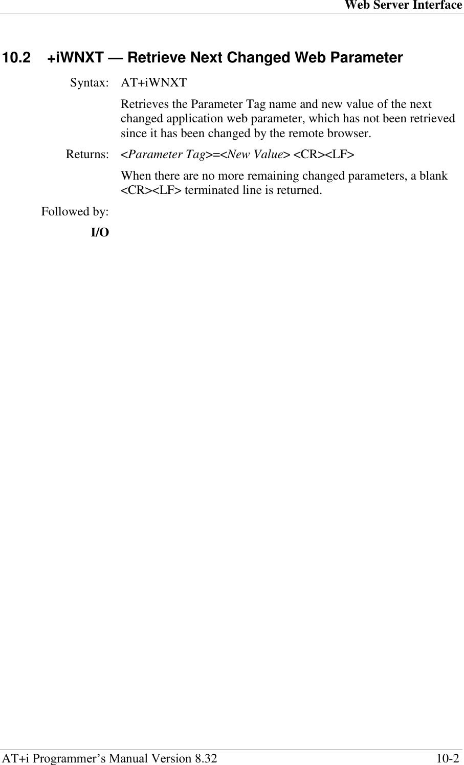
![Web Server Interface AT+i Programmer‘s Manual Version 8.32 10-1 10 Web Server Interface 10.1 +iWWW — Activate Embedded Web Server Syntax: AT+iWWW[:n] Activates iChip‘s internal web server. Parameters: <n>=Web browser backlog. n represents the number of browsers that can connect to iChip‘s internal web server simultaneously at any given time. Command Options: <n>=1..3 Default: <n>=1 Returns: I/(<Local IP addr>) where, <Local IP addr> is the iChip local IP address. Note: If the web server is already open, then I/(<Local IP addr>) is returned without any action taken. In a dial-up environment, iChip goes online and the <local IP addr> is assigned dynamically by the ISP. In an LAN environment, the IP address is assigned by a DHCP server or configured by the DIP parameter. I/ERROR If connection to the Internet failed.](https://usermanual.wiki/Connect-One/SM2144N1/User-Guide-1162098-Page-57.png)
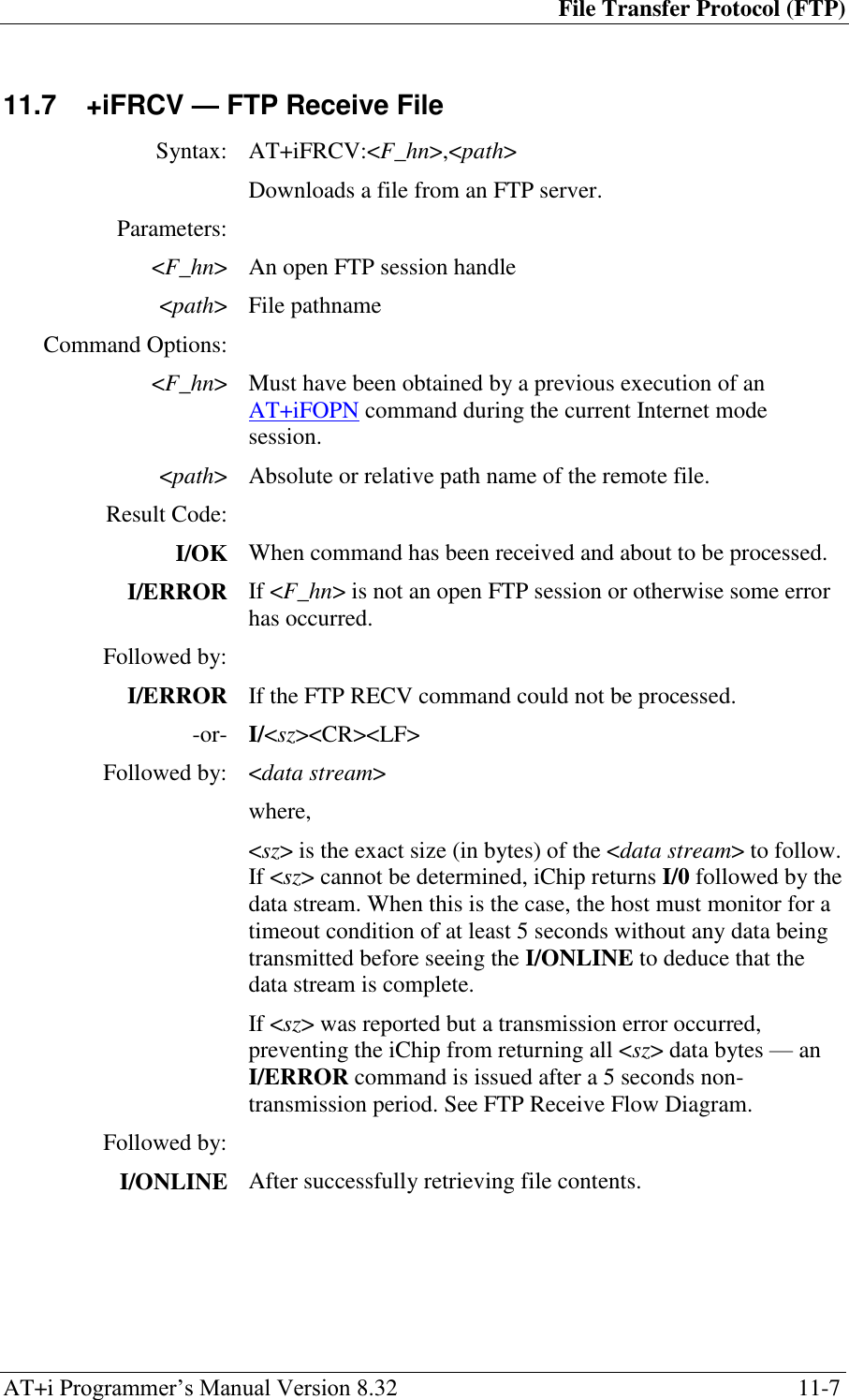
![File Transfer Protocol (FTP) AT+i Programmer‘s Manual Version 8.32 11-1 11 File Transfer Protocol (FTP) 11.1 +i[@]FOPN — FTP Open Session Syntax: AT+i[@]FOPN:<server>[,<port>]:<user>,<pass>[,<accnt>] Opens an FTP link to an FTP server. Parameters: <server> Logical name of the FTP or the server‘s IP address. <port> Optional FTP port in the range 0..65535. <user> FTP user‘s name <pass> FTP user‘s password <accnt> Optional FTP account Command Options: <server> The server name may be any legal Internet-server name, which can be resolved by the iChip‘s DNS (Domain Name Server) settings. The server name may also be specified as an absolute IP address given in DOT form. <port> Specifies the FTP server‘s listening port. If not specified, port 21 (decimal) is assumed. <user> User‘s name string. This must be a registered user on the FTP server. Some servers allow anonymous login, in which case user=anonymous. <pass> Password to authenticate user. If special characters are used, the password must be specified within quotes. It is customary that servers that allow anonymous login request an e-mail address as a password. <accnt> Some FTP servers require an account in order to allow a certain subset of the commands. In this case, the account name must be specified when opening the FTP link. @ The optional @ is used to flag the Force PASV mode. When @ is specified, iChip only uses the PASV method when opening a data socket to server for FTP data transfer. Result Code: I/<FTP handle> Upon successfully connecting to the FTP Server and authenticating the user, a socket handle is returned. The handle <FTP handle> is used to reference the FTP session in all following FTP commands. I/ERROR Otherwise](https://usermanual.wiki/Connect-One/SM2144N1/User-Guide-1162098-Page-59.png)
![File Transfer Protocol (FTP) AT+i Programmer‘s Manual Version 8.32 11-2 11.2 +iFDL — FTP Directory Listing Syntax: AT+iFDL:<F_hn>[,<path>] Returns a full FTP directory listing. Parameters: <F_hn> An open FTP session handle <path> Directory or filename wild card Command Options: <F_hn> Must have been obtained by a previous execution of an AT+iFOPN command during the current Internet mode session. <path> Optional directory name or filename wild card. If <path> is a directory, that directory‘s files are listed. If it is a filename wild card, only matching filenames in the current directory are listed. If <path> is not specified, the current directory is listed in full. Result Code: I/OK To acknowledge successful receipt of the command. I/ERROR If <F_hn> is not an open FTP session or otherwise some error has occurred. Returns: A list of filenames with file attributes. Each file is listed on a separate line, terminated by <CR/LF>. The file data line syntax is FTP server-dependant. Followed by: I/ONLINE After successfully retrieving the directory list.](https://usermanual.wiki/Connect-One/SM2144N1/User-Guide-1162098-Page-60.png)
![File Transfer Protocol (FTP) AT+i Programmer‘s Manual Version 8.32 11-3 11.3 +iFDNL — FTP Directory Names Listing Syntax: AT+iFDNL:<F_hn>[,<path>] Returns the FTP directory name list. Parameters: <F_hn> An open FTP session handle <path> Optional directory or filename wild card Command Options: <F_hn> Must have been obtained by a previous execution of an AT+iFOPN command during the current Internet mode session. <path> Optional directory name or filename wild card. If <path> is a directory, that directory‘s files are listed. If it is a filename wild card, only matching filenames in the current directory are listed. If <path> is not specified, the current directory is listed in full. Result Code: I/OK To acknowledge successful receipt of the command. I/ERROR If <F_hn> is not an open FTP session or otherwise some error has occurred. Returns: A bare list of filenames. Each file name is listed on a separate line, terminated by <CR/LF>. No attributes are returned in addition to the filename. Followed by: I/ONLINE After successfully retrieving the directory list.](https://usermanual.wiki/Connect-One/SM2144N1/User-Guide-1162098-Page-61.png)
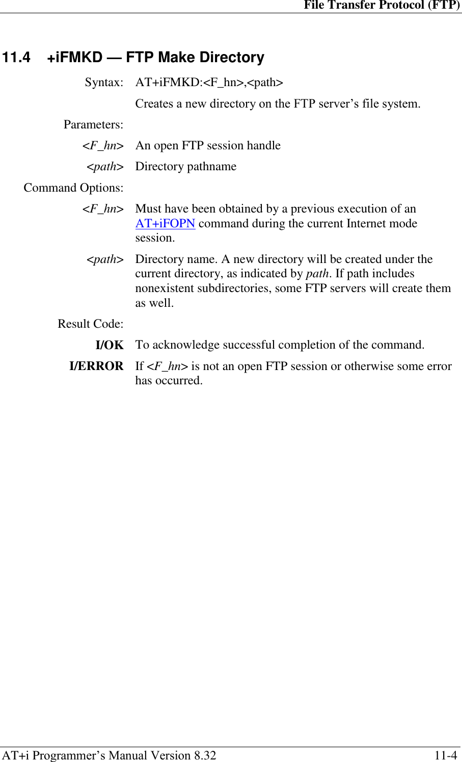
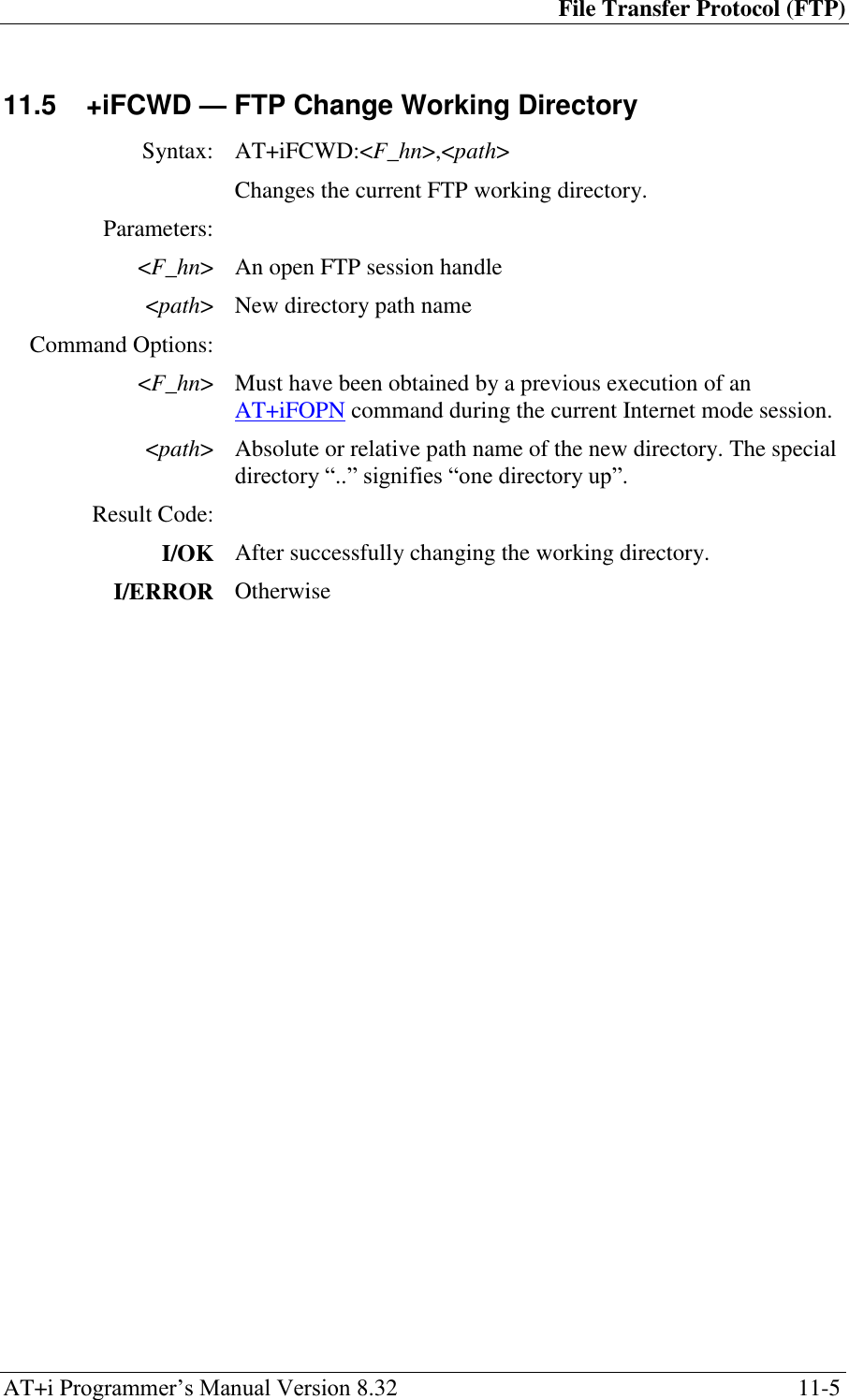
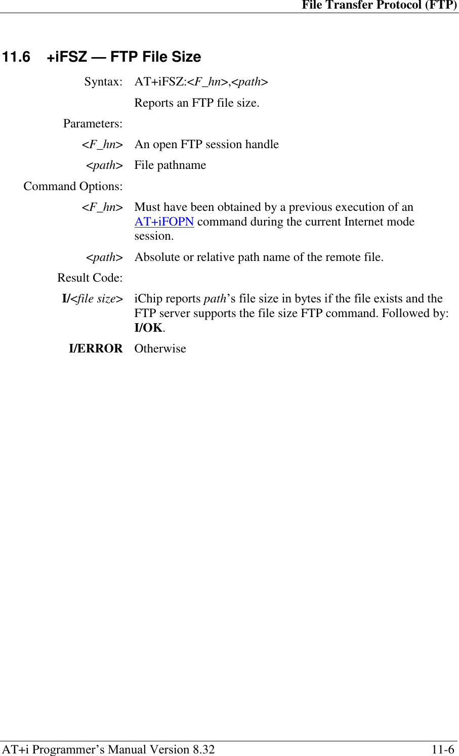
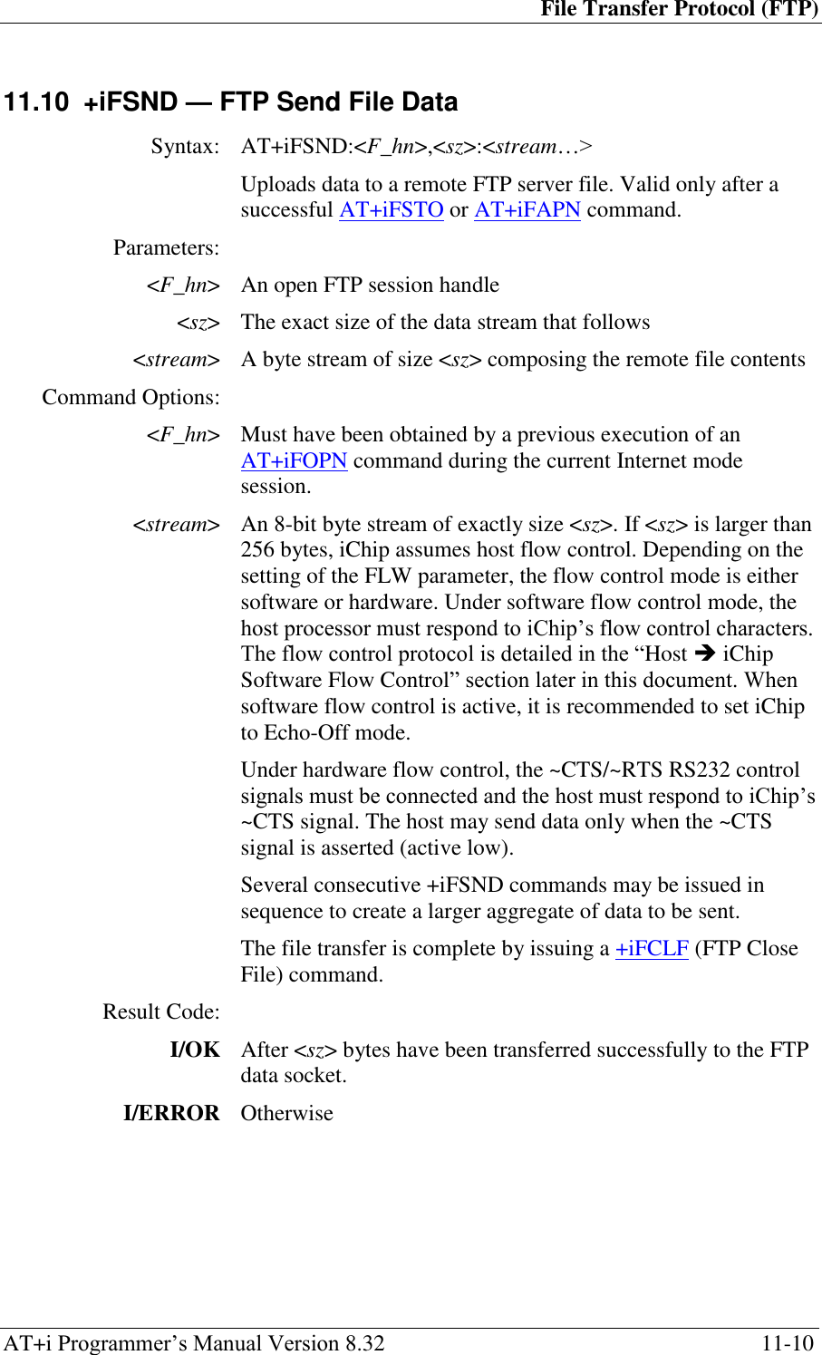
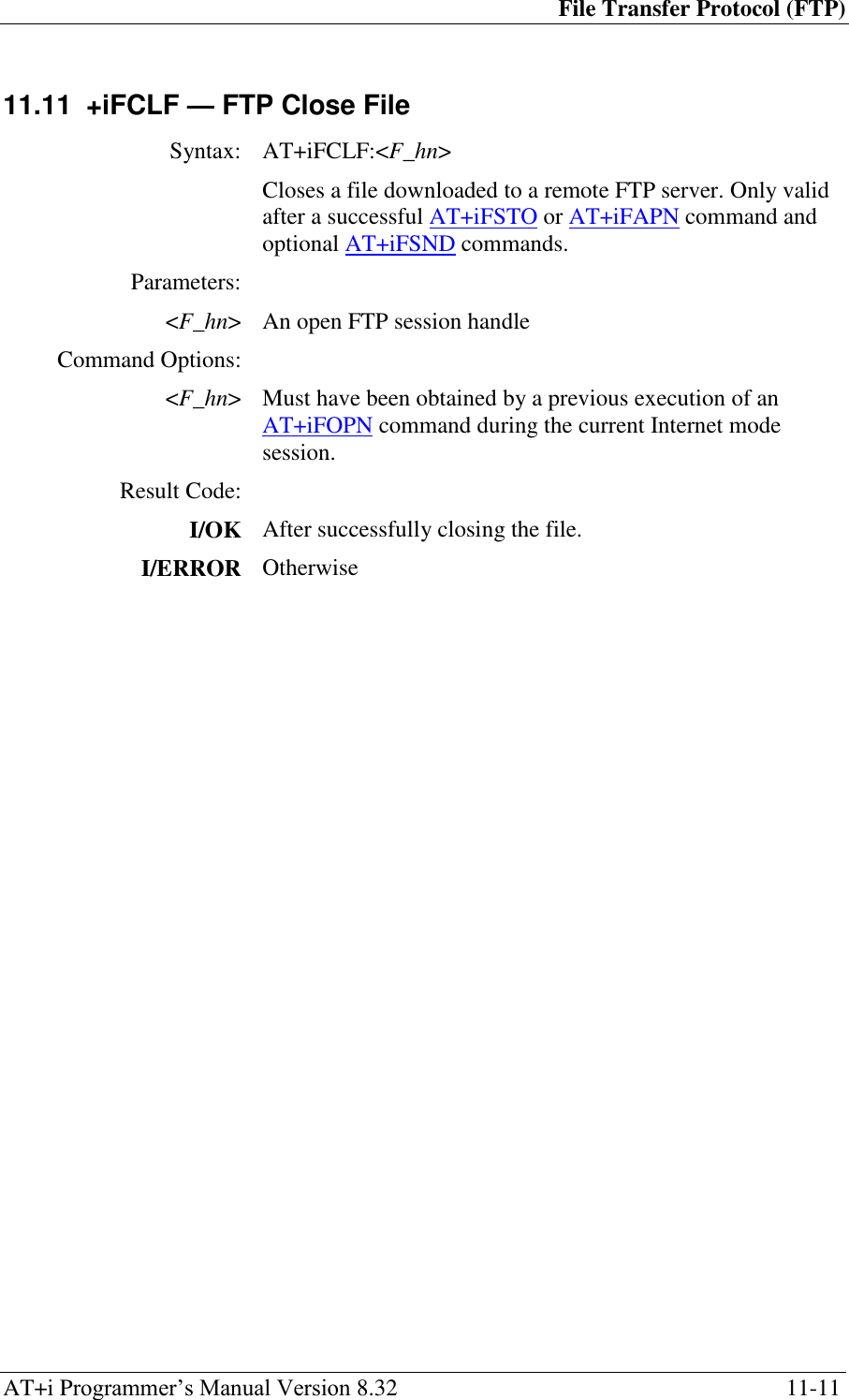
![File Transfer Protocol (FTP) AT+i Programmer‘s Manual Version 8.32 11-8 11.8 +iFSTO — FTP Open File for Storage Syntax: AT+iFSTO:<F_hn>,<path>[,<sz>] Opens a remote FTP server file for upload. Parameters: <F_hn> An open FTP session handle <path> Destination file pathname <sz> Optional size in bytes to reserve for the file on the remote FTP server Command Options: <F_hn> Must have been obtained by a previous execution of an AT+iFOPN command during the current Internet mode session. <path> Absolute or relative path name of the remote destination file. Following this command data is transferred to the remote file using one or more +iFSND commands. The file transfer is complete by issuing a +iFCLF (FTP File Close) command. Result Code: I/OK If file <path> was successfully opened for writing on the FTP server. I/ERROR Otherwise](https://usermanual.wiki/Connect-One/SM2144N1/User-Guide-1162098-Page-66.png)
![File Transfer Protocol (FTP) AT+i Programmer‘s Manual Version 8.32 11-9 11.9 +iFAPN — FTP Open File for Appending Syntax: AT+iFAPN:<F_hn>,<path>[,<sz>] Opens an existing remote FTP server file for Append. Parameters: <F_hn> An open FTP session handle <path> File pathname <sz> Size in bytes to reserve for the file on the server Command Options: <F_hn> Must have been obtained by a previous execution of an AT+iFOPN command during the current Internet mode session. <path> Absolute or relative path name of the remote destination file. Following this command data is transferred to the remote file using one or more +iFSND commands. The file transfer is complete by issuing a +iFCLF (FTP File Close) command. Result Code: I/OK If file <path> was successfully opened for appending on the FTP server. I/ERROR Otherwise](https://usermanual.wiki/Connect-One/SM2144N1/User-Guide-1162098-Page-67.png)
![File Transfer Protocol (FTP) AT+i Programmer‘s Manual Version 8.32 11-13 11.13 +iFCLS — FTP Close Session Syntax: AT+i[!]FCLS:<F_hn> Closes the FTP link. Parameters: <F_hn> An open FTP session handle Command Options: <F_hn> Must have been obtained by a previous execution of an AT+iFOPN command during the current Internet mode session. ! Stay online after completing the command Result Code: I/OK When command has been received and about to be processed. Followed by: I/DONE When the FTP link was the last open socket and after successfully closing the FTP link. Allow a 2.5 seconds delay for iChip re-initialization following an Internet mode session. -or- I/ONLINE After successfully closing the FTP link, when additional sockets are still active or the stay online flag (!) is specified. -or- I/ERROR Otherwise](https://usermanual.wiki/Connect-One/SM2144N1/User-Guide-1162098-Page-71.png)
![Telnet Client AT+i Programmer‘s Manual Version 8.32 12-2 12.2 +iTRCV — Telnet Receive Data Syntax: AT+iTRCV[:<max>] Receives data from the Telnet server. Parameters: <max> Optionally specifies the maximum number of bytes to transfer. Result Code: I/ERROR If no Telnet session is open or otherwise some error has occurred. Returns: I/<sz>[:<binary data stream>] where, <sz> is the exact size of the binary data stream to follow. If the socket input buffer is empty, iChip returns I/O. In this case the (:) and <binary data stream> are omitted. <sz> is guaranteed to be equal or less than <max>, when specified.](https://usermanual.wiki/Connect-One/SM2144N1/User-Guide-1162098-Page-73.png)
![Telnet Client AT+i Programmer‘s Manual Version 8.32 12-4 12.4 +iTBSN[%] — Telnet Send A Byte Stream Syntax: AT+iTBSN[%]:<sz>:<stream> Sends a byte stream of size <sz> to the Telnet server. Parameters: <sz> The exact size of the byte stream that follows. <stream> A byte stream of size <sz> to be sent to the Telnet server. Command Options: <sz> 0..4GB <stream> An 8-bit byte stream of exactly size <sz>. If <sz> is larger than 256 bytes, iChip assumes host flow control. Depending on the setting of the FLW parameter, the flow control mode is either software or hardware. Under software flow control mode, the host processor must respond to iChip‘s flow control characters. The flow control protocol is detailed in the ―Host iChip Software Flow Control‖ section later in this document. Under hardware flow control, the ~CTS/~RTS RS232 control signals must be connected and the host must respond to iChip‘s ~CTS signal. The host may send data only when the ~CTS signal is asserted (active low). % When the auto-flush (‗%‘) flag is specified, the Telnet socket is automatically flushed immediately after receiving the <stream> from the host. Otherwise, data will be transmitted to the Internet only in integral quantities of the specified Maximum Transfer Unit (MTU) or when the AT+iTFSH command is issued. Result Code: I/OK After <sz> bytes have been transferred successfully to the Telnet socket‘s output buffer. I/ERROR Otherwise](https://usermanual.wiki/Connect-One/SM2144N1/User-Guide-1162098-Page-75.png)
![Telnet Client AT+i Programmer‘s Manual Version 8.32 12-5 12.5 +iTFSH[%] — Flush Telnet Socket’s Outbound Data Syntax: AT+iTFSH[%] Flushes (immediately sends) all the data accumulated in a Telnet socket‘s outbound buffer. Command Options: % When the flush-and-acknowledge (‗%‘) flag is specified, iChip flushes and waits for the Telnet server receipt acknowledgment of all outstanding outbound data. Result Code: I/OK If all outbound data has been received and acknowledged by the Telnet server. I/ERROR Otherwise](https://usermanual.wiki/Connect-One/SM2144N1/User-Guide-1162098-Page-76.png)
![Telnet Client AT+i Programmer‘s Manual Version 8.32 12-6 12.6 +iTCLS — Telnet Close Session Syntax: AT+i[!]TCLS Closes the Telnet link. Command Options: ! Stay online after completing the command Result Code: I/OK If an active Telnet socket exists. Followed by: I/DONE When the Telnet link was the last open socket and after successfully closing the Telnet link. Allow a 2.5 seconds delay for iChip re-initialization following an Internet mode session. -or- I/ONLINE After successfully closing the Telnet link, when additional sockets are still active or the stay online flag (!) is specified. -or- I/ERROR Otherwise](https://usermanual.wiki/Connect-One/SM2144N1/User-Guide-1162098-Page-77.png)
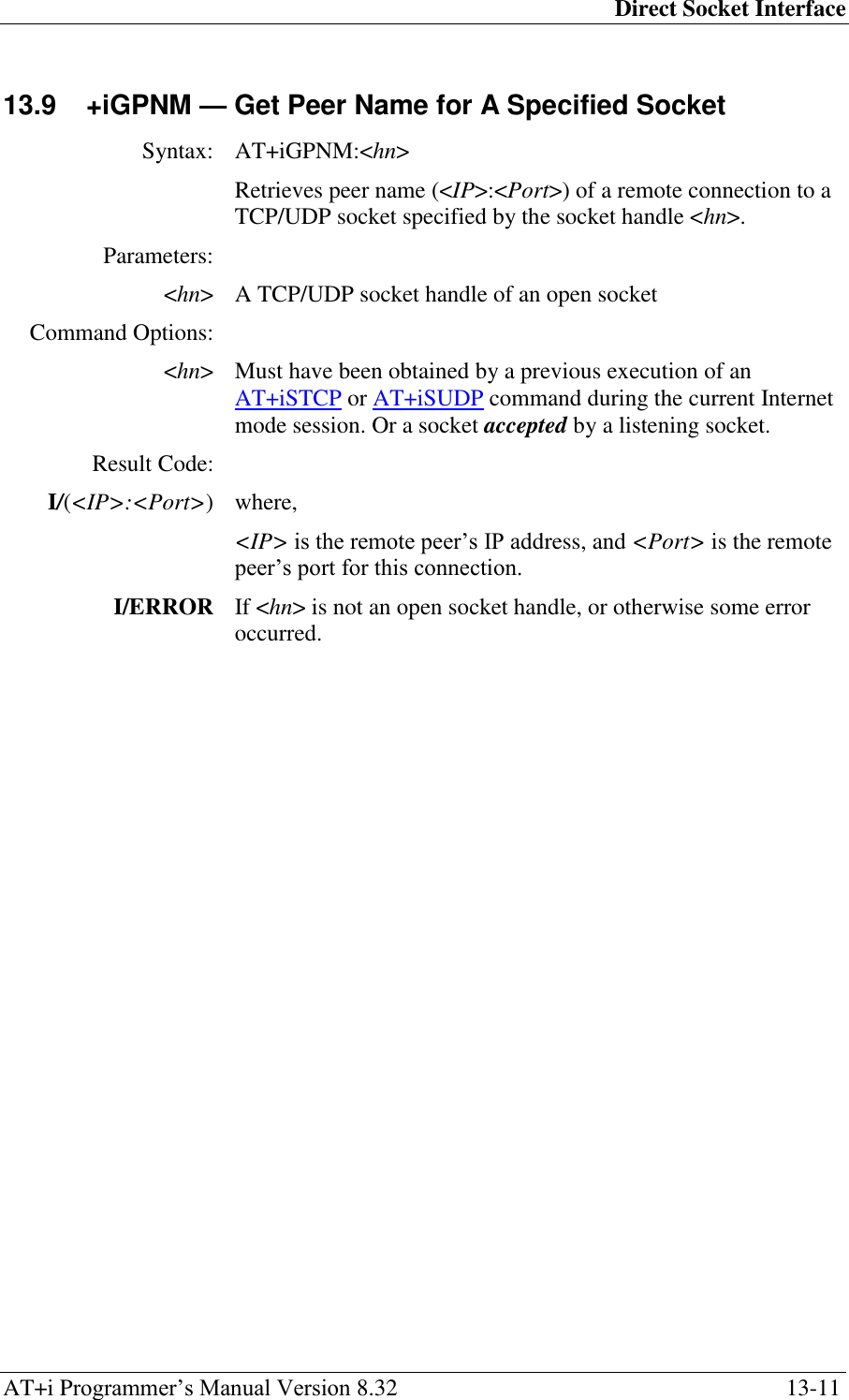
![Direct Socket Interface AT+i Programmer‘s Manual Version 8.32 13-1 13 Direct Socket Interface 13.1 +iSTCP — Open and Connect A TCP Socket Syntax: AT+iSTCP:<host>,<port>[,<lport>] Opens a Transmission Control Protocol (TCP) client socket and attempts to connect it to the specified <port> on a server defined by <host>. Parameters: <host> Logical name of the target server or a host IP address <port> 0..65535, target port <lport> Optional local port on iChip Command Options: <host> The server name may be any legal Internet server name that can be resolved by iChip‘s DNS (Domain Name Server) settings. The server name can also be specified as an absolute IP address given in DOT form. <port> It is assumed that the server system is listening on the specified port. <lport> Can be optionally specified to force iChip to use lport as the local port when opening the TCP socket. If unspecified, iChip allocates a port from its internal pool1. Result Code: I/<sock handle> Upon successfully opening and connecting the TCP socket to the <host>:<port>, a socket handle is returned. The socket handle <sock handle> is in the range 0..9 and used to reference the socket in all following socket commands. I/ERROR Otherwise The Socket Command Abort may be used to abort prematurely. 1Note: iChip uses the port range [1025 .. 2048] when assigning default local ports. The host should refrain from specifying local ports in this range to ensure that Error 218 is not generated as a result of requesting local ports that overlap internal assignments.](https://usermanual.wiki/Connect-One/SM2144N1/User-Guide-1162098-Page-78.png)
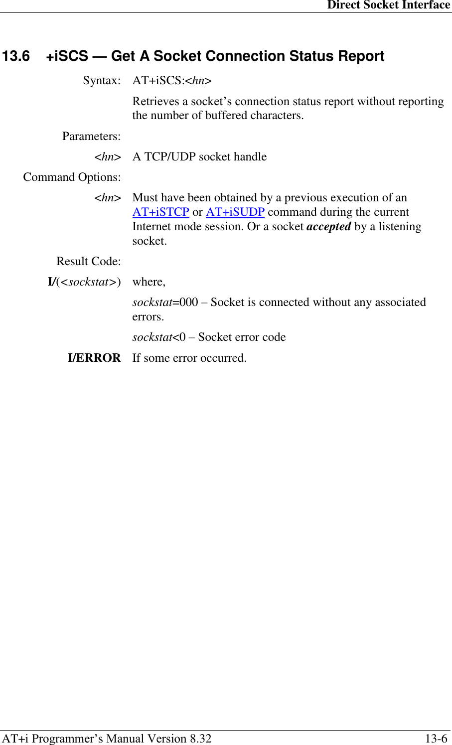
![Direct Socket Interface AT+i Programmer‘s Manual Version 8.32 13-2 13.2 +iSUDP — Open A Connectionless UDP Socket Syntax: AT+iSUDP:<host>,<rport>[,<lport>] Opens a UDP (User Datagram Protocol) socket and sets the remote system‘s <host>:<port> address. Parameters: <host> Logical name of the target server or a host IP address, or 0.0.0.0 to open a non-connected socket. <rport> Remote port number to send to, or 0 to open a non-connected socket. <lport> Optional local UDP port to use. Command Options: <host> The remote system‘s name may be any legal Internet server name that can be resolved by iChip‘s DNS (Domain Name Server) settings. The server name may also be specified as an absolute IP address given in DOT form. When the <host> is defined, the resulting UDP socket is created and connected. If <host>=0.0.0.0, the socket is created but remains unconnected. The first UDP packet to arrive automatically latches the sender‘s IP port, in effect connecting the socket. <rport> Specifies the remote system‘s port. <lport> Specifies the local port to use. If unspecified, iChip allocates a port from its internal pool. Result Code: I/<sock handle> Upon successfully opening and connecting the UDP socket to <host>:<port>, a socket handle is returned. The socket handle <sock handle> is in the range 0..9 and used to reference the socket in all following socket commands. I/ERROR Otherwise The Socket Command Abort may be used to abort prematurely.](https://usermanual.wiki/Connect-One/SM2144N1/User-Guide-1162098-Page-79.png)
![Direct Socket Interface AT+i Programmer‘s Manual Version 8.32 13-7 13.7 +iSSND[%] — Send A Byte Stream to A Socket Syntax: AT+iSSND[%]:<hn>,<sz>:<stream>[<checksum>] Sends a byte stream of size sz to the socket specified by the socket handle hn. Parameters: <hn> A TCP/UDP socket handle of an open socket <sz> The exact size of the byte stream that follows <stream> A byte stream of size sz to be sent to the specified socket. When iChip is in checksum mode (CKSM set to 1), the socket is UDP or when sending data over an SSL socket, sz is limited to 2048 bytes. <checksum> A two-byte checksum. Checksum is calculated by summing all the characters in stream modulo 65536 and taking two‘s complement of the result. Checksum is sent as big-endian. This parameter must be appended by the host application when iChip is in checksum mode. Command Options: <hn> Must have been obtained by a previous execution of an AT+iSTCP or AT+iSUDP command during the current Internet mode session. Or a socket accepted by a listening socket. <sz> Regular TCP socket: 0..4GB SSL Socket, Checksum mode or UDP: 0..2048 <stream> An 8-bit byte stream of exactly size sz. If sz is larger than 256 bytes, iChip assumes host flow control. Depending on the setting of the FLW parameter, the flow control mode is either software or hardware. Under software flow control mode, the host processor must respond to iChip‘s flow control characters. The flow control protocol is detailed in the ―Host iChip Software Flow Control‖ section. Under hardware flow control, the ~CTS/~RTS RS232 control signals must be connected and the host must respond to iChip‘s ~CTS signal. The host may send data only when the ~CTS signal is asserted (active low). % When the auto flush (%) flag is specified for a TCP socket, the socket is automatically flushed immediately after receiving the stream. Otherwise, data is transmitted to the Internet only in integral quantities of the specified Maximum Transfer Unit (MTU) or when the AT+iSFSH](https://usermanual.wiki/Connect-One/SM2144N1/User-Guide-1162098-Page-84.png)
![Direct Socket Interface AT+i Programmer‘s Manual Version 8.32 13-9 13.8 +iSRCV — Receive A Byte Stream from A Socket’s Input Buffer Syntax: AT+iSRCV:<hn>[,<max>] Receives a byte stream from the TCP/UDP socket specified by the socket handle hn. Received data is valid only if it already resides in iChip‘s socket input buffer at the time this command is issued. Parameters: <hn> A TCP/UDP socket handle of an open socket <max> Optionally specifies the maximum number of bytes to transfer. Additional bytes may remain in the socket input buffer following this command. Command Options: <hn> Must have been obtained by a previous execution of an AT+iSTCP or AT+iSUDP command during the current Internet mode session. Or a socket accepted by a listening socket. <max> If <max> is not specified, all available bytes residing in the socket input buffer are returned. Returns: I/<sz>[:<stream>][<checksum>] where, sz is the exact size of the binary data stream to follow. If the socket input buffer is empty, iChip returns I/O<CR><LF>. In this case, stream is omitted. sz is guaranteed to be equal or less-than max, when specified. checksum is a two-byte checksum. This parameter is calculated by iChip only when it is in checksum mode (CKSM set to ‗1‘). checksum is calculated by summing all the characters in stream modulo 65536 and taking two‘s complement of the result. checksum is sent as big-endian. The host application is assumed to calculate its own checksum upon receipt of stream and compare it against the checksum bytes received from iChip. If the two checksums don‘t match, the host can issue an AT+i!SRCV command, which causes iChip to re-transmit the data. The next AT+iSRCV command that the host issues causes iChip to dump all data transmitted to host in the previous AT+iSRCV command.](https://usermanual.wiki/Connect-One/SM2144N1/User-Guide-1162098-Page-86.png)

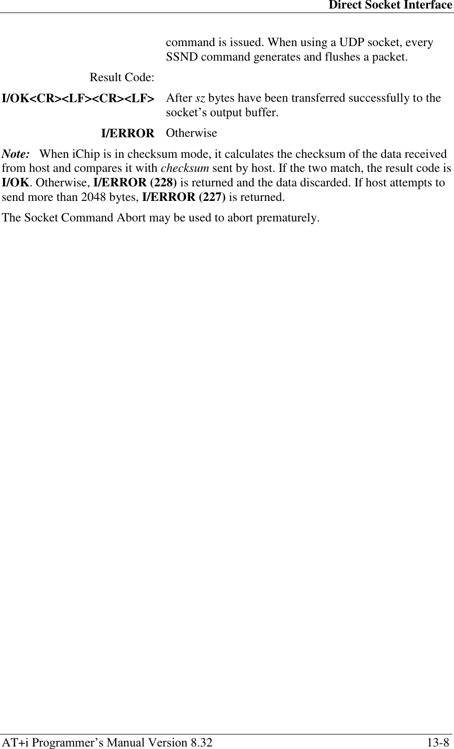
![Direct Socket Interface AT+i Programmer‘s Manual Version 8.32 13-13 13.11 +iSFSH[%] — Flush Socket’s Outbound Data Syntax: AT+iSFSH[%]:<hn> Flushes (immediately sends) accumulated data in a TCP socket‘s outbound buffer. Parameters: <hn> A TCP socket handle of an open socket Command Options: <hn> Must have been obtained by a previous execution of an AT+iSTCP command during the current Internet mode session. Or a socket accepted by a listening socket. % When the flush-and-acknowledge (%) flag is specified and <hn> is a TCP socket handle, iChip flushes and waits for the peer receipt acknowledgment of all outstanding outbound data. Common errors associated with this flag are 215 (carrier lost) and 203 (socket closed by peer in an orderly manner or did not receive ACK after repeated attempts to retransmit unacknowledged data). Result Code: I/OK If <hn> is a handle to an open socket and, when <hn> is a TCP socket handle, all outbound data has been received (and when (%) flag specified also acknowledged) by peer. I/ERROR Otherwise The Socket Command Abort may be used to abort prematurely.](https://usermanual.wiki/Connect-One/SM2144N1/User-Guide-1162098-Page-90.png)
![Direct Socket Interface AT+i Programmer‘s Manual Version 8.32 13-14 13.12 +iSCLS — Close Socket Syntax: AT+i[!]SCLS:<hn> Closes a TCP/UDP socket. If the socket is the only open socket and the stay online flag (!) is not specified, iChip terminates the Internet session and goes offline. Parameters: <hn> A TCP/UDP socket handle of an open socket Command Options: <hn> Must have been obtained by a previous execution of an AT+iLTCP, AT+iSTCP or AT+iSUDP command during the current Internet mode session. Or a socket accepted by a listening socket. A socket is always flushed before being closed. TCP sockets are disconnected from the remote host server in an orderly manner. ! Stay online after completing the command. Result Code: I/OK If <hn> is a handle to an open socket I/ERROR Otherwise Followed by: I/DONE After successfully closing the last open socket. Allow a 2.5 seconds delay for iChip re-initialization following an Internet mode session. -or- I/ONLINE After successfully closing the socket, while additional sockets are still open or if the stay online flag (!) is specified. -or- I/ERROR Otherwise](https://usermanual.wiki/Connect-One/SM2144N1/User-Guide-1162098-Page-91.png)
![Special Modem Commands AT+i Programmer‘s Manual Version 8.32 14-1 14 Special Modem Commands 14.1 +iMCM — Issue Intermediate Command to Modem Syntax: AT+iMCM[:<AT command>] Sends a single AT command to the modem during an internet session or enters Modem Command mode. Parameters: <AT command> Optional single AT command to be sent to modem. Command Options: <AT command> iChip puts the modem in command mode by issuing the (+++) escape sequence and then sends <AT command> to the modem, followed by a <CR>. <AT command> must include the AT prefix. After receiving the modem‘s response, iChip restores the modem to online operation mode by issuing the ATO command. If <AT command> is not specified, iChip enters Modem Command mode. In this mode, all following commands are transferred as-is to the modem. Modem replies are relayed back to the host processor. iChip does not translate the commands. Modem Command mode is exited after the host issues the ATO command. iChip transfers the ATO command to the modem and relays the modem‘s response back to the host. Returns: Modem‘s responses including command echo, if enabled. Followed by: I/OK When the modem successfully returns online. I/ERROR If modem was unable to go back online.](https://usermanual.wiki/Connect-One/SM2144N1/User-Guide-1162098-Page-92.png)


![Secure Socket Protocol AT+i Programmer‘s Manual Version 8.32 21-1 21 Secure Socket Protocol iChip supports the SSL3/TLS1 secure socket protocol, based on RFC2246. iChip supports the following Cipher suites: SSL_RSA_WITH_RC4_128_MD5 SSL_RSA_WITH_RC4_128_SHA SSL_RSA_WITH_3DES_EDE_CBC_SHA TLS_RSA_WITH_AES_128_CBC_SHA TLS_RSA_WITH_AES_256_CBC_SHA 21.1 Establishing An SSL3/TLS1 Socket Connection iChip supports a single SSL3/TLS1 TCP/IP active socket connection. Opening a secure socket on iChip involves two steps: 1. Open a standard TCP/IP socket to a secure server. 2. Initiate an SSL3/TLS1 handshake over the open socket to establish a secure session. SSL3/TLS1 handshake negotiations are initiated using the AT+iSSL command. iChip negotiates the secure connection based on several security-related parameters. It authenticates the remote secure server by verifying that the server‘s certificate is signed by a trusted Certificate Authority (CA). The trusted CA‘s certificate is stored in iChip‘s CA parameter. Following a successful SSL3/TLS1 handshake, iChip encrypts all data sent across the socket according to the cipher suite and keys agreed upon during the handshake. Data received on the socket is decrypted by iChip prior to making it available to the host processor. 21.2 Sending and Receiving Data over An SSL3/TLS1 Socket The AT+iSSND command is used to send data over an SSL3/TLS1 socket, using the same syntax as for non-secure sockets: AT+iSSND[%]:<hn>,<size>:<data> However, the size parameter is interpreted as the size of the data packet to encrypt. It is limited to 2K. Receiving data on an SSL3/TLS1 socket is carried out using the AT+iSRCV command. iChip automatically decrypts data that arrives on the secure socket. The data transferred to the host is always decrypted data. 21.3 SSL3/TLS1 Handshake and Session Example Take for example an SSL3/TLS1 server at secure.sslserver.com running a secure application on port 1503. Using iChip, the following sequence opens a secure SSL3/TLS1 socket to that application and exchanges data securely. For clarity, commands sent to iChip appear in bold and iChip replies appear in italics.](https://usermanual.wiki/Connect-One/SM2144N1/User-Guide-1162098-Page-115.png)
![Secure Socket Protocol AT+i Programmer‘s Manual Version 8.32 21-5 21.6 +i[@]FOPS — Secure FTP Open Session Syntax: AT+i[@]FOPS:<server>[,<port>]:<user>,<pass>[,<accnt>] Opens a secure FTP link to a secure FTP server. Parameters: <server> Logical name of the FTP server or the server‘s IP address. <port> Optional FTP port in the range 0-65535 <user> FTP user‘s name <pass> FTP user‘s password <accnt> Optional FTP account Command Options: <server> The server name may be any legal Internet server name that can be resolved by iChip‘s Domain Name Server (DNS) settings. The server name may also be specified as an absolute IP address given in DOT form. <port> Specifies the FTP server‘s listening port. If not specified, port 21 (decimal) is assumed. <user> User‘s name string. This must be a registered user on the FTP server. Some servers allow anonymous login, in which case user=anonymous. <pass> Password for user authentication. If special characters are used, the password must be specified within quotes. It is customary that servers that allow anonymous login request an e-mail address as a password. <accnt> Some FTP servers require an account in order to allow a certain subset of the commands. In this case, the account name must be specified when opening the FTP link. @ The optional @ is used to flag the Force PASV mode. When @ is specified, iChip uses only the PASV method when opening a data socket to server for FTP data transfer. Result Code: I/<FTP handle> Upon successfully connecting to the FTP server and authenticating the user, a socket handle is returned. The handle <FTP handle> is used to reference the FTP session in all subsequent FTP commands. I/ERROR Otherwise](https://usermanual.wiki/Connect-One/SM2144N1/User-Guide-1162098-Page-119.png)
![MIME Encapsulated E-Mail Messages AT+i Programmer‘s Manual Version 8.32 23-3 23.3 MIME-Encapsulated E-Mail Message Format Note: Bold lines are added by iChip. Received: from JFK by FTGate SmartPop; Tue, 23 Nov 1999 09:26:21 +0200 Received: from mail.inter.net.il (hrz-153-147.access.net.il [212.68.153.147]) by mail.inter.net.il (8.9.3/8.8.6/PA) with SMTP id OAA11594; Mon, 22 Nov 1999 14:18:03 +0200 (IST) Date: Mon, 22 Nov 1999 14:18:03 +0200 (IST) From: lims@connectone.com To: lims@connectone.com To: connect1@inter.net.il To: gadyl@netvision.net.il X-Mailer: iChip ic401d05 X-Serial: 123456 Return-Receipt-To: lims@connectone.com Message-ID: <15322@iChip> Subject: iChip binary message via iModem Mime-Version: 1.0 Content-Type: multipart/mixed; boundary=”CONE-iChip-ic401d05” X-UIDL: ad0c01ac458208bedea8b8522012e4b6 This MIME message was coded by iChip. --CONE-iChip-ic401d05 Content-Type: text/plain; charset=us-ascii Content-Transfer-Encoding: 7bit X-Coverpage: Email . <Textual body, here> . . --CONE-iChip-ic401d05 Content-Type: image/tiff; name="FaxImage.tif" Content-Transfer-Encoding: base64 . . . <Binary Base64-encoded data, here> . . . --CONE-iChip-ic401d05](https://usermanual.wiki/Connect-One/SM2144N1/User-Guide-1162098-Page-123.png)
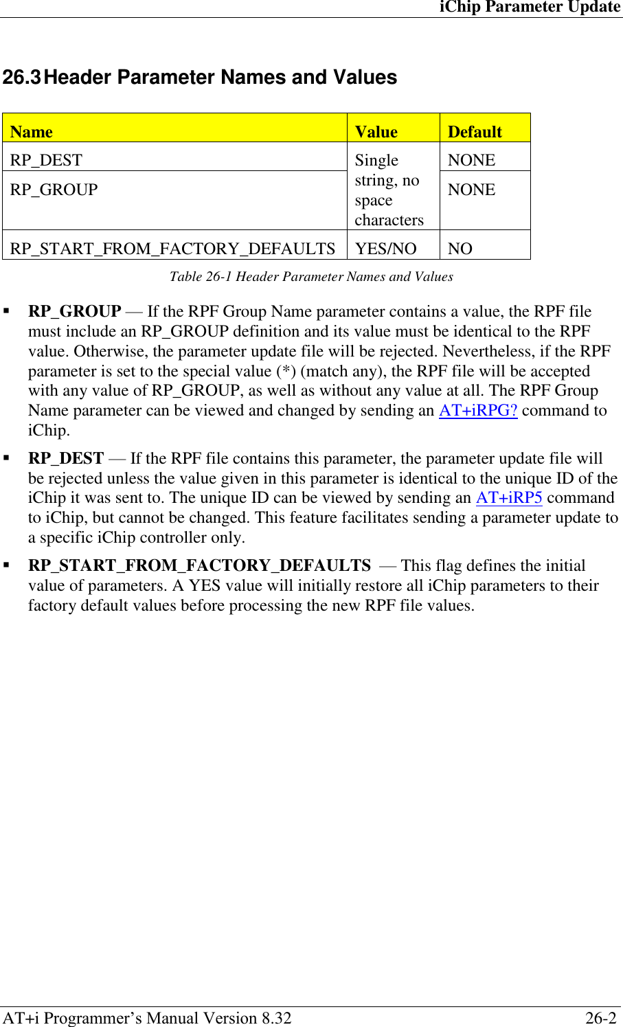
![iChip Parameter Update AT+i Programmer‘s Manual Version 8.32 26-1 26 iChip Parameter Update 26.1 Introduction The iChip remote parameter update file allows users to remotely modify various non-volatile parameters in iChip products. The file is an ASCII-formatted text file, edited by the user or created by a dedicated application. The file‘s size must not exceed 10k. The remote parameter file (RPF) naming convention is <filename>.rpf. If a parameter is assigned a legal value within the file, that value replaces the current value in iChip‘s non-volatile parameter database. A parameter value that is not referred to in the file, or that is not defined using the correct syntax rules, specified below, does not affect the current parameter value. 26.2 Remote Parameter File (RPF) Structure The RPFfile must include the letters ―RP_‖ as its first 3 characters, and can include additional header lines (defined below), as well as various parameter assignments. Assignments follow the rules defined for parameter settings, but excluding the AT+i prefix. For example, to assign the value myname to the POP3 mailbox name parameter, the correct assignment is MBX=myname This is equivalent to the host sending AT+iMBX=myname to iChip. Each line, terminated with <CR>/<LF>, can contain one assignment only. The order of assignments is not important, except for the RPF header parameters, which must be first and must follow the header definitions below. After the first non-RPF header parameter, additional header parameters are ignored. Comment lines can appear anywhere in the file. Comment line syntax is defined as: #<anything>CR/LF The first line in the file that is not a comment line is considered the authentication header line and must have the following syntax: RP_[GROUP=<string><space_character>][RP_DEST=<string>]CR/LF The remainder of the header must contain lines with the following syntax: <header_parameter_name>=<general_parameter_value>CR/LF](https://usermanual.wiki/Connect-One/SM2144N1/User-Guide-1162098-Page-133.png)
![iChip RAS Server AT+i Programmer‘s Manual Version 8.32 28-2 28.3 RAS Theory of Operation When a remote client dials into iChip, the modem RING strings are transferred by iChip (which defaults to transparent mode) to the host. When the RAS feature is enabled (RAU contains a value), iChip picks up the line and negotiates a PPP connection by issuing the ATA (modem) command after RAR RING strings have been received. If the host chooses to manage a direct (modem-to-modem) data connection, it can pick up the line before RAR RING strings have arrived by issuing the ATA modem command. During RAS PPP negotiations, iChip will replies only to (+++) (escape sequence) and AT+iRPn commands. Specifically, iChip replies ―Connecting as RAS‖ to the AT+iRP2 (iChip status) command. The escape sequence can be used to abort the RAS session at any time. The AT+iRP2 command is the only means for the host processor to determine that a PPP session is in progress. iChip manages the RAS protocol internally and does not transfer any information to the host. Any other commands received from the host are disregarded by iChip. Once the PPP connection has been fully negotiated and established, iChip responds to all AT+i commands as when it is online. Specifically, iChip replies ―RAS Connected‖ to the AT+iRP2 command. As part of the PPP negotiation, iChip assigns itself the default IP 192.168.0.1 and allocates 192.168.0.2 as the client IP. However, if the client requests a specific IP, iChip always grants the client‘s request and uses the client‘s IP minus 1 as its own IP. The following restriction to the minus 1 rule applies: If the IP requested by the client minus 1 is an IP address that ends with 0x00 or 0x255 as the last nibble, iChip assigns itself with the client‘s IP plus 1 instead of minus 1. This is done to assure that the IP that iChip assigns itself never violates the rule that defines that a network or host IP segment may not be all binary 1‘s, nor all binary 0‘s. After a RAS PPP connection is established, iChip automatically activates the internal web server, if the AWS parameter is set to a non-zero value. Thus, the remote client can browse iChip‘s website. 28.3.1 Auto PPP RAS Mode iChip allows combining RAS and direct modem-to-modem communication sessions. A special mode, named Auto PPP RAS, supports dialing into the iChip with a PPP dialer or a regular modem. Auto PPP RAS mode is enabled by enabling RAS mode and adding a +100 offset to the RAR parameter, where [<RAR>-100] determines the number of RINGS after which iChip automatically picks up the line and negotiates a PPP connection. The host processor can instruct the modem to pick up the line beforehand by issuing the ATA (modem) command or by setting the modem to auto-answer after less than [<RAR>-100] RING strings. This is normally done in order to manage a direct modem-to-modem (non-PPP) communication session. When iChip is in the Auto PPP RAS mode, it monitors the data stream following the modem CONNECT line. If the first character transmitted by the remote end is (~) (0x7E),](https://usermanual.wiki/Connect-One/SM2144N1/User-Guide-1162098-Page-145.png)
![SerialNET Theory of Operation AT+i Programmer‘s Manual Version 8.32 29-4 atomic, maintaining their original size. When a TCP connection is used, packets can be combined before being actually transmitted. This follows from the stream nature of the TCP protocol. Data originating in the remote system is routed to the local device as it is made available. Flow control can be governed locally using hardware flow control only. The PTD parameter can be used to define the number of packets to be cyclically discarded in a SerialNET mode session. When PTD>0, iChip first discards <ptd> packets before actually sending one to the SerialNET socket. This can be used to dilute repetitive information. 29.7 Completing a SerialNET Session A SerialNET session is completed when one of the following occurs: The local device transmitted the disconnection string, as defined in the DSTR parameter. Following an inactivity timeout, as defined in the IATO parameter. In a modem environment the iChip goes offline when the SerialNET session is terminated. In a LAN environment, the iChip reopens the SerialNET listening socket defined in the LPRT parameter (if it is non-zero) to service future remote client connections. 29.8 SerialNET Failed Connection If the iChip fails to establish a SerialNET connection, SerialNET mode is deactivated for a delay period defined in the SNRD parameter. 29.9 Local Serial Port Configuration Prior to entering SerialNET mode, iChip‘s local serial port can be configured to comply with a wide range of devices by assigning a value to the SNSI parameter. Serial port configuration entails settings to: Baud rate: 300, 1200, 2400, 4800, 9600, 19200, 38400, 56K or 115K Bits/byte: 7 or 8 Parity: None, Even, or Odd Stop Bit: Must be 1 Flow Control: None (0) or Hardware (1) 29.10 Activation Command The iChip is forced into SerialNET mode by issuing the following command: AT+i[!|@]SNMD If the minimal SerialNET parameters are defined, iChip replies with I/OK followed by I/DONE or I/ONLINE or I/OFFLINE.](https://usermanual.wiki/Connect-One/SM2144N1/User-Guide-1162098-Page-150.png)
![Secure Socket Protocol Theory of Operation AT+i Programmer‘s Manual Version 8.32 32-2 to create an in-house Certificate Authority, sign your own certificates, and generate the proper requests in order to receive a signed certificate from a commercial CA. The signed certificates can then be installed on servers to which iChip will connect in a secure (SSL3/TLS1) manner. 32.4 Creating a Certificate Authority The certificate generated using the following steps can be used in deployed systems, in which you are the trusted authority. Users of these certificates can be confident of your identity. For example, iChip devices communicating with servers that are setup and configured by the device vendor can secure their communications using certificates signed by the vendor-created Certificate Authority. In order to store the files to be generated, create a new directory named testCA. Open a command shell (on Windows, enter cmd in the Start > Run dialog box). Change the command shell‘s working directory to testCA and follow these instructions: 32.4.1 Creating the CA Environment The creation of a CA produces several files that must be preserved throughout the lifecycle of the CA. You can sign an unlimited number of certificates using a single CA. These files are written to each time you sign a certificate. 1. Under the testCA directory create sub-directories certs and private. 2. Create a new file named serial. In this file enter the numerals ‗01‘ and save the file. 3. Create an empty file named index.txt. 32.4.2 Creating the Test CA Configuration File Whereas you can enter all configuration information in a command line, creating a configuration file makes these steps easier to reproduce and allows you to save the options used to create a CA. 1. Create a new file named CAcnf.ca using a text editor of your choice. 2. Add the following basic CA configuration information: [ ca ] default_ca = CA_default [ CA_default ] dir = /testCA certificate = $dir/cacert.pem database = $dir/index.txt new_certs_dir = $dir/certs private_key = $dir/private/caprivkey.pem serial = $dir/serial default_crl_days = 7 default_days = 365 default_md = md5 policy = CA_default_policy x509_extensions = certificate_extensions](https://usermanual.wiki/Connect-One/SM2144N1/User-Guide-1162098-Page-158.png)
![Secure Socket Protocol Theory of Operation AT+i Programmer‘s Manual Version 8.32 32-3 [ CA_default_policy ] commonName = supplied stateOrProvinceName = supplied countryName = supplied emailAddress = supplied organizationName = supplied organizationalUnitName = optional [ certificate_extensions ] basicConstraints = CA:false [ req ] dir = /testCA default_bits = 1024 default_keyfile = $dir/private/caprivkey.pem default_md = md5 prompt = no distinguished_name = root_ca_DN x509_extensions = root_ca_extensions [ root_ca_DN ] commonName = Common Name # Server name or YOUR name stateOrProvinceName = My State countryName = US # 2 Letter Code emailAddress = myemail@mydomain.com # Your Email Address organizationName = My Organization organizationalUnitName = Organization Unit # Unit Name (ie, section) [ root_ca_extensions ] basicConstraints = CA:true Note that both dir entries under [CA_default] and [req] must be set to the path to the testCA directory created earlier. The root_ca_DN section can be changed to enter information specific to your organization. 32.4.3 Creating a Self-Signed Root Certificate A certificate authority is essentially a self-signed root certificate. This root certificate is used to respond to new certificate requests to create a signed certificate. In this case, iChip is both the CA and the originator of the certificate request, so no identity verification issues exist. In a more typical situation, however, a CA can only be trusted if it performs sufficient background checks into the originator of the certificate request to verify its identity. 1. Set the OPENSSL_CONF system environment variable to point to the newly created configuration file. On Linux\Unix, type the following: OPENSSL_CONF=/testCA/CAcnf.ca export OPENSSL_CONF On Windows, type the following: set OPENSSL_CONF=C:\testCA\CAcnf.ca](https://usermanual.wiki/Connect-One/SM2144N1/User-Guide-1162098-Page-159.png)
![Nonvolatile Parameter Database AT+i Programmer‘s Manual Version 8.32 34-1 34 Nonvolatile Parameter Database 34.1 Parameter Descriptions Parameter Type Range Default Description Operational XRC Byte 0..4 4 Extended Return Code. Same as ATXn DMD Byte 0..2 0 Modem Dial Mode: ATD<m> m: Tone (0); Pulse (1); None (2) MIS String 126 chars ―AT&FE0V1X4Q0&D2M1L3\r‖ Modem initialization string. May contain several consecutive AT commands. MTYP Byte 0..11 0 Modem Type Designator WTC Byte 0..255 45 Wait Time Constant. Initialization constant for modem‘s S7 register. Defines a timeout constant for a variety of modem activities. TTO INT 0..3600 0 TCP Timeout. Number of seconds to wait before returning a timeout error on a TCP transaction. PGT Unsigned INT 0-65535 0 [mSec] Timeout to resend a PING request. MPS Byte 0..3 0 (1500) Max PPP Packet Size. TTR INT 1000.. 65535 3000 [mSec] Timeout to resend an unacknowledged TCP packet over PPP, in milliseconds. BDRF Byte 3..9|‗a‘| ‗h‘ ‗a‘ (Auto) Sets the iChipHost to a fixed baud rate. BDRM Byte 3..9|‗a‘| ‗h‘ ‗a‘ (Auto) Sets the iChipmodem baud rate to a fixed baud. AWS Byte 0..3 0 Sets flag to define web server activation. 0 (web server disabled), 1 | 2 | 3(web server enabled). LATI INT 0-65535 0 (Disabled) Remote AT+i Service, port number. FLW Byte 0..7 0 (S/W) Flow Control Mode CPF Byte 0..1 1 (LAN) Sets Communication Platform: Modem (0); LAN (1). PSE Byte 0..255 0 (Disabled) Sets Power Save Mode: Disabled(0); idle time in seconds before activating Power Save mode (1..255) SDM Byte 0..7 0 (All Enabled) Service Disable Bitmap DF Byte 0..1 0 IP Protocol Don‘t Fragment Bit CKSM Byte 0..1 0 (Disabled) Sets checksum mode HIF Byte 0..5 0 Sets host-to-iChip interface MIF Byte 1..5 2 (USART1) Sets iChip-to-modem interface ADCL Byte 0-255 0 A/D Converter base level ADCD Byte 0-255 0 A/D Converter delta ADCT INT 0-65535 0 Time interval between queries of the A/D Converter‘s register](https://usermanual.wiki/Connect-One/SM2144N1/User-Guide-1162098-Page-164.png)
![Nonvolatile Parameter Database AT+i Programmer‘s Manual Version 8.32 34-2 Parameter Type Range Default Description Operational ADCP INT 0-96 0 iChip‘s I/O pin to be asserted by the A/D Converter‘s polling mechanism RRA Byte 0-6 0 iChip readiness indication RRHW INT 0-96 0 iChip readiness HW pin ISP Connection ISPn Phone # 96 chars NULL ISP‘s access phone number. <n>: 1..2 ATH Byte 0..2 1 (PAP) Use CHAP (2), PAP (1) or Script (0) authentication USRN String 64 chars NULL ISP Connection User Name PWD String 64 chars NULL ISP Connection Password RDL Byte 0..20 5 Number of Redial tries RTO Byte 0..3600 180 Timeout before redialing [seconds] Server Profiles LVS Byte 0..1 1 (YES) Leave on Server: 1(YES), 0 (NO) DNSn[p] IP address 0.0.0.0 Domain Name Server IP address <n>:1..2 SMTP[p] String 64 chars NULL SMTP Server Name SMA Byte 0..1 0 (None) Define SMTP Authenticated Method: 0 (None) 1(Login authentication) SMU String 64 chars NULL SMTP Authentication User Name SMP String 64 chars NULL SMTP Authentication Password POP3[p] String 64 chars NULL POP3 Server Name MBX String 64 chars NULL Mailbox User Name MPWD String 64 chars NULL Mailbox Password NTSn String 64 chars NULL Network Time Server name <n>: 1..2 NTOD Byte 0..1 0 (Disabled) Network time-of-day retrieval flag GMTO Byte -12..12 0 iChip location‘s GMT Offset DSTD String 64 chars NULL Sets iChip‘s Daylight Savings transition rule PDSn String 64 chars NULL Sets iChip‘s PING Destination servers, used for online status verification. PFR INT 0-65535 0 (Disabled) Sets PING destination server polling frequency. User Fields UFn String 128 chars NULL User Storage field and Macro Substitution <n>: 01..12](https://usermanual.wiki/Connect-One/SM2144N1/User-Guide-1162098-Page-165.png)
![Nonvolatile Parameter Database AT+i Programmer‘s Manual Version 8.32 34-3 Parameter Type Range Default Description E-Mail Format XFH Byte 0..1 1 Transfers e-mail headers. 1 (Enable) 0 (Disable) HDL Byte 0..255 0 (no limit) Limits number of header lines retrieved. FLS String 64 chars NULL (no filter) Filter string must exist in message header to Qualify for Retrieve. DELF String 64 chars None E-mail Delete Filter SBJ String 96 chars NULL Contents of the e-mail subject field TOA[n] String 64 chars NULL E-mail Addressee TO String 96 chars NULL Addressee Description/Name in e-mail header REA String 64 chars NULL Returns e-mail address. FRM String 96 chars NULL Sender Description/Name in e-mail header CCn String 64 chars NULL Alternate Addressee (CC: field) <n>: 1..4 BDY Text lines 96 chars NULL Textual body contents for MIME-encapsulated e-mail messages MT Byte 0..4 4 (app.) Media Type: 0: Text; 1: Image ; 2: Audio ; 3: Video ; 4: application MST String 64 chars octet-stream Media Subtype String. For a list see Appendix A. FN String 64 chars None Attachment File Name (inc. extension). If a file name is not defined, iChip generates a unique filename. IP Registration RRMA String 64 chars NULL Sets the e-mail address to use for dynamic IP address registration after going online. RRSV String 64 chars NULL Sets the server name/IP and port to contact for dynamic IP address registration after going online. RRWS String 128 chars NULL Sets the web server URL used for dynamic registration after going online. RRRL String 64 chars NULL Sets the Return Link IP address to use when performing an IP address registration behind a NAT. HSTN String 64 chars NULL iChip‘s Network Host Name, included in all IP registration methods. iChip LAN will be registered in DNS through DHCP Server.](https://usermanual.wiki/Connect-One/SM2144N1/User-Guide-1162098-Page-166.png)
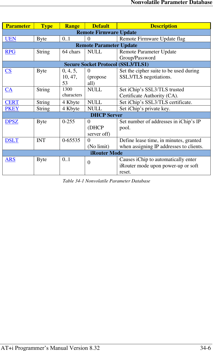
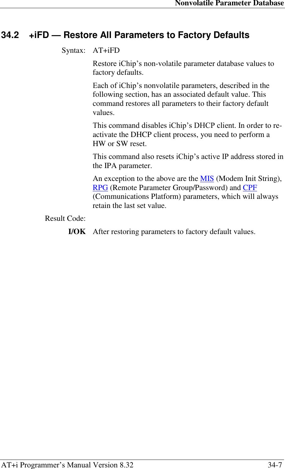
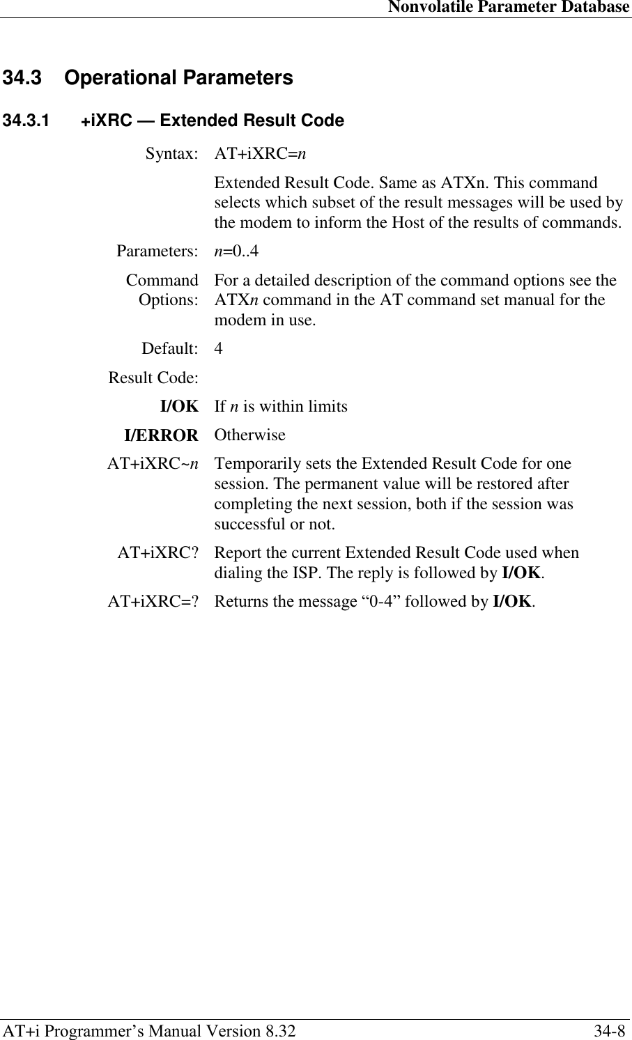
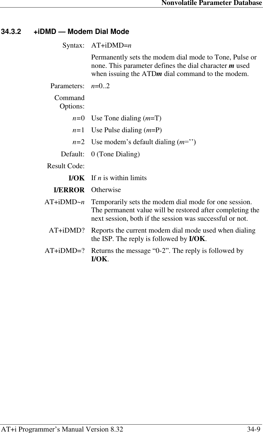
![Nonvolatile Parameter Database AT+i Programmer‘s Manual Version 8.32 34-10 34.3.3 +iMIS — Modem Initialization String Syntax: AT+iMIS=str[;str…] Sets the Modem Initialization String. Parameters: str=Modem initialization string Command Options: str=” Empty: No modem initialization string defined. str=<string> string will be used as the modem initialization string. If string contains special characters, such as quotation marks (‗ or ―), these may be included in string by prefixing each special character with a backslash (‗\‘). For example: ―AT+CGDCONT,\‖IP\‖,\‖INTERNET\‖‖. string must include the AT prefix and the modem reply is expected to include ‗OK‘. MIS may include several consecutive modem commands separated by a semicolon. Each command must begin with ‗AT‘ and its modem reply must include ‗OK‘. iChip will send each ‗AT‘ command separately, followed by <CR> and wait for the ‗OK‘ before proceeding. Default: ‗AT&FE0V1X4Q0&D2M1L3‘ Note: This default value is shipped from the factory. The AT+iFD command does not restore MIS to this value. Result Code: I/OK If str is an empty or a legal string I/ERROR Otherwise AT+iMIS~ str[;str…] Temporarily sets the modem initialization string to str[;str…]. The permanent value will be restored after completing the next session, both if the session was successful or not. AT+iMIS? Reports the current modem initialization string. If the modem initialization string is empty, only <CRLF> will be returned. The reply is followed by I/OK. AT+iMIS=? Returns the message ‗String‘ followed by I/OK.](https://usermanual.wiki/Connect-One/SM2144N1/User-Guide-1162098-Page-173.png)
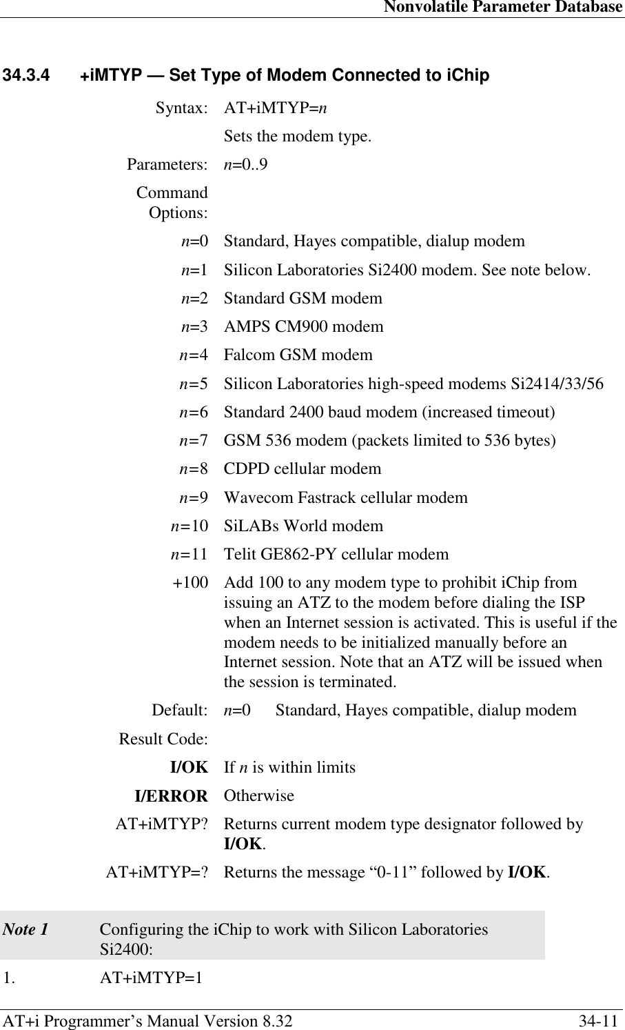
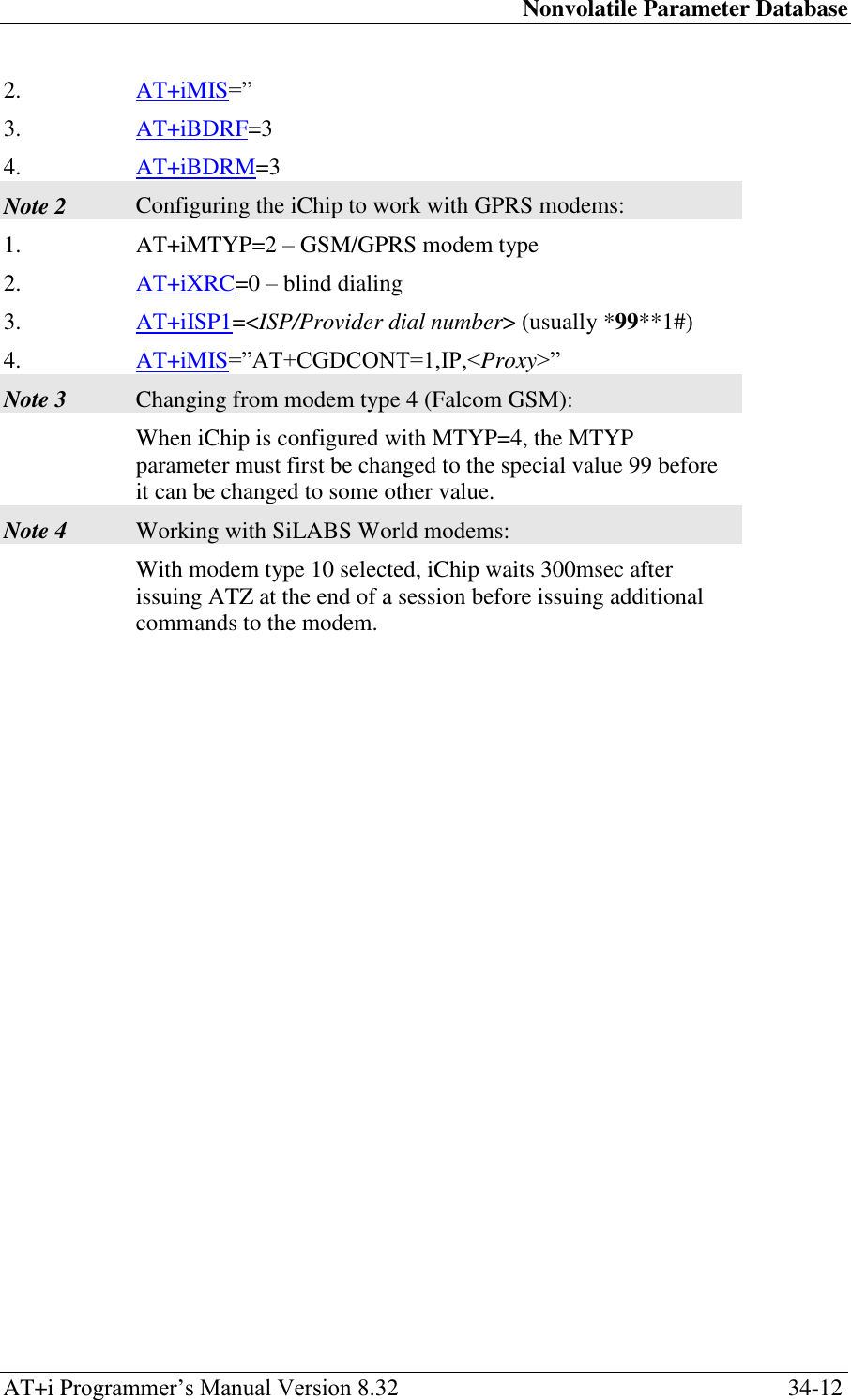
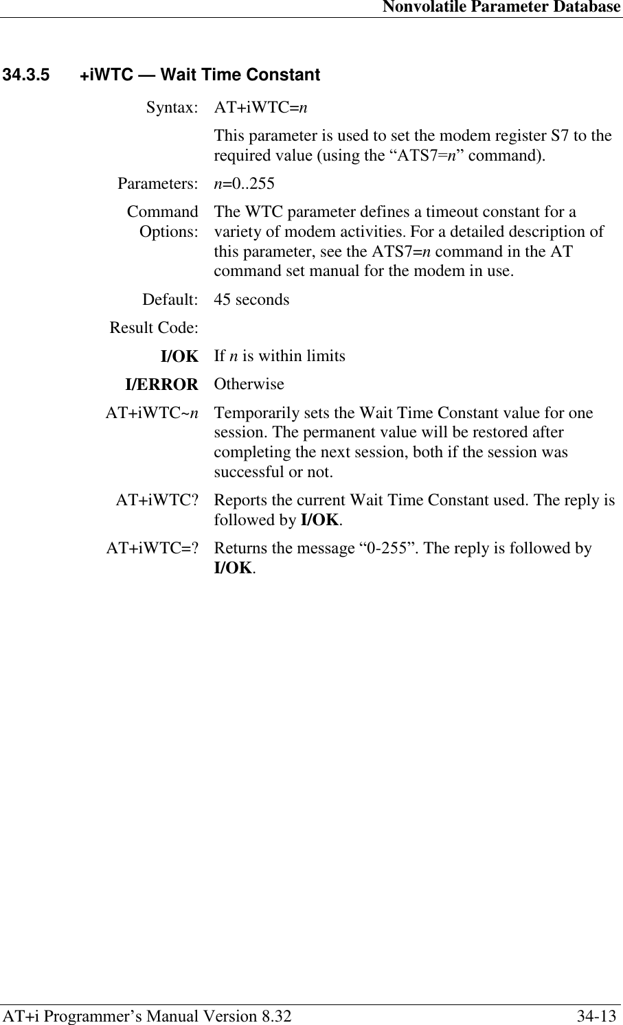
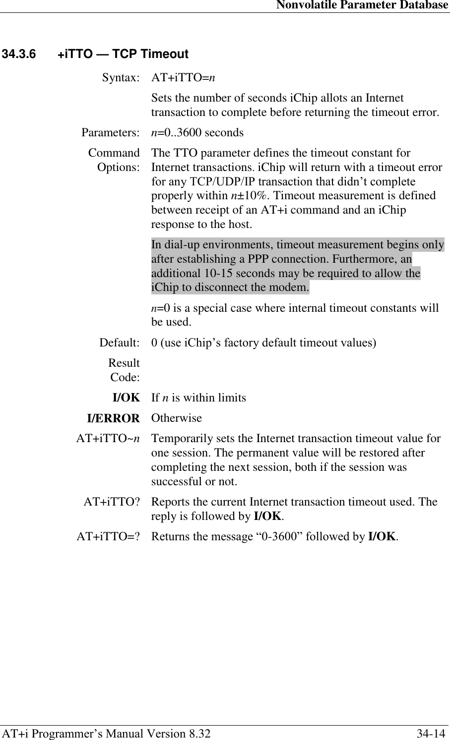
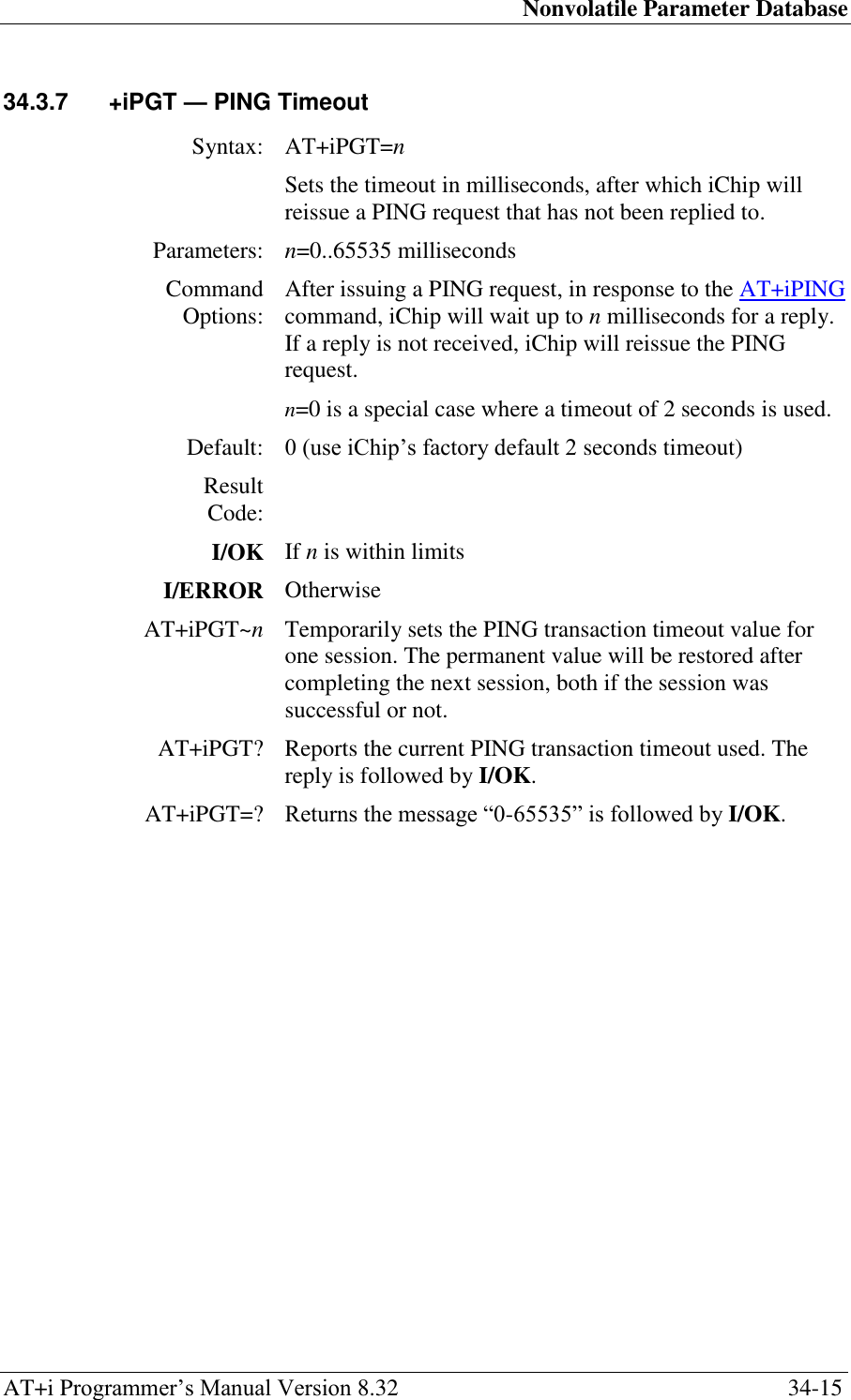
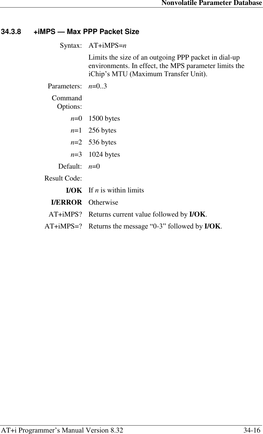
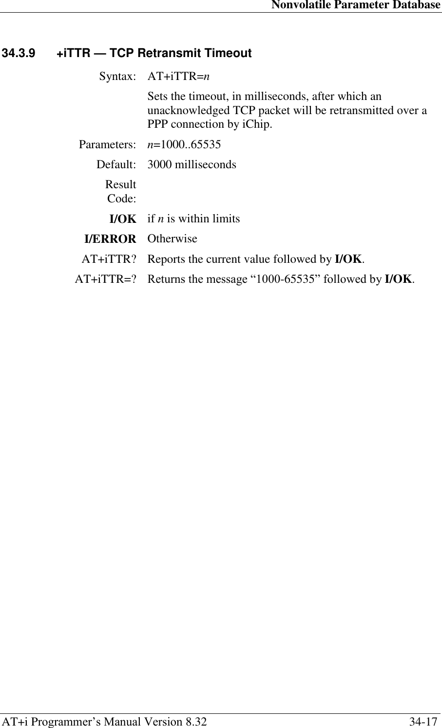
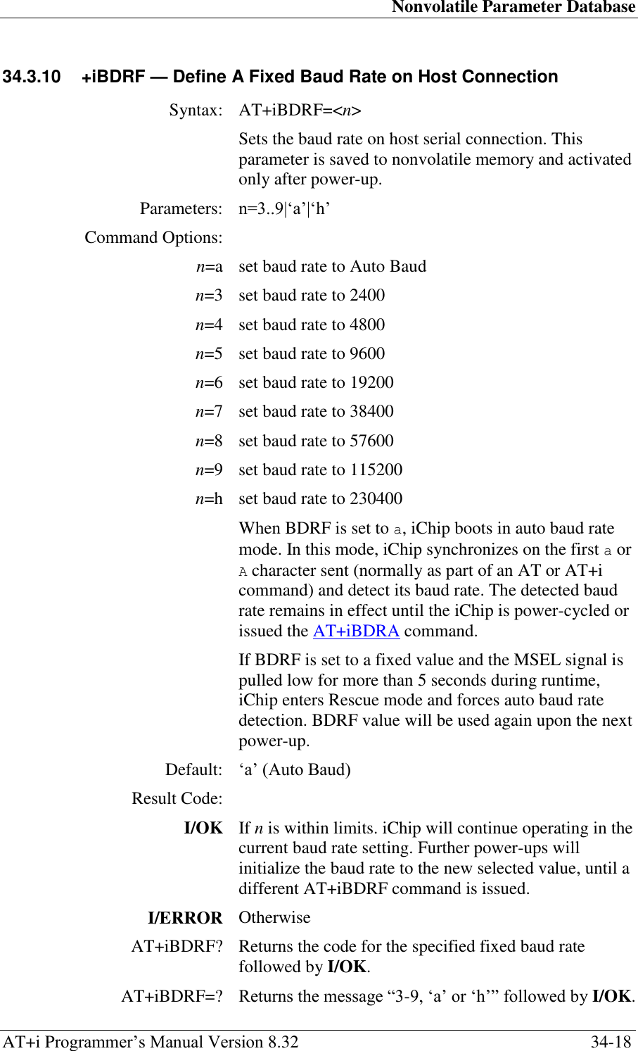
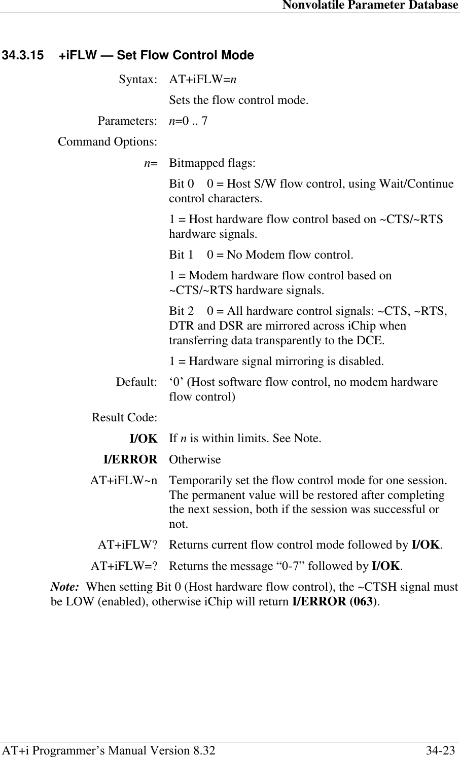
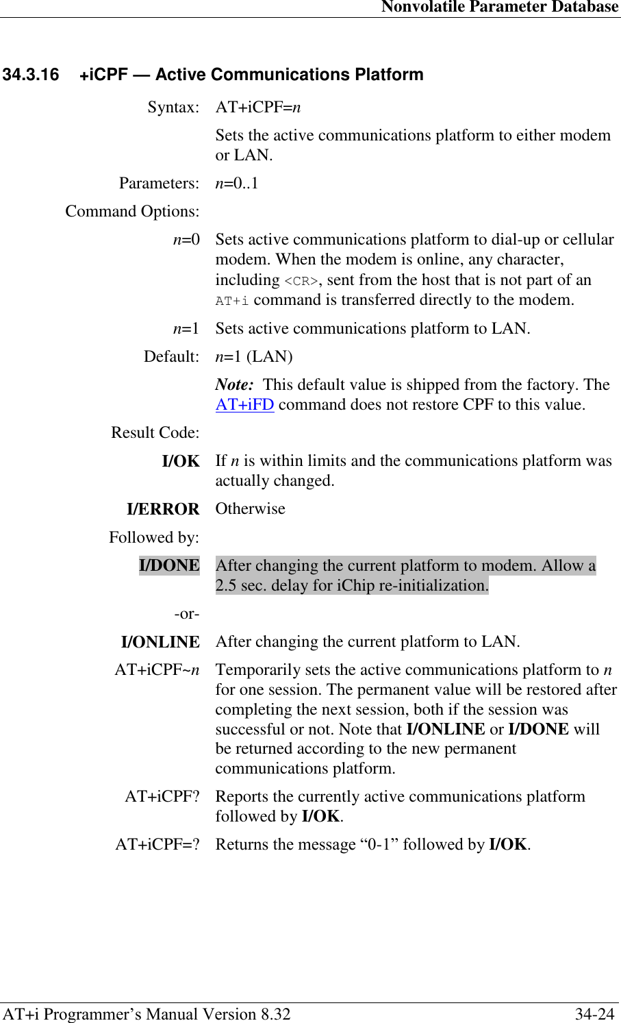
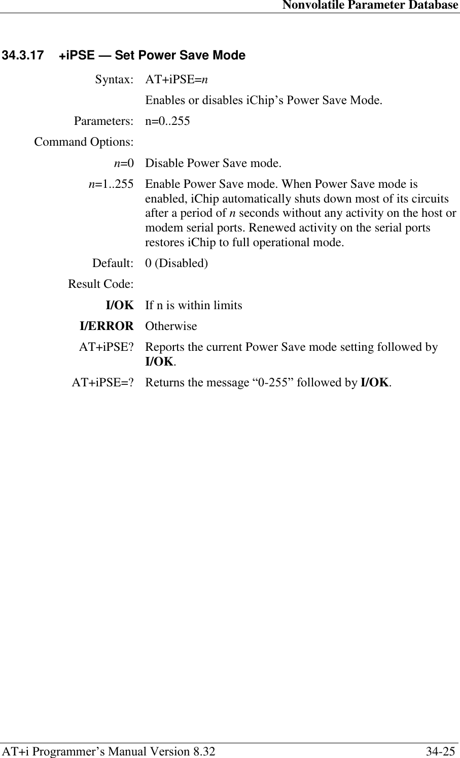
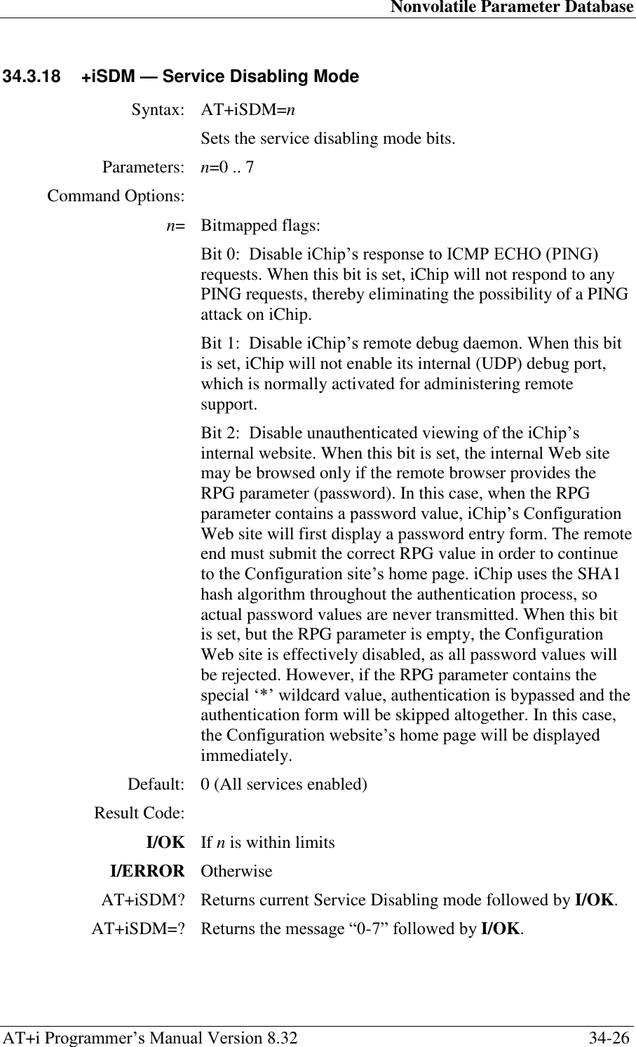
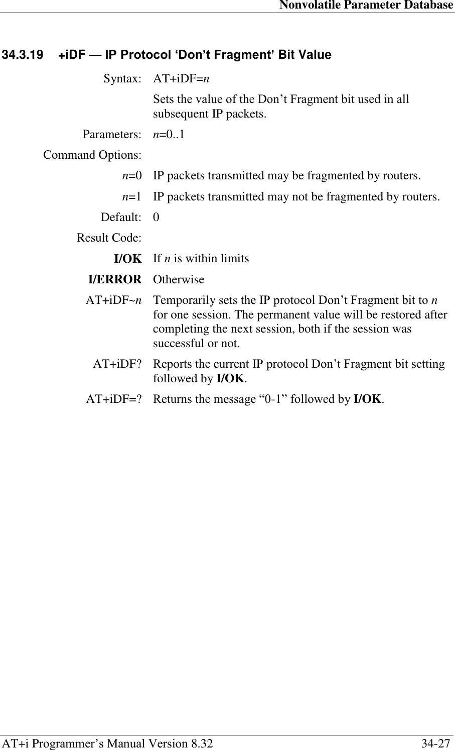
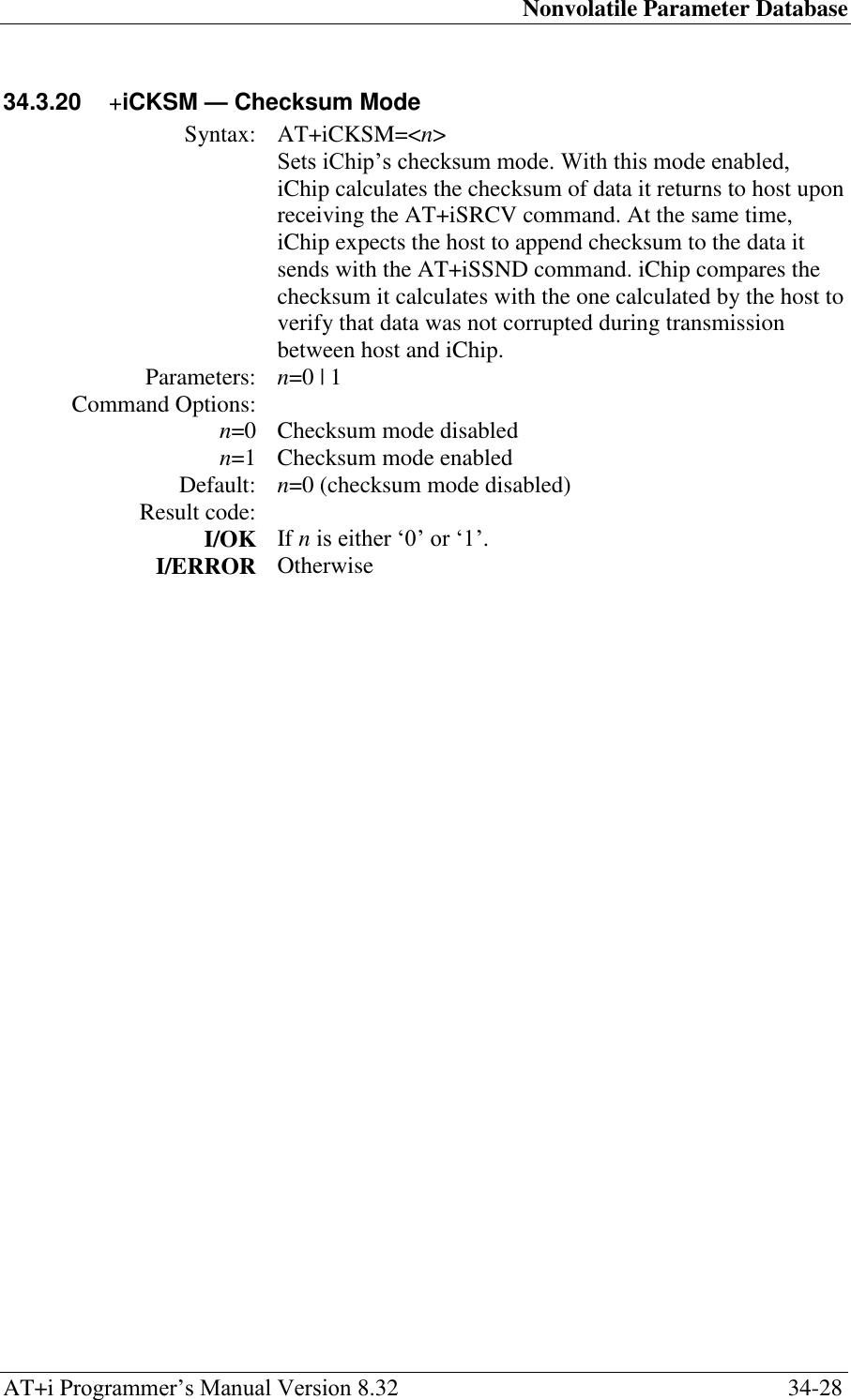
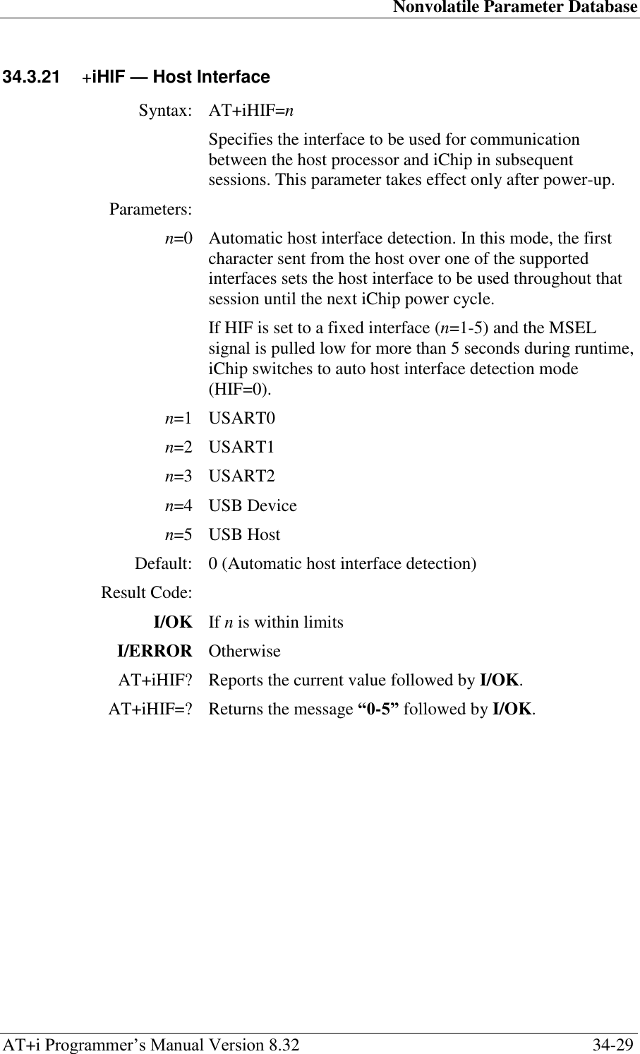
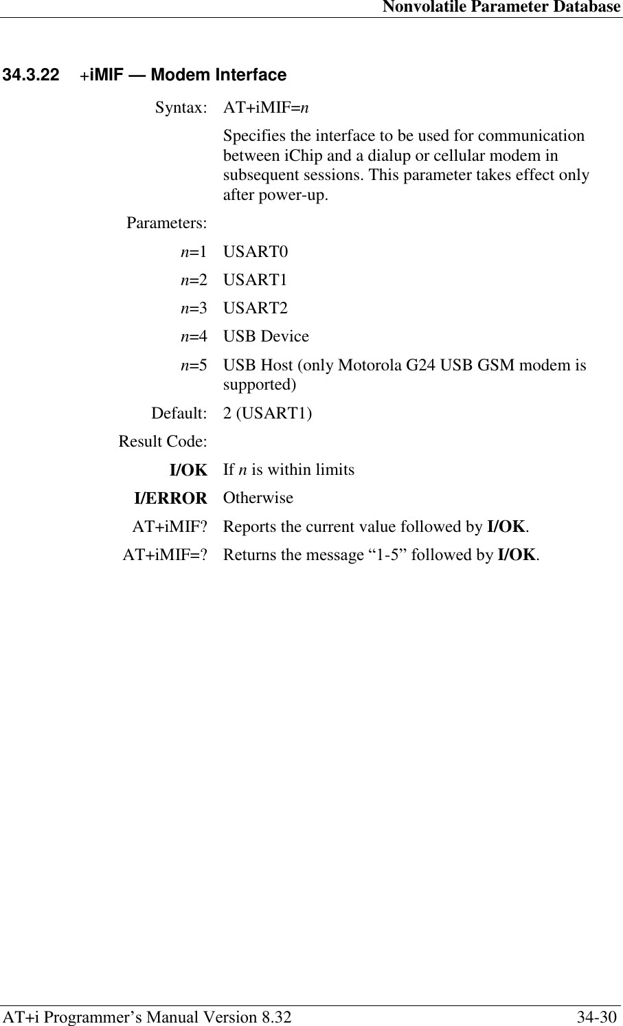
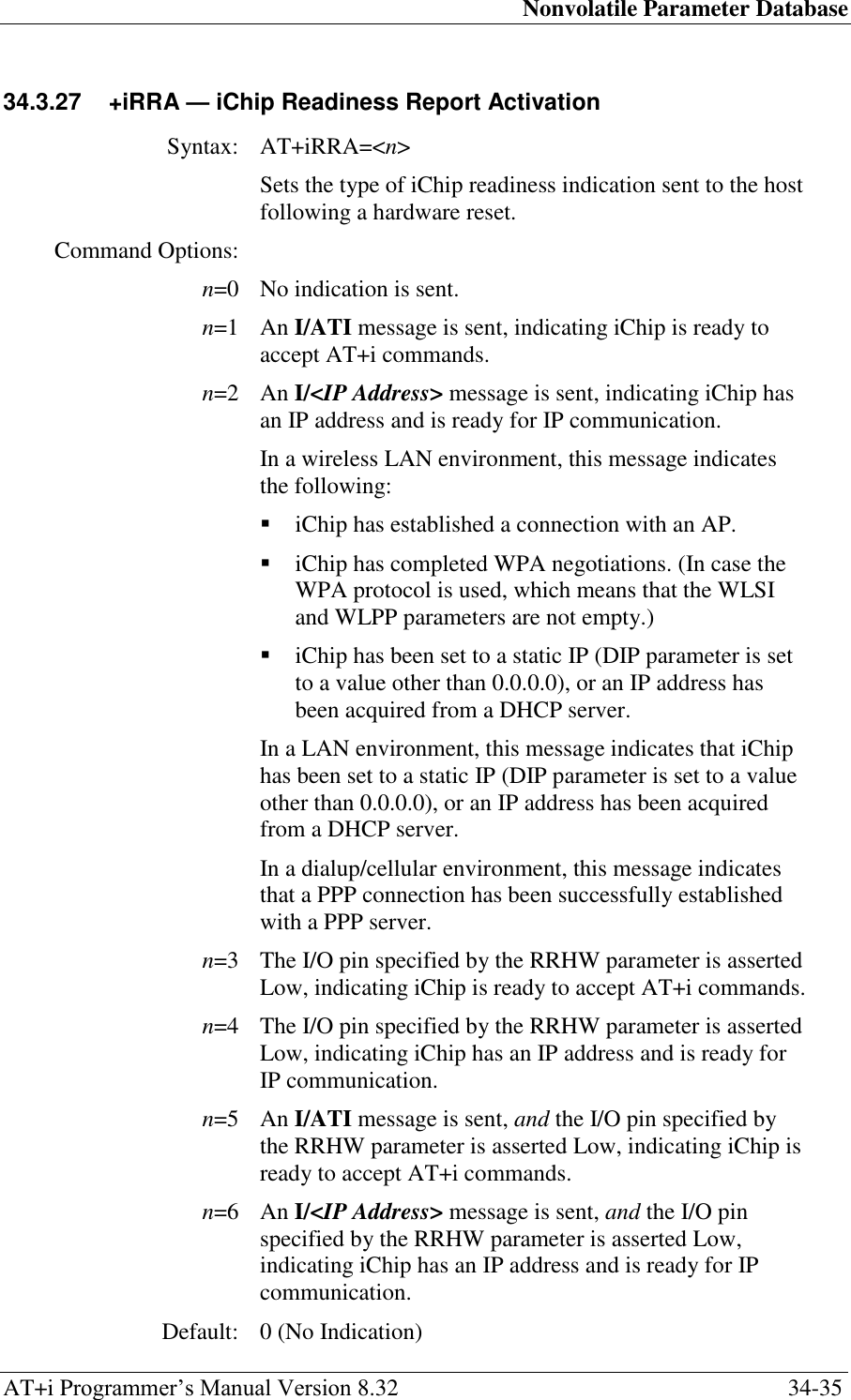
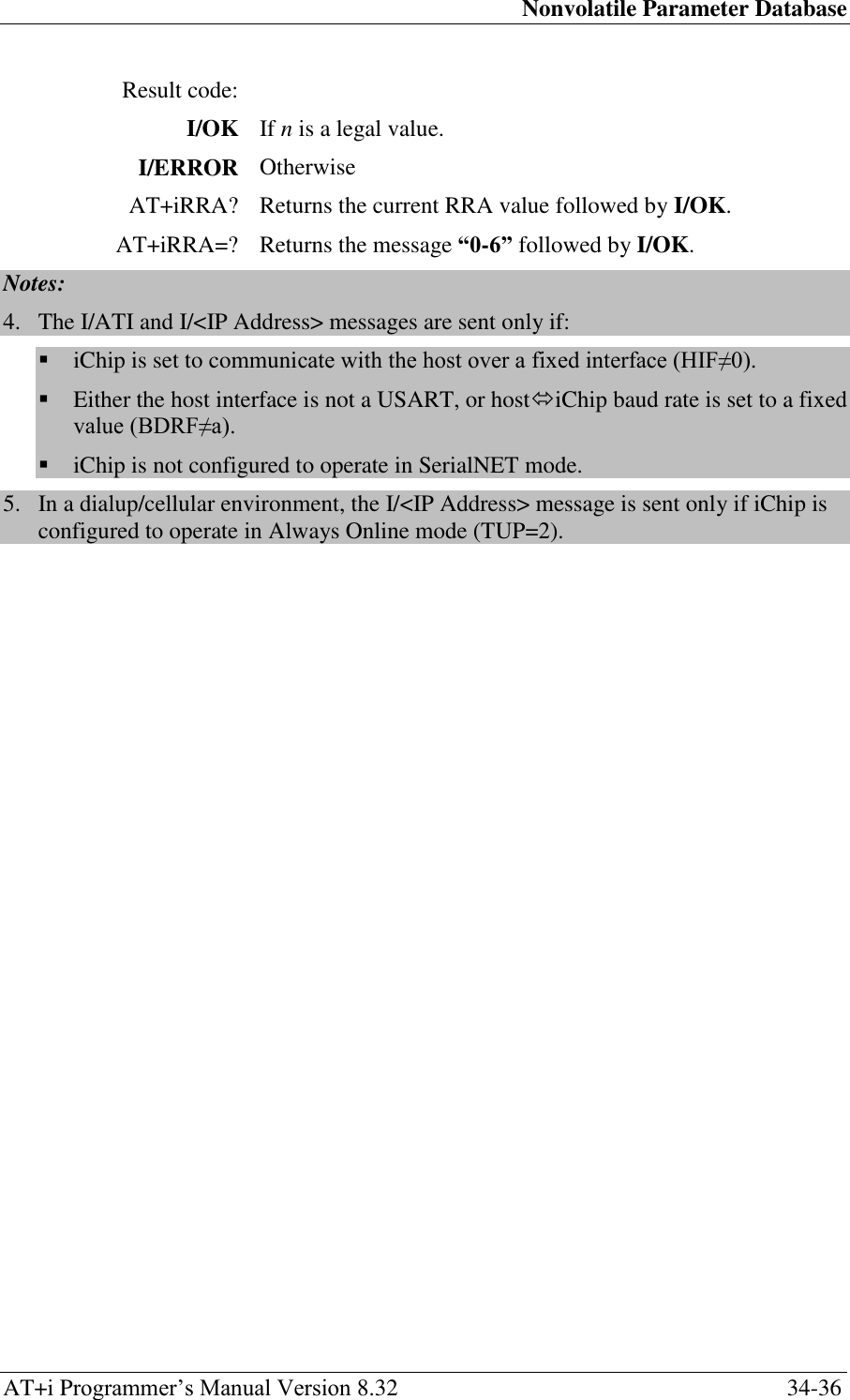
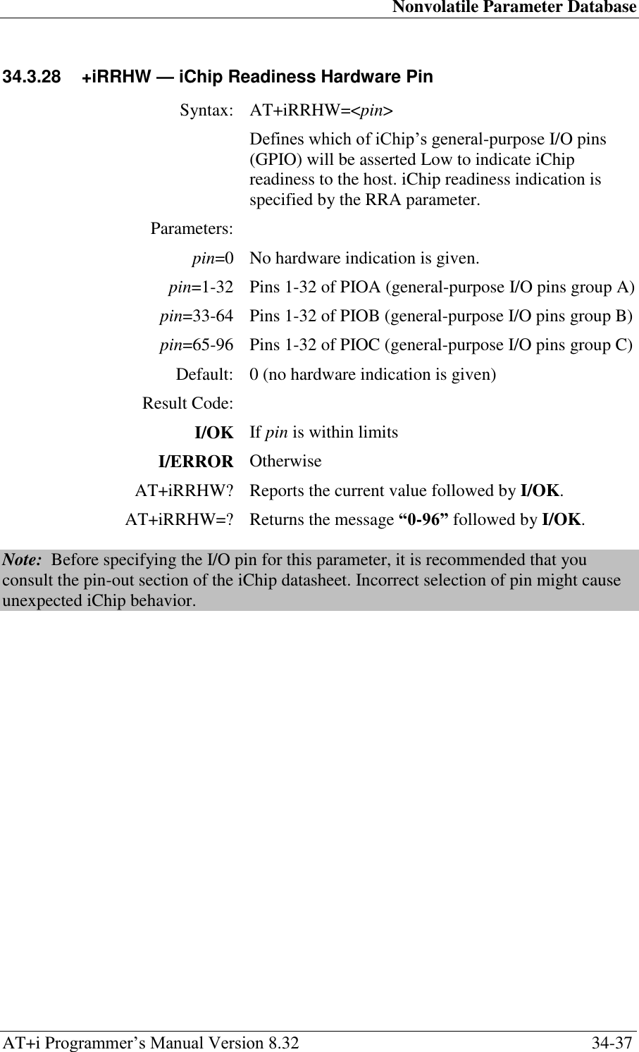
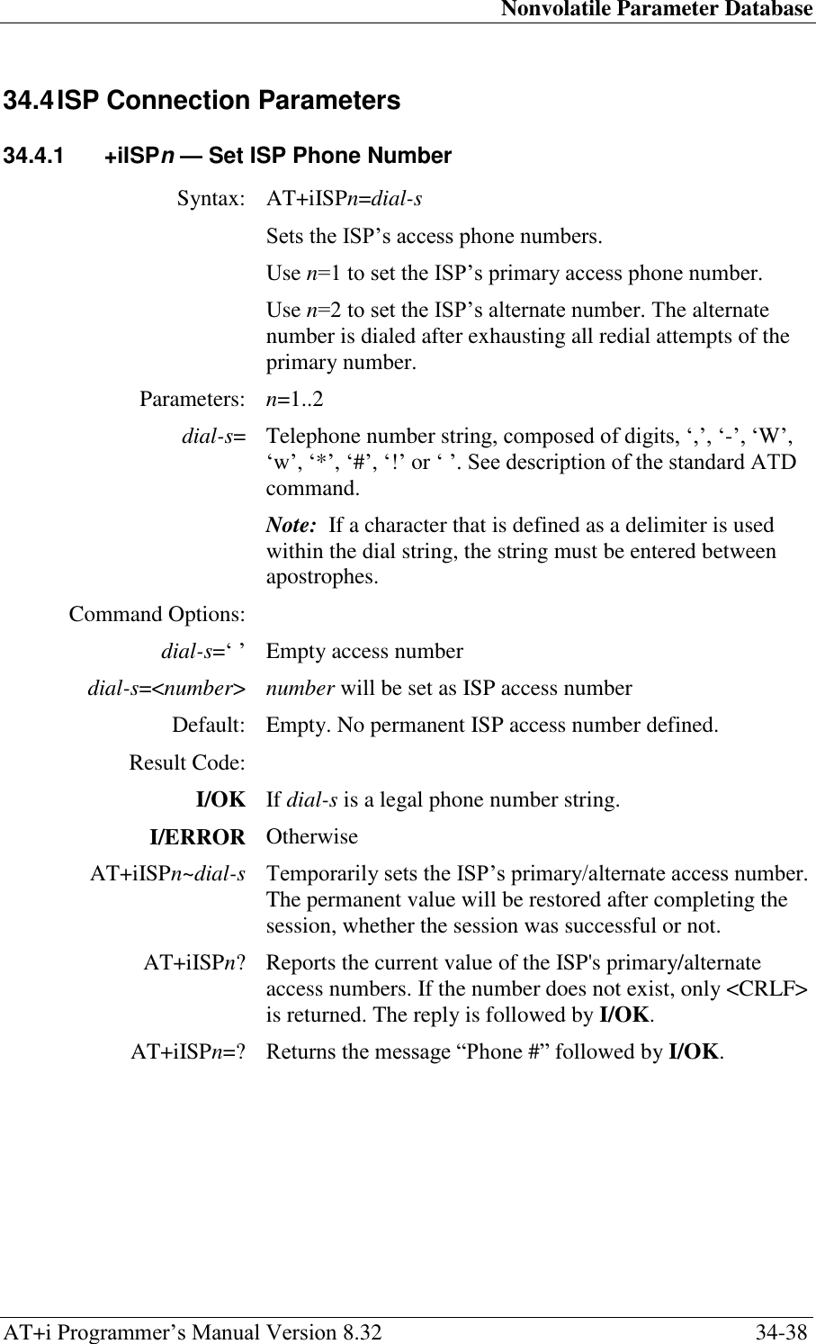
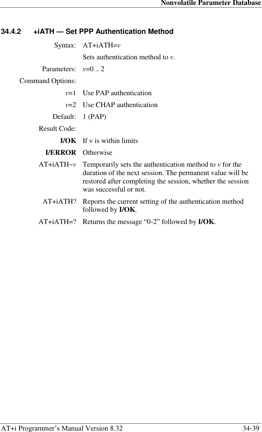
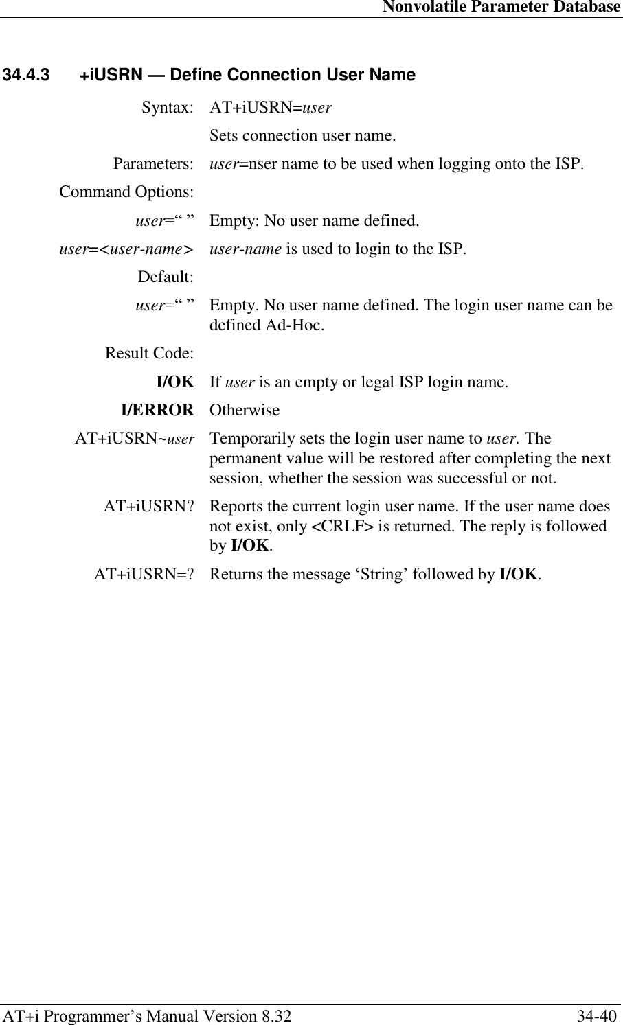
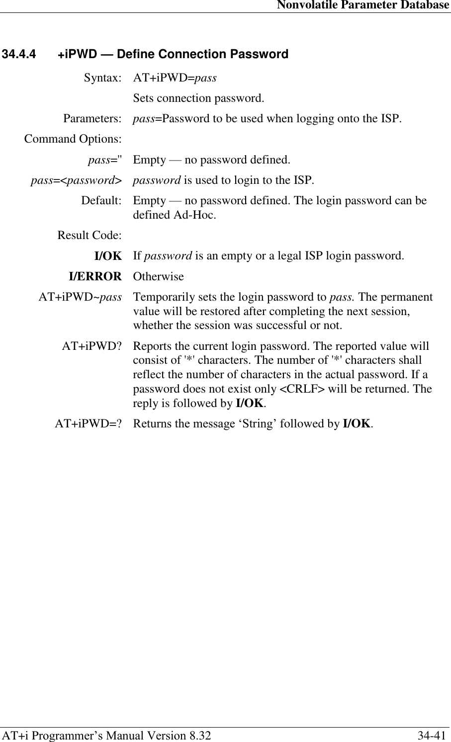
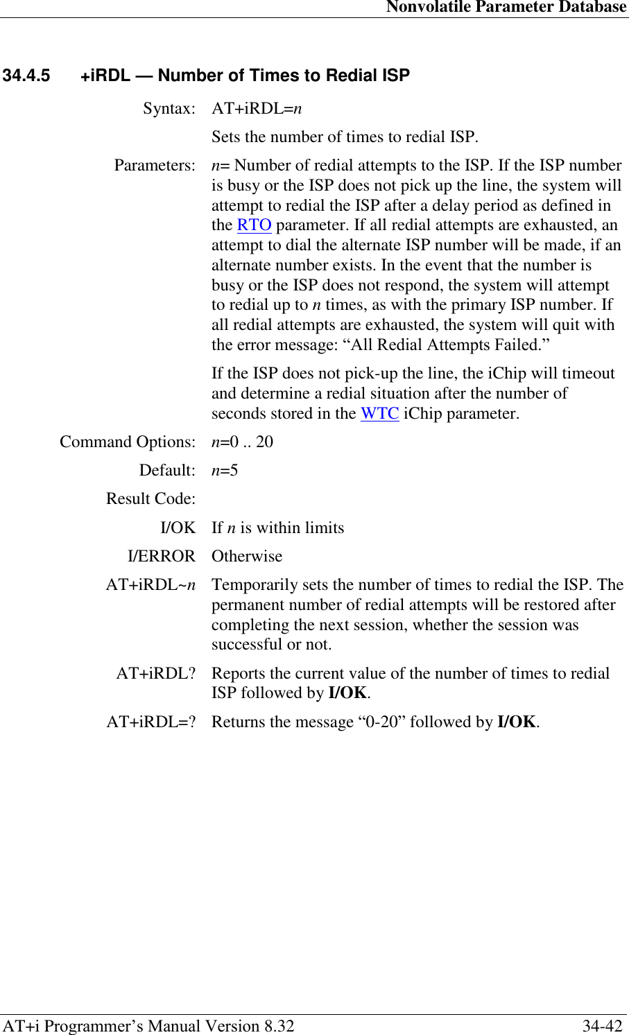
![Nonvolatile Parameter Database AT+i Programmer‘s Manual Version 8.32 34-43 34.4.6 +iRTO — Delay Period between Redials to ISP Syntax: AT+iRTO=n Sets delay period, in seconds, between redials to ISP. Parameters: n= Number of seconds to delay before redialing the ISP, after a busy signal or in the event that the ISP did not answer the call. iChip will enforce a minimal 5 second delay for values of n less than 5 seconds. Command Options: n=0 .. 3600 [seconds] Default: n=180 [seconds] Result Code: I/OK If n is within limits I/ERROR Otherwise AT+iRTO~n Temporarily sets the number of seconds to delay before redialing the ISP. The permanent value will be restored after completing the next session, whether the session was successful or not. AT+iRTO? Reports the current number of seconds to delay before redialing the ISP. The reply is followed by I/OK. AT+iRTO=? Returns the message ―0-3600‖ followed by I/OK.](https://usermanual.wiki/Connect-One/SM2144N1/User-Guide-1162098-Page-206.png)
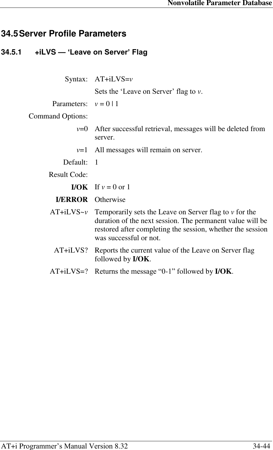
![Nonvolatile Parameter Database AT+i Programmer‘s Manual Version 8.32 34-45 34.5.2 +iDNSn — Define Domain Name Server IP Address Syntax: AT+iDNSn[p]=IP Sets the Domain Name Server IP Address. Use n=1 to define the Primary IP address of the Domain Name Server associated with the ISP. Use n=2 to define the alternate IP address. IP::=<nnn>.<nnn>.<nnn>.<nnn> where, <nnn>: [000..255] Parameters: n=1..2 p= Optional communication platform modifier for iChip Plus. Where, p=‘S‘ to force the (serial) dial-up platform and p=‘L‘ to force the LAN platform. p may be used to select any platform. If p is omitted, the active platform will be used. Command Options: IP=0.0.0.0 Empty: No DNS defined. IP=<IP add> IP add. will be used to communicate to the Domain Name Server on the Internet. Default: Empty. No DNS defined. The DNS must be defined Ad-Hoc. In a LAN environment, an empty DNS (0.0.0.0) will acquire a value from the DHCP server (if DIP is 0.0.0.0). In a dial-up environment, the ISP will assign a DNS IP to an empty DNS, if the ISP supports RFC 1877 (PPP Extensions for Name Server Addresses). Result Code: I/OK If IP is an empty or legal IP address. I/ERROR Otherwise AT+iDNSn[p]~IP Temporarily sets the DNS IP addresses. The permanent values will be restored after completing the next session, whether the session was successful or not. AT+iDNSn[p]? Reports the current main/alternate DNS address. If no DNS address exists, 0.0.0.0 will be returned. The reply is followed by I/OK. AT+iDNSn[p]=? Returns the message ‗IP Addr.‘ followed by I/OK. Note: This parameter may be omitted when the target server is defined with an IP addresses rather than a symbolic name.](https://usermanual.wiki/Connect-One/SM2144N1/User-Guide-1162098-Page-208.png)
![Nonvolatile Parameter Database AT+i Programmer‘s Manual Version 8.32 34-46 34.5.3 +iSMTP — Define SMTP Server Name Syntax: AT+iSMTP[p]=server Permanently sets the SMTP Server Name or IP. Parameters: server = An SMTP server name or IP address. Server names must be resolvable by the primary or alternate DNS. p = optional communication platform modifier for iChip Plus. Where, p=‘S‘ to force the (serial) dial-up platform and p=‘L‘ to force the LAN platform. p may be used to select any platform. If p is omitted, the active platform will be used. Command Options: server = '' Empty: No server name defined. server = <SMTP_SRVR> SMTP_SRVR will be used to locate and establish an SMTP connection when sending Email messages. If SMTP_SRVR is a symbolic name, a DNS server will be used to resolve the IP address. Define +iSMA, +iSMU and +iSMP if the SMTP server requires authentication. Default: Empty. No SMTP server defined. To send Email messages, the SMTP server name must be defined Ad-Hoc. In a LAN environment, an empty SMTP server will acquire a value from the DHCP server (if DIP is 0.0.0.0). Result code: I/OK If server is an empty or legal IP address or SMTP server name. I/ERROR Otherwise. AT+iSMTP[p]~ server Temporarily set the SMTP server name to server. The permanent server name will be restored after completing the next session, whether the session was successful or not. AT+iSMTP[p]? Report the current SMTP server name. If a server name does not exist, only <CRLF> will be returned. The reply is followed by I/OK. AT+iSMTP[p]=? Returns the message ‗String/IP‘. The reply is followed by I/OK.](https://usermanual.wiki/Connect-One/SM2144N1/User-Guide-1162098-Page-209.png)
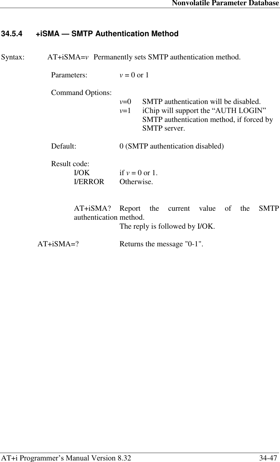
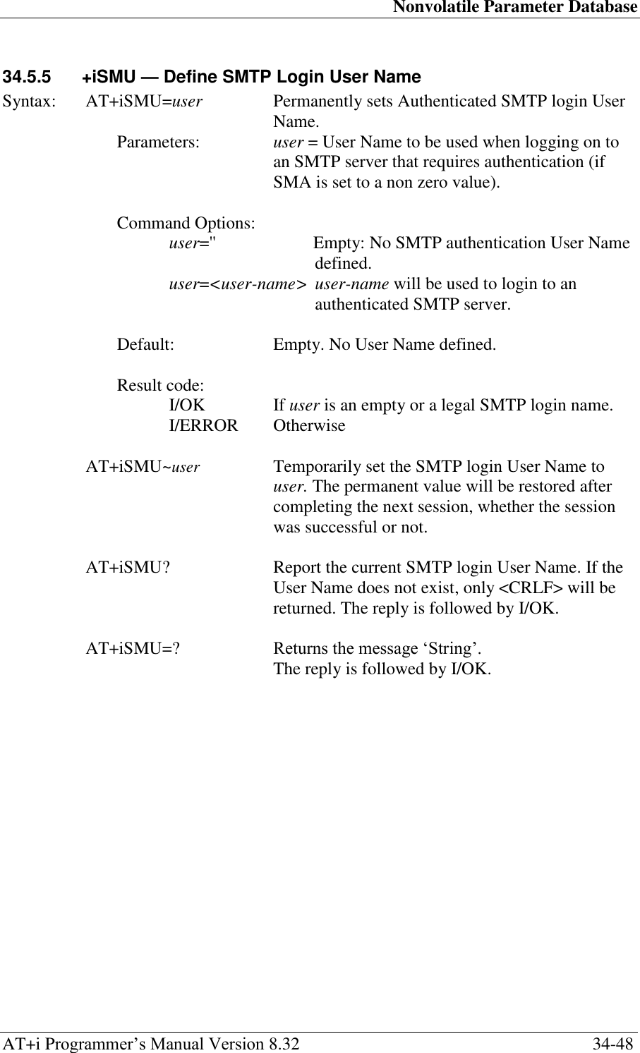
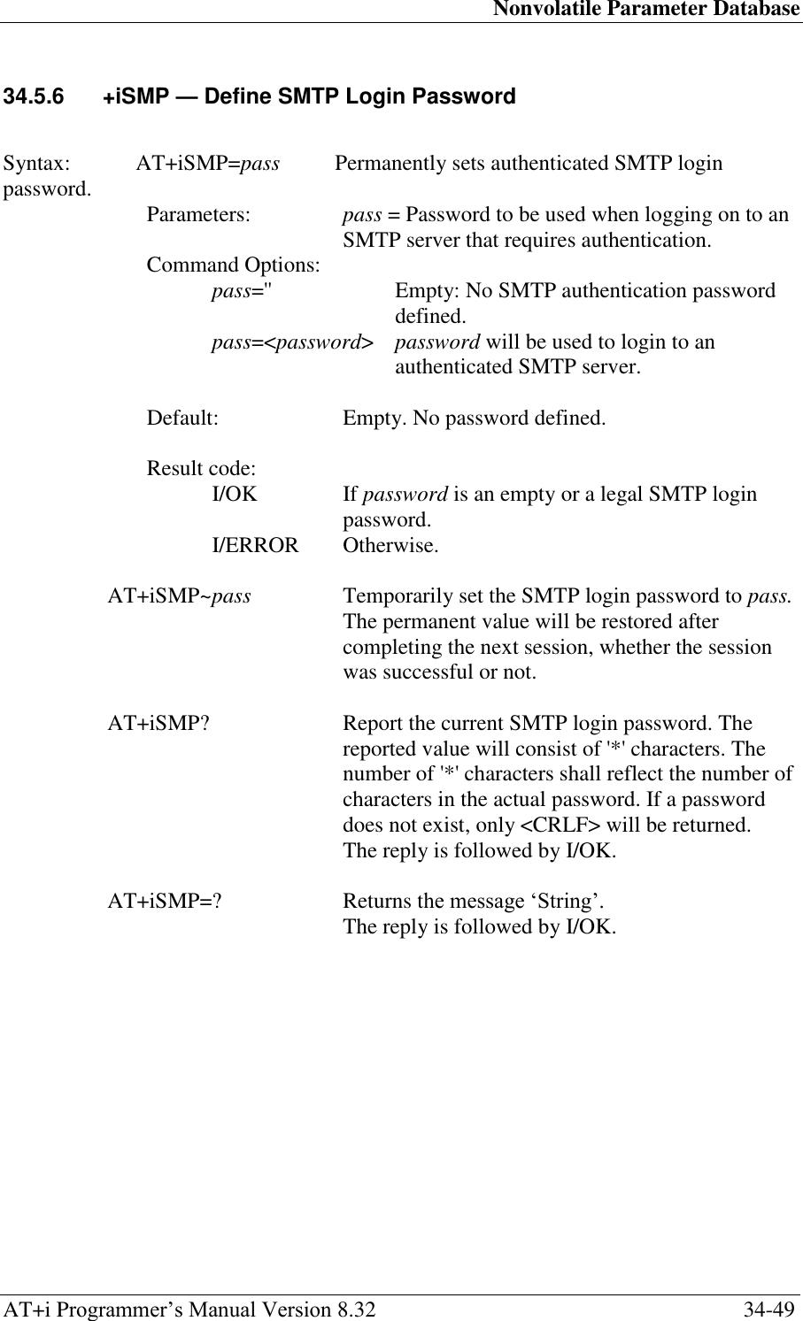
![Nonvolatile Parameter Database AT+i Programmer‘s Manual Version 8.32 34-50 34.5.7 +iPOP3 — Define POP3 Server Name Syntax: AT+iPOP3[p]=server Permanently sets the POP3 Server Name or IP. Parameters: server = a POP3 Server Name or IP address. The Server Name must be resolvable by the primary or alternate DNS. p = optional communication platform modifier for iChip Plus. Where, p=‘S‘ to force the (serial) dial-up platform and p=‘L‘ to force the LAN platform. p may be used to select any platform. If p is omitted, the active platform will be used. Command Options: server = '' Empty: No Server Name defined. server = <POP3_SRVR> POP3_SRVR will be used to locate and establish a POP3 connection when recieving Email messages. If POP3_SRVR is a symbolic name, a DNS server will be used to resolve the IP address. Default: Empty. No POP3 server defined. To retrieve Email messages, a POP3 Server Name must be defined Ad-Hoc. In a LAN environment, an empty POP3 server will acquire a value from the DHCP server (if DIP is 0.0.0.0). Result code: I/OK If server is empty or a legal IP address or POP3 server name. I/ERROR Otherwise AT+iPOP3[p]~ server Temporarily set the POP3 server name to server. The permanent server name will be restored after completing the next session, whether the session was successful or not. AT+iPOP3[p]? Report the current POP3 server name. If a server name does not exist, only <CRLF> will be returned. The reply is followed by I/OK. AT+iPOP3[p]=? Returns the message ‗String/IP‘. The reply is followed by I/OK.](https://usermanual.wiki/Connect-One/SM2144N1/User-Guide-1162098-Page-213.png)
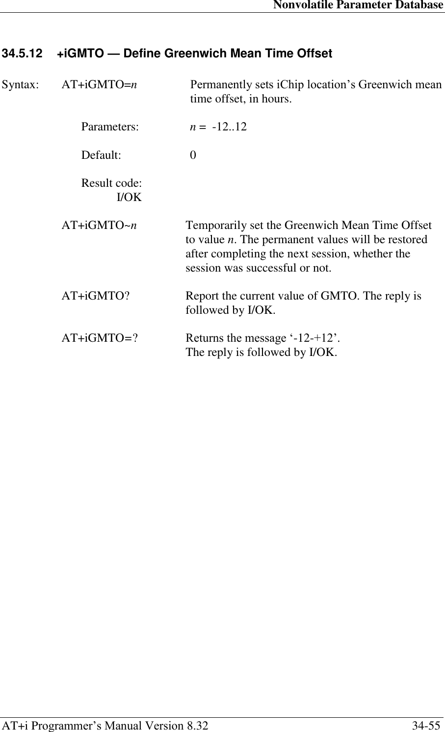
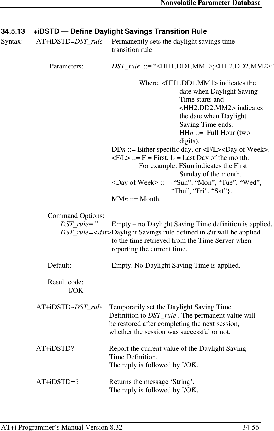
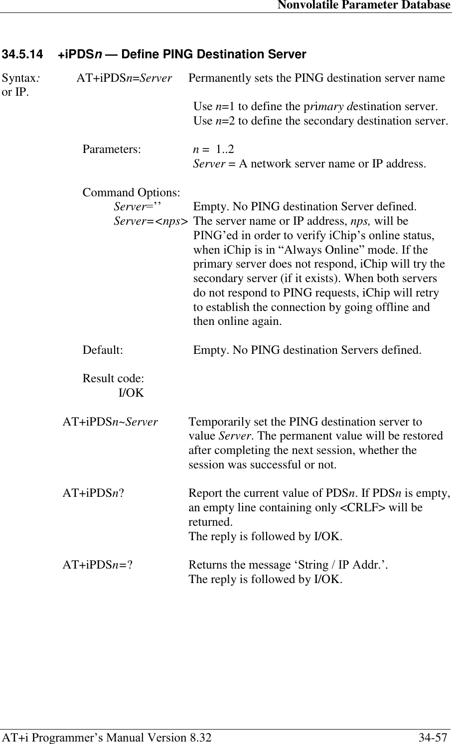
![Nonvolatile Parameter Database AT+i Programmer‘s Manual Version 8.32 34-58 34.5.15 +iPFR — PING Destination Server Polling Frequency Syntax: AT+iPFR=n Permanently sets the time interval, in seconds, upon which iChip will issue a PING request to one of the PING destination servers. Parameters: n = 0..65535 [seconds] Command Options: Default: 0 (Disabled PING polling) Result code: I/OK If n is within limits I/ERROR Otherwise AT+iPFR~n Temporarily set the PING polling interval value for one session. The permanent value will be restored after completing the next session, whether the session was successful or not. AT+iPFR? Report the current PING polling interval used. The reply is followed by I/OK. AT+iPFR=? Returns the message "0-65535". The reply is followed by I/OK.](https://usermanual.wiki/Connect-One/SM2144N1/User-Guide-1162098-Page-221.png)
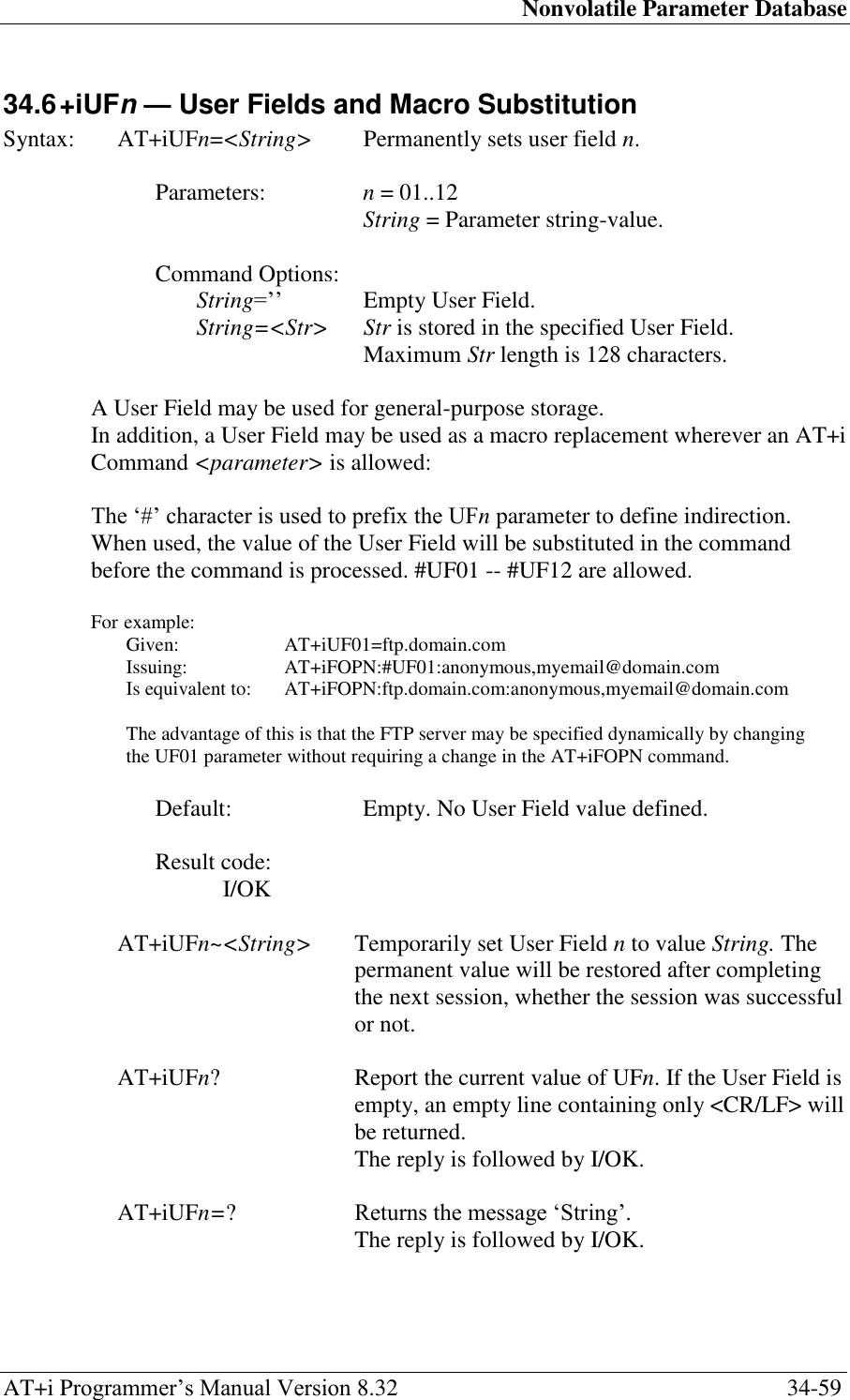
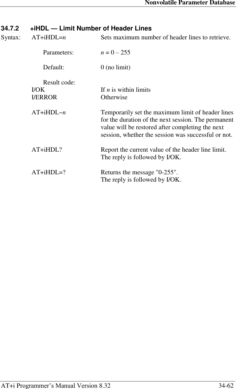
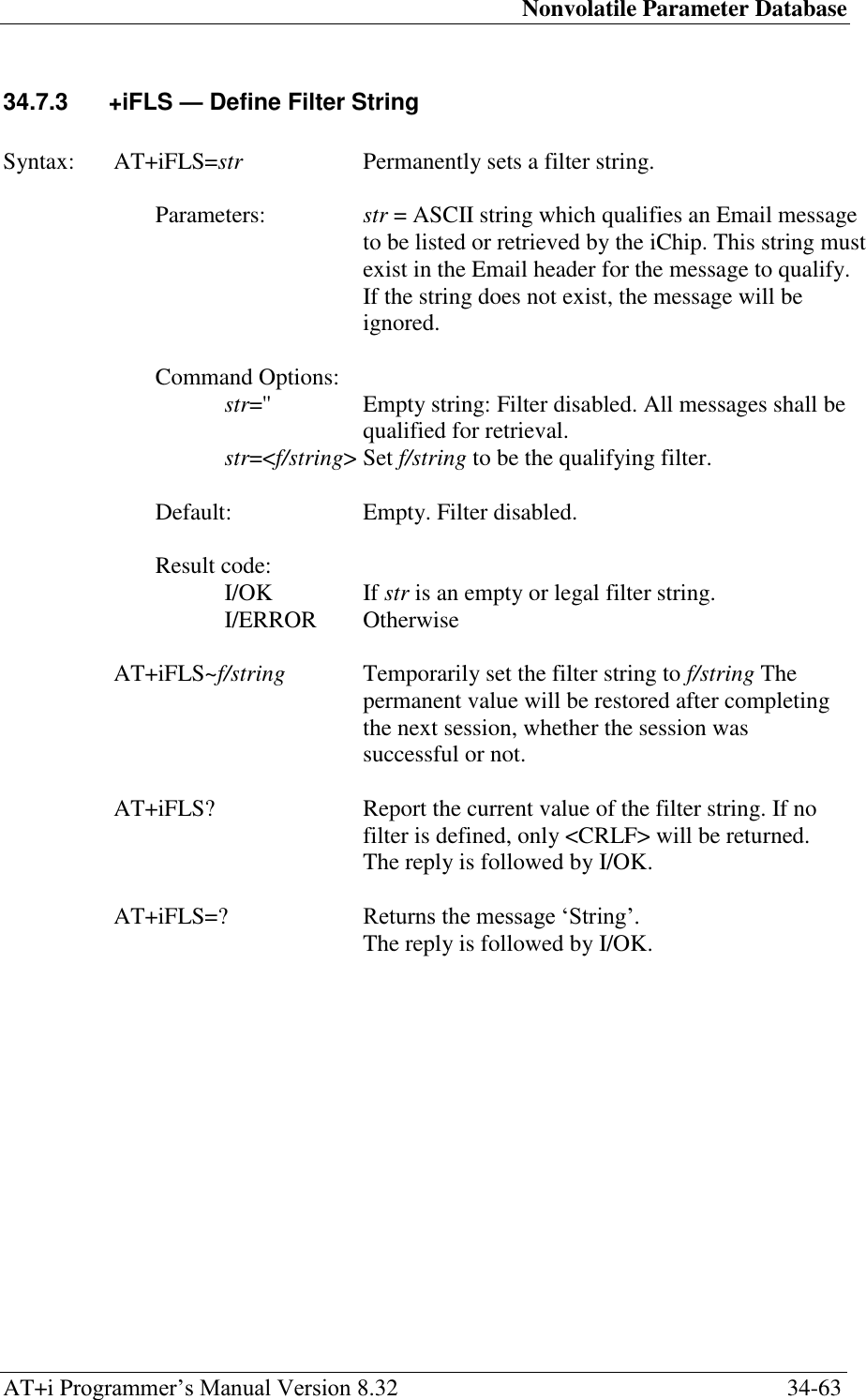
![Nonvolatile Parameter Database AT+i Programmer‘s Manual Version 8.32 34-64 34.7.4 +iDELF — Email Delete Filter String Syntax: AT+iDELF=[#]str Permanently sets the Email delete filter string. Parameters: str = ASCII string which qualifies an Email message to be deleted from the mailbox. This string must exist in the Email header for the message to qualify. If the string exists in at least one header field, the message will be deleted from the mailbox during the next Email retrieve session (AT+iRMM). Command Options: str='' Empty string: delete filter disabled. No messages shall be deleted. str=<f/string> Set f/string to be the qualifying Email delete filter. # flag When the optional ‗#‘ (NOT) flag precedes the filter string, iChip will reverse the deletion criterion. In other words, iChip will delete all but Emails that qualify the filter. Default: Empty. Delete filter disabled. Result code: I/OK If str is an empty or legal filter string. I/ERROR Otherwise. AT+iDELF~[#]f/string Temporarily set the Email delete filter string to f/string. The permanent value will be restored after completing the next session, whether the session was successful or not. AT+iDELF? Report the current value of the Email delete filter string. If no filter is defined, only <CRLF> will be returned. The reply is followed by I/OK. AT+iDELF=? Returns the message ‗String‘. The reply is followed by I/OK.](https://usermanual.wiki/Connect-One/SM2144N1/User-Guide-1162098-Page-227.png)
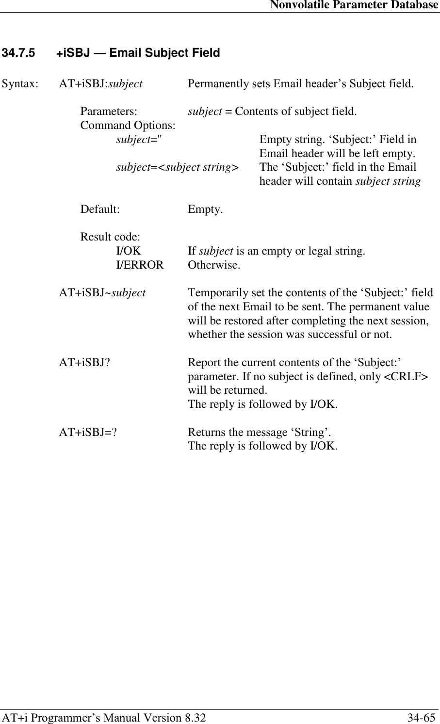
![Nonvolatile Parameter Database AT+i Programmer‘s Manual Version 8.32 34-66 34.7.6 +iTOA — Define Primary Addressee Syntax: AT+iTOA[n]=Email@ Permanently sets Email addressee. Parameters: Email@ = Email addressee. This is the default Email addressee, which will be used to direct Email messages sent by iChip. n = optional index of addressee. When n is not specified, TOA00 (primary addressee) is used. Command Options: Email@='' Empty address: No addressee defined. Email@=<addr> addr will be used as a destination address for future Email SEND commands (+iEMA, +iEMB). n = 01..50 Default: Empty. No addressee defined. Result code: I/OK AT+iTOA[n]~<add> Temporarily set the Email addressee to add. The permanent value will be restored after completing the next session, whether the session was successful or not. AT+iTOA[n]? Report the current value of the Email addressee. If the addressee does not exist, an empty line containing only <CRLF> will be returned. The reply is followed by I/OK. AT+iTOA[n]=? Returns the message ‗String‘. The reply is followed by I/OK.](https://usermanual.wiki/Connect-One/SM2144N1/User-Guide-1162098-Page-229.png)
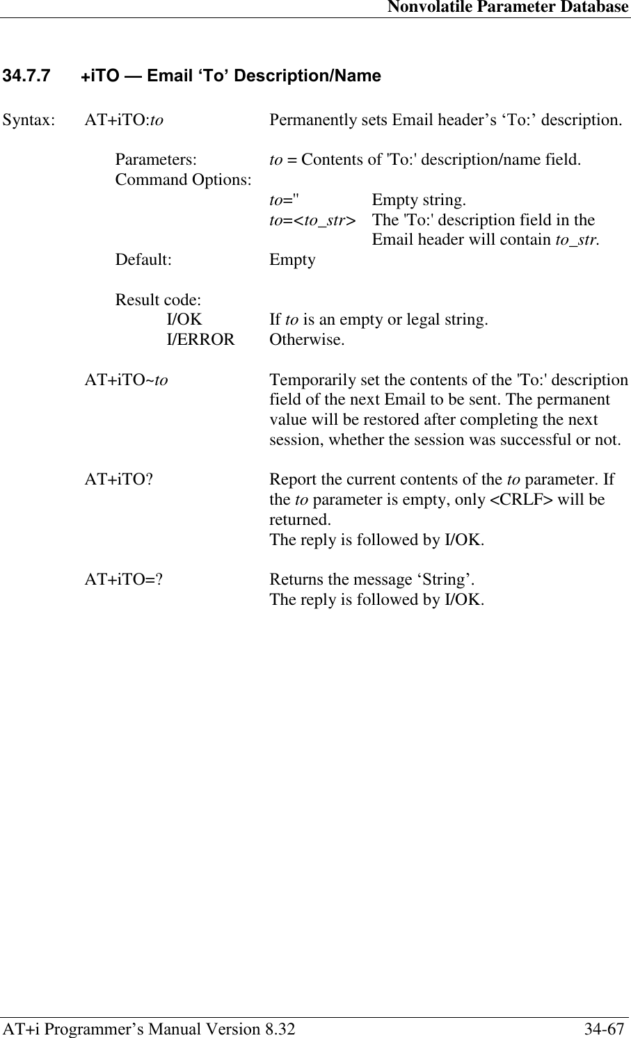
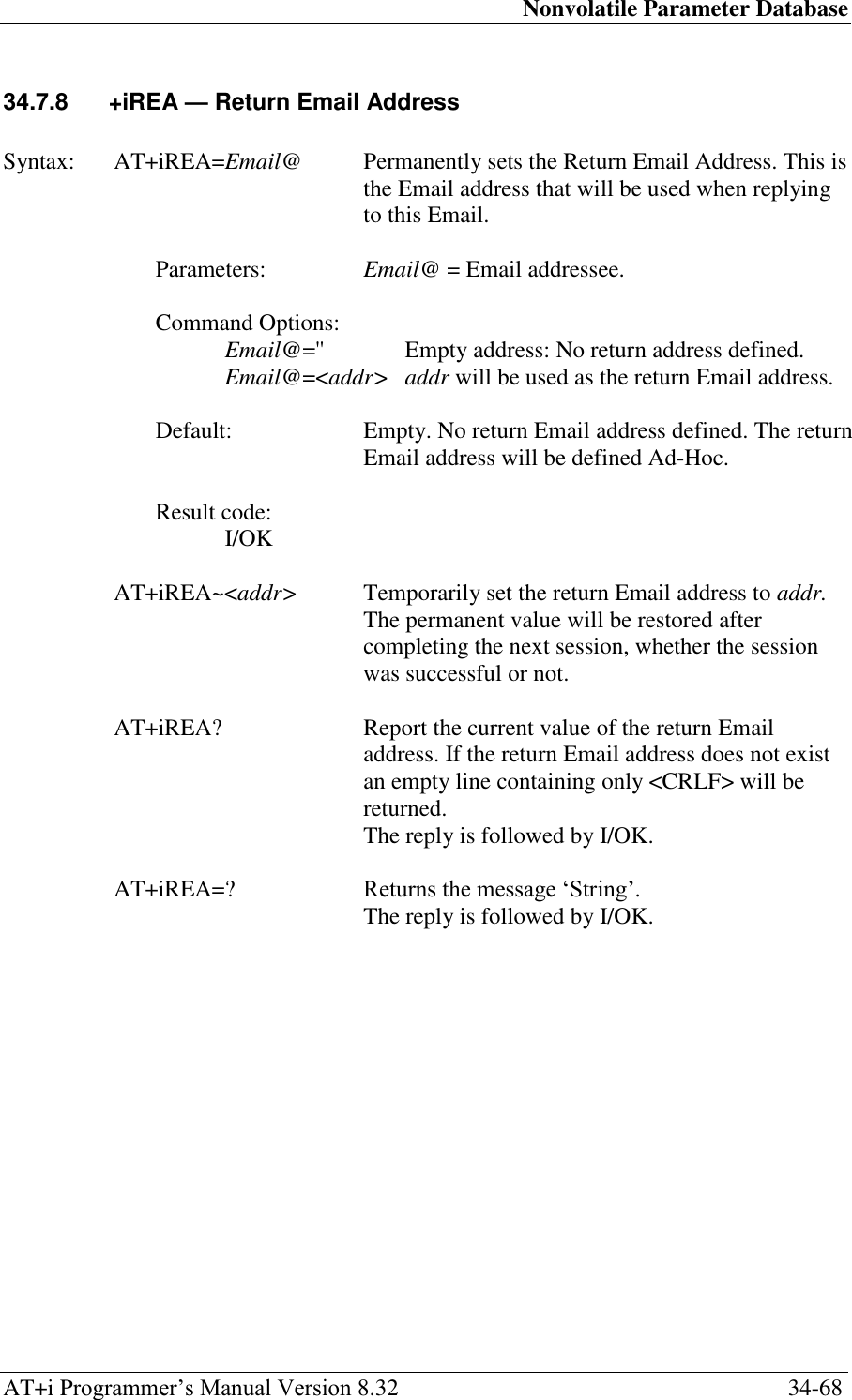
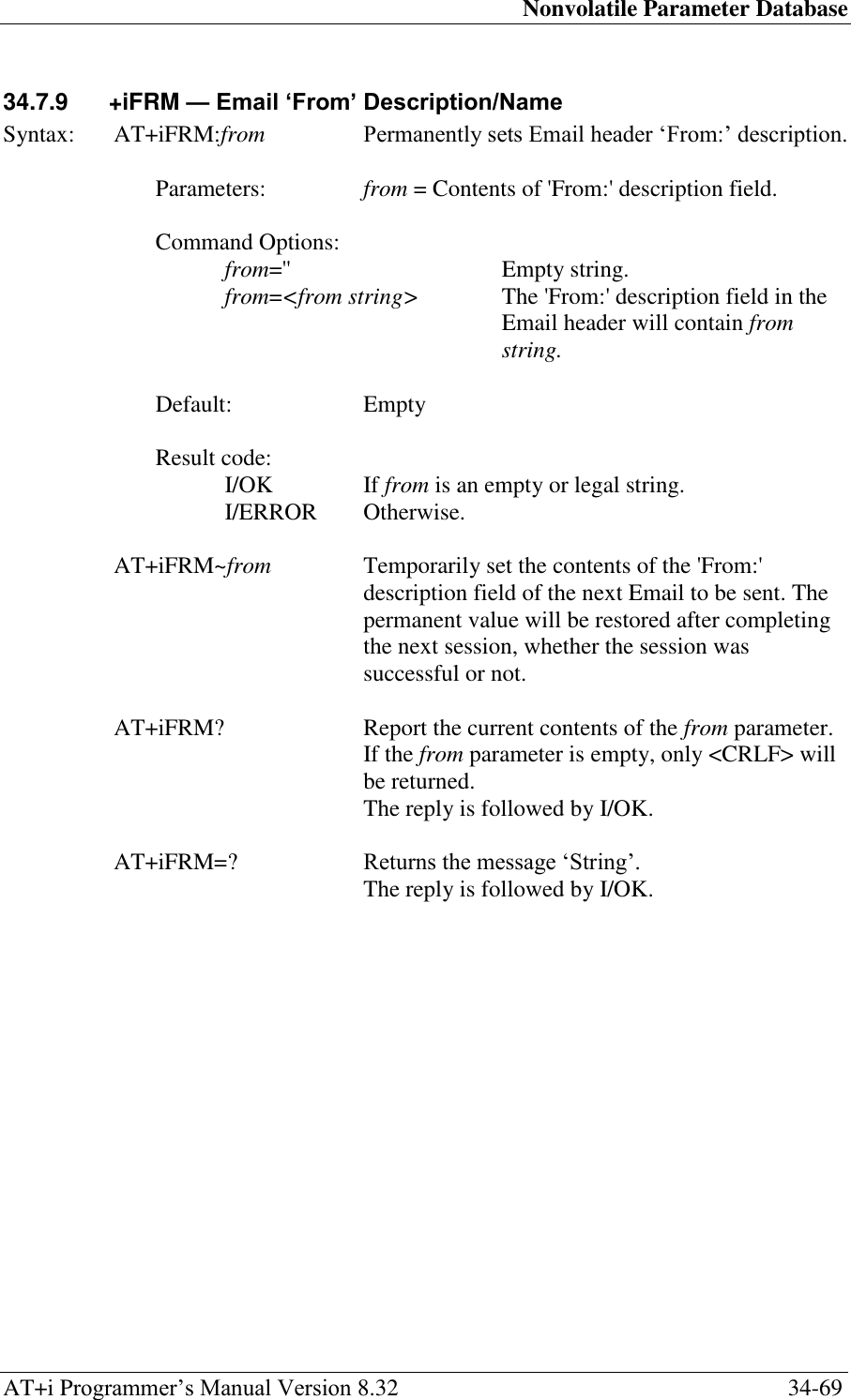
![Nonvolatile Parameter Database AT+i Programmer‘s Manual Version 8.32 34-75 34.8.1 +iURL — Default URL Address Syntax: AT+iURL=URLadd Sets the URL address string used for downloading web pages and files and uploading files to web servers. Parameters: URLadd = URL address string. Command Options: URLadd ='' Empty: No URL address string defined. URLadd =<str> str will be used as the URL address string when downloading a Web page or file. The URL address format is: <Protocol>://<host>[[:<port>]/[<absolute_link>]/] Where, <protocol> -- HTTP or HTTPS <host> -- Web Server Name: IP address or server name resolved by DNS. <port> -- Port number on server. Default: 80 for HTTP, 443 for HTTPS. <absolute link> -- Absolute path name of Web page or file on server. Default: None Result code: I/OK If URLadd is an empty or a legal URL address string. I/ERROR Otherwise AT+iURL~URLadd Temporarily set the URL address string to URLadd. The permanent value will be restored after completing the next session, whether the session was successful or not. AT+iURL? Report the current URL address string. If the URL address is empty, only <CRLF> will be returned. The reply is followed by I/OK. AT+iURL=? Returns the message ‗String‘. The reply is followed by I/OK.](https://usermanual.wiki/Connect-One/SM2144N1/User-Guide-1162098-Page-238.png)
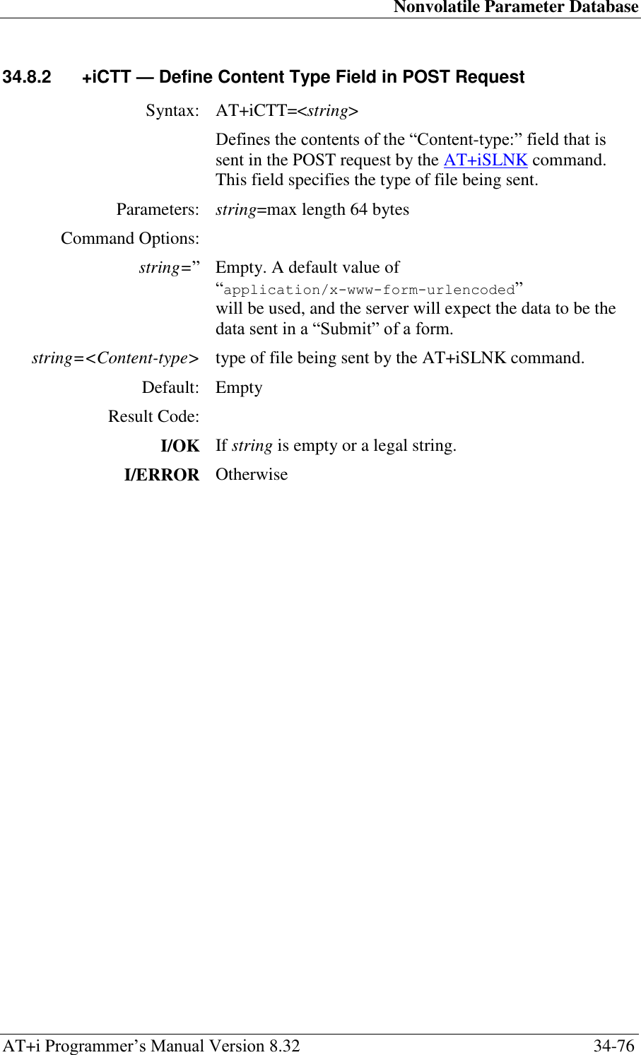
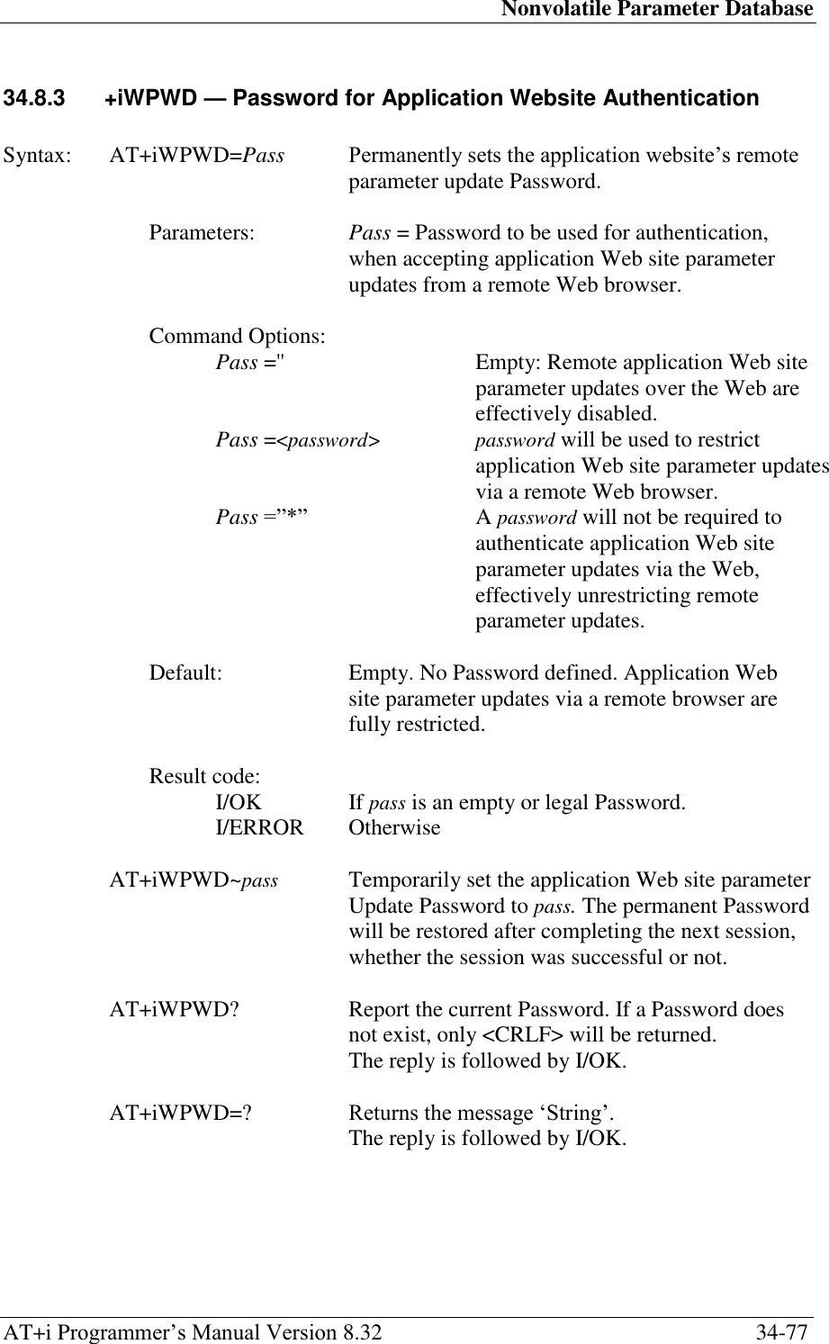
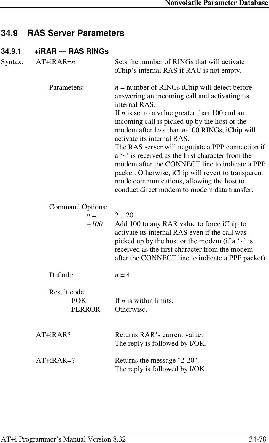
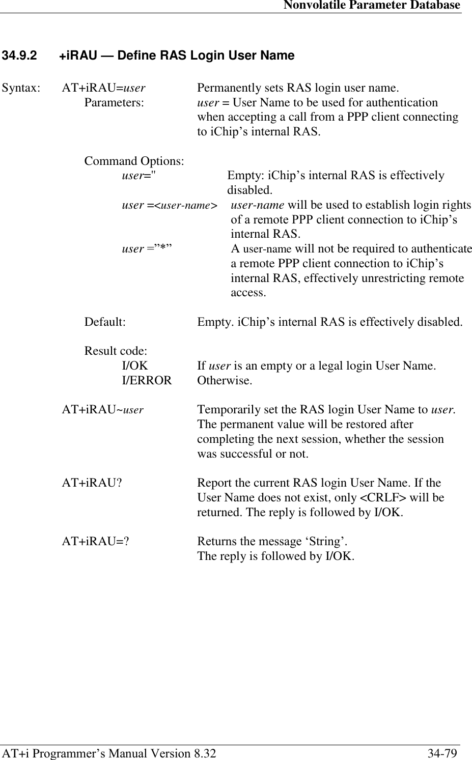
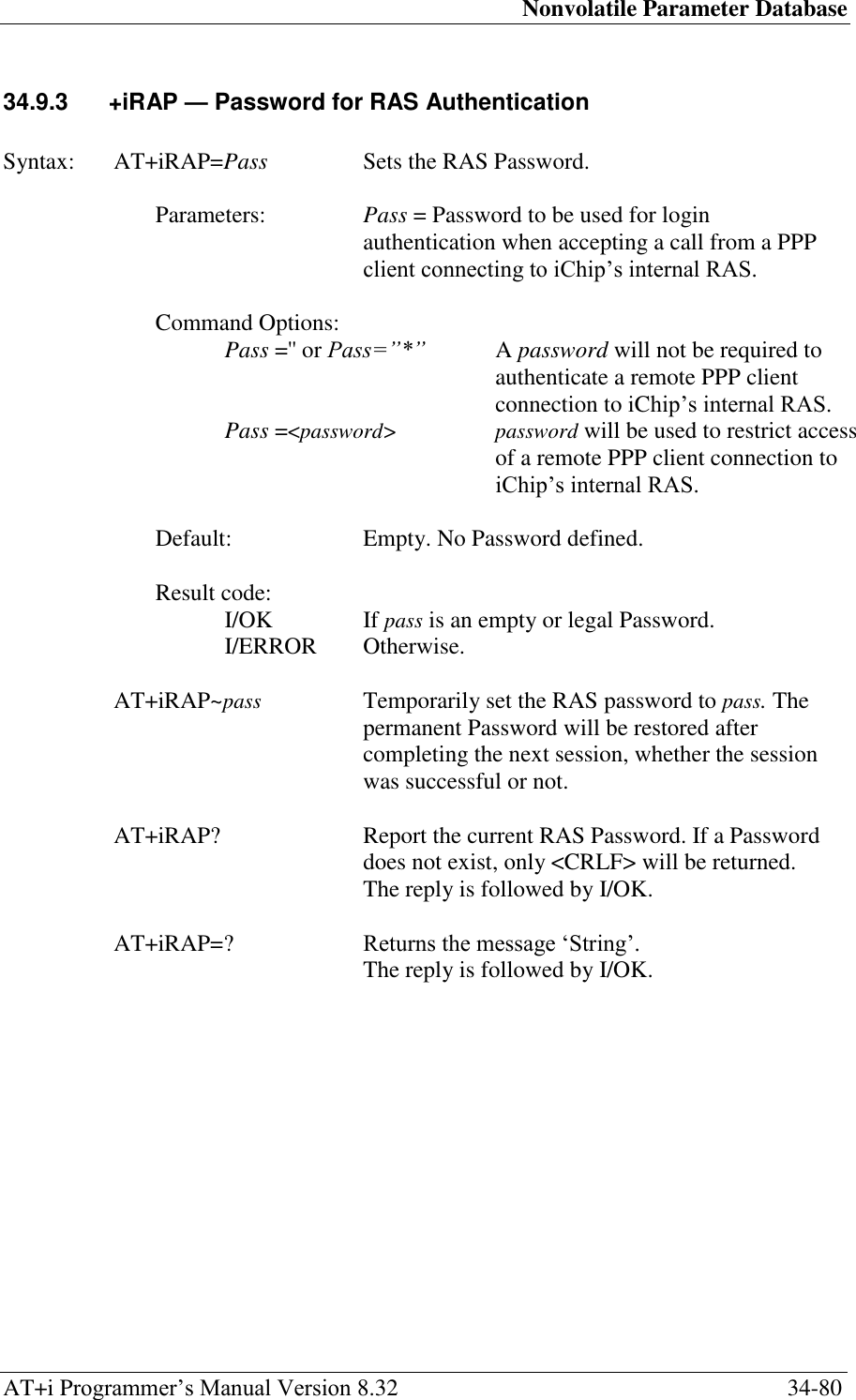
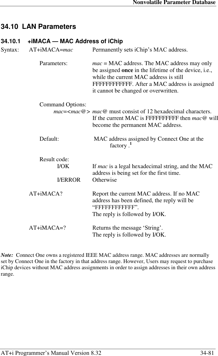
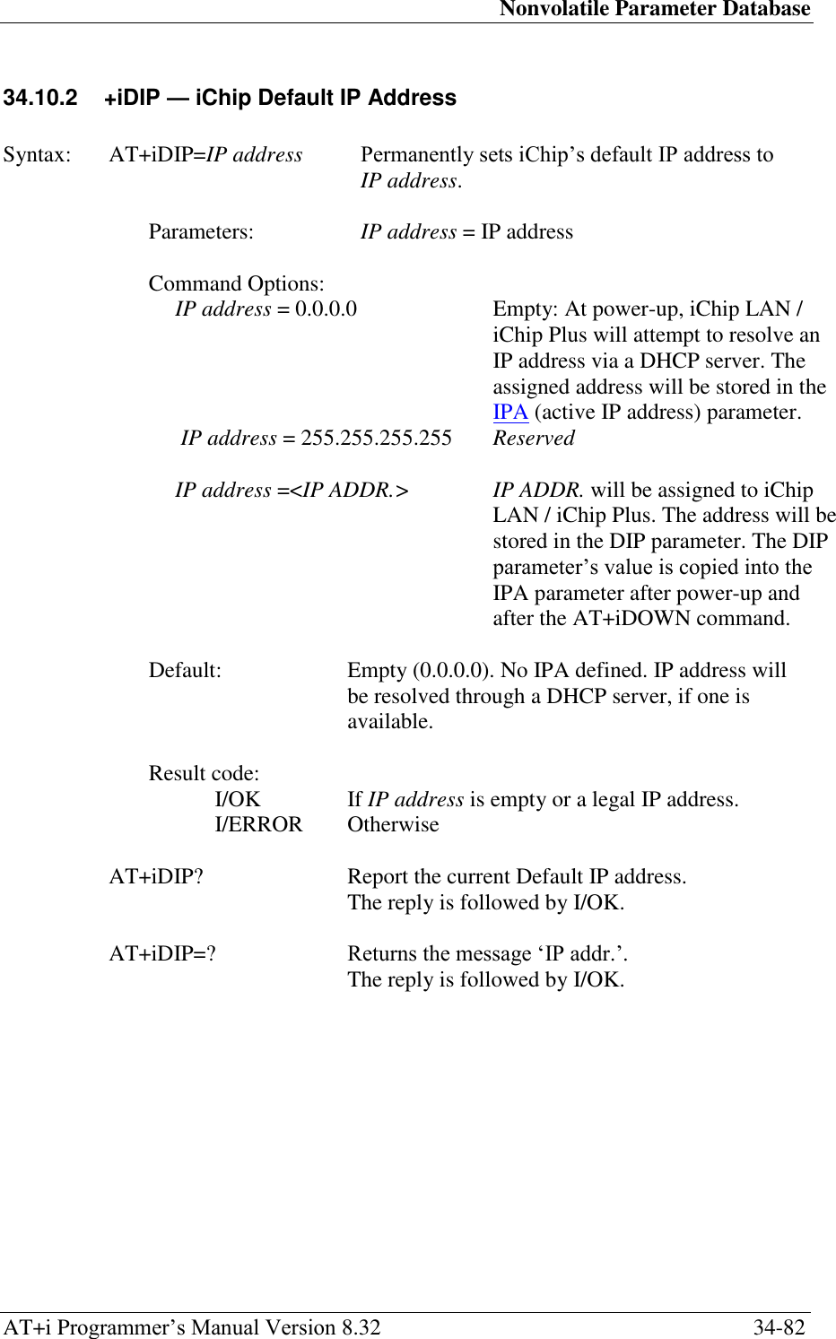
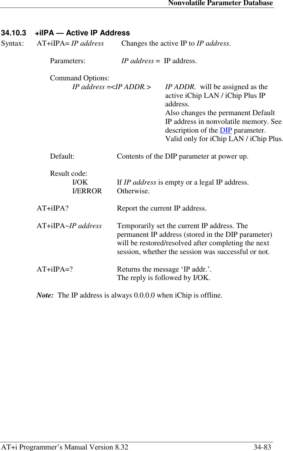
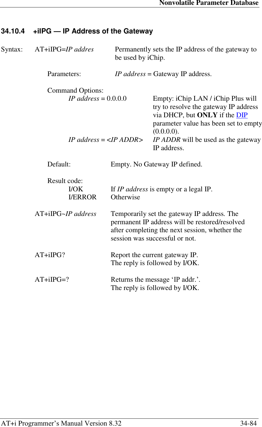
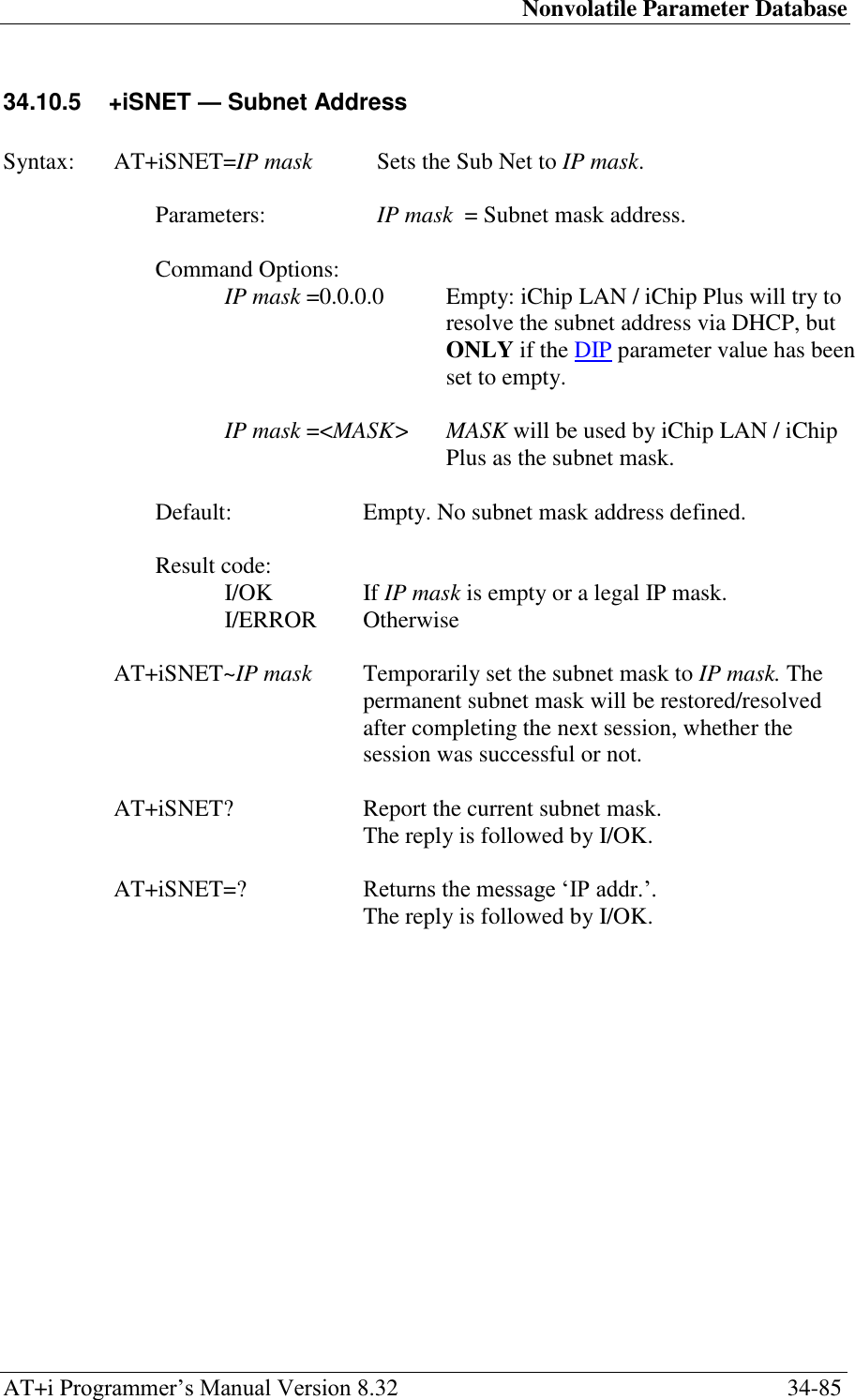
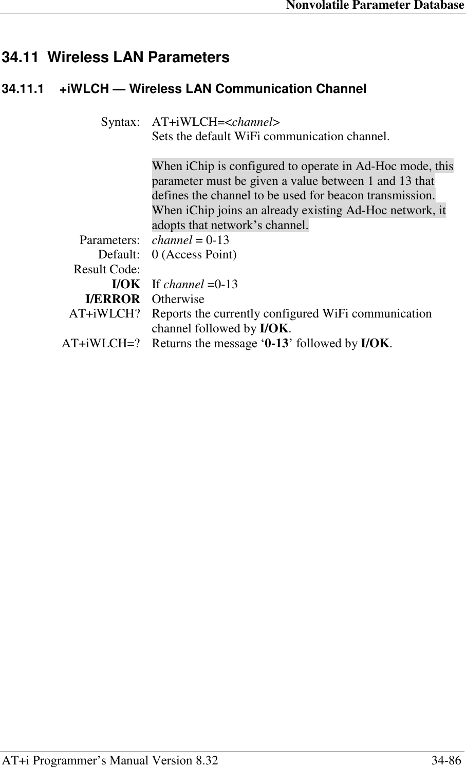
![Nonvolatile Parameter Database AT+i Programmer‘s Manual Version 8.32 34-90 34.11.5 +iWLKn — Wireless LAN WEP Key Array Syntax: AT+iWLKn=keyString Permanently sets the Wireless LAN WEP keys in the 4-slot WEP key array. Parameters: n = 1..4. keyString = WEP key string represented by a Hexadecimal ASCII string. Command Options: keyString='' Empty: No WEP key defined in position n. keyString=<key> key will be used as the key string value in position n. The identical value must be configured in the same position in the AP router. key must be a Hexadecimal representation string, where each byte is described by 2 ASCII characters in the range [‗0‘..‘9‘], [‗A‘..‘F‘] or [‗a‘..‘f‘]. When using 64-bit WEP (WLWM=1), key may contain up to 10 characters (defining 5 bytes). When using 128-bit WEP (WLWM=2), key may contain up to 26 characters (defining 13 bytes). Default: Empty. No WEP key defined. Result code: I/OK if keyString is an empty or legal WEP key string. I/ERROR otherwise AT+iWLKn~keyString Temporarily set WEP key n to keyString. The permanent value will be restored after completing the next session, both if the session was successful or not. AT+iWLKn? Report the current WEP key value in position n. The reported value will consist of '*' characters. The number of '*' characters shall reflect the number of characters in the actual key string. If the key string is empty, only <CRLF> will be returned. The reply is followed by I/OK. AT+iWLKn=? Returns the message ‗String‘. The reply is followed by I/OK.](https://usermanual.wiki/Connect-One/SM2144N1/User-Guide-1162098-Page-253.png)

![Nonvolatile Parameter Database AT+i Programmer‘s Manual Version 8.32 34-100 34.11.14 +iWKYn — Wireless LAN WEP Key Array Syntax: AT+iWKYn=<KeyString> Sets the Wireless LAN WEP key for each individual SSID in the array. Parameters: n=0-9 10 WEP keys, one for each SSID, respectively. Setting KeyString with n=0 is equivalent to setting WLKI and WLK1-WLK4 parameters. <KeyString> WEP key string represented by a hexadecimal ASCII string. Command Options: KeyString=‖ Empty KeyString=<key> key will be used as the KeyString value in position n. key must be a hexadecimal representation ASCII string, where each byte is described by two ASCII characters in the range [0.. 9], [A.. F] or [a.. f]. When using 64-bit WEP encryption (WLWM=1), key can contain up to 10 characters (defining 5 bytes). When using 128-bit WEP encryption (WLWM=2), key can contain up to 26 characters (defining 13 bytes). Default: Empty Result Code: I/OK If n is a legal value. I/ERROR Otherwise AT+iWKYn~key Temporarily sets WEP key in the nth position to key. AT+iWKYn? Reports the current WEP key value in position n. The reported value consists of (*) characters. The number of (*) characters reflects the number of characters in the actual key string. If the key string is empty, only <CRLF> is returned. The reply is followed by I/OK. AT+iWKYn=? Returns the message “String” followed by I/OK.](https://usermanual.wiki/Connect-One/SM2144N1/User-Guide-1162098-Page-263.png)
![Nonvolatile Parameter Database AT+i Programmer‘s Manual Version 8.32 34-106 34.12.4 +iRRRL — IP Registration Return Link Syntax: AT+iRRRL=IP[:Port] Permanently sets the IP registration Return Link IP and Web Port. Parameters: IP = IP address to use for registration after going online. Port = Port number to assign to iChip‘s Web server. See description of RRRL when registering IP. Command Options: IP = 0.0.0.0 Empty: No Return Link defined. IP = <IP_add> IP_addr will be used when registering after establishing an Internet session, rather than the iChip‘s actual local IP address. This is useful when the iChip receives an internal IP address behind a NAT. Assigning the NAT‘s IP address to IP_addr will allow reaching the iChip from the Internet. In SerialNET, the LPRT parameter may be pre-configured in the NAT to connect to the iChip device. See SerialNET Server Devices. Port = Web_port Optional port to map iChip‘s Web server in order to allow surfing iChip across a NAT in association with IP_addr. Default: Empty. No return link IP and Port defined. Result code: I/OK If IP is a legal IP address and Port is a legal IP port number. I/ERROR Otherwise. AT+iRRRL? Report the current return link IP and port. The reply is followed by I/OK. AT+iRRRL=? Returns the message ―Name/IP[:Port]‖. The reply is followed by I/OK.](https://usermanual.wiki/Connect-One/SM2144N1/User-Guide-1162098-Page-269.png)
![Nonvolatile Parameter Database AT+i Programmer‘s Manual Version 8.32 34-110 34.13.3 +iDSTR — Define Disconnection String for SerialNET Mode Syntax: AT+i[!]DSTR:<disconnect_string> Permanently sets SerialNET device disconnection string. In a modem environment, iChip also goes offline following this event. Parameters: disconnect_string = The string expected on a serial link to signal socket disconnection. Command Options: disconnect_string= '' Empty string – the connection will never be terminated due to a string arriving on serial link. disconnect_string=<string> string received on serial link signals socket disconnection. string consists any combination of printable ASCII characters and characters represented by two hexadecimal digits, such as: \xhh, where h is a hexadecimal digit 0..9 or A..F. Hexadecimal representation allows specifying non-printable characters. ! iChip will not send a DSTR to the socket upon detection. When this flag is not specified, iChip will send a DSTR each time it detects it. Default: Empty Result code: I/OK If disconnect_string is an empty or legal string. I/ERROR Otherwise AT+iDSTR? Reports the current contents of the disconnect_string parameter. If the disconnect_string parameter is empty, only <CRLF> are returned. If the ‗!‖ flag is specified, the ― *‖ string is appended to the report. For example, the reply to a AT+iDSTR? command will be ―&&& *‖ in case AT+i!DSTR=&&& was previously specified. The reply is followed by I/OK. AT+iDSTR=? Returns the message ‗String‘ followed by I/OK.](https://usermanual.wiki/Connect-One/SM2144N1/User-Guide-1162098-Page-273.png)
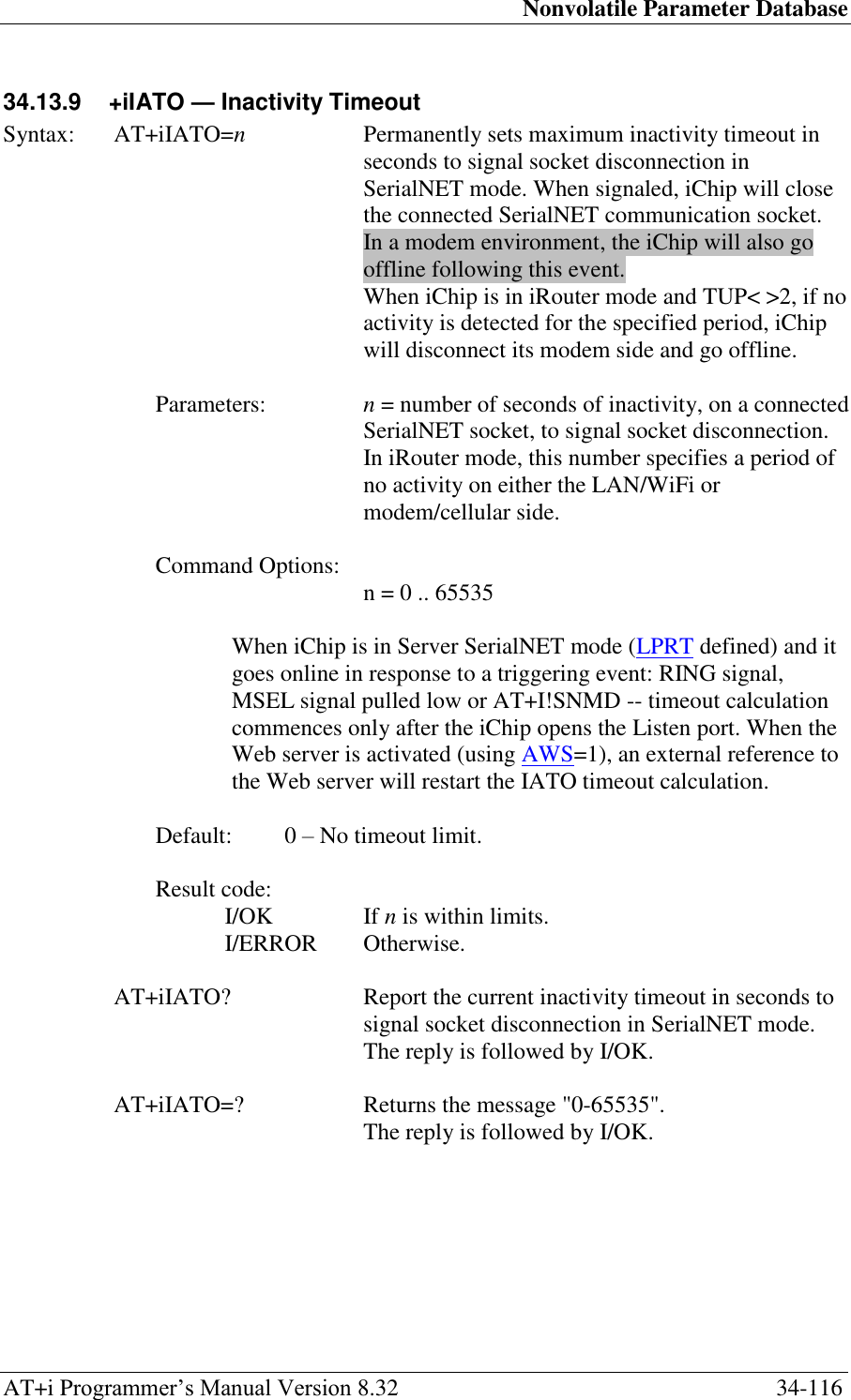
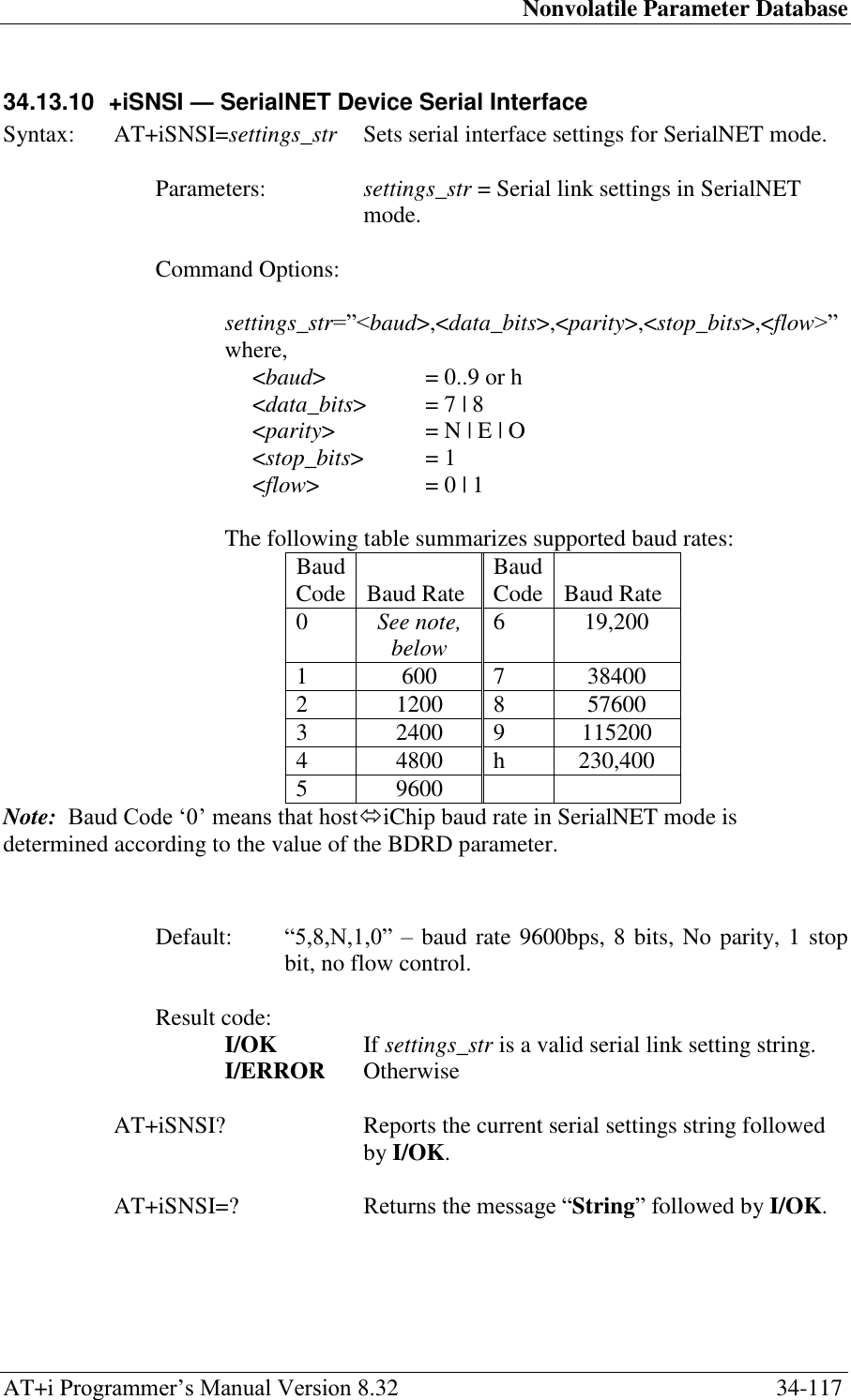
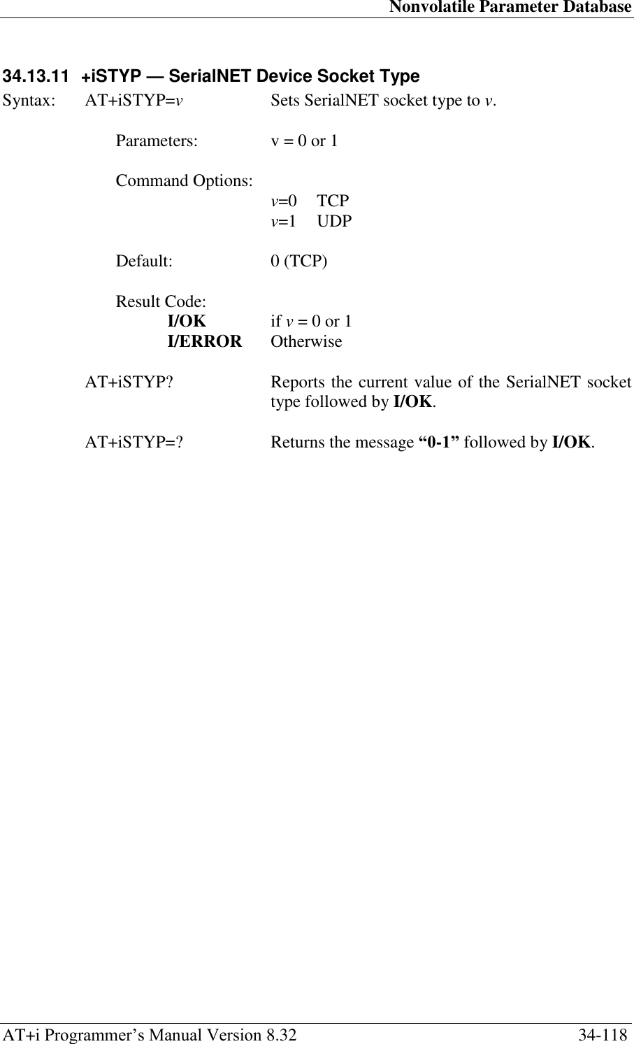
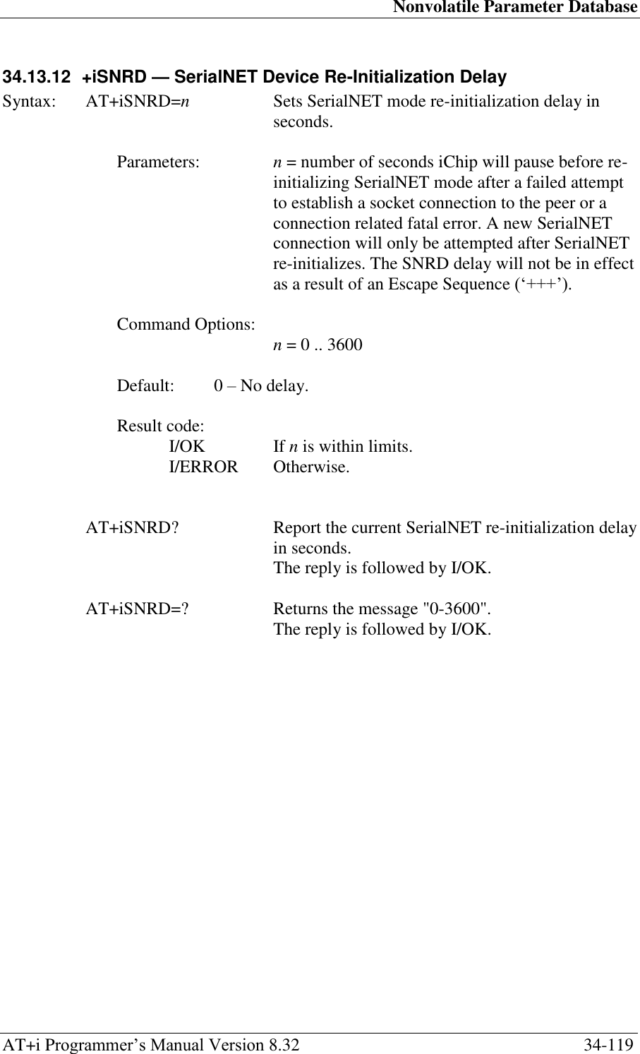
![Nonvolatile Parameter Database AT+i Programmer‘s Manual Version 8.32 34-121 34.13.14 +iSDT — SerialNET Dialup Timeout Syntax: AT+iSDT=n Permanently sets the SerialNET Dial timeout when waking up a remote SerialNET server. Parameters: n = Number of seconds to allow after dialing up the remote SerialNET server, before hanging up. Command Options: n = 0..255 [seconds]. Default: 20 [seconds] Result code: I/OK If n is within limits. I/ERROR Otherwise AT+iSDT? Report the current SerialNET dial timeout. The reply is followed by I/OK. AT+iSDT=? Returns the message "0-255". The reply is followed by I/OK.](https://usermanual.wiki/Connect-One/SM2144N1/User-Guide-1162098-Page-284.png)
![Nonvolatile Parameter Database AT+i Programmer‘s Manual Version 8.32 34-122 34.13.15 +iSWT — SerialNET Wake-Up Timeout Syntax: AT+iSWT=n Sets the SerialNET wake-up timeout when waking up a remote SerialNET server. Parameters: n = Number of seconds to allow the entire SerialNET server wakeup procedure before hanging up and retrying. Command Options: n = 0..65535 [seconds] Default: 600 [seconds]. Result code: I/OK If n is within limits. I/ERROR Otherwise AT+iSWT? Report the current SerialNET Wake-up timeout. The reply is followed by I/OK. AT+iSWT=? Returns the message ―0-65535‖. The reply is followed by I/OK.](https://usermanual.wiki/Connect-One/SM2144N1/User-Guide-1162098-Page-285.png)
![Nonvolatile Parameter Database AT+i Programmer‘s Manual Version 8.32 34-125 34.14.2 +iUSRV — Remote Firmware Update Server Name Syntax: AT+iUSRV=―<protocol>://<host>[:<port>]/[<relative_path>/]‖ Sets name of server to be used for updating iChip firmware remotely. This server must contain one or more firmware .imz files. The actual update process is initiated using the AT+iRFU command. Parameters: <protocol> = http or ftp <host> = Host name or IP address <port> = 1..65535 Default port for http is 80. Default port for ftp is 21. <relative_path> = Path to a directory which contains one or more .imz files on the host or a path to a text file containing a list of one or more <CRLF>-separated .imz filenames. relative_path must be relative to the FTP home directory. If relative_path contains sub-directories, they can be divided using either ‗\‘ or ‗/‘. absolute_path must end with ‗\‘ or ‗/‘. Command Options: AT+iUSRV=― Empty. No server name defined. Default: Empty. No dedicated remote firmware update server defined. Result Code: I/OK If host is an empty or legal host name. I/ERROR Otherwise AT+iUSRV~ ―<protocol>://<host>‖ Temporarily set the firmware update server name to host. The permanent value will be restored after completing the next session. AT+iUSRV? Report the current firmware update server name. If a server name is not defined, only <CRLF> will be returned. The reply is followed by I/OK. AT+iUSRV=? Returns the message ‗String / IP Addr‘ followed by I/OK. Example: at+iusrv="ftp://172.20.101.5:21/RFU_CO2128/"](https://usermanual.wiki/Connect-One/SM2144N1/User-Guide-1162098-Page-288.png)
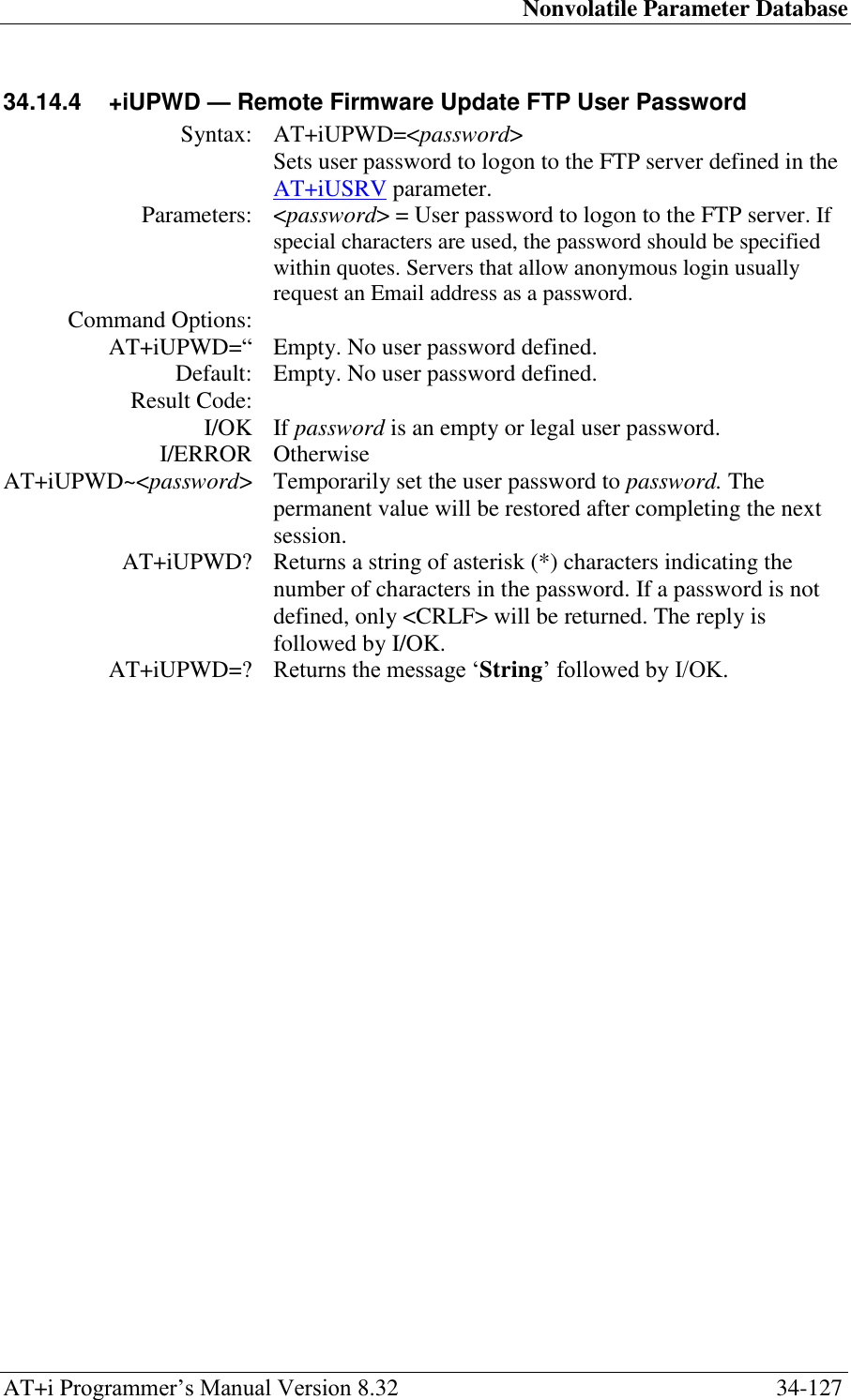
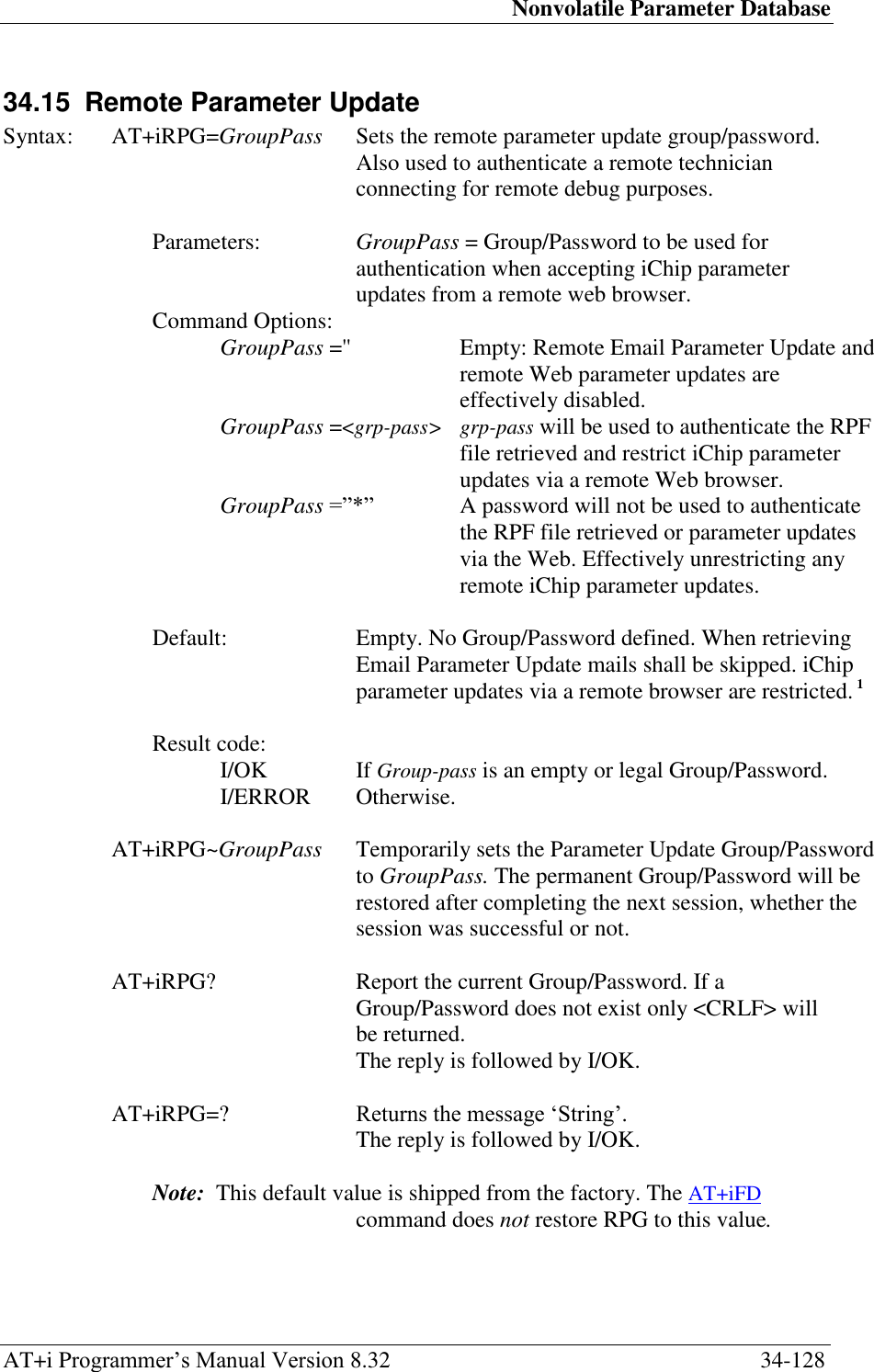
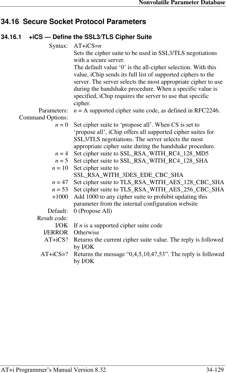
![Nonvolatile Parameter Database AT+i Programmer‘s Manual Version 8.32 34-130 34.16.2 +iCA — Define SSL3/TLS Certificate Authority Syntax: AT+iCA[n]=tca Sets the certificates of the trusted certificate authorities. This authority is the one eligible to sign a server‘s certificate. iChip accepts a server‘s identity only if its certificate is signed by one of these authorities. Parameters: tca = PEM format DER-encoded X509 certificate Command Options: tca =<CR><CR> Empty: No trusted certificate authority. tca =<cert> Optional n: cert is referenced as the trusted certificate authority‘s certificate during SSL3/TLS1 socket connection establishment (handshake). iChip establishes an SSL3/TLS1 socket connection only to servers having a certificate authenticated by this certificate authority. iChip expects cert to be multiple lines separated by <CR>, beginning with -----BEGIN CERTIFICATE----- and terminating with -----END CERTIFICATE-----. Maximum size of cert is 1300 characters. n is optional and may be 2, 3 or 4. Use n to specify alternative CA certificates (CA2, CA3 and CA4). When more than one CA certificates exist, iChip will check all its CA‘s when verifying a Server certificate. Default: Empty. No trusted Certificate Authority defined. Result code: I/OK If tca is an empty or legal certificate. I/ERROR Otherwise AT+iCA? Report the current trusted certificate contents. The reported value displays the Certificate Authority name, certificate validity date range, and the entire PEM contents. If the trusted certificate is empty, only <CRLF> is returned. The reply is followed by I/OK. AT+iCA=? Returns the message ‗String‘ followed by I/OK. Sample PEM format DER-encoded X509 certificate: -----BEGIN CERTIFICATE----- MIICPDCCAaUCEHC65B0Q2Sk0tjjKewPMur8wDQYJKoZIhvcNAQECBQAwXzELMAkG A1UEBhMCVVMxFzAVBgNVBAoTDlZlcmlTaWduLCBJbmMuMTcwNQYDVQQLEy5DbGFz cyAzIFB1YmxpYyBQcmltYXJ5IENlcnRpZmljYXRpb24gQXV0aG9yaXR5MB4XDTk2 MDEyOTAwMDAwMFoXDTI4MDgwMTIzNTk1OVowXzELMAkGA1UEBhMCVVMxFzAVBgNV BAoTDlZlcmlTaWduLCBJbmMuMTcwNQYDVQQLEy5DbGFzcyAzIFB1YmxpYyBQcmlt YXJ5IENlcnRpZmljYXRpb24gQXV0aG9yaXR5MIGfMA0GCSqGSIb3DQEBAQUAA4GN ADCBiQKBgQDJXFme8huKARS0EN8EQNvjV69qRUCPhAwL0TPZ2RHP7gJYHyX3KqhE BarsAx94f56TuZoAqiN91qyFomNFx3InzPRMxnVx0jnvT0Lwdd8KkMaOIG+YD/is I19wKTakyYbnsZogy1Olhec9vn2a/iRFM9x2Fe0PonFkTGUugWhFpwIDAQABMA0G CSqGSIb3DQEBAgUAA4GBALtMEivPLCYATxQT3ab7/AoRhIzzKBxnki98tsX63/Do lbwdj2wsqFHMc9ikwFPwTtYmwHYBV4GSXiHx0bH/59AhWM1pF+NEHJwZRDmJXNyc AA9WjQKZ7aKQRUzkuxCkPfAyAw7xzvjoyVGM5mKf5p/AfbdynMk2OmufTqj/ZA1k -----END CERTIFICATE-----](https://usermanual.wiki/Connect-One/SM2144N1/User-Guide-1162098-Page-293.png)
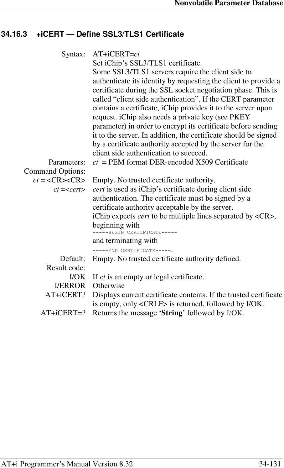
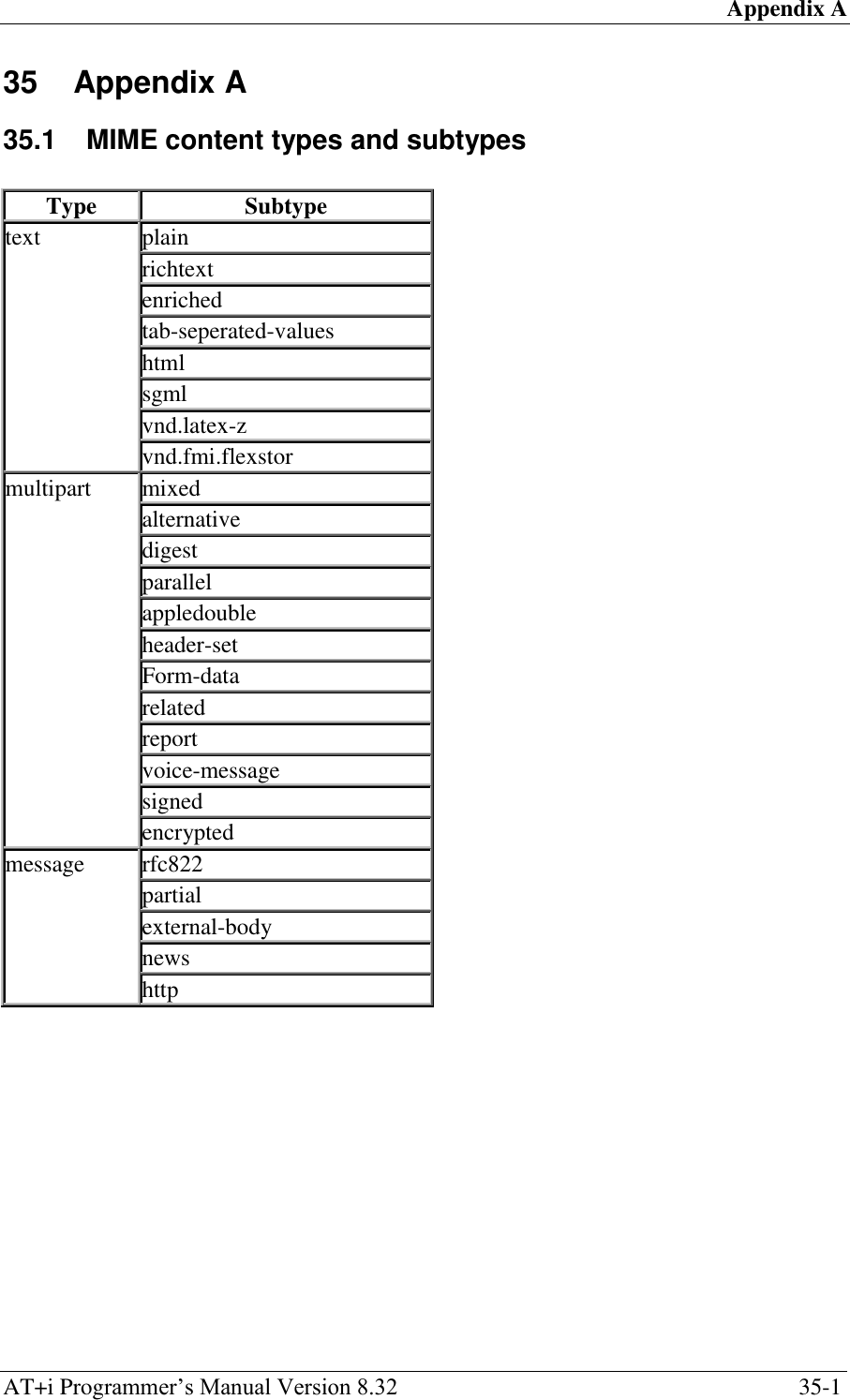
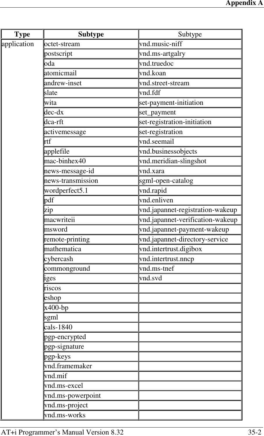
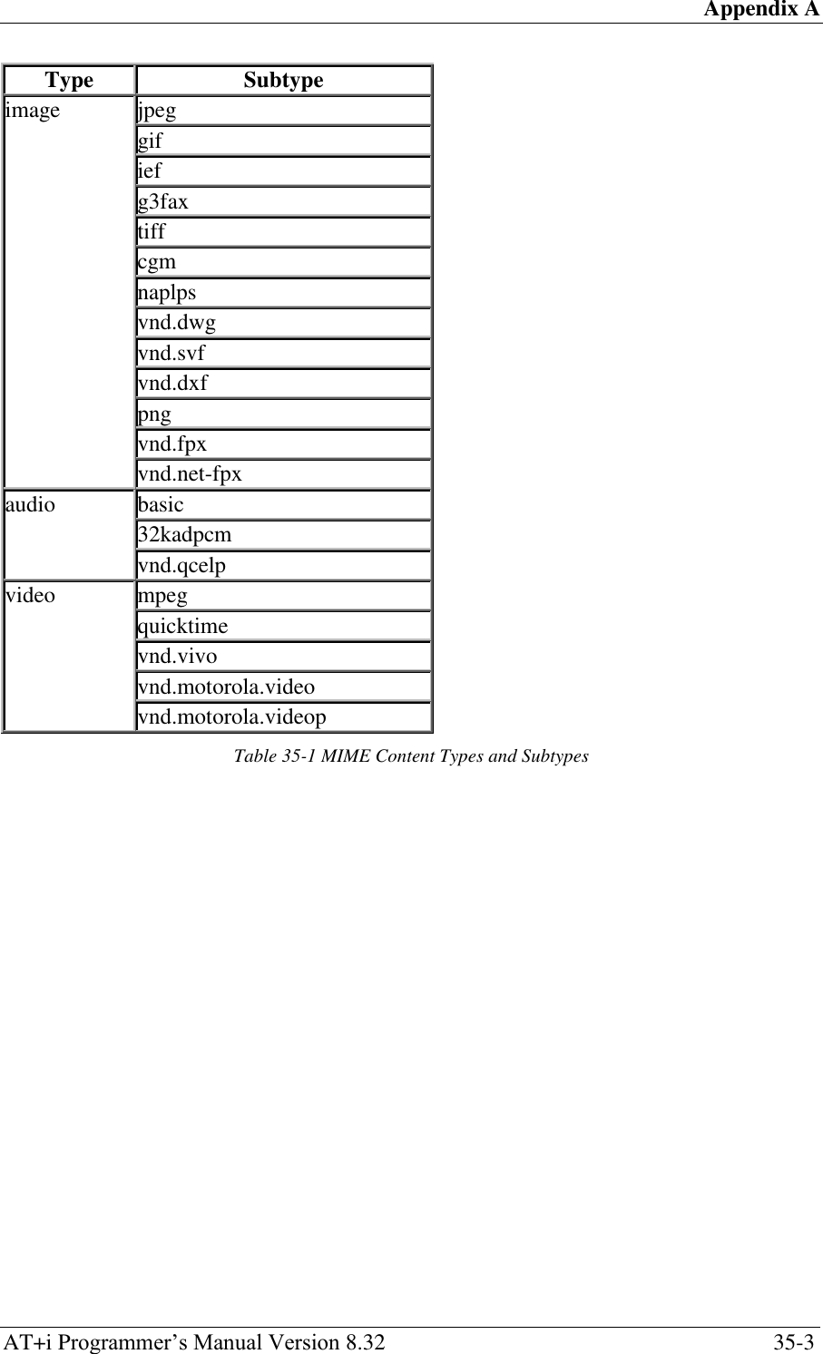
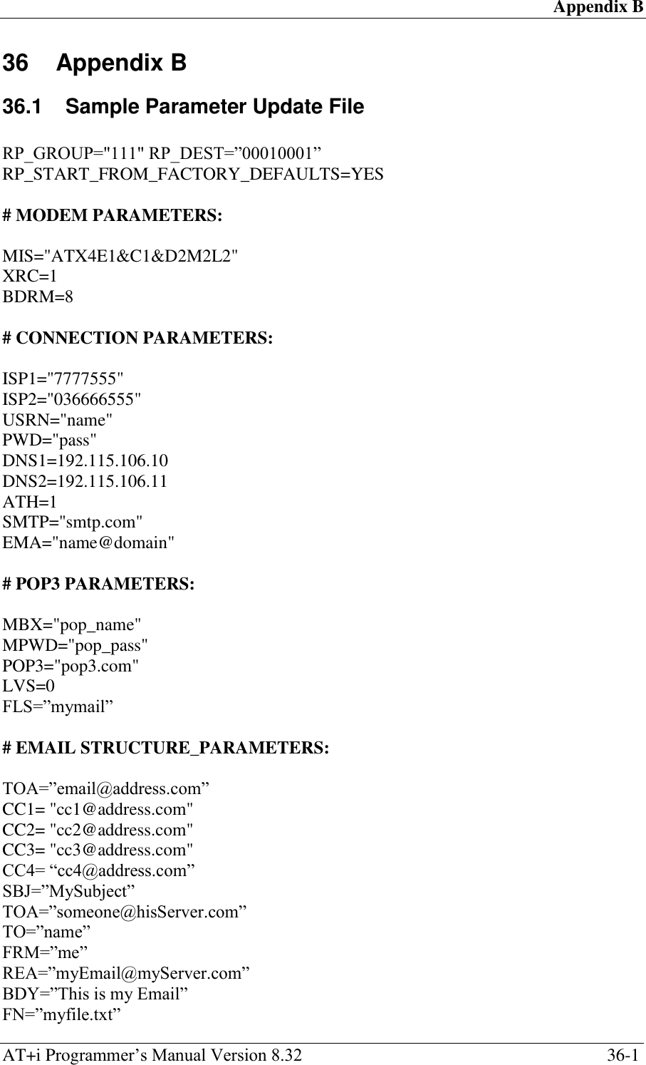
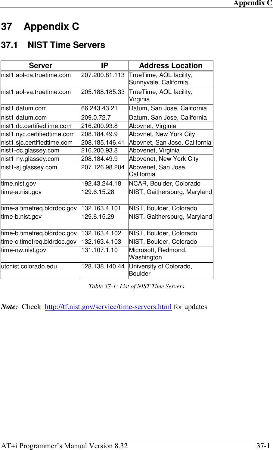
![Index AT+i Programmer‘s Manual Version 8.32 38-1 38 Index +i[@]FOPN – FTP Open Session ................. 11-1 +i[@]FOPS – Secure FTP Open Session ..... 21-5 +iADCD - ADC Delta ................................ 34-32 +iADCL - ADC Level ................................ 34-31 +iADCP - ADC GPIO Pin .......................... 34-34 +iADCT - ADC Polling Time .................... 34-33 +iARS – Automatic Router Start .............. 34-135 +iATH - Set PPP Authentication Method .. 34-39 +iAWS - Activate WEB Server Automatically .............................................................. 34-21 +iBDRA - Forces iChip into Auto Baud Rate Mode ......................................................... 5-1 +iBDRD - Baud Rate Divider .................... 34-20 +iBDRF - Define A Fixed Baud Rate on Host Connection ............................................ 34-18 +iBDRM - Define A Fixed Baud Rate on iChip Modem Connection ......................... 34-19 +iCA - Define SSL3/TLS Certificate Authority ............................................................ 34-130 +iCCn - Define Alternate Addressee <n> .. 34-70 +iCERT - Define SSL3/TLS1 Certificate . 34-131 +iCKSM – Checksum Mode ...................... 34-28 +iCPF – Active Communications Platform 34-24 +iCS - Define the SSL3/TLS Cipher Suite ........... ............................................................ 34-129 +iCTT – Define Content Type Field in POST Request ................................................. 34-76 +iDELF – Email Delete Filter String.......... 34-64 +iDF – IP Protocol ‗Don‘t Fragment‘ Bit Value .............................................................. 34-27 +iDIP - iChip Default IP Address ............... 34-82 +iDMD – Modem Dial Mode ....................... 34-9 +iDNSn - Define Domain Name Server IP Address ................................................. 34-45 +iDOWN - Terminate Internet Session .......... 5-5 +iDPSZ – DHCP Server Pool Size ........... 34-133 +iDSLT – DHCP Server Lease Time ....... 34-134 +iDSTD - Define Daylight Savings Transition Rule ....................................................... 34-56 +iDSTR - Define Disconnection String for SerialNET Mode ................................. 34-110 +iE* - Terminate Binary E-Mail .................... 6-4 +iEMA - Accept ASCII-Coded Lines for Immediate E-Mail Send ............................ 6-1 +iEMB - Accept Binary Data for Immediate E-Mail Send .............................................. 6-2 +iFAPN – FTP Open File for Appending ..... 11-9 +iFCHR — Flush Character ..................... 34-114 +iFCLF – FTP Close File ........................... 11-11 +iFCLS – FTP Close Session ..................... 11-13 +iFCWD – FTP Change Working Directory 11-5 +iFD - Restore All Parameters to Factory Defaults ................................................... 34-7 +iFDEL – FTP Delete File ......................... 11-12 +iFDL – FTP Directory Listing .................... 11-2 +iFDNL – FTP Directory Names Listing ..... 11-3 +iFLS - Define Filter String ....................... 34-63 +iFLW - Set Flow Control Mode ............... 34-23 +iFMKD – FTP Make Directory .................. 11-4 +iFN - Attachment File Name .................... 34-73 +iFRCV – FTP Receive File ........................ 11-7 +iFRM - Email ‗From‘ Description/Name . 34-69 +iFSND – FTP Send File Data ................... 11-10 +iFSTO – FTP Open File for Storage ........... 11-8 +iFSZ – FTP File Size .................................. 11-6 +iGMTO - Define Greenwich Mean Time Offset .............................................................. 34-55 +iGPNM - Get Peer Name for A Specified Socket.................................................... 13-11 +iHDL - Limit Number of Header Lines .... 34-62 +iHIF – Host Interface ................................ 34-29 +iHSRV | +iHSRn - Host Server Name/IP 34-108 +iHSS - Assign Special Characters to Hosts ........ ............................................................ 34-109 +iHSTN - iChip LAN Host Name ............ 34-107 +iIATO - Inactivity Timeout .................... 34-116 +iIPA - Active IP Address .......................... 34-83 +iIPG - IP Address of the Gateway ............ 34-84 +iISPn - Set ISP Phone Number ................. 34-38 +iLATI – TCP/IP Listening Socket to Service Remote AT+i Commands ..................... 34-22 +iLPRT - SerialNET Device Listening Port ......... ............................................................ 34-111 +iLSST - Get A Listening Socket‘s Active Connection Status ................................... 13-4 +iLTCP - Open A TCP Listening Socket ..... 13-3 +iLVS – ‗Leave on Server‘ flag ................. 34-44 +iMACA - MAC Address of iChip ............ 34-81 +iMBTB - Max Bytes To Buffer .............. 34-112 +iMBX - Define POP3 Mailbox Name ...... 34-51 +iMCBF - Maximum Characters before Socket Flush.................................................... 34-115 +iMCM - Issue Intermediate Command to Modem .................................................... 14-1 +iMIF – Modem Interface .......................... 34-30 +iMIS - Modem Initialization String .......... 34-10 +iMPS - Max PPP Packet Size ................... 34-16 +iMPWD - Define POP3 Mailbox Password ....... .............................................................. 34-52 +iMST - Media Subtype String .................. 34-72 +iMT - Media Type Value .......................... 34-71 +iMTTF - Max Timeout to Socket Flush . 34-113 +iMTYP - Set Type of Modem Connected to iChip...................................................... 34-11 +iNTOD - Define Network Time-of-Day Activation Flag...................................... 34-54 +iNTSn - Define Network Time Server ..... 34-53 +iPDSn - Define PING Destination Server 34-57 +iPFR - PING Destination Server Polling Frequency .............................................. 34-58](https://usermanual.wiki/Connect-One/SM2144N1/User-Guide-1162098-Page-305.png)
![Index AT+i Programmer‘s Manual Version 8.32 38-2 +iPGT - PING Timeout .............................. 34-15 +iPING - Send a PING Request to a Remote Server ........................................................ 5-6 +iPKEY - Define iChip‘s Private Key...... 34-132 +iPOP3 - Define POP3 Server Name ......... 34-50 +iPSE – Set Power Save Mode ................... 34-25 +iPTD - SerialNET Packets to Discard .... 34-123 +iPWD - Define Connection Password ...... 34-41 +iRAP - Password for RAS Authentication ......... .............................................................. 34-80 +iRAS – RAS RINGs ................................. 34-78 +iRAU - Define RAS Login User Name .... 34-79 +iRDL - Number of Times to Redial ISP ... 34-42 +iREA - Return Email Address .................. 34-68 +iRFU - Remote Firmware Update .............. 25-3 +iRLNK - Retrieve Link ................................ 8-1 +iRMH - Retrieve Mail Header ...................... 7-2 +iRML - Retrieve Mail List............................ 7-1 +iRMM - Retrieve Mail Message ................... 7-3 +iRP - Report Status ....................................... 4-1 +iRPG – Remote Parameter Update Group .......... ............................................................ 34-128 +iRRA - iChip Readiness Report Activation ........ .............................................................. 34-35 +iRRHW - iChip Readiness Hardware Pin 34-37 +iRRMA - IP Registration Mail Address . 34-103 +iRRRL - IP Registration Return Link ..... 34-106 +iRRSV - IP Registration Host Server Name ....... ............................................................ 34-104 +iRRWS - IP Registration Web Server .... 34-105 +iRTO - Delay Period between Redials to ISP .............................................................. 34-43 +iSBJ - Email Subject Field ....................... 34-65 +iSCLS - Close Socket ............................... 13-14 +iSCS - Get A Socket Connection Status Report ................................................................ 13-6 +iSDM – Service Diabling Mode ............... 34-26 +iSDMP - Dump Socket Buffer ................. 13-12 +iSDT - SerialNET Dialup Timeout......... 34-121 +iSFSH[%] - Flush Socket‘s Outbound Data ....... .............................................................. 13-13 +iSLNK – Submit A POST Request to A Web Server ........................................................ 8-3 +iSMA - SMTP Authentication Method .... 34-47 +iSMP - Define SMTP Login Password .... 34-49 +iSMTP - Define SMTP Server Name ....... 34-46 +iSMU – Define SMTP Login User Name 34-48 +iSNET – Subnet Address .......................... 34-85 +iSNET – Subnet address of iChip LAN ... 34-88 +iSNMD - Activate SerialNET Mode ............ 9-1 +iSNRD - SerialNET Device Re-Initialization Delay ................................................... 34-119 +iSNSI - SerialNET Device Serial Interface ........ ............................................................ 34-117 +iSPN - SerialNET Server Phone Number ........... ............................................................ 34-120 +iSRCV - Receive A Byte Stream from A Socket‘s Input Buffer .............................. 13-9 +iSSL – Secure Socket Connection Handshake ................................................................ 21-4 +iSSND[%] - Send A Byte Stream to A Socket ................................................................ 13-7 +iSST - Get A Single Socket Status Report . 13-5 +iSTCP - Open and Connect A TCP Socket 13-1 +iSTYP - SerialNET Device Socket Type 34-118 +iSUDP - Open A connectionless UDP socket ................................................................ 13-2 +iSWT - SerialNET Wake-Up Timeout ... 34-122 +iTBSN[%] - Telnet Send A Byte Stream .... 12-4 +iTCLS - Telnet Close Session .................... 12-6 +iTFSH[%] - Flush Telnet Socket‘s Outbound Data ......................................................... 12-5 +iTO - Email ‗To‘ Description/Name ........ 34-67 +iTOA - Define Primary Addressee ........... 34-66 +iTOPN – Telnet Open Session ................... 12-1 +iTRCV – Telnet Receive Data .................... 12-2 +iTSND - Telnet Send Data Line ................. 12-3 +iTTO – TCP Timeout ............................... 34-14 +iTTR - TCP Retransmit Timeout .............. 34-17 +iTUP - Triggered Internet Session Initiation 5-3 +iUEN - Remote Firmware Update Flag .. 34-124 +iUFn - User Fields and Macro Substitution ........ .............................................................. 34-59 +iUP - Initiate Internet Session....................... 5-2 +iUPWD – Remote Firmware Update FTP User Password ............................................. 34-127 +iURL - Default URL Address ................... 34-75 +iUSRN - Define Connection User Name .. 34-40 +iUSRV - Remote Firmware Update Server Name ................................................... 34-125 +iUUSR - Remote Firmware Update FTP User Name ................................................... 34-126 +iWKYn - Wireless LAN WEP Key Array .......... ............................................................ 34-100 +iWLBM - WLAN B Mode ......................... 15-7 +iWLCH - Wireless LAN Communication Channel ................................................. 34-86 +iWLGM - WLAN G Mode ......................... 15-8 +iWLKI - Wireless LAN Transmission WEP Key Index .............................................. 34-89 +iWLKn - Wireless LAN WEP Key Array 34-90 +iWLPP – Personal Shared Key Pass-Phrase ....... .............................................................. 34-92 +iWLPS - Wireless LAN Power Save ........ 34-91 +iWLPW - Set WLAN Tx Power ................. 15-3 +iWLSI - Wireless LAN Service Set Identifier .............................................................. 34-87 +iWLTR - Wireless LAN Transmission Rate ...... ................................................................ 15-2 +iWLWM - Wireless LAN WEP Mode ..... 34-88 +iWNXT - Retrieve Next Changed Web Parameter ................................................ 10-2 +iWPPn - Pre-Shared Key Passphrase Array ....... .............................................................. 34-99 +iWPSI - Periodic WiFi Scan Interval ....... 34-94](https://usermanual.wiki/Connect-One/SM2144N1/User-Guide-1162098-Page-306.png)