Corning Optical Communication Wireless VEAWSM VE DISTRIBUTED ANTENNA SYSTEM User Manual EnCOVER Dual Band
Corning Optical Communication Wireless VE DISTRIBUTED ANTENNA SYSTEM EnCOVER Dual Band
UserManual.wiki
>
Corning Optical Communication Wireless
>
VEAWSM User Manual
Users Manual
Navigation menu
Upload a User Manual
Namespaces
Wiki Guide
HTML
PDF
Info
Views
User Manual
Discussion / Help
Navigation
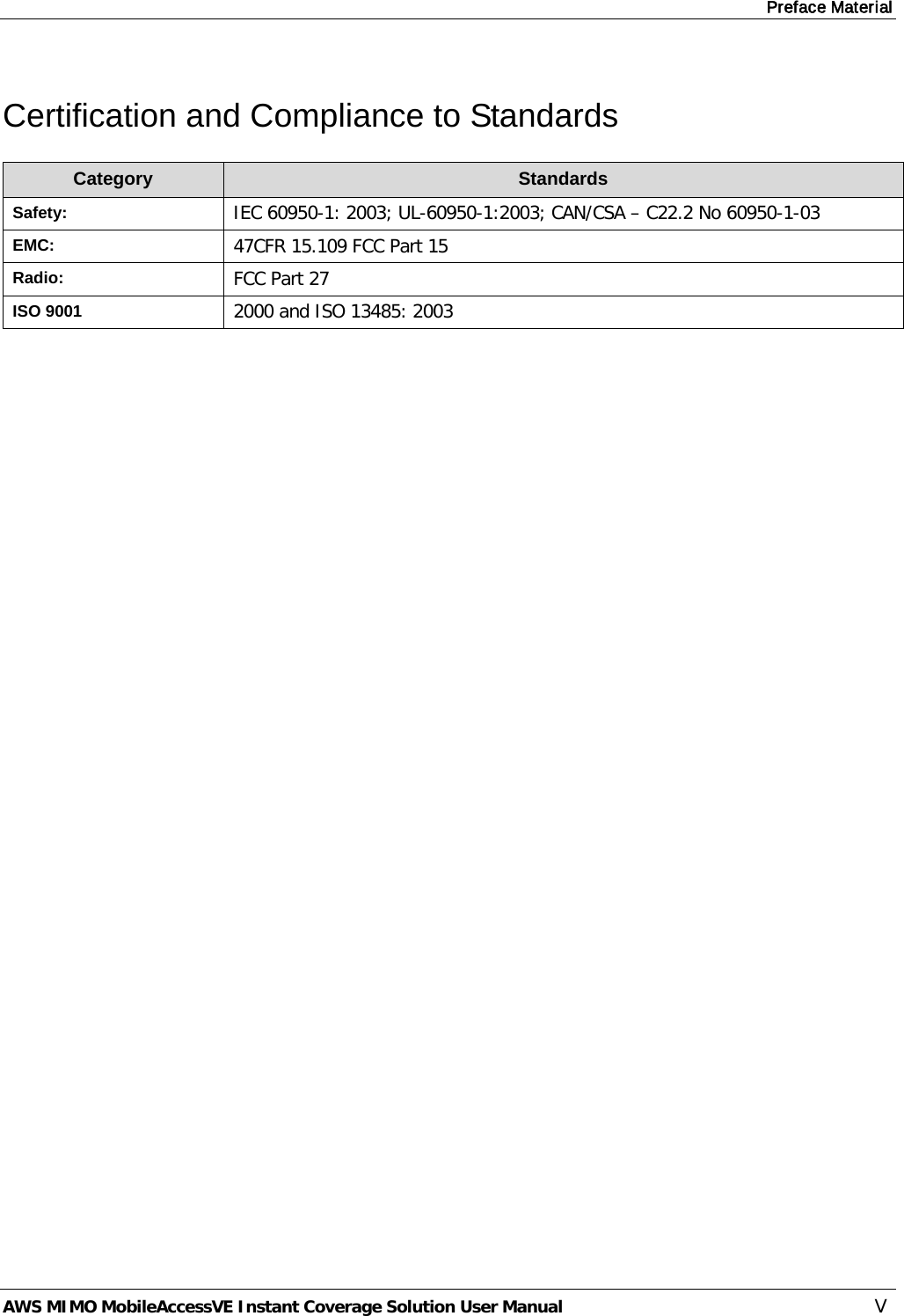
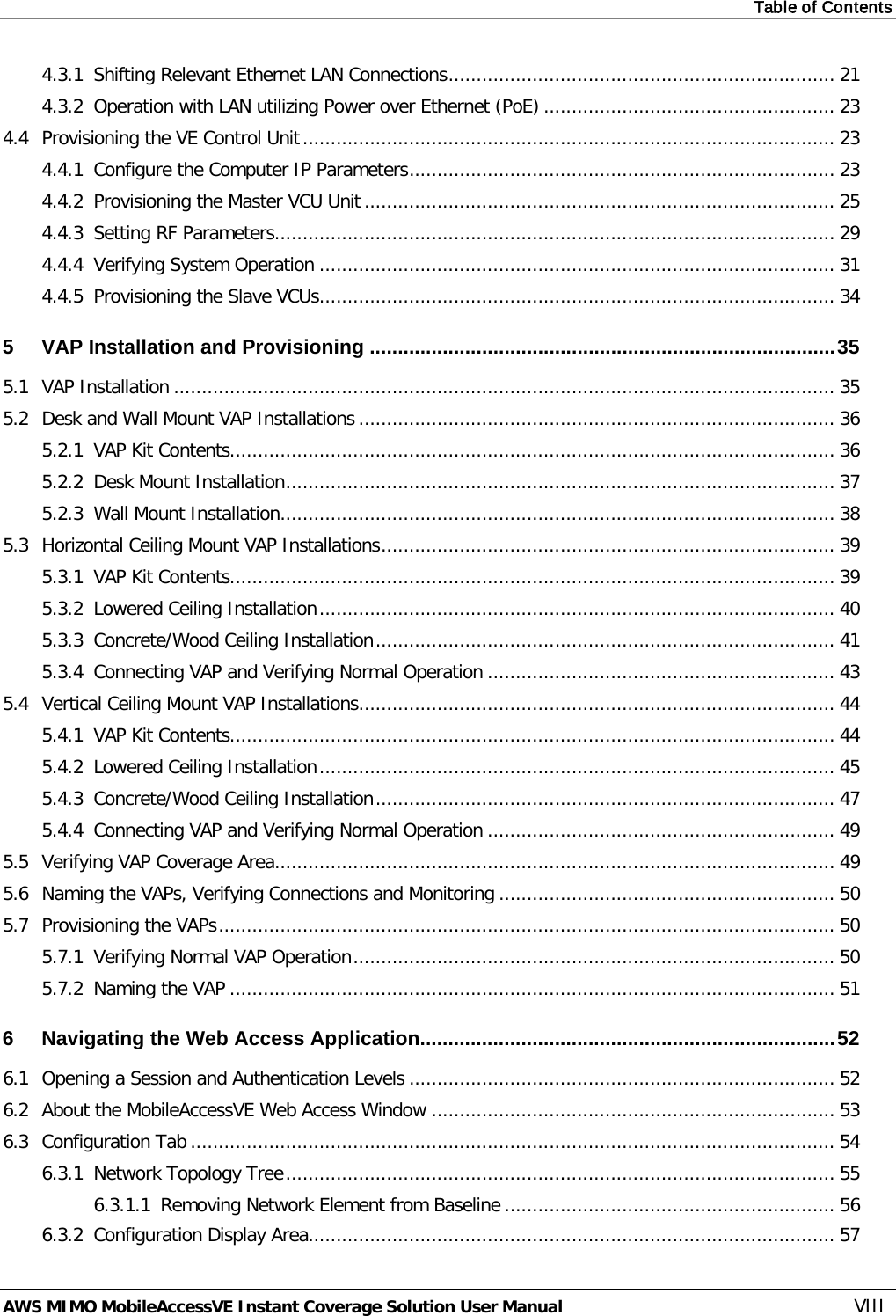
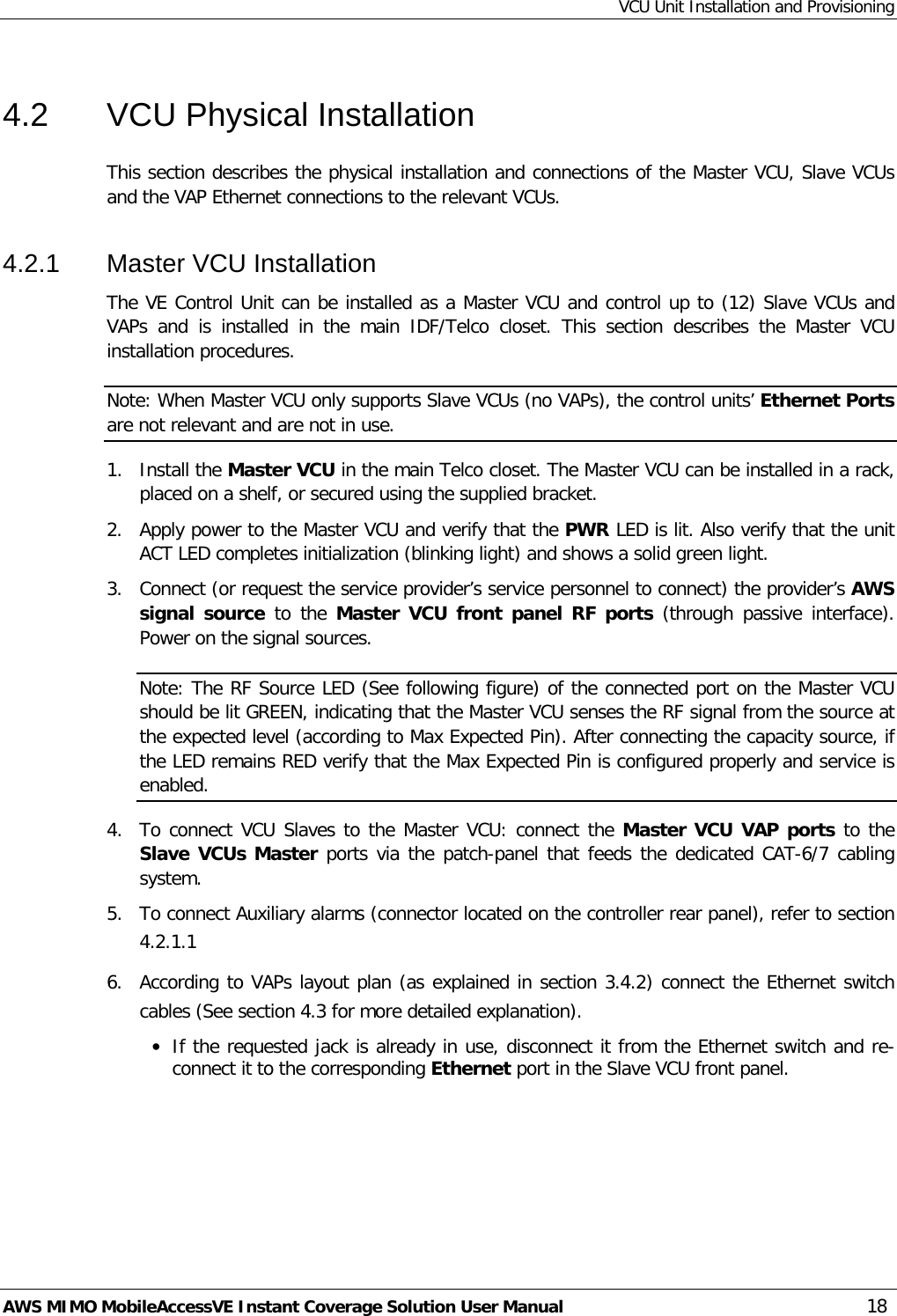
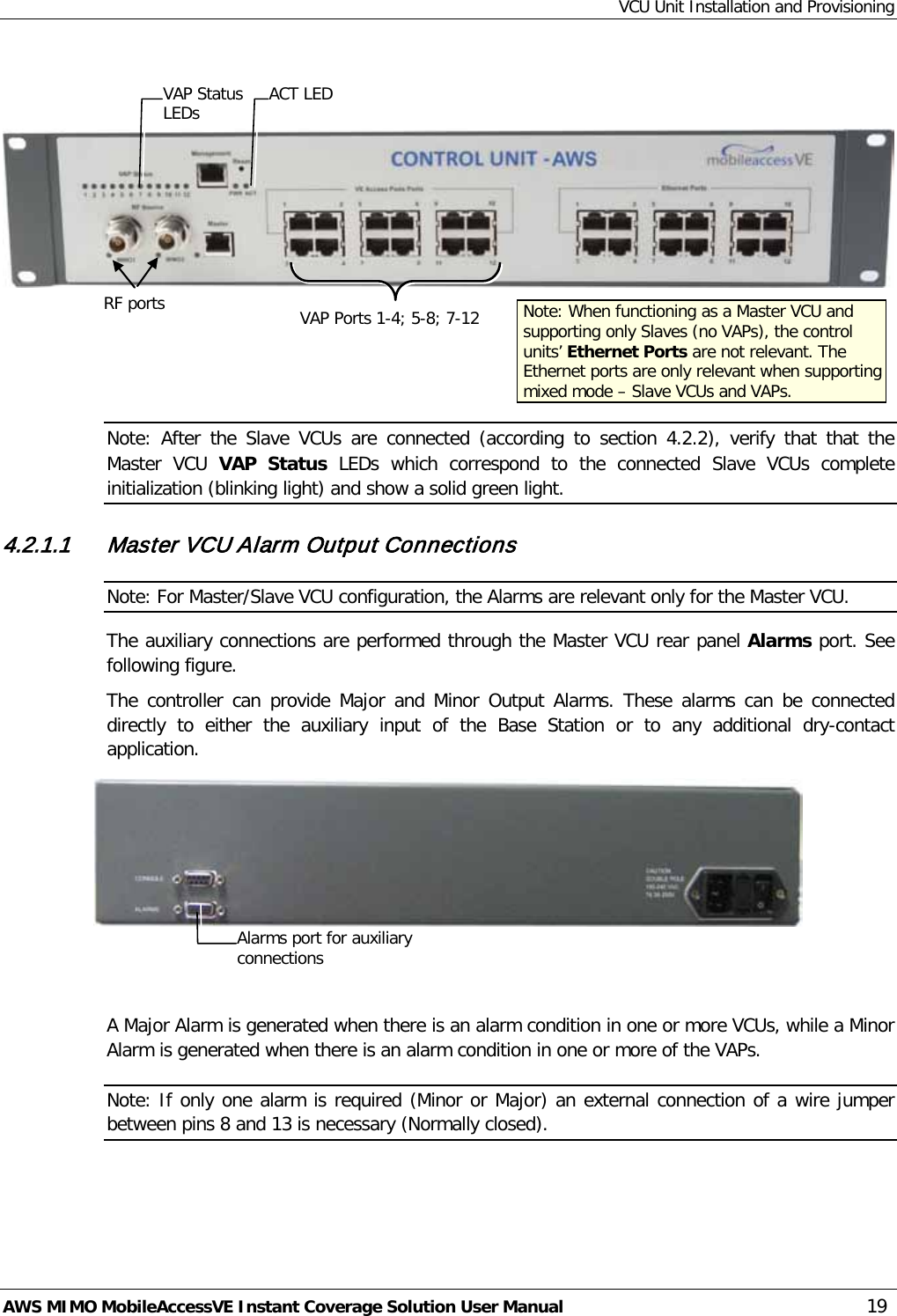
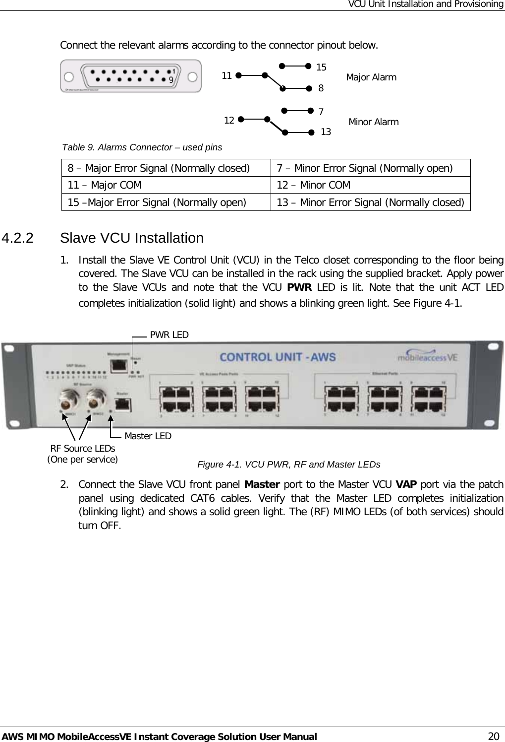
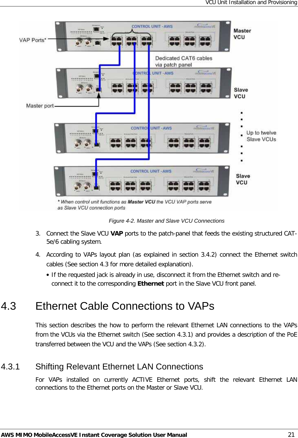
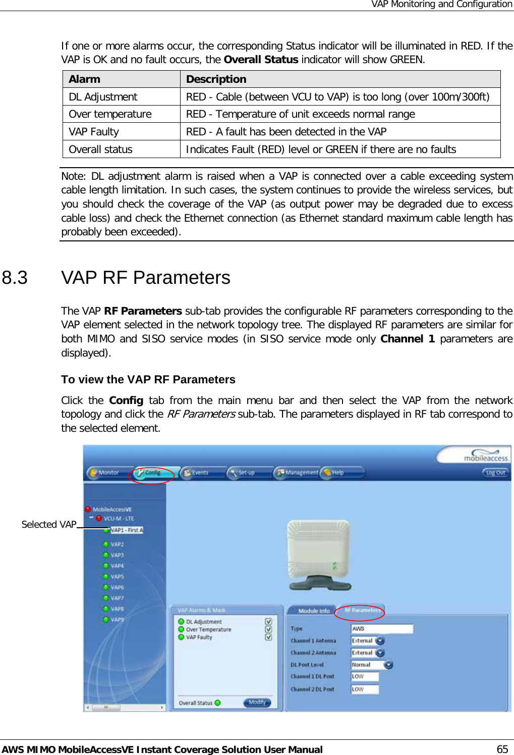
![VAP Installation and Provisioning AWS MIMO MobileAccessVE Instant Coverage Solution User Manual 39 5.3 Horizontal Ceiling Mount VAP Installations Note: The VAP and required RJ-45 cable are supplied in the provided VE AWS VAP kit (See 5.2.1). The Horizontal installation procedure varies depending on the type of ceiling: • Lowered ceilings – See 5.3.2. • Concrete/Wood ceilings – See 5.3.3. 5.3.1 VAP Kit Contents Please verify that the VAP Ceiling Mount Installation kit (P/N AK-VAP-CEILING-MT-H) includes the items listed below. Table 11: Horizontal Ceiling Mount VAP Kit Kit Items Description UNIT Mounting Brackets A) Ceiling Bracket B) Locke Bracket “Twist on” Track Light Clip assembly Used for installation on lowered ceilings. A) Track light Track Light Clip B) Screw, Bolt and Washer 3 x Screw,Flat Head, 100', 4/40 x 1/4 [NEROSTA] Used for assembling brackets together 4 x Self Screw,3dim L=8 ,Flat HD 90', PHILIPS, [steel zinc] Used Used to secure bracket assembly to VAP A B A B](https://usermanual.wiki/Corning-Optical-Communication-Wireless/VEAWSM/User-Guide-1433779-Page-48.png)
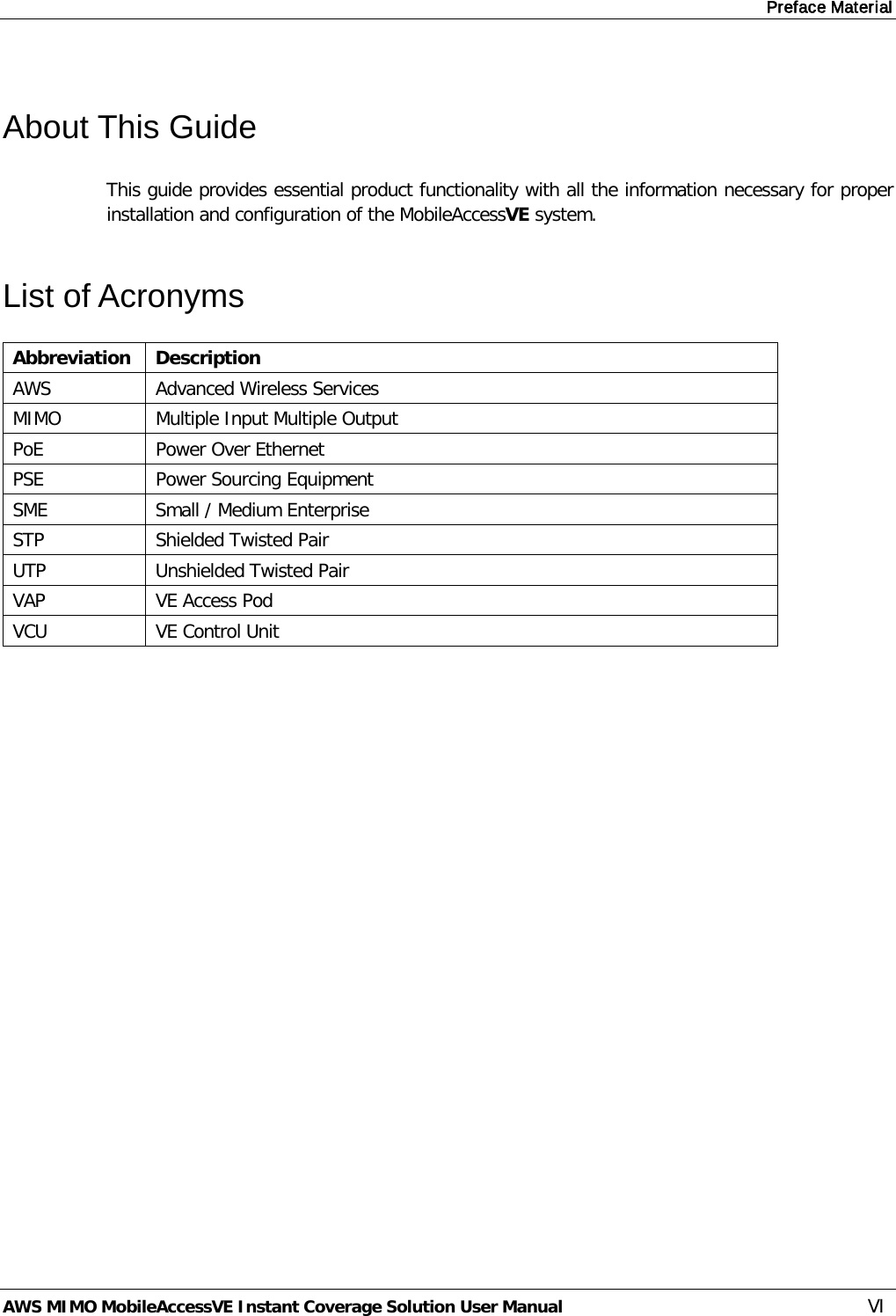
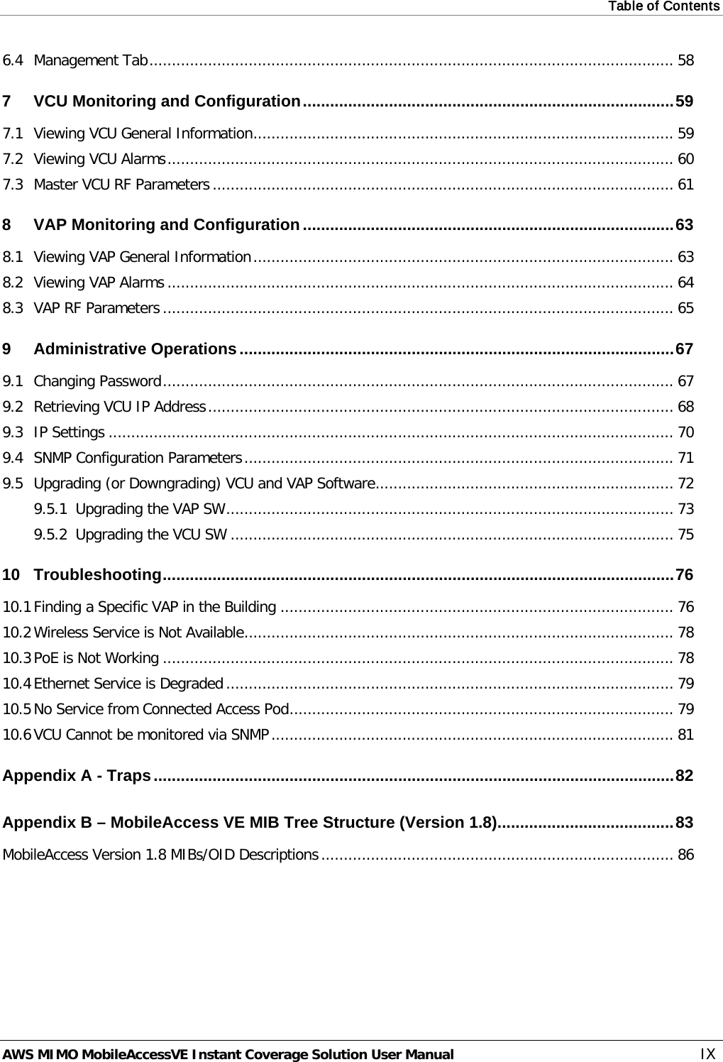
![VAP Installation and Provisioning AWS MIMO MobileAccessVE Instant Coverage Solution User Manual 44 5.4 Vertical Ceiling Mount VAP Installations Note: The VAP and required RJ-45 cable are supplied in the provided VE AWS VAP kit (See 5.2.1). The Vertical installation procedure varies depending on the type of ceiling: • Lowered ceilings – See 5.4.2. • Concrete/Wood ceilings – See 5.4.3. 5.4.1 VAP Kit Contents Please verify that the VAP Ceiling Mount Installation kit (P/N AK-VAP-CEILING-MT-V) includes the items listed below. Table 12: Vertical Mount VAP Kit Kit Items Description UNIT Mounting Brackets A) Ceiling Bracket B) Locke Bracket “Twist on” Track Light Clip assembly A) Track light Track Light Clip B) Screw, Bolt and Washer (3) Screw, Flat Head, 100', 4/40 x 1/4 [NEROSTA] Used for assembling brackets together (4) Self Screw,3dim L=8 ,Flat HD 90', PHILIPS, [steel zinc] Used to secure bracket assembly to VAP A B A B](https://usermanual.wiki/Corning-Optical-Communication-Wireless/VEAWSM/User-Guide-1433779-Page-53.png)