D Link SL6740BC2 Wireless VDSL2 4-port Ethernet Router User Manual DSL 6740B C2 QIG v1 00 EN x
D Link Corporation Wireless VDSL2 4-port Ethernet Router DSL 6740B C2 QIG v1 00 EN x
D Link >
user manual
Before You Begin
Make sure you have all the necessary information and equipment on hand before beginning the
installation.
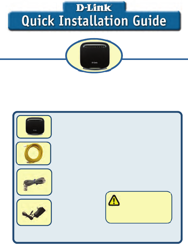
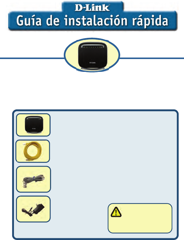
Check Your Package Contents
If any of the items above are missing, please contact your reseller.
DSL-6740B Wireless ADSL Router
Ethernet Cable (Cat 5 UTP)
Telephone cable
Power Adapter
Using a powersupply
with a different voltage rating
will damage and void the
warranty for this product.
This product can be set up using any
current web browser, i.e., Internet
Explorer 6x or Netscape Navigator 7x.
DSL-6740B
Wireless 11N VDSL Router
2
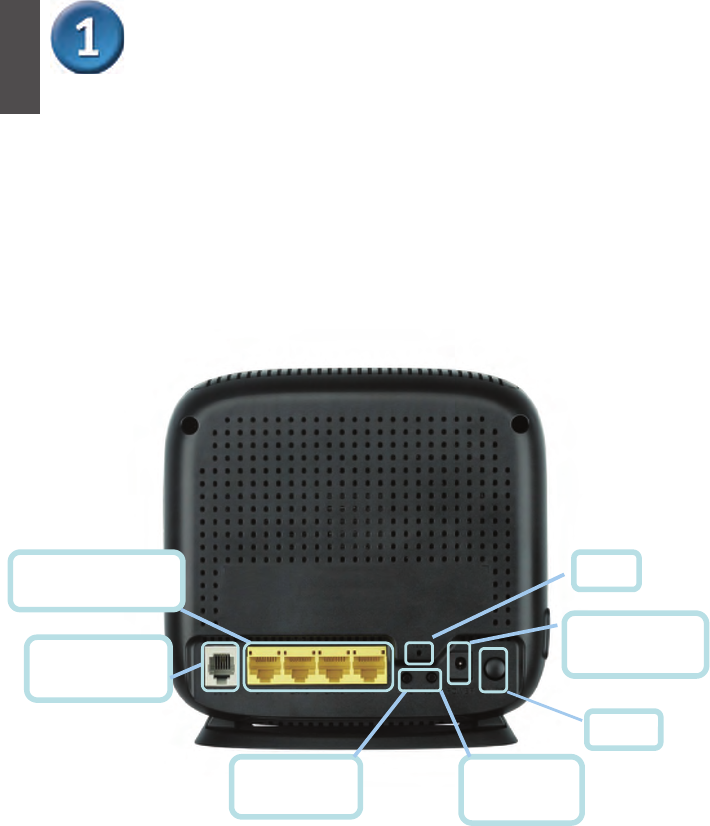
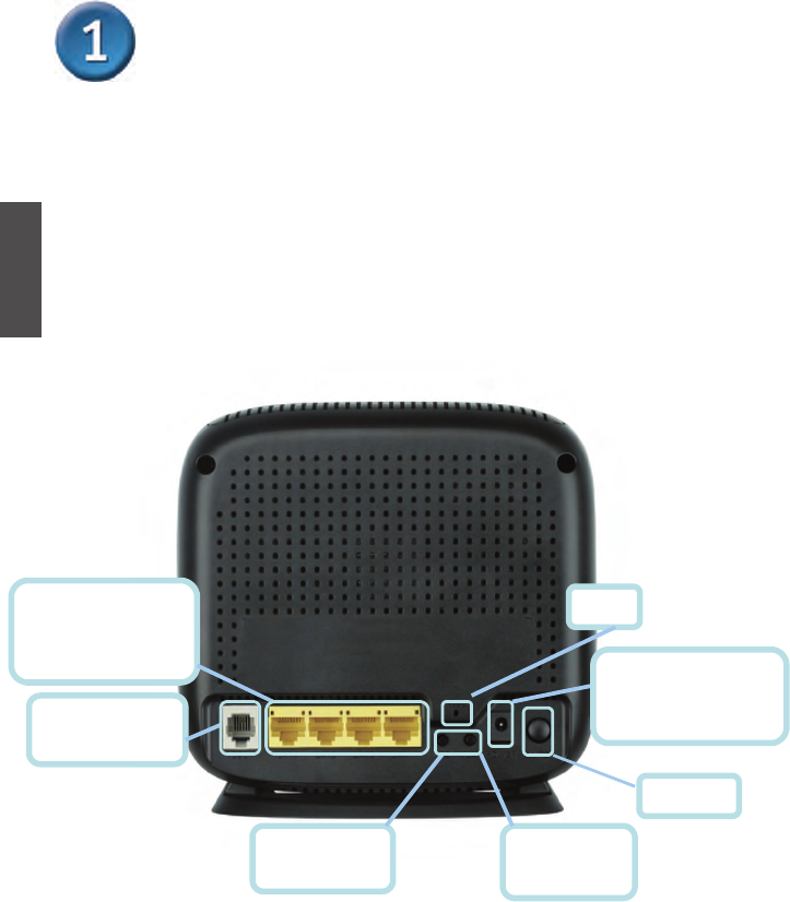
Connecting the Router to Your Computer
A. First, connect the power adapter to the receptor at the back panel of the
DSL-6740B and then plug the other end of the power adapter to a wall outlet or
power strip. The Power LED will turn on to indicate proper operation.
B. Insert one end of the cable into any Ethernet port on the back panel of the
DSL-6740B and the other end of the cable to an Ethernet Adapter or available Ethernet
port on your computer.
C. Insert one end of the telephone cable into the ADSL port on the back panel. Connect
the other end of the cable to the telephone wall outlet or low pass filter device that is
connected to the telephone wall outlet.
Ethernet Ports
Connect to Ethernet cable
Switch
PowerInput
Connect to power
WLAN button
Connect to STA
WPS button
Connect to WPS
DSL Port
Connect to ADSL
Reset
ENGLISH
3
Configuring the Router
To use your Web browser to access the web pages used to set up the Router, your computer
must be configured to “Obtain an IP address automatically,” that is, you must change the IP
network settings of your computer so that it is a DHCP Client. If you are using Windows XP
and do not know how to change your network settings, skip ahead to Appendix A and read the
instructions provided. You may also read the User Manual for instructions on changing IP
settings for computers running Windows operating systems.
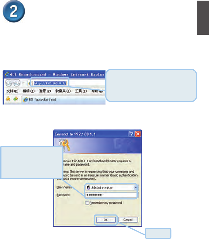
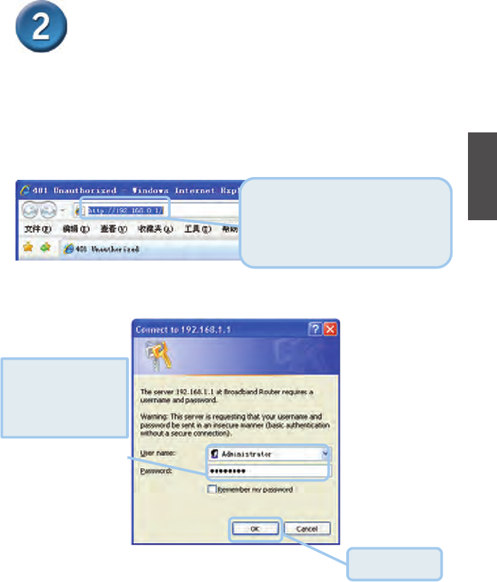
The logon pop-up screen will appear.
Open your Web browser and type
“http://192.168.0.1” into the URL address
box. Then press the Enter or Return
key.
The login dialog appears.
Type“
$GPLQLVWUDWRU
” for the
User Name and
“soporteETB2006” in the
Password field.
Click OK.
ENGLISH
4
Configuring the Router (continued)
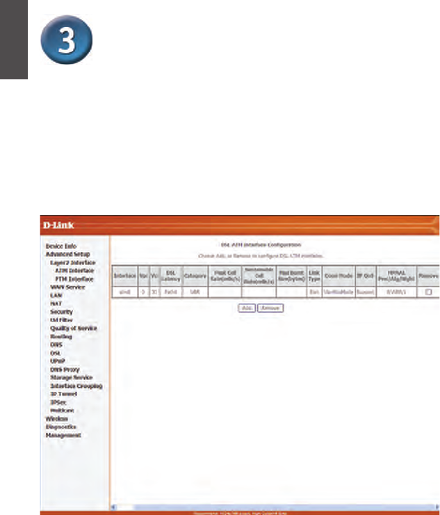
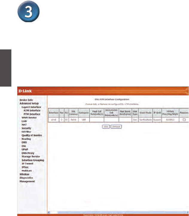
After loginin to the DSL router, if no PVC is configured previously and no default settings
exists, the Quick Setup webpage appears, which contains some basic configuration that is
needed by VPI/VCI.
z ATM Interface Configuration
Choose Advanced Setup > Layer2 Interface, and the following page appears, so you can
add or remove the ATMVPI/VCI and related configurations.
ENGLISH
5
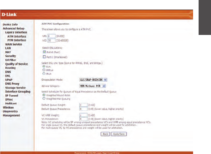
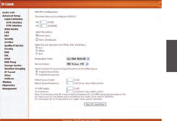
z ATM PVC Configuration
ENGLISH
6
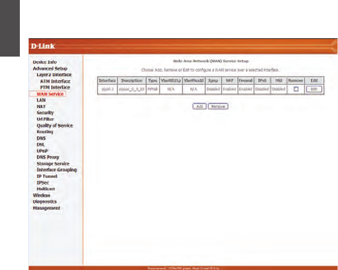
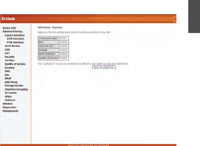
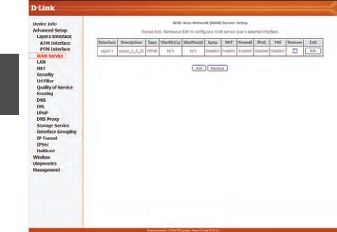
z WAN Service
Choose Advanced Setup >WAN Service, and the following page appears, so you can
add/remove/Edit the WAN interface.
Click Add
tocreate WAN service interface configuration; Click Edit to modify WAN service.
According to the page context, choose the right item and click Next, Back step by step to
configure WAN service.
ENGLISH
7
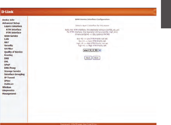
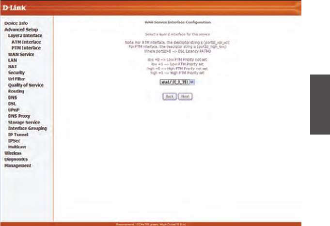
When creating a WAN service, you can see the following page:
Here, you can select ATM interface which you configured before.
ENGLISH
8
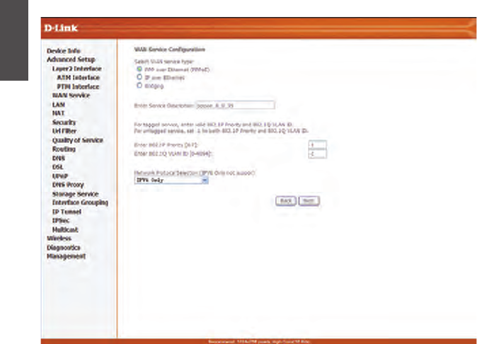
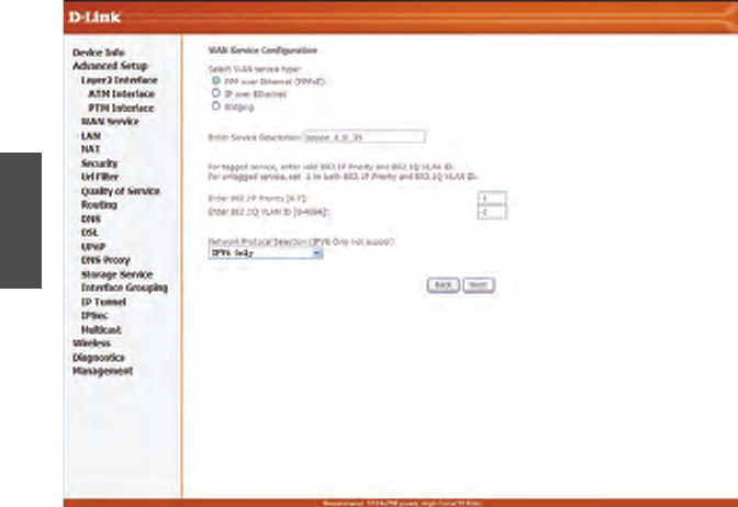
For “EoA” type of ATM interface, you can create PPPoE/IPoE/Bridge WAN service (as below):
ENGLISH
9
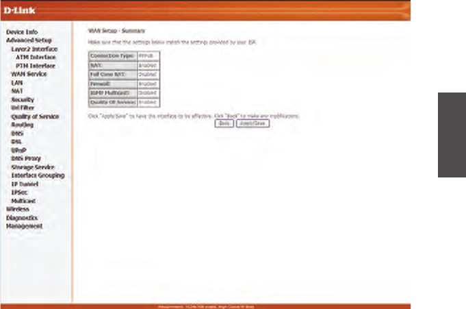
At last, click Apply/Save to save the modification.
ENGLISH
10
Configuring the Router (continued)
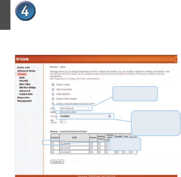
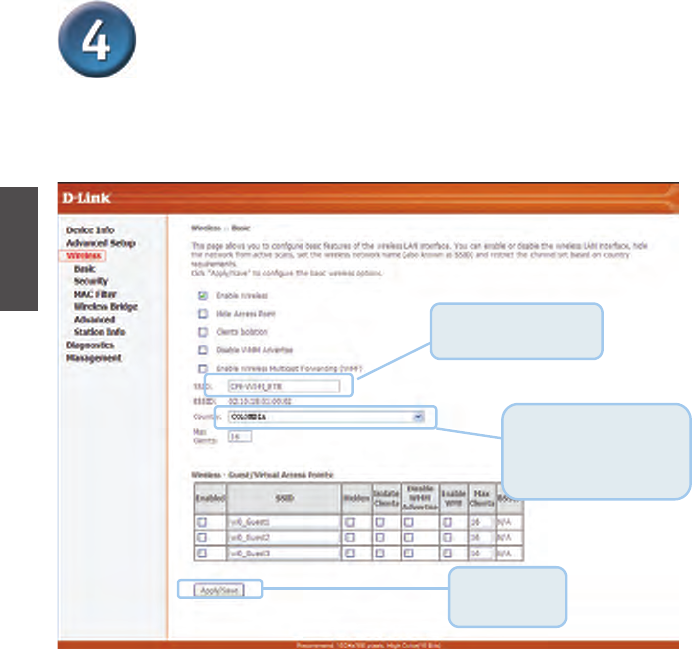
Wireless LAN Configuration
You can enable or disable the wireless LAN interface, hide the network from active scans,
set the wireless network name (also known as SSID) and restrict the channel set based on
country requirements.
Enter the SSID for the
Wireless LAN
The channel will adjust
according to nations to adapt
to each nation's
frequency provision.
Following is a description of the different options:
z Enable Wireless: If you want to make wireless be available, you have to check this
box first. Otherwise, the Hide Access Point SSID, Country, Enable Wireless Guest
Network, and Guest SSID box will not be displayed.
z Hide Access Point: Check this box if you want to hide any access point for your
router, so a station cannot obtain the SSID through passive scanning.
Click Apply / Save to save the basic wireless options and make the modification effect.
Click
Save/A
pp
l
y
ENGLISH
11
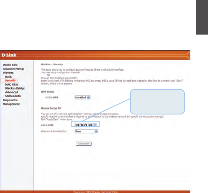
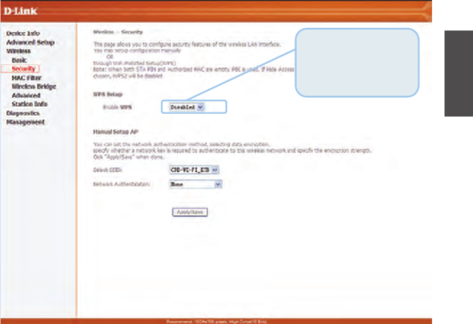
Wireless Security Configuration
DSL-6740B is equipped with WPA/WPA2 (Wi-Fi Protected Access), the latest security standard. It also
supports the legacy security standard, WEP (Wired Equivalent Privacy). By default, wireless security is
disabled and authentication is open. Before enabling the security, consider your network size, complexity,
and existing authentication infrastructure and then determine which solution applies to it.
z Select SSID: Select the wireless LAN of SSID to configure security features.
z Network Authentication: Select the authentication mode for the selected wireless LAN of SSID. Please
refer to the manual for more details of description.
Click Apply /Save to save the wireless security options and make the modification effect.
Select the wireless
LAN of SSID to
configure security
ft
ENGLISH
12
Appendix
For additional settings or information, refer to the Advanced, Tools, or Status tabs on the Web
Management interface; or to the manual located on the CD-ROM.
Configuring IP Settings in Windows XP
Use the following steps to configure a computer running Windows XP to be a DHCP client.
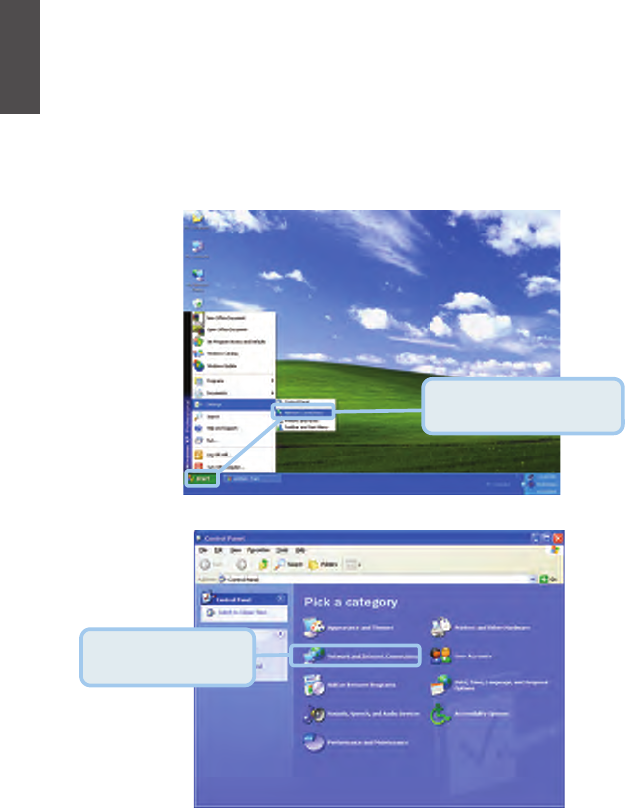
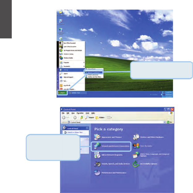
1. From the Start menu on your desktop, go to Control Panel.
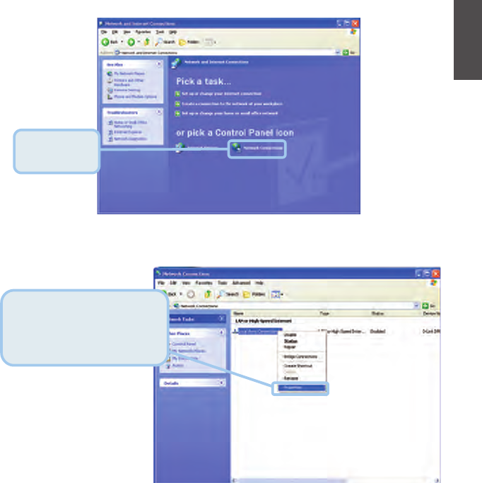
2. In the Control Panel window, click Network and Internet Connections.
Click Network and
Internet Connections.
From the Start menu, go to
Control Panel.
ENGLISH
13
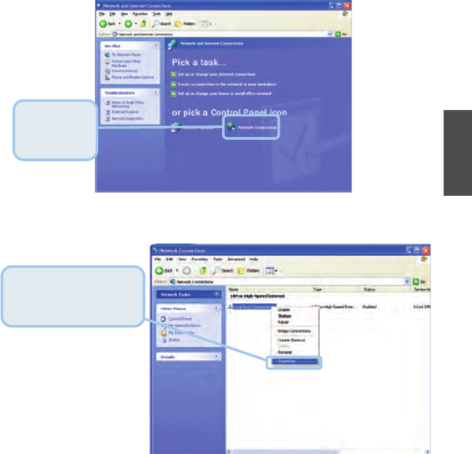
3. In the Network and Internet Connections window, click Network Connections.
4. In the Network Connections window, right-click on Local Area Connection, then click
Properties.
Right-click on the Local Area
Connection icon and select the
Properties option from the
pull-down menu.
Click Network
Connections.
ENGLISH
14
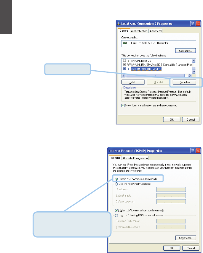
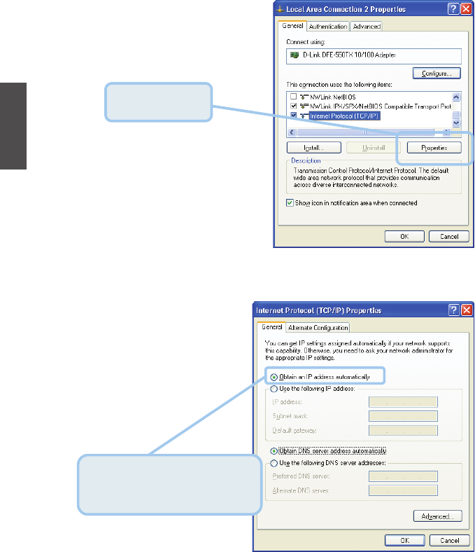
5. In the General tab of the Local Area Connection Properties window, highlight Internet
Protocol (TCP/IP) under “This connection uses the following items:” by clicking on it
once. Click on the Properties button.
6. Select “Obtain an IP address automatically” by clicking once in the circle. Click the OK
button.
Your computer is now ready to use the Router’s DHCP server.
Click Properties.
Select Obtain an IP address
automatically in the Internet
Protocol (TCP/IP) Properties window
ENGLISH
GUÍA DE INSTALACIÓN RÁPIDA
Antes de comenzar
Asegúrese de que usted cuenta con toda la información necesaria y el equipo a la mano antes
de comenzar la instalación
Compruebe el contenido del empaquete
Si alguno de los componentes anteriores no se encuentra, por favor contáctese con su
distribuidor.
Router ADSL Wireless DSL-6740B
Cable Ethernet (Cat 5 UTP)
Cable de teléfono
Adaptador de energía
Este producto puede configurarse
usando cualquier navegador web actual,
es decir, Internet Explorer o Netscape
Navigator 6x 7x.
DSL-6740B
Router VDSL Wireless 11N
Una fuente de
alimentación
con distinto voltaje puede ser
perjudicial y anular la garantía
Conexión del Router al Computador
A. En primer lugar, conecte el adaptador de alimentación al receptor ubicado en el panel
trasero del DSL-6740B y luego conecte el otro extremo del adaptador de alimentación
a una toma de corriente o regleta. El LED se encenderá para indicar un
funcionamiento correcto.
B. Introduzca un extremo del cable a un puerto Ethernet del panel trasero del DSL-6740B
y el otro extremo del cable en un adaptador Ethernet o puerto Ethernet disponible en
su computador.
C. Inserte un extremo del cable telefónico en el puerto ADSL ubicado en el panel
posterior. Conecte el otro extremo del cable al conector de teléfono de la pared o el
dispositivo de filtro de paso bajo que está conectado a la toma de corriente de pared.
Puertos Ethernet
Conectar con un cable
Ethernet
Switch
Botón WLAN
Conecta a STA
Botón WPS
Conecta a WPS
Puerto DSL
Conectar a ADSL
Reset
Entrada de energía
eléctrica
Conecta a la energía
ESPAÑOL
16
Abra su navegador Web y escriba
"http://192.168.0.1" en la barra de
direcciones URL. A continuación, pulse la
tecla Enter o Return.
La ventana inicio de sesión aparecerá.
Escriba "Administrador"
para el User name: y
"soporteETB2006" en el
campo Password:
Haga Clic en OK.
ESPAÑOL
17
Configurar el Router
Para utilizar el navegador web y acceder a las páginas web que se utilizan para configurar el
router, su equipo debe estar configurado para "Obtener una dirección IP automáticamente", es
decir, debe cambiar la configuración de red IP de su computador para que sea un Cliente de
servidor DHCP. Si utiliza Windows XP y no sabe cómo cambiar la configuración de red, vaya al
Apéndice A y lea las instrucciones proporcionadas. También puede leer el Manual del Usuario
para obtener instrucciones sobre cómo cambiar los parámetros IP en computadores con
sistemas operativos Windows.
La ventana inicio de sesión aparecerá.
ESPAÑOL
18
Configurar el Router (continuación)
Después de iniciar su sesión en el router DSL, si no se ha configurado previamente PVC y no
existen ajustes por defecto, la página web de configuración rápida aparecerá, la cual contiene
una configuración básica necesaria para VPI / VCI.
z Configuración de la interfaz ATM
Seleccione Configuración avanzada> Interface Layer 2, aparece la siguiente página, para
que pueda agregar o quitar la ATMVPI / VCI y las configuraciones relacionadas.
ESPAÑOL
19
z Configuración ATM PVC
ESPAÑOL
20
z Servicio WAN
Seleccione Configuración avanzada> Servicio WAN, y aparece la siguiente página, para que
pueda añadir / eliminar / editar la interfaz WAN.
Haga clic en Add para crear una configuración de interfaz de servicios WAN; Haga clic en Edit
para modificar el servicio WAN. De acuerdo con el contexto de la página, seleccione el
elemento de la derecha y haga clic en Next, Back, paso a paso para configurar el servicio
WAN.
ESPAÑOL
21
Al crear un servicio WAN, se puede ver la siguiente página:
Aquí, usted puede seleccionar la interfaz ATM que se ha configurado antes.
ESPAÑOL
22
Para el tipo de interfaz ATM "EoA", puede crear servicio WAN: PPPoE / IPoE / Bridging
ESPAÑOL
23
Por último, haga clic en Apply/Save para guardar la modificación.
Configurar el Router (continuación)
Configuración Wireless LAN
Puede activar o desactivar la interfaz LAN inalámbrica, ocultar las búsquedas activas de red,
establecer el nombre de red inalámbrica (también conocido como SSID) y restringir el canal
ajustado sobre la base de los requisitos del país.
Ingrese el SSID para la
LAN inalámbrica
El canal se ajustará de
acuerdo a los países para
adaptarse a cada disposición
de frecuencia
A continuación se presenta una descripción de las diferentes opciones:
• Habilitar Wireless: Si usted desea habilitar la red inalámbrica, debe activar esta
primera casilla. De lo contrario, no se mostrarán las opciones Hide Access Point SSID, Country, Enable
Wireless Guest Network, and Guest SSID.
• Esconder (Hide)Access Point: Marque esta casilla si desea ocultar cualquier punto de acceso
de su router, así una estación no podrá obtener el SSID a través del escaneo pasivo.
Haga clic en Apply/Save para guardar las opciones inalámbricas básicas y que las modificaciones se
hagan efectivas.
Clic en
A
pp
l
y
/Save
ESPAÑOL
24
Seleccione SSID de
la red LAN inalámbrica
para configurar la
seguridad
ESPAÑOL
25
Configuración de Seguridad Inalámbrica
DSL-6740B está equipado con WPA/WPA2 (Wi-Fi Protected Access), el estándar de seguridad más reciente.
También es compatible con el estándar de seguridad heredado, WEP (Wired Equivalent Privacy). De forma
predeterminada, la seguridad inalámbrica está desactivada y la autenticación está abierta. Antes de habilitar
la seguridad, tenga en cuenta el tamaño de su red, la complejidad y la infraestructura de autenticación
existente y luego determine qué solución se aplica a ella.
• Seleccione SSID: Seleccione SSID de de la red inalámbrica para configurar las funciones de
seguridad.
• Autenticación de red: seleccione el modo de autenticación para la LAN inalámbrica seleccionada.
Por favor, consulte el manual para obtener más detalles de descripción.
Haga clic en Apply/Save para guardar las opciones de seguridad inalámbrica y las modificaciones se hagan
efectivas.
Apéndice
Para información o parámetros adicionales, consulte las pestañas Avanzado, Herramientas, o
Estado en la interfaz de administración web, o consulte el manual que se incluye en el
CD-ROM.
Configuración de los parámetros IP en Windows XP
Utilice los siguientes pasos para configurar un computador con Windows XP para que sea un
cliente DHCP. En el menú Inicio, vaya a Panel de control.
1. En la ventana panel de control, haga clic en Conexiones de redes e Internet.
Haga Clic en
Conexiones de red e
Internet
En el menú Inicio (Start),
vaya al Panel de control.
ESPAÑOL
26
Haga clic en
Conexiones de
Red.
Clic derecho en Red de
Área Local, luego clic en
Propiedades.
ESPAÑOL
27
2. En la ventana Conexiones de redes e Internet, haga clic en Conexiones de Red.
3. En la ventana Conexiones de Red, Clic derecho en Red de Área Local, luego clic en
Propiedades.
Haga Clic en
Propiedades.
Seleccione "Obtener una dirección IP
automáticamente" en la ventana de
propiedades
ESPAÑOL
28
4. En la pestaña General de la ventana Propiedades de conexión de área local, seleccione
Protocolo de Internet (TCP / IP) "Esta conexión utiliza los siguientes elementos:"
haciendo clic en él una vez. Haga clic en el botón Propiedades.
5. Seleccione "Obtener una dirección IP automáticamente" haciendo clic una vez en el
círculo. Haga clic en el botón Aceptar.
El equipo está ahora listo para usar el servidor DHCP del router.
Suporte técnico
Usted puede encontrar actualizaciones de softwares o rmwares y documentación para usuarios a
través de nuestro sitio www.dlinkla.com
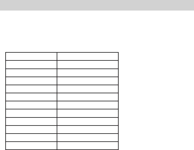
SOPORTE TÉCNICO PARA USUARIOS EN LATINO AMERICA
Soporte técnico a través de los siguientes teléfonos de D-Link
PAIS NUMERO
Argentina 0800 - 12235465
Chile 800 260200
Colombia 01800 - 510070
Costa Rica 0800 - 0521478
Ecuador 1800 - 035465
El Salvador 800 - 6335
Guatemala 1800 - 8350255
México 01800 - 0626270
Panamá 011 008000525465
Perú 0800 - 00968
Venezuela 0800 - 1005767
Soporte Técnico de D-Link a través de Internet
Horario de atención Soporte Técnico en www.dlinkla.com
e-mail: soporte@dlinkla.com & consultas@dlinkla.com

NOTES
FCC INFORMATION
This equipment complies with CFR 47, Part 15.19 of the FCC rules. Operation of the equipment is subject to the
following conditions: (1) this device may not cause harmful interference, and (2) this device must accept any
interference received; including interference that may cause undesired operation.
THIS DEVICE MUST NOT BE CO-LOCATED OR OPERATING IN CONJUNCTION WITH ANY OTHER
ANTENNA OR TRANSMITTER
FCC - PART 68 This equipment complies with Part 68 of the FCC rules and the requirements adopted by the ACTA.
On the bottom of this equipment is a label that contains, among other information, a product identifier in the format
US:3P7DL01BDSL-6740 andREN is 0.12B for the test equipment. The REN is used to determine the number of devices
that may be connected to a telephone line. Excessive RENs on a telephone line may result in the devices not ringing in
response to an incoming call. n most but not all areas, the sum of RENs should not exceed five (5.0). To be certain of the
number of devices that may be connected to a line, as determined by the total RENs, contact the local telephone company.
For products approved after July 23, 2002, the REN for this product is part of the product identifier that has the format
US:AAAEQ##TXXXX. The digits represented by ## are the REN without a decimal point (e.g., 03 is a REN of 0.3).
For earlier products, the REN is separately shown on the label.It uses the following USOC jacks: RJ-45,RJ11.
A plug and jack used to connect this equipment to the premises wiring and telephone network must comply with the
applicable FCC Part 68 rules and requirements adopted by the ACTA. A compliant telephone cord and modular plug
is provided with this product. It is designed to be connected to a compatible modular jack that is also compliant.
See installation instructions for details. If this equipment, the Wireless VDSL2 4-port Ethernet Router ,causes harm to the
telephone network, the telephone company will notify you in advance that temporary discontinuance of service may be required.
But if advance notice isn’t practical, the telephone company will notify the customer as soon as possible. Also, you will be advised
of your right to file a complaint with the FCC if you believe it is necessary.The telephone company may make changes in its facilities,
equipment, operations or procedures that could affect the operation of the equipment. If this happens the telephone company will
provide advance notice in order for you to make necessary modifications to maintain uninterrupted service.
If trouble is experienced with this equipment, Wireless VDSL2 4-port Ethernet Router, for repair or warranty information.
please contact: D-Link USA Inc. 7 Phone : 14-885-6000 If the equipment is causing harm to the telephone network,
the telephone company may request that you disconnect the equipment until the problem is resolved.
If your home has specially wired alarm equipment connected to the telephone line, ensure the installation of this device.
does not disable your alarm equipment. If you have questions about what will disable alarm equipment, consult your telephone
company or qualified installer .Connection to party line service is subject to state tariffs. Contact the state public utility commission,
public service commission or corporation commission for information.Electrical Safety Advisory Telephone companies report that
electrical surges, typically lightning transients, are very destructive to customer terminal equipment connected to AC power sources.
This has been identified as a major nationwide problem. Therefore it is advised that this equipment be connected to AC power through
the use of a surge arrestor or similar protection device. Manufacturer’s Declaration of Conformance Warnings: This is a Class B
product. In a domestic environment this product may cause radio interference, in which case the user may be required to take
adequate measures. Adequate measures include increasing the physical distance between this product and other electrical devices.
Federal Communications Commission (FCC) Requirements, Part 15
This equipment has been tested and found to comply with the limits for a class B digital device, pursuant to part 15 of
the FCC Rules. These limits are designed to provide reasonable protection against harmful interference in a residential
installation.
This equipment generates, uses and can radiate radio frequency energy and, if not installed and used in accordance with
the instructions, may cause harmful interference to radio communications. However, there is no guarantee that
interference will not occur in a particular installation. If this equipment does cause harmful interference to radio or
television reception, which can be determined by turning the equipment off and on, the user is encouraged to try to
correct the interference by one or more of the following measures:
---Reorient or relocate the receiving antenna.
---Increase the separation between the equipment and receiver.
---Connect the equipment into an outlet on a circuit different from that to which the receiver is connected.
---Consult the dealer or an experienced radio/TV technician for help.
REGULATORY INFORMATION / DISCLAIMERS
Installation and use of this Wireless LAN device must be in strict accordance with the instructions included in the user
documentation provided with the product. Any changes or modifications (including the antennas) made to this device
that are not expressly approved by the manufacturer may void the user’s authority to operate the equipment. The manufacturer is
not responsible for any radio or television interference caused by unauthorized modification of this device, or the substitution of the
connecting cables and equipment other than manufacturer specified. It is the responsibility of the user to correct any interference caused
by such unauthorized modification, substitution or attachment. Manufacturer and its authorized resellers or distributors will assume no
liability for any damage or violation of government
CAUTION: To maintain compliance with FCC’s RF exposure guidelines, this equipment should be installed and
operated with minimum distance 20cm between the radiator and your body. Use on the supplied antenna. Unauthorized
antenna, modification, or attachments could damage the transmitter and may violate FCC regulations.
MPE Statement (Safety Information)
Your device contains a low power transmitter. When device is transmitted it sends out Radio Frequency (RF) signal.
SAFETY INFORMATION
In order to maintain compliance with the FCC RF exposure guidelines, this equipment should be installed and operated
with
minimum distance 20cm between the radiator and your body. Use only with supplied antenna. Unauthorized antenna,
modification,
or attachments could damage the transmitter and may violate FCC regulations.

NOTES

Ver. 1.00(ETB)
2013/01/28
EDTA0400021-GDL