DASAN Zhone Solutions 6519W1 ADSL2+ 4-PORT 802.11 N WiFi Router User Manual
Zhone Technologies, Inc. ADSL2+ 4-PORT 802.11 N WiFi Router
UserManual.wiki
>
DASAN Zhone Solutions
>
6519W1 User Manual
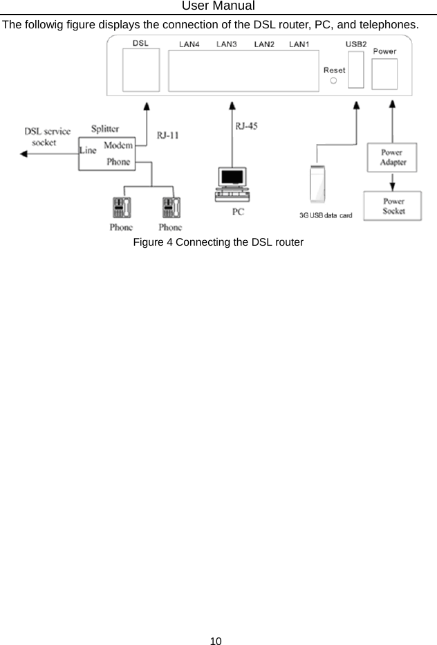
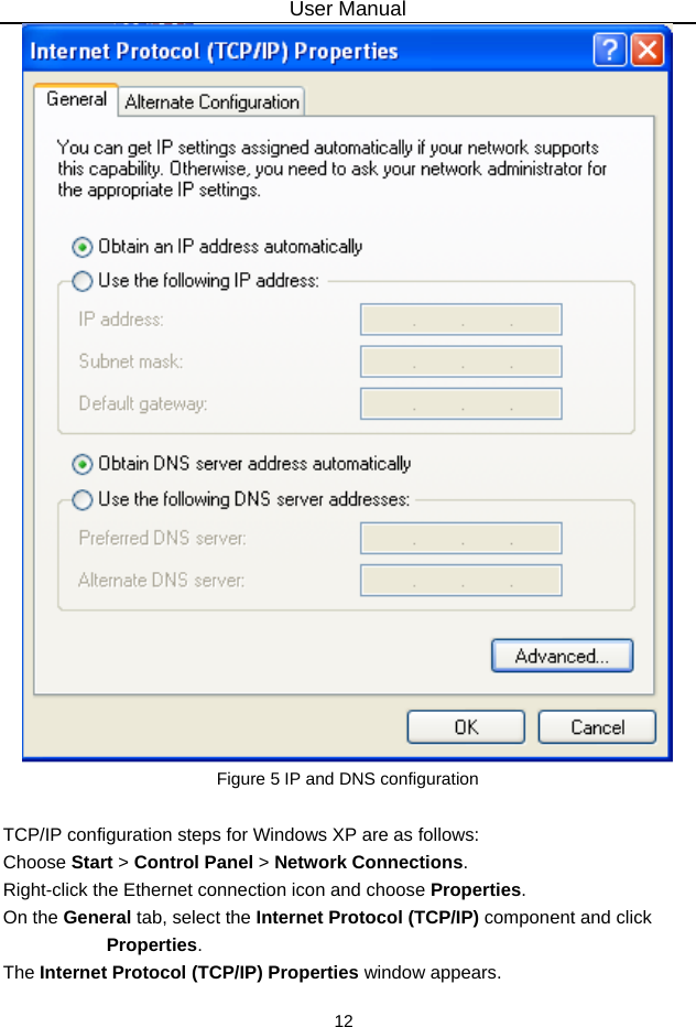
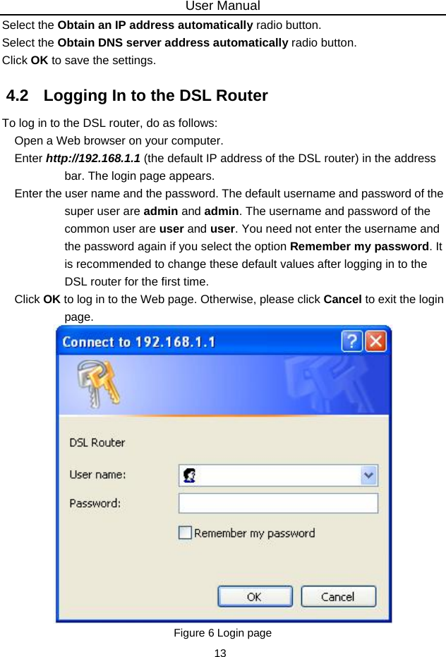
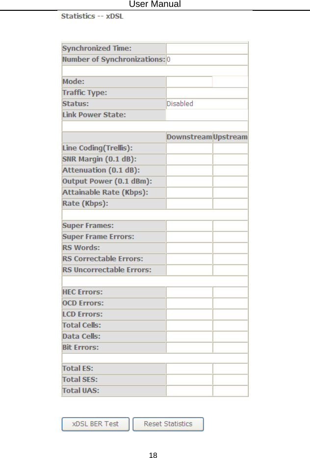
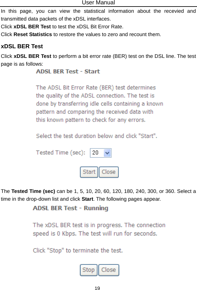
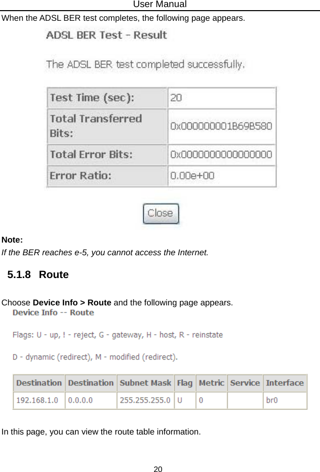
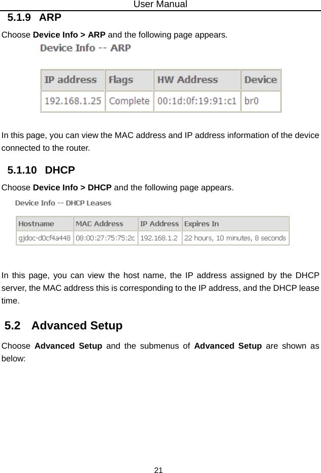
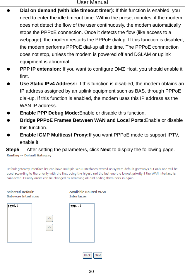
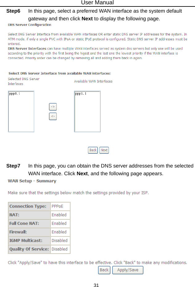
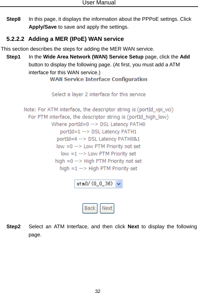
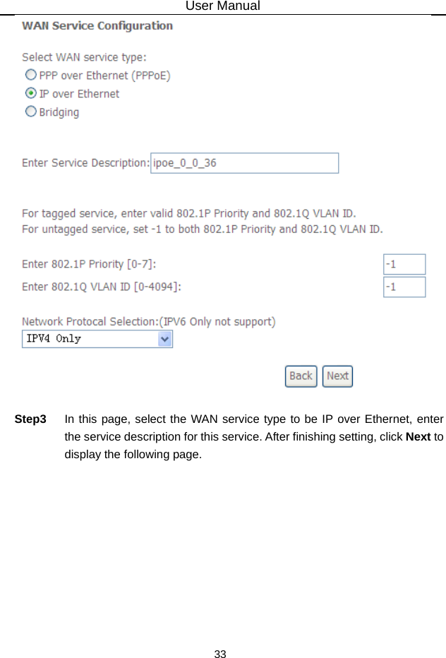
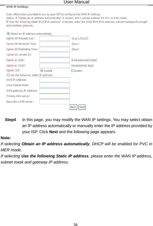
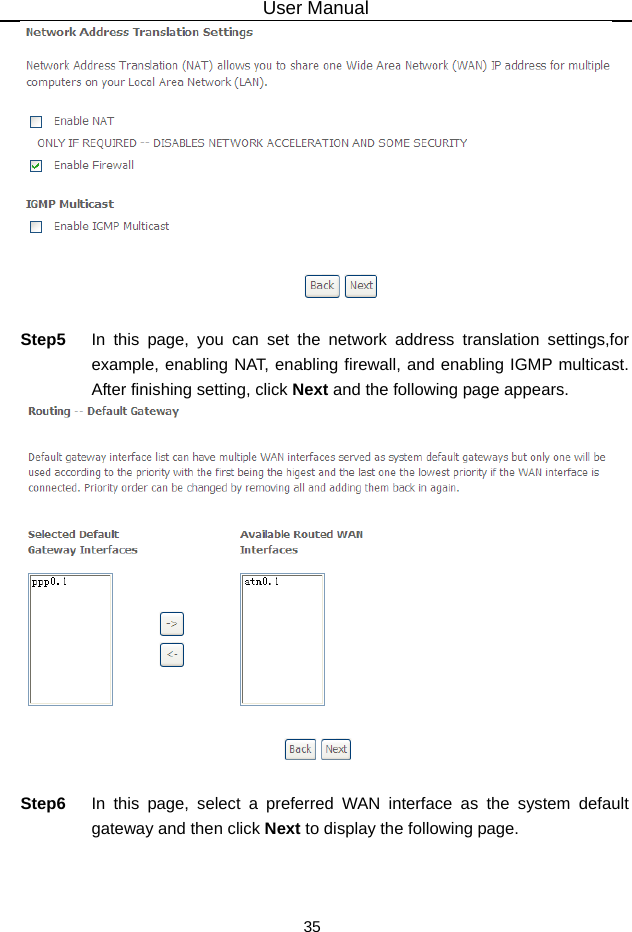
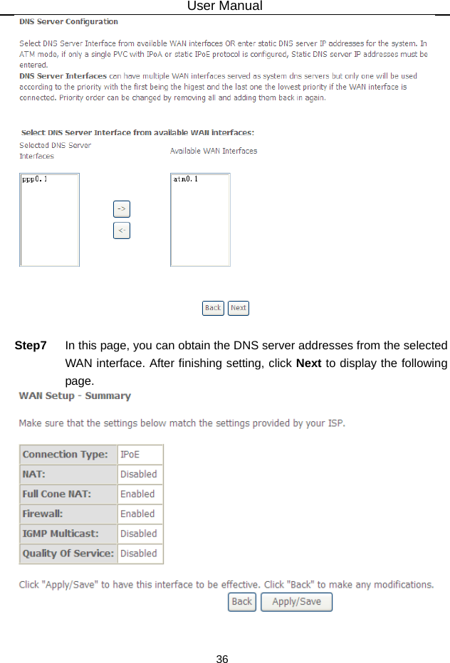
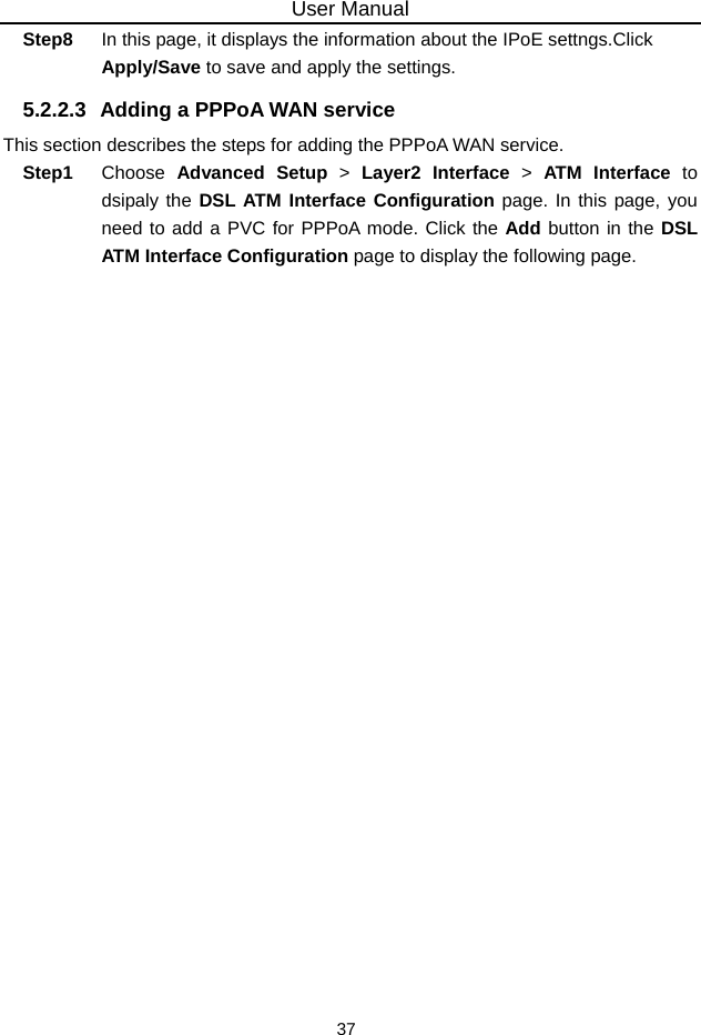
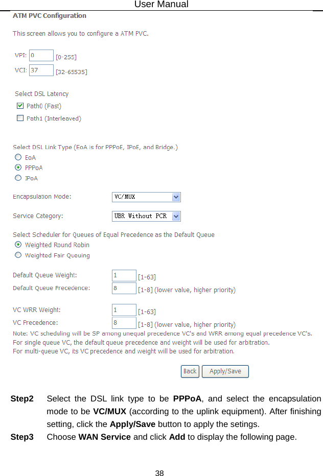
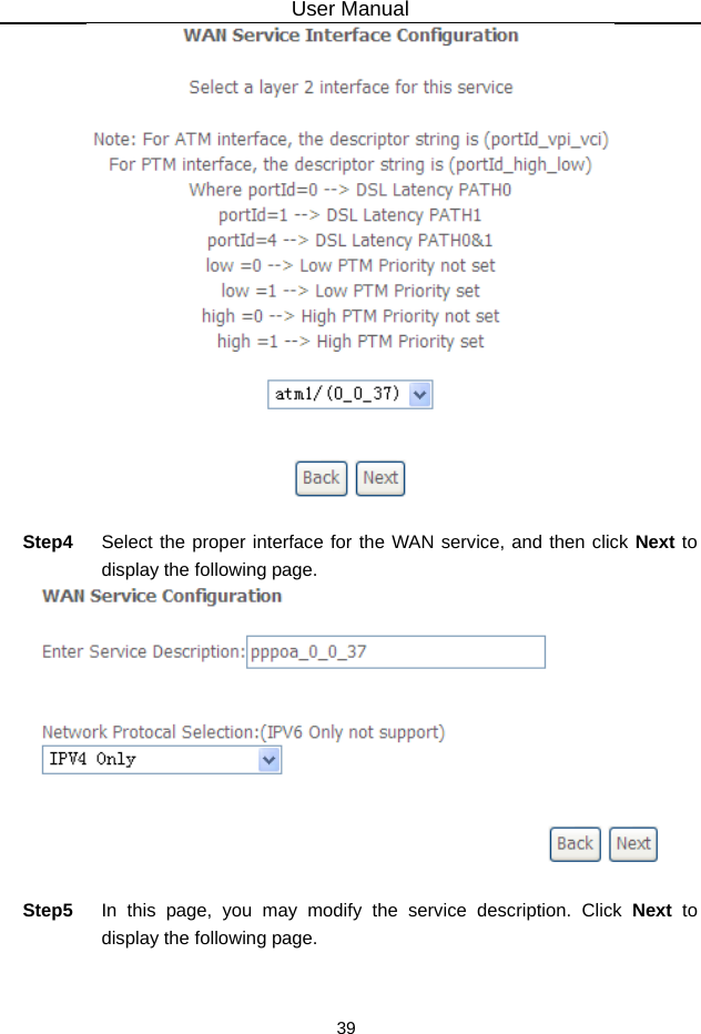
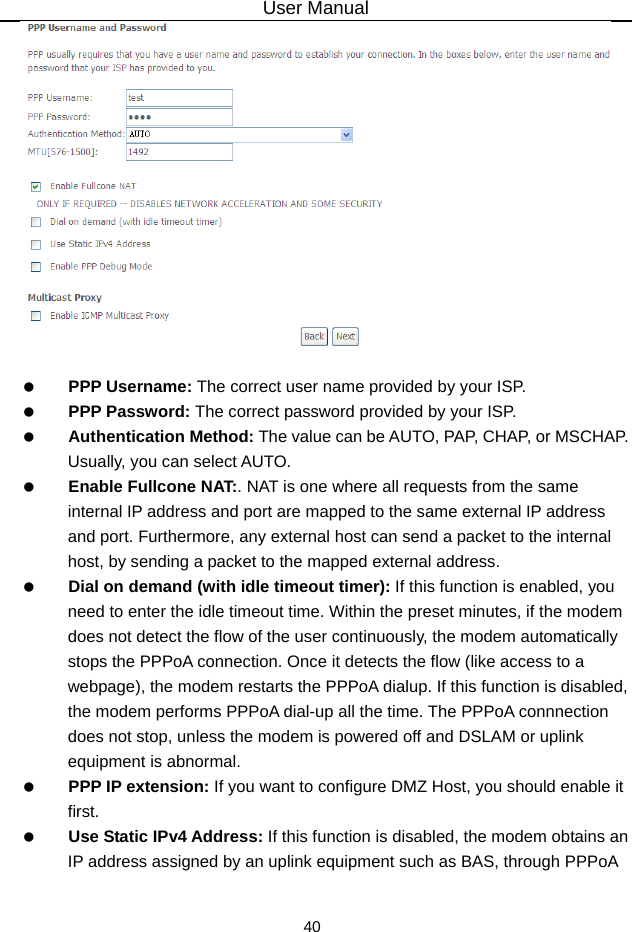
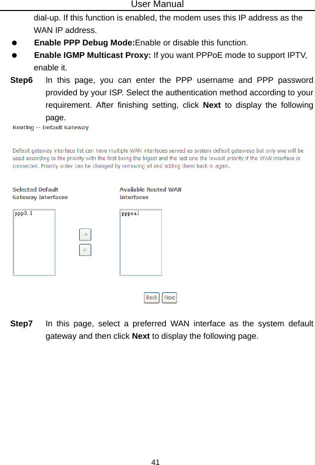
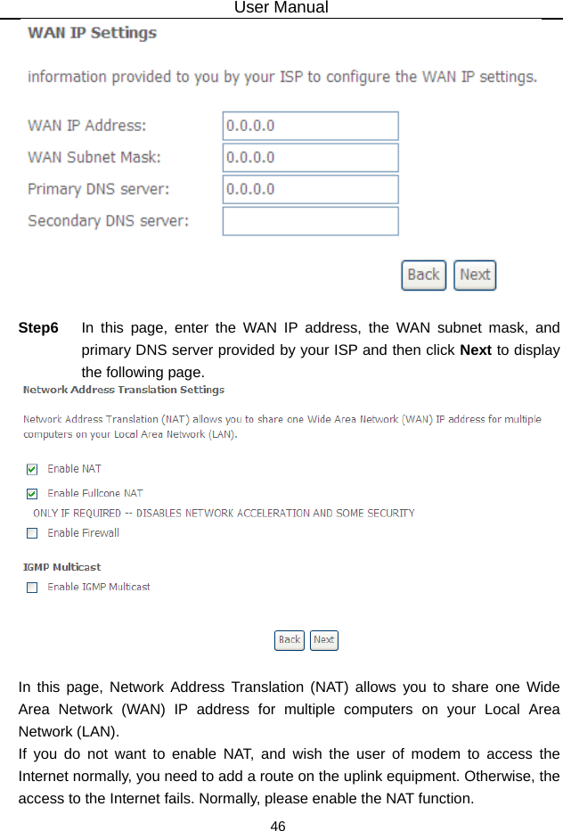
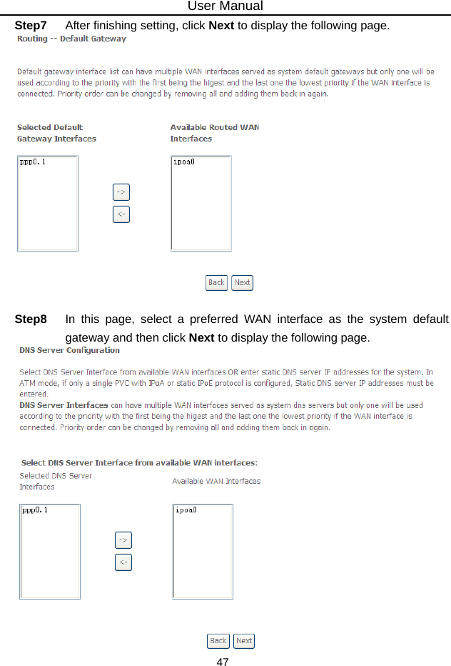
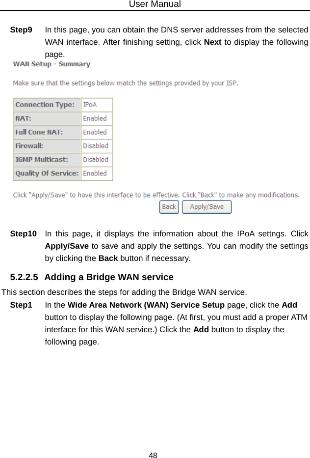
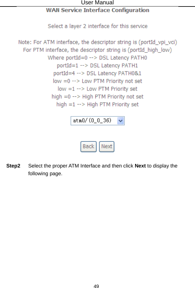
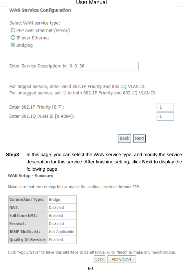
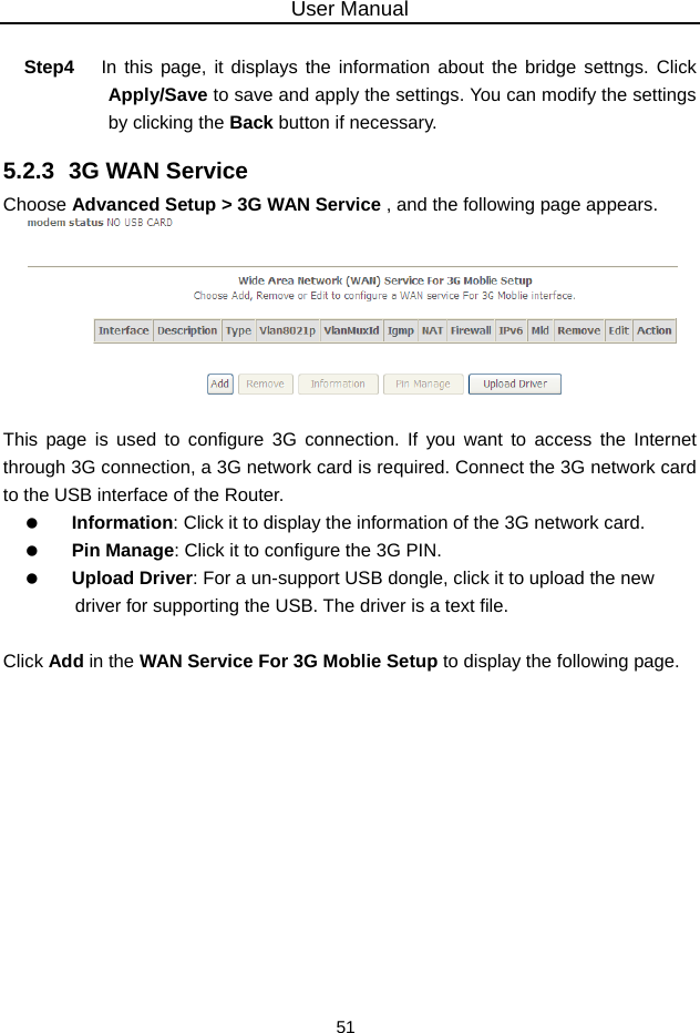
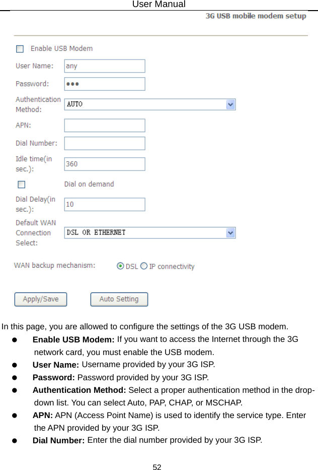
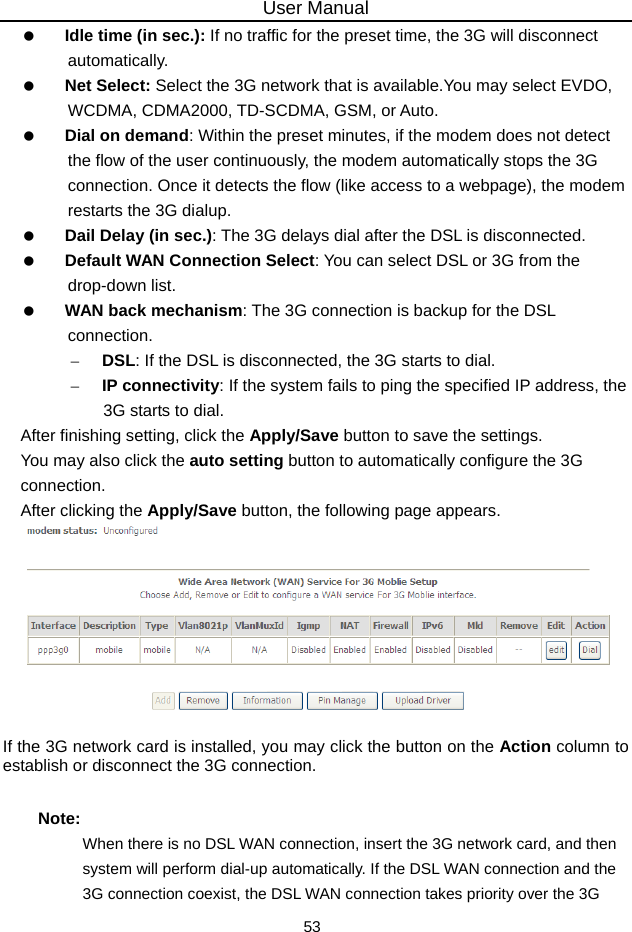
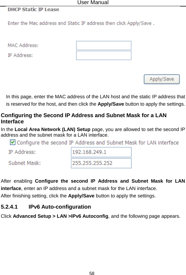
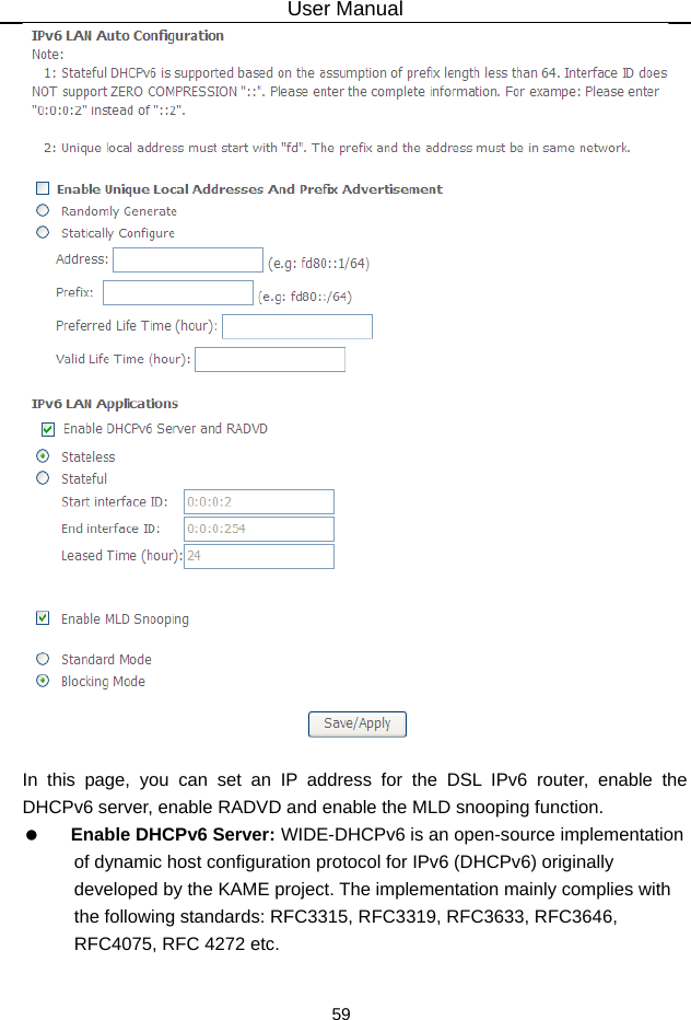
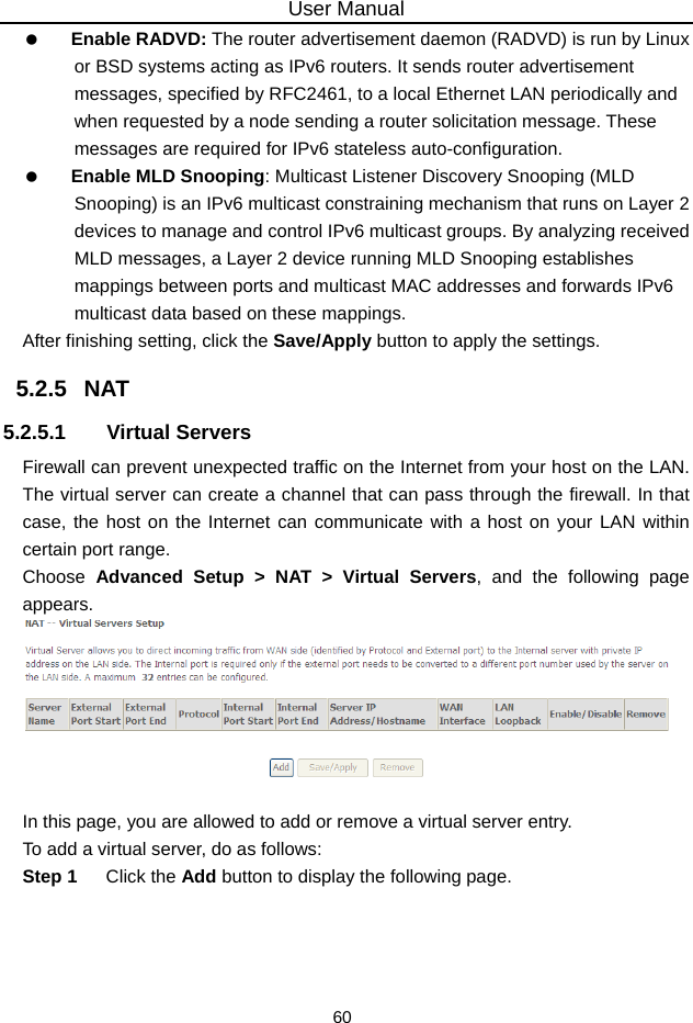
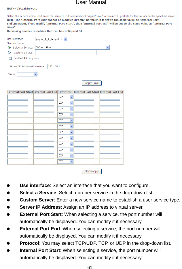
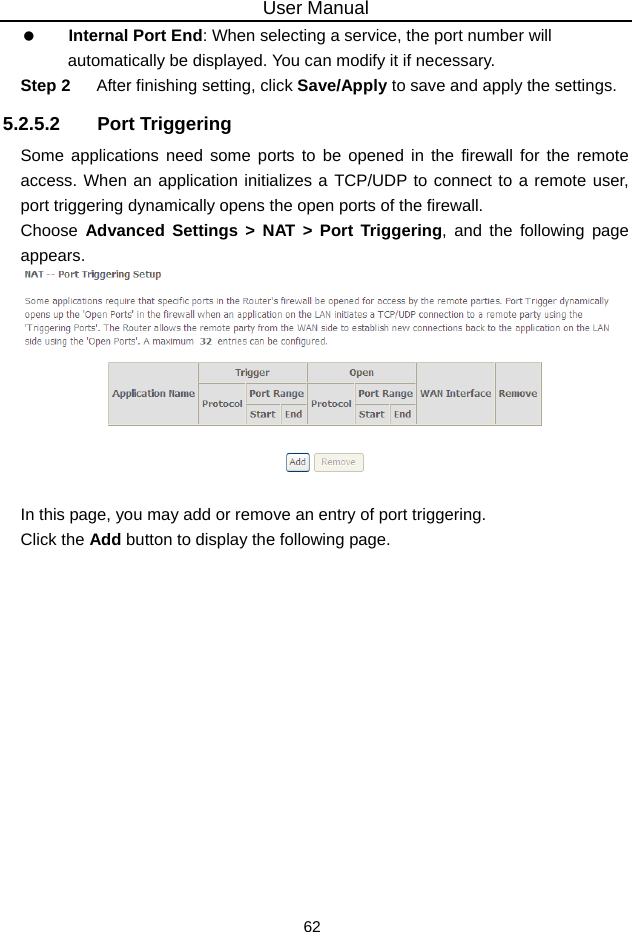
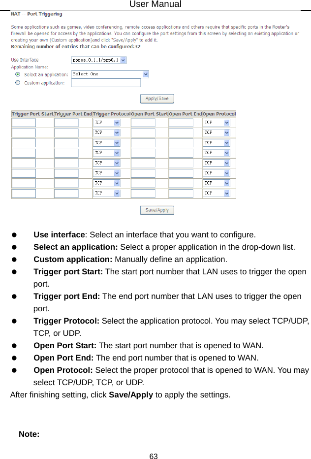
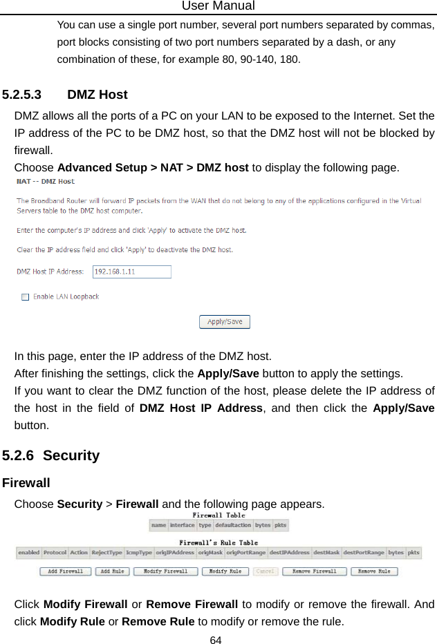
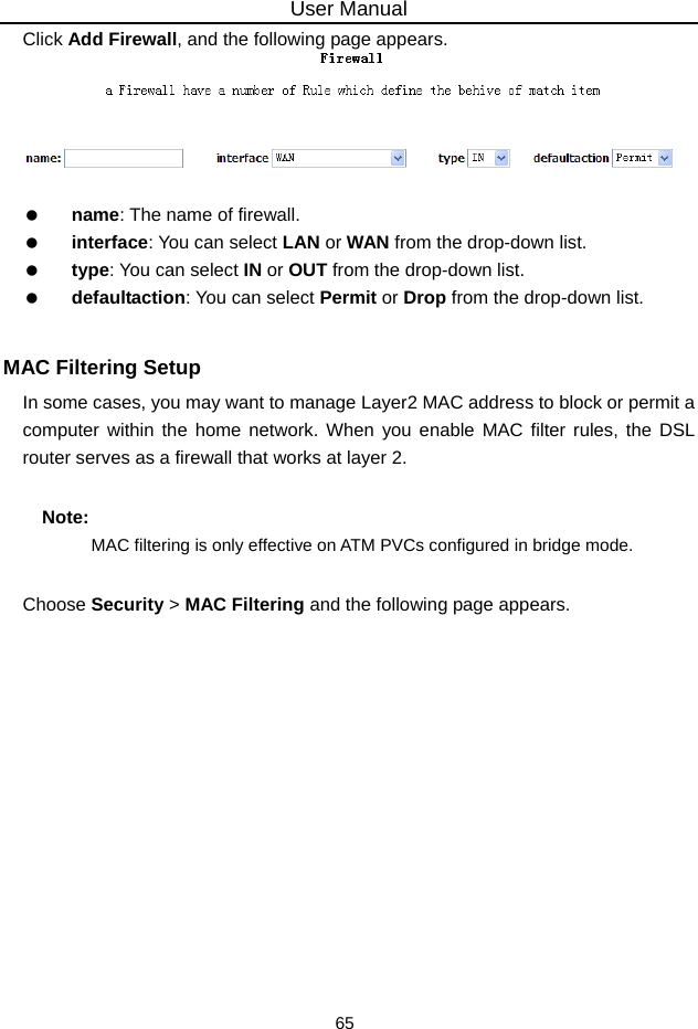
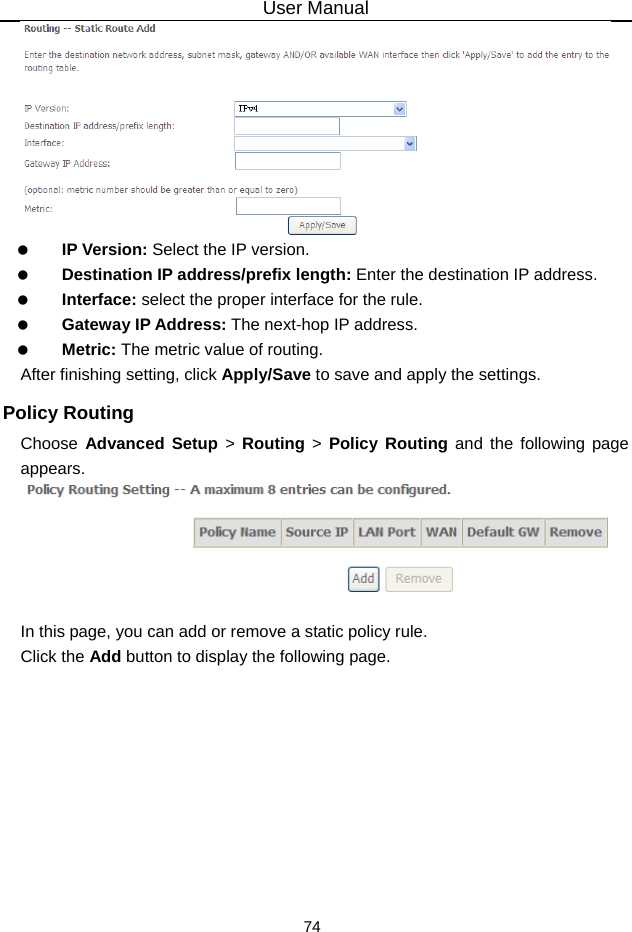
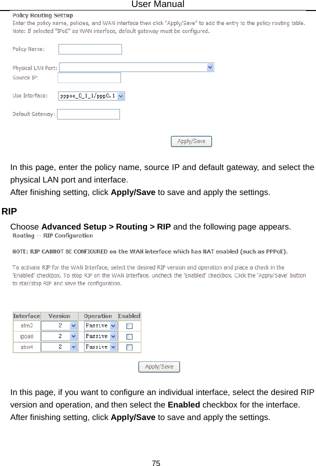
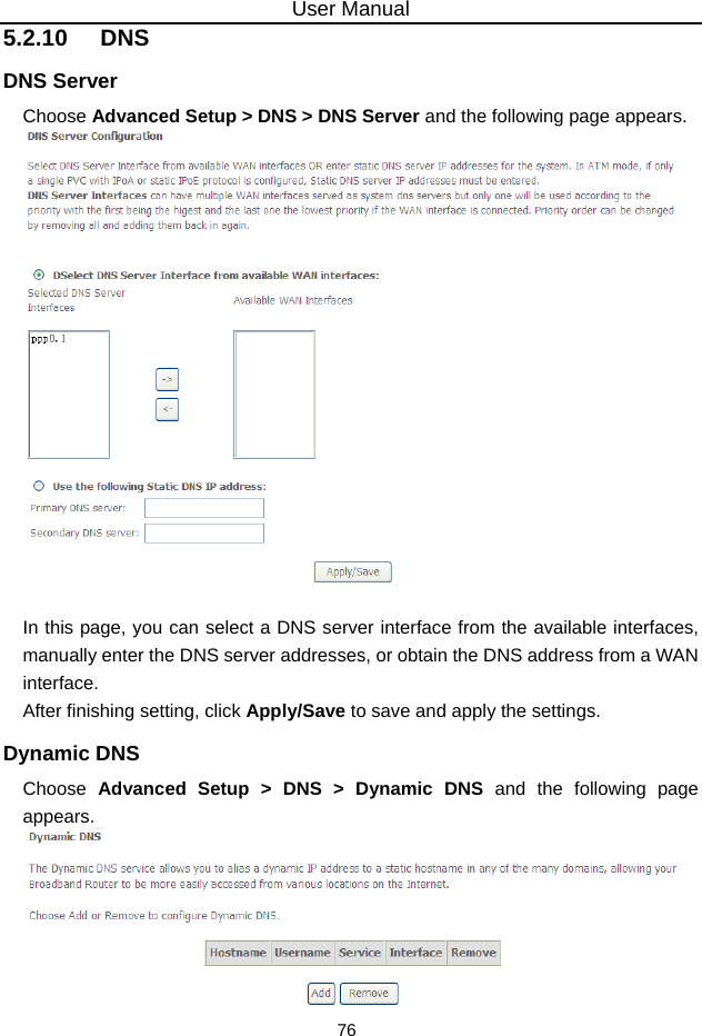
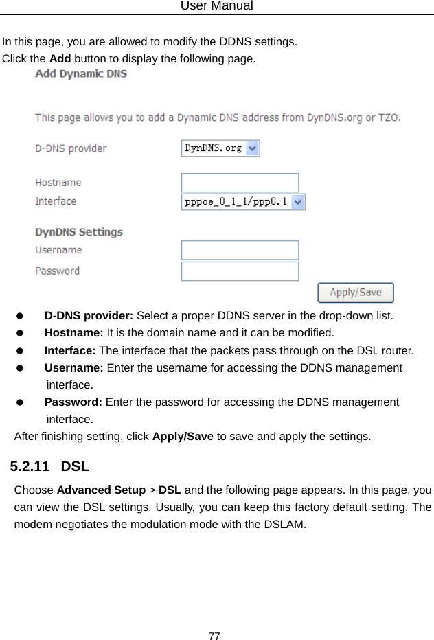
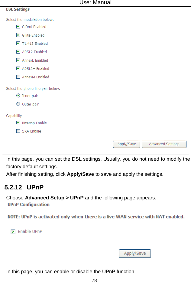
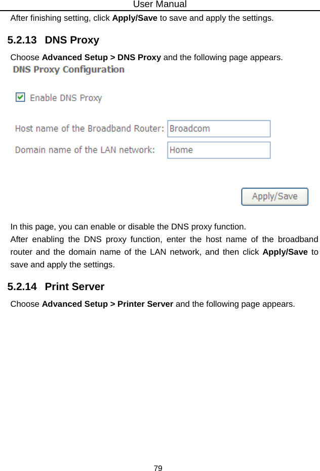
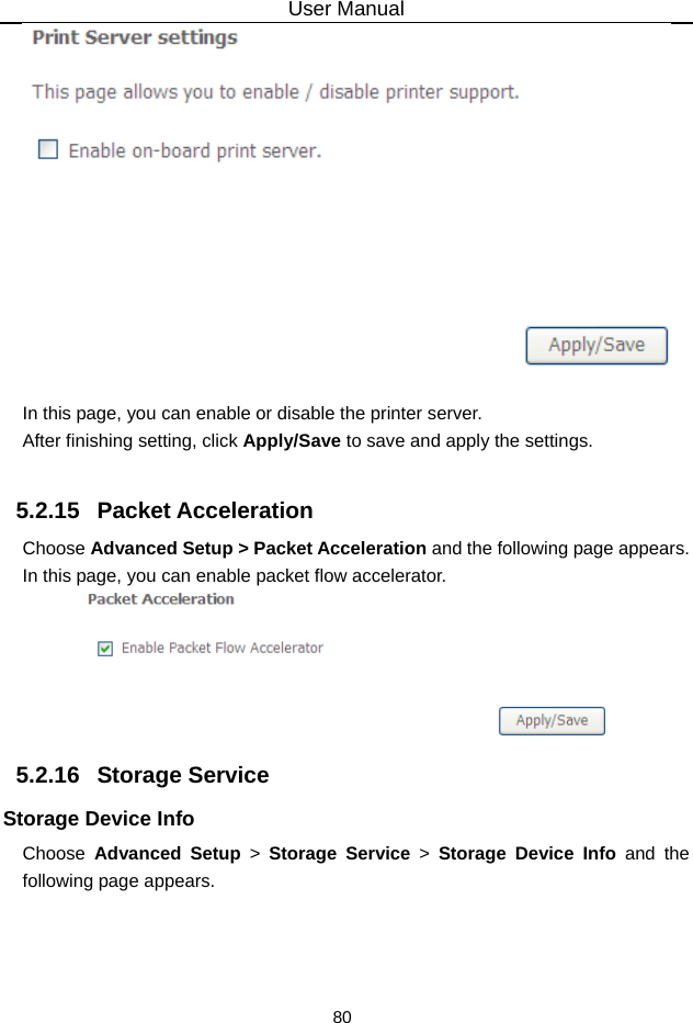
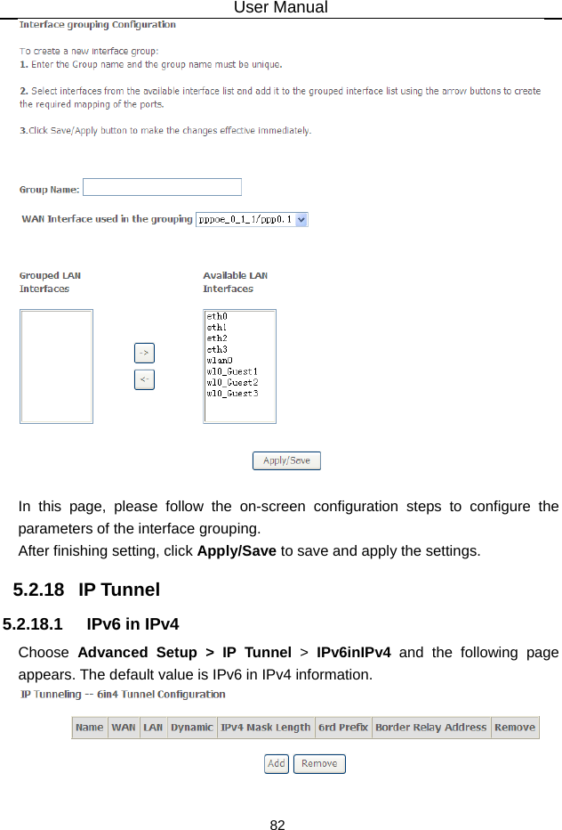
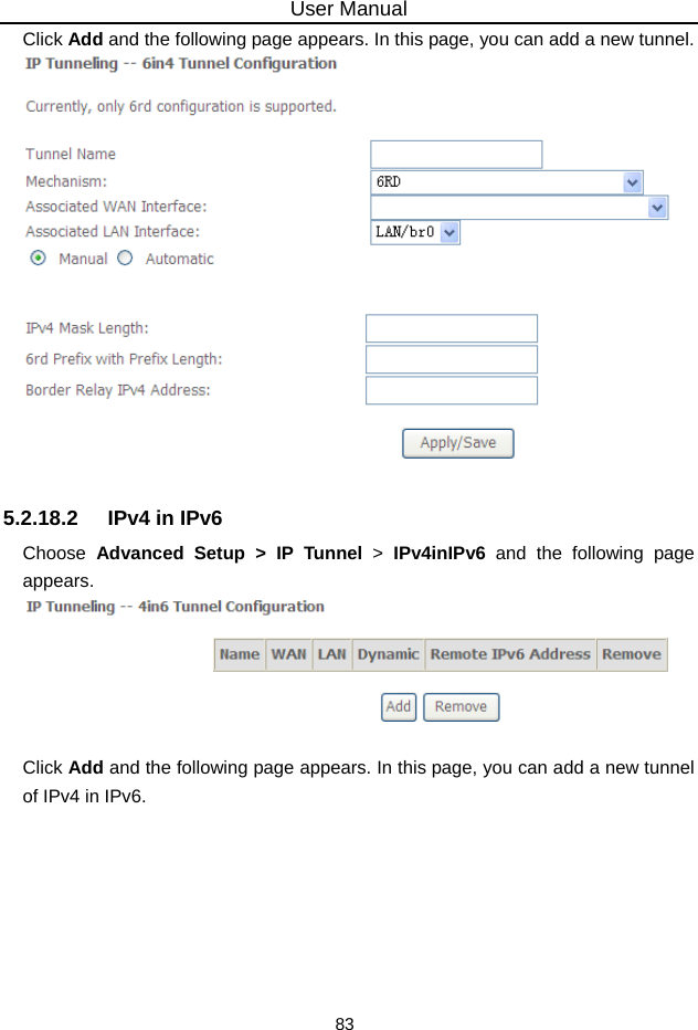
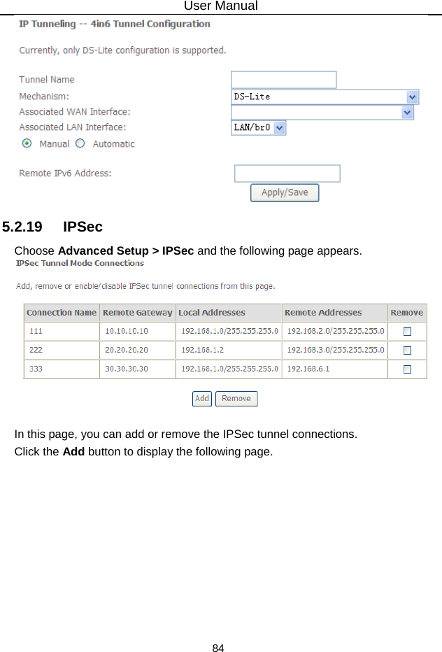
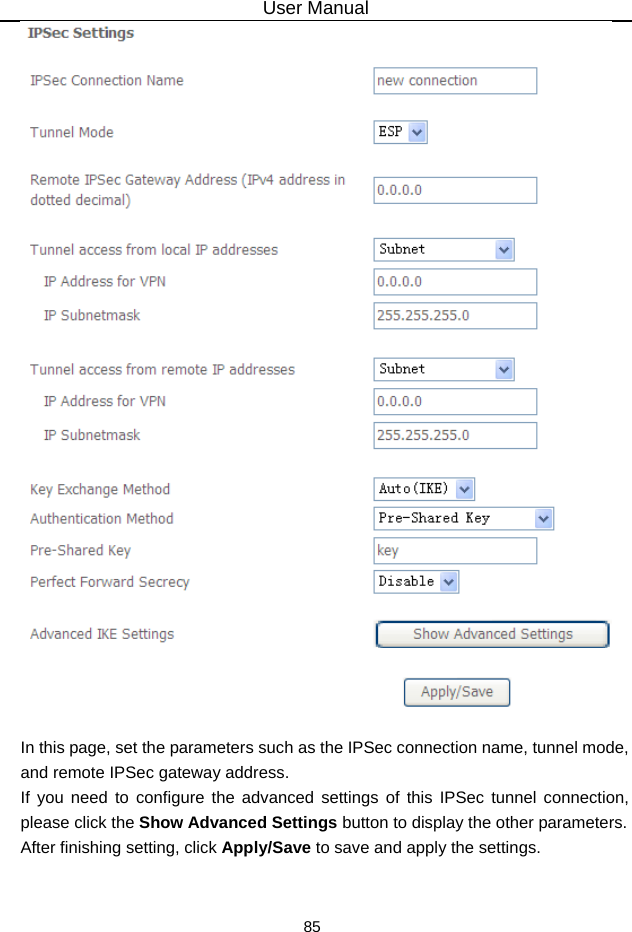
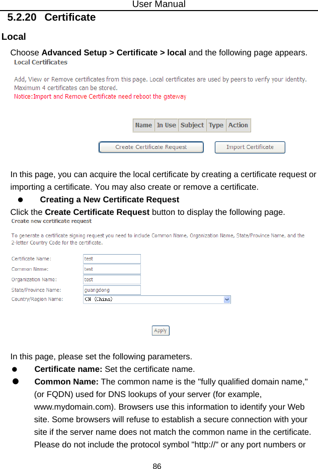
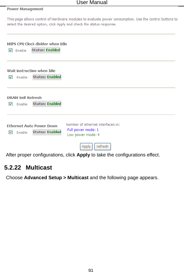
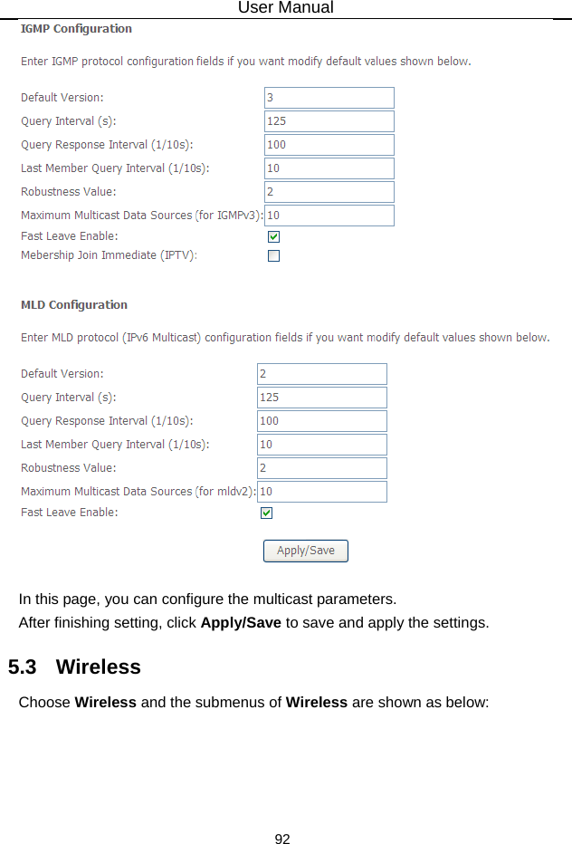
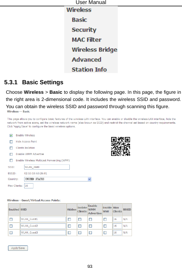
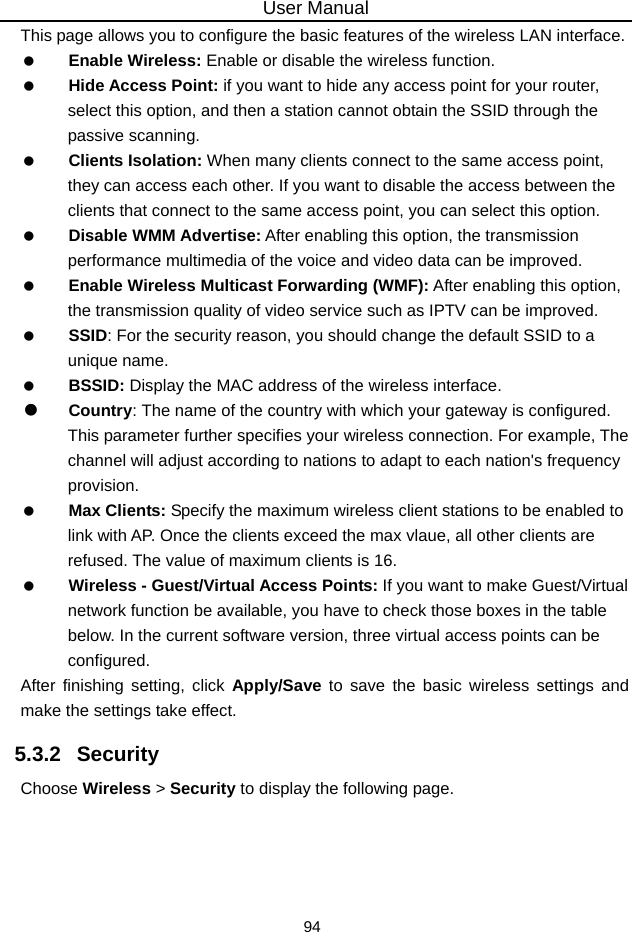
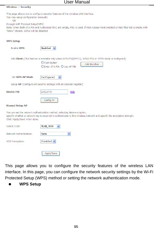
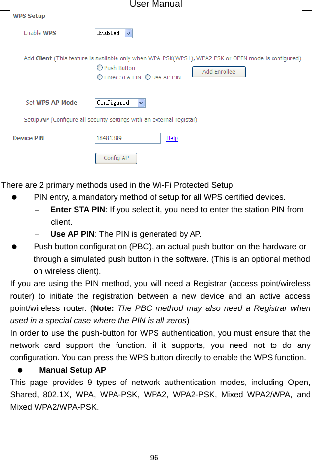
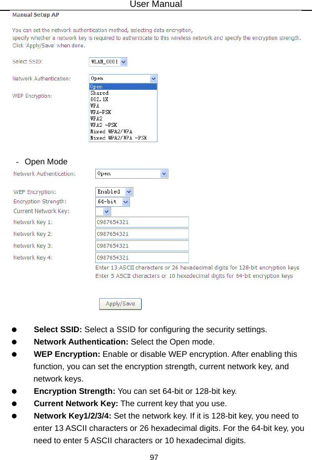
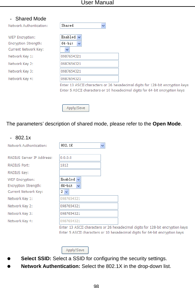
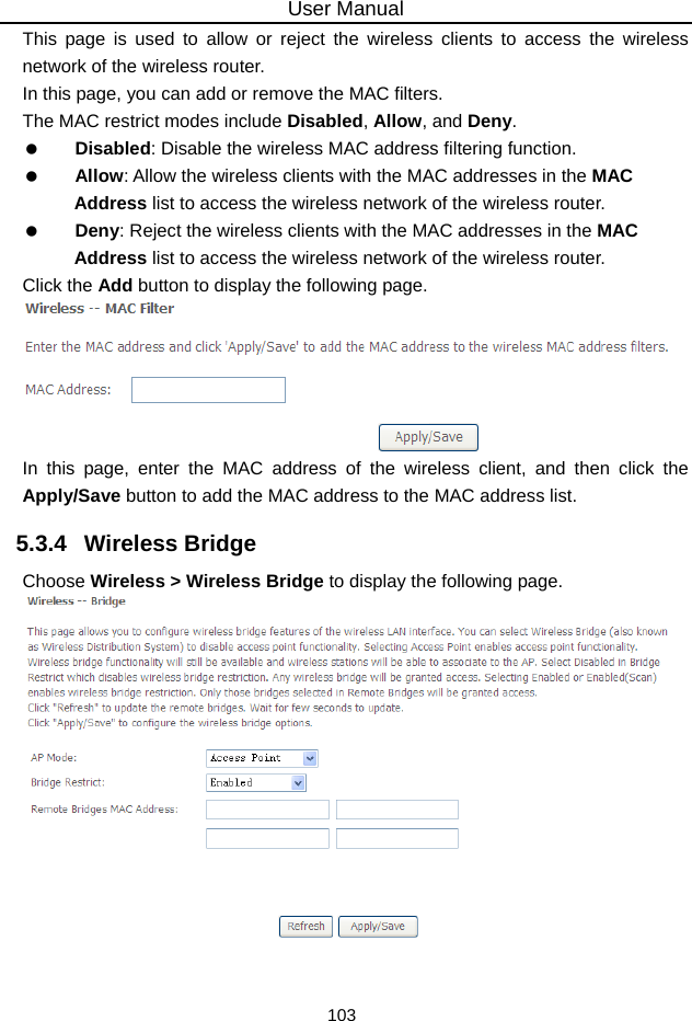
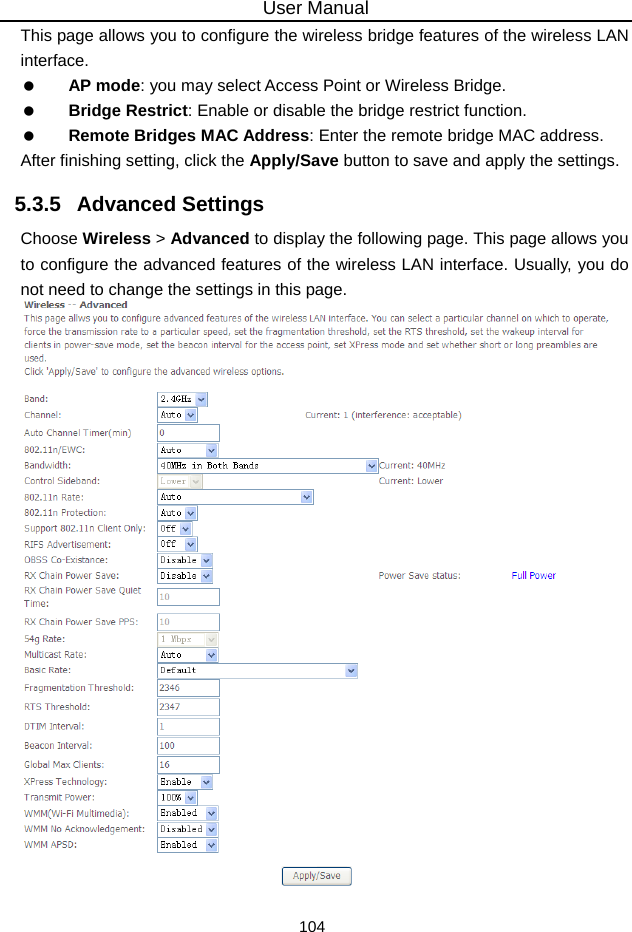
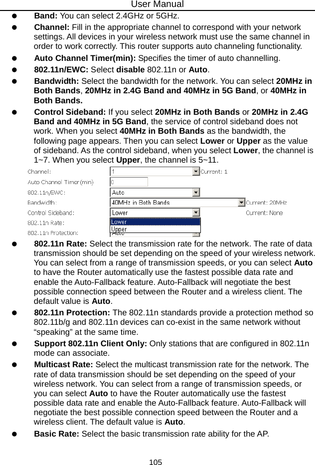
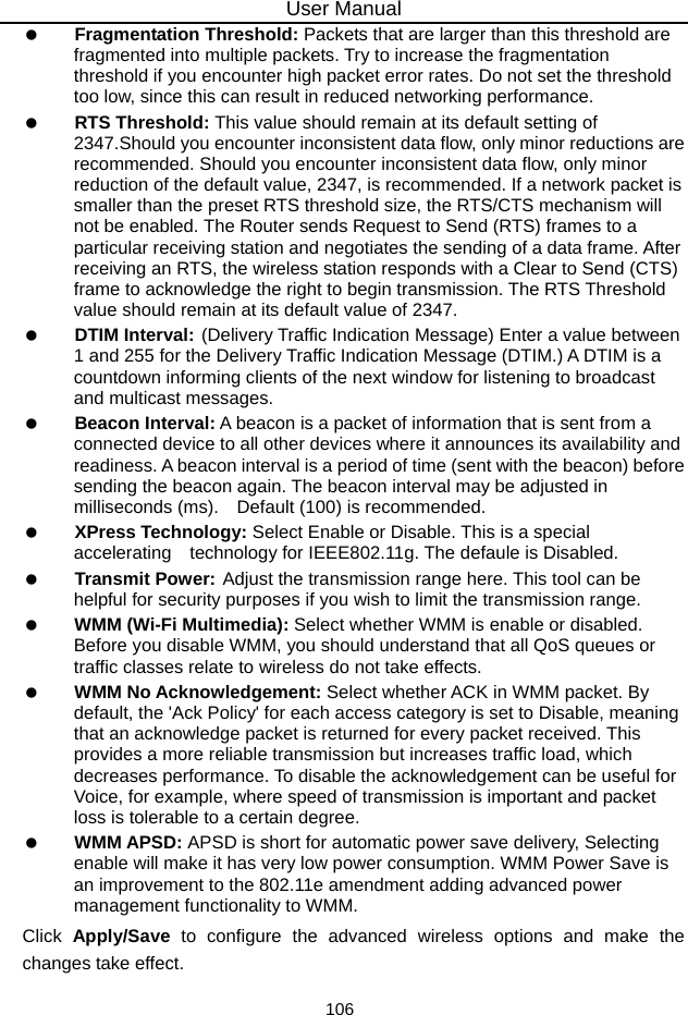
User Manual
Navigation menu
Upload a User Manual
Namespaces
Wiki Guide
HTML
PDF
Info
Views
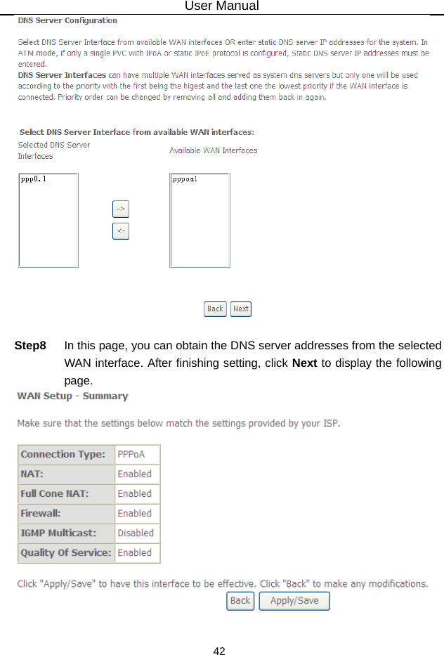
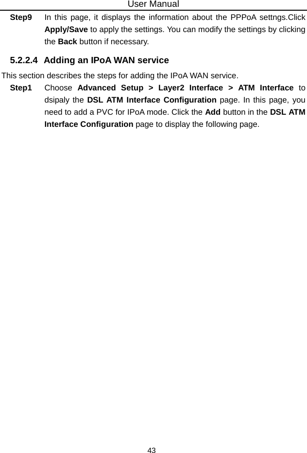
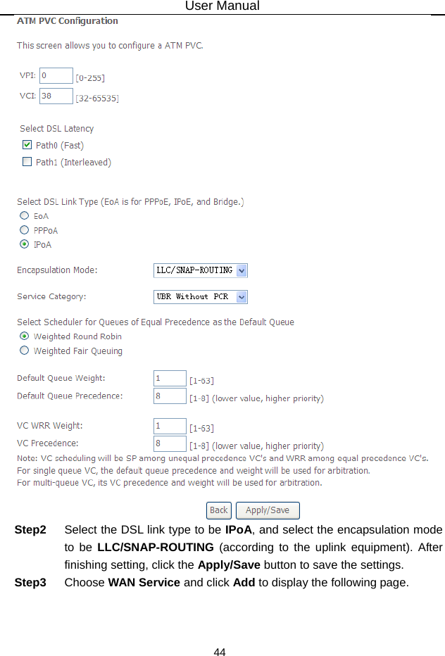
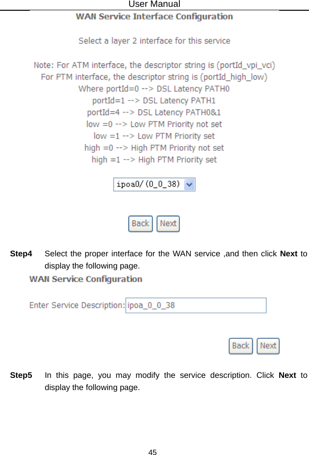
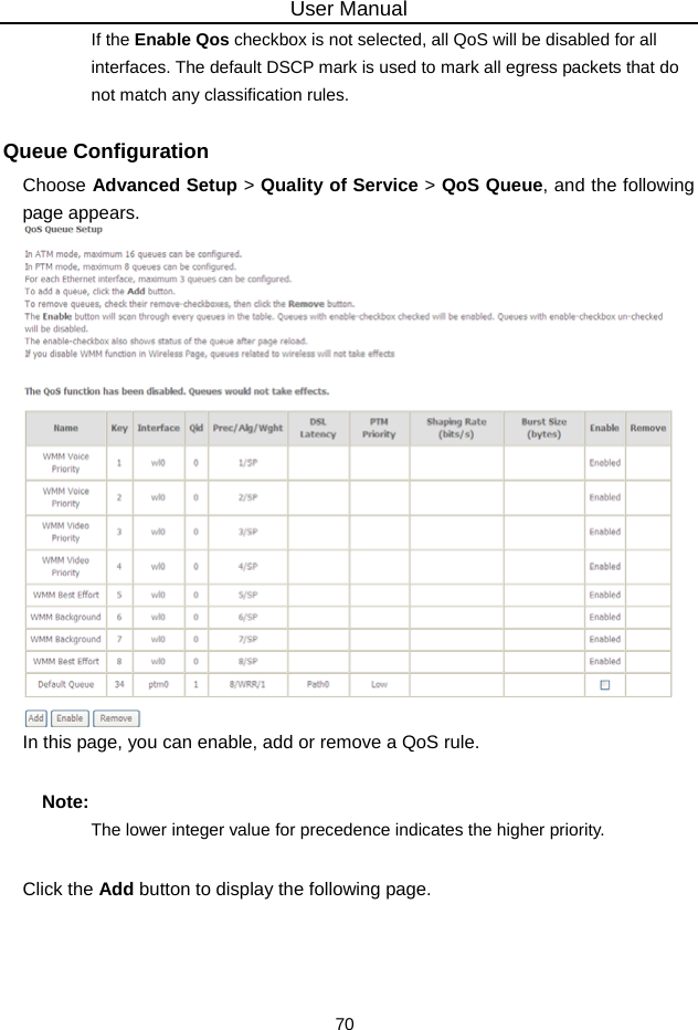
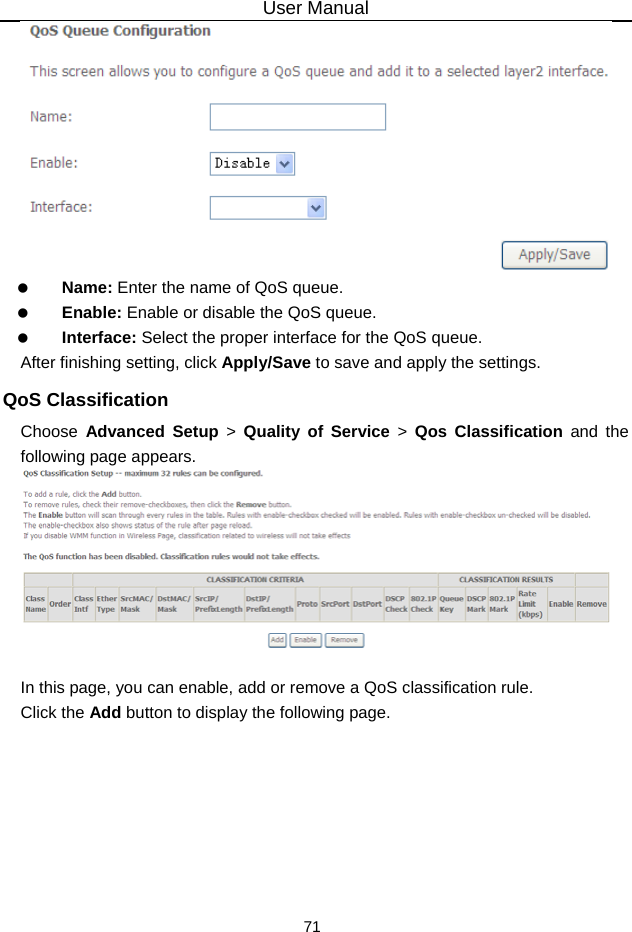
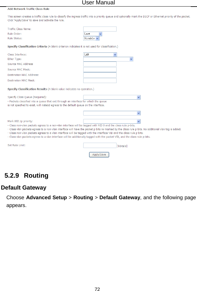
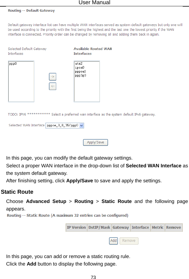
User Manual
Discussion / Help
Navigation