DLP Design 000RF1 USB Short Range Transceiver User Manual DLP RF1 Data Sheet
DLP Design, Inc. USB Short Range Transceiver DLP RF1 Data Sheet
UserManual.wiki
>
DLP Design
>
000RF1 User Manual
Users Manual Revised
Navigation menu
Upload a User Manual
Namespaces
Wiki Guide
HTML
PDF
Info
Views
User Manual
Discussion / Help
Navigation
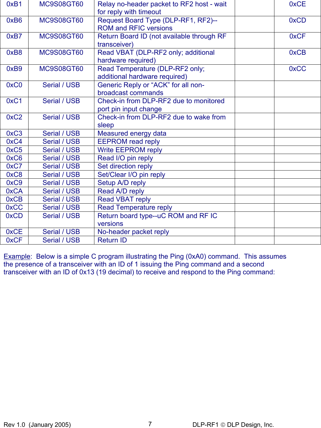
![Rev 1.0 (January 2005) DLP-RF1 DLP Design, Inc. 8 int m_DestID = 0x13; int m_SourceID = 0x01; unsigned char rx[126], tx[126]; int pos=1;//init packet index tx[pos++] = (unsigned char)((m_DestID&0xff00)>>8); //Destination ID MSB tx[pos++] = (unsigned char)(m_DestID&0x00ff); //Destination ID LSB tx[pos++] = (unsigned char)((m_SourceID&0xff00)>>8); //Source ID MSB tx[pos++] = (unsigned char)(m_SourceID&0x00ff); //Source ID LSB tx[pos++] = 0xA0;//Command byte: Ping tx[0] = pos-1;//assign number of bytes in packet to position zero PutBuffer(tx, pos);//send tx out serial port (actually USB) GetBuffer(rx, 6, TIMEOUTWAIT); //wait up to timeout for 6 bytes to return if(rx[5] != 0xC0)//if Buffer Position 5 is not the expected reply (0XC0) { //No reply to the Ping command //either retry the command or process the error } 4.0 USB Interface The VCP (Virtual COM Port) USB drivers can be downloaded from the bottom of the page at www.dlpdesign.com. [Windows XP (SP1 or later) and Linux (Kernel 2.4.0 or later) users do not need to download drivers as they are already part of the operating system.] Unzip the drivers into a folder on the PC’s hard drive. The USB driver installation process is initiated by connecting a DLP-RF1 to the host PC. When prompted, point the driver installer to the folder in which the VCP drivers reside. The DLP-RF1 uses a USB interface design similar to that used by the DLP-USB245M USB adapter module in that the connection between the USB IC and MC9S08GT60 consists of 8 data lines and 5 hand-shaking lines. Once the VCP drivers are installed, the DLP-RF1 appears to the host PC as a COM (RS232C) port. The application program running on the host PC simply has to open what appears to be an RS232C port then build and send a packet to gain access to/control of the DLP-RF1. The VCP drivers intercept the data packets on their way to the COM port and reroute them to the USB port. All packets returned from the DLP-RF1 simply appear in the receive buffer that was create when the COM port was opened. There is no need for the host application to set the baud rate of the opened COM port since data between the PC and DLP-RF1 flows at USB 1.1 “Full Speed” data rates, and the handshaking lines clock the data flowing between the USB IC and MC9S08GT60 over the 8-bit data bus. Since the host application is responsible for “retrying” any command packet that goes unanswered, the host application must wait an appropriate amount of time for all responses. The amount of time to wait for a reply is dependant upon several factors so it is best for the user to derive empirically (trial and error) the appropriate amount of time to wait.](https://usermanual.wiki/DLP-Design/000RF1/User-Guide-520494-Page-8.png)