DRTECH EVS3643 Flat Panel Digital X-ray Detector User Manual EVS 3643
DRTECH Corporation Flat Panel Digital X-ray Detector EVS 3643
UserManual.wiki
>
DRTECH
>
EVS3643 User Manual
User Manual
Navigation menu
Upload a User Manual
Namespaces
Wiki Guide
HTML
PDF
Info
Views
User Manual
Discussion / Help
Navigation


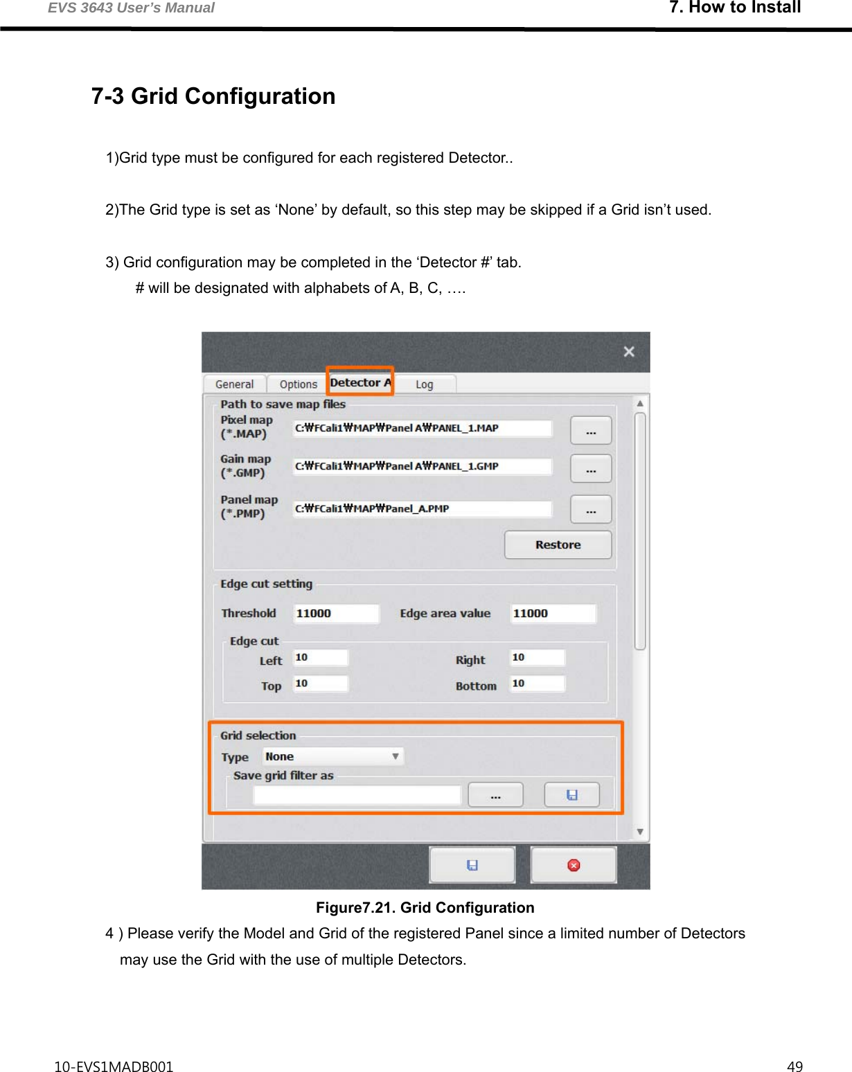
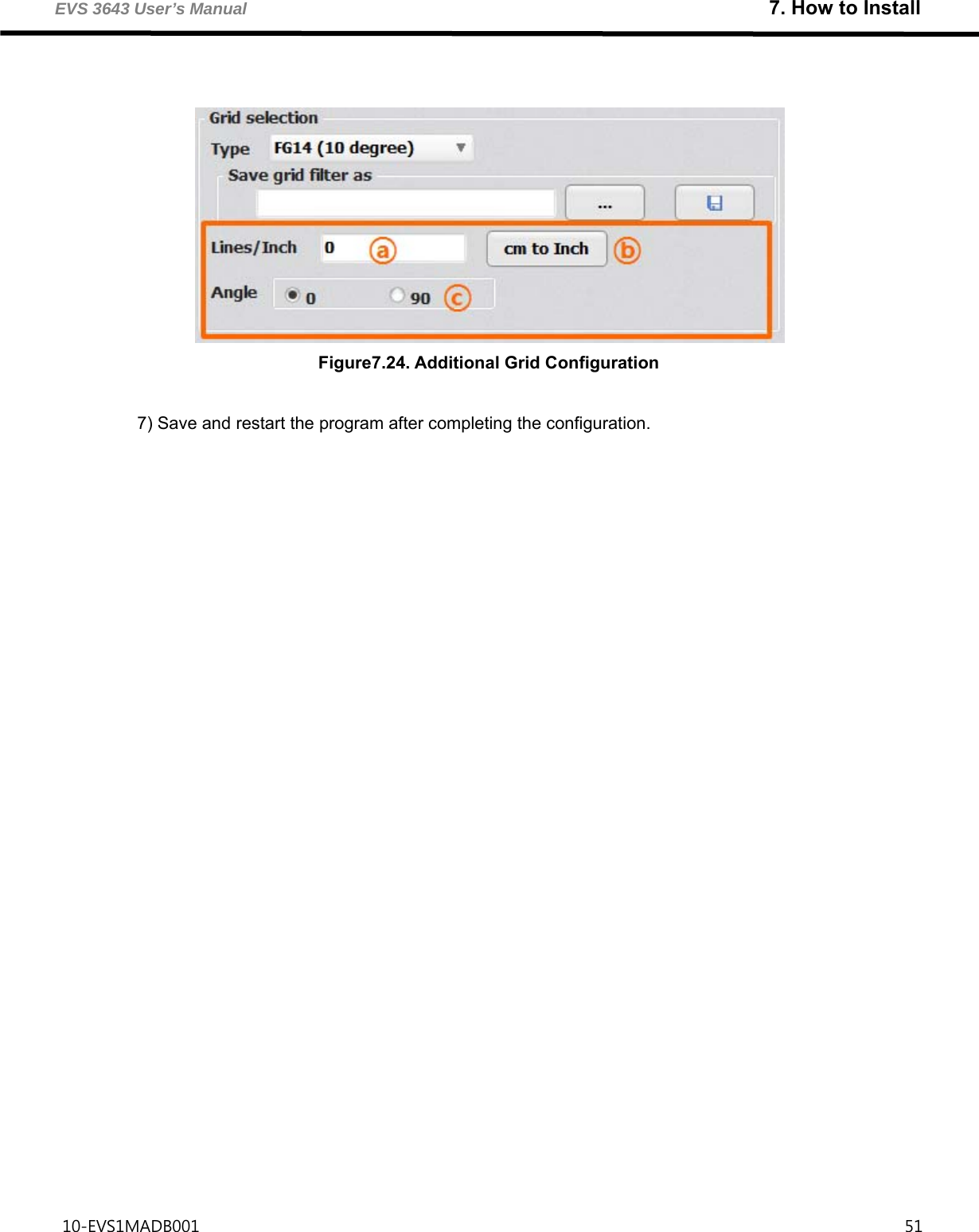
![EVS 3643 User’s Manual 7. How to Install 10-EVS1MADB001 50 5) Filter file must be registered after the configuration of Type. Figure7.22. Registering Grid Filter File ① Select the Filter file by selecting ‘…’ as in the figure. ② A file compatible with the configured Grid Type must be selected. ③ Filter file is located in the [ECali1 Installation Folder]\Filter Folder. ④ It is in the C:\ECali1\Filter folder by default. Figure 7.23. Filter File 6) Input the ⓐ Lines/Inch and ⓒ Angle in accordance with the Grid Type. The ⓑ cm to Inch button may be utilized to alter the units when entering the Lines/Inch, if the cm unit is known.](https://usermanual.wiki/DRTECH/EVS3643/User-Guide-2555737-Page-58.png)
![EVS 3643 User’s Manual 7. How to Install 10-EVS1MADB001 53 7-5 ECali1 UI Overview 7-5-1 Main Screen of the Program The main screen of ECali1 is as illustrated in [7.27]. Figure 7.27. Main Screen of ECali1 Category Title Reference ⓐ Menu Menu (p. 49) ⓑ Toolbar Toolbar (p. 53) ⓒ Pixel Map Toolbar Pixel Map Toolbar and Pixel Viewer (p. 66) ⓓ Thumbnail Thumbnail (p. 67) ⓔ Image Viewer Image Viewer (p. 68) ⓕ Pixel Viewer Pixel Map Toolbar and Pixel Viewer (p. 66) ⓖ Mini Map / Pixel Value 7-7 Mini Map and Pixel Value (p. 70) ⓗ Histogram Histogram (p. 71) ⓘ Status Bar Status Bar (p. 72)](https://usermanual.wiki/DRTECH/EVS3643/User-Guide-2555737-Page-61.png)
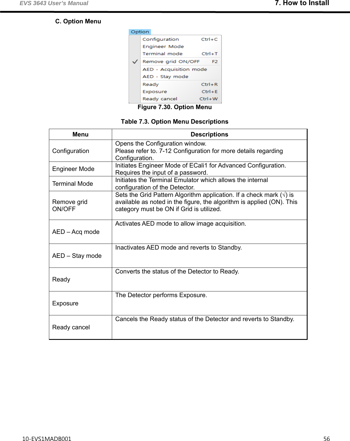
![EVS 3643 User’s Manual 7. How to Install 10-EVS1MADB001 54 1) Menu Corresponds to ⓐ in [Figure 7.27] and comprised of 5 menus, which are File, Tools, Option, Detector and Help. A. File Menu Figure 7.28. File Menu Table 7.1. File Menu Descriptions Menu Descriptions Load pixel map Loads the Pixel map file. Save pixel map Saves the Pixel map file. Load gain map Loads the Gain map file. Load panel map Loads the Panel map file. Load raw image Loads the RAW image file in .IMG1 format. Save raw image Saves the currently selected image as a RAW image file in .IMG format. Exit Exits ECali1. 1 .IMG file: Image Data file that has 16 bit gray-level pixel value](https://usermanual.wiki/DRTECH/EVS3643/User-Guide-2555737-Page-62.png)
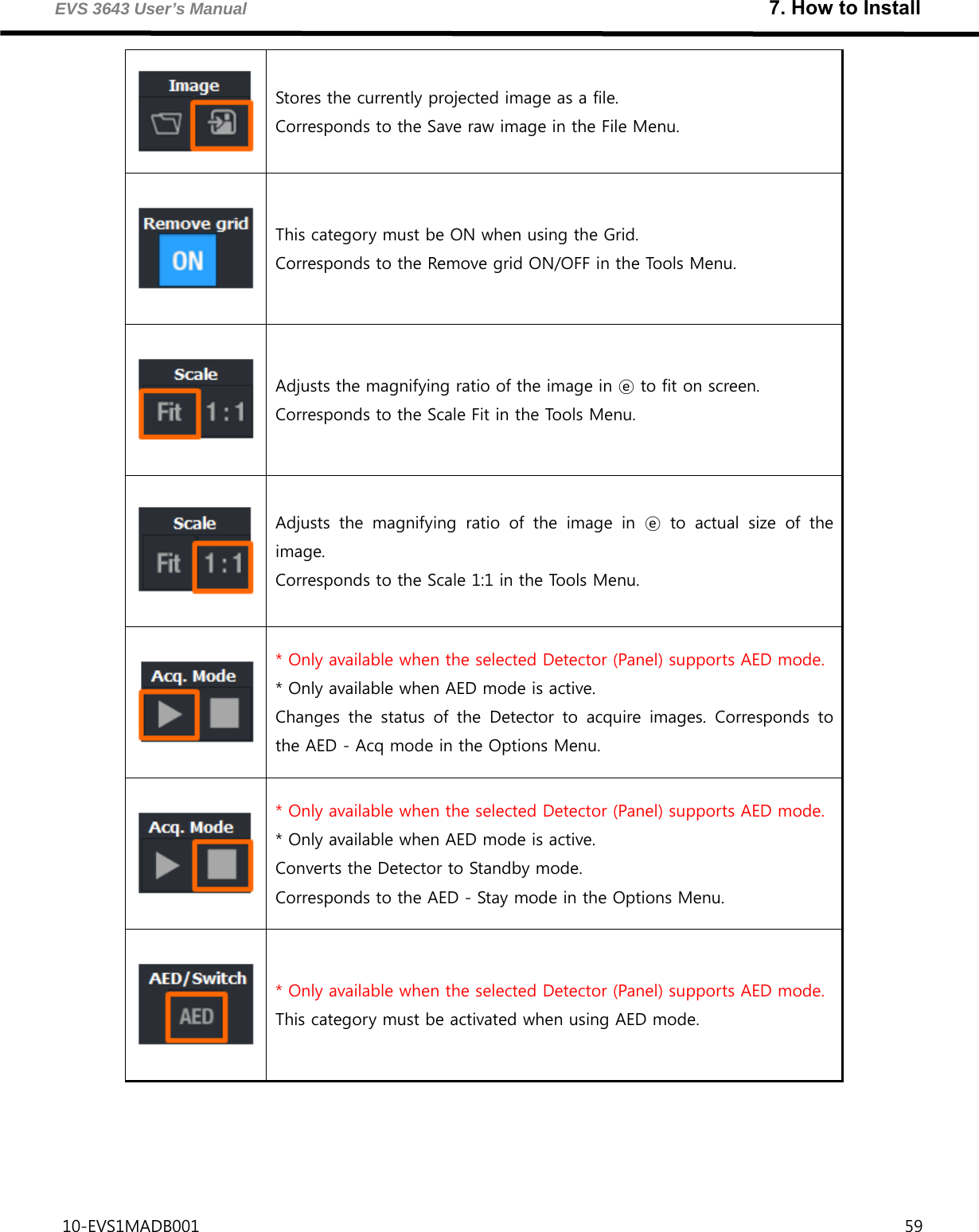
![EVS 3643 User’s Manual 7. How to Install 10-EVS1MADB001 58 7-5-2 Toolbar Corresponds to ⓑ in [7.27] and provides most used menus as Toolbar icons. Figure 7.33. Toolbar Table 7.6. Toolbar Icon Descriptions Icon Descriptions Performs Gain map calibration. Corresponds to the Gain map calibration in the Tools Menu. Performs Grid Calibration. Corresponds to the Grid map calibration in the Tools Menu. Loads and applies the Pixel map file. Corresponds to the Load pixel map in the File Menu. Stores the currently applied Pixel map as a file. Corresponds to the Save pixel map in the File Menu. Loads and applies the Gain map file. Corresponds to the Load Gain map in the File Menu. Loads and displays the projected image from the file. Corresponds to the Load raw image in the File Menu.](https://usermanual.wiki/DRTECH/EVS3643/User-Guide-2555737-Page-66.png)
![EVS 3643 User’s Manual 7. How to Install 10-EVS1MADB001 60 7-5-3 Pixel Map Toolbar and Pixel Viewer Corresponds to ⓒ and ⓕ in [Figure 7.27], and utilized when creating a Pixel Map. Figure7.34. Pixel Map Toolbar Figure 7.35. Pixel Viewer The selected area from the Image Viewer will be magnified and displayed in the Pixel Viewer. Please refer to 7-11 Pixel Correction for more details and methods of generating Pixel Maps.](https://usermanual.wiki/DRTECH/EVS3643/User-Guide-2555737-Page-68.png)
![EVS 3643 User’s Manual 7. How to Install 10-EVS1MADB001 61 7-5-4 Thumbnail Corresponds to ⓓ in [Figure 7.27]. Displays the Thumbnail of the projected image, and allows the user to select a specific image between multiple images. If there are a significant number of projected images, a scroll button on the top and bottom allows the user to select a specific image. Select the Thumbnail to be deleted and select ‘Delete’ if a re-projection is required during the calibration. The selected image will be deleted and a re-projection may be performed. The following information will be displayed if an image is loaded from a file. The file name will be displayed on the top left. STD: Standard Deviation Value of the Pixel value of the image. Mean: Mean value of the pixel value of the image. Figure 7.37. Thumbnail Information Figure 1.36. Thumbnail](https://usermanual.wiki/DRTECH/EVS3643/User-Guide-2555737-Page-69.png)
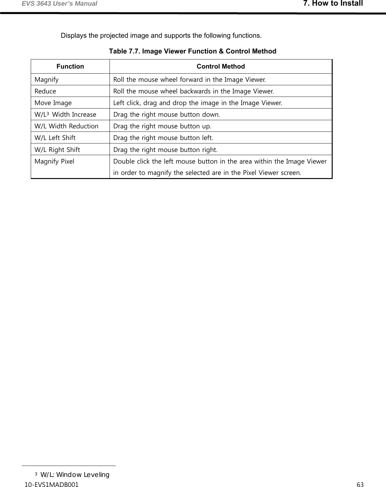
![EVS 3643 User’s Manual 7. How to Install 10-EVS1MADB001 62 7-6 Image Viewer Corresponds to ⓔ in [Figure 7.27]. Figure 7.38. Image Viewer](https://usermanual.wiki/DRTECH/EVS3643/User-Guide-2555737-Page-70.png)
![EVS 3643 User’s Manual 7. How to Install 10-EVS1MADB001 64 7-7 Mini Map and Pixel Value Corresponds to ⓖ in [Figure 7.27] 7-7-1 Mini Map Figure 7.39. Mini Map Allows the users to verify the area currently being viewed in the Image Viewer. The area within the green dotted boarder is the area currently displayed in the Image Viewer. 7-7-2 Pixel Value Figure 7.40. Pixel Value Displays the pixel value of the location the mouse cursor is hovering in the Image Viewer or the Pixel Viewer.](https://usermanual.wiki/DRTECH/EVS3643/User-Guide-2555737-Page-72.png)
![EVS 3643 User’s Manual 7. How to Install 10-EVS1MADB001 65 7-8 Histogram Corresponds to ⓗ in [Figure 7.24] Displays the Histogram of the selected image Figure7.41. Histogram Supports Dynamic or Static mode subsequent to the Windows Leveling conditions 7-8-1 Dynamic The minimum and maximum values will be fixed while the Histogram values may be adjusted if Window Leveling is attempted in the Image Viewer while in Dynamic mode. 7-8-2 Static The Histogram values will be fixed while the minimum and maximum values may be adjusted if Window Leveling is attempted in the Image Viewer while in Static mode.](https://usermanual.wiki/DRTECH/EVS3643/User-Guide-2555737-Page-73.png)
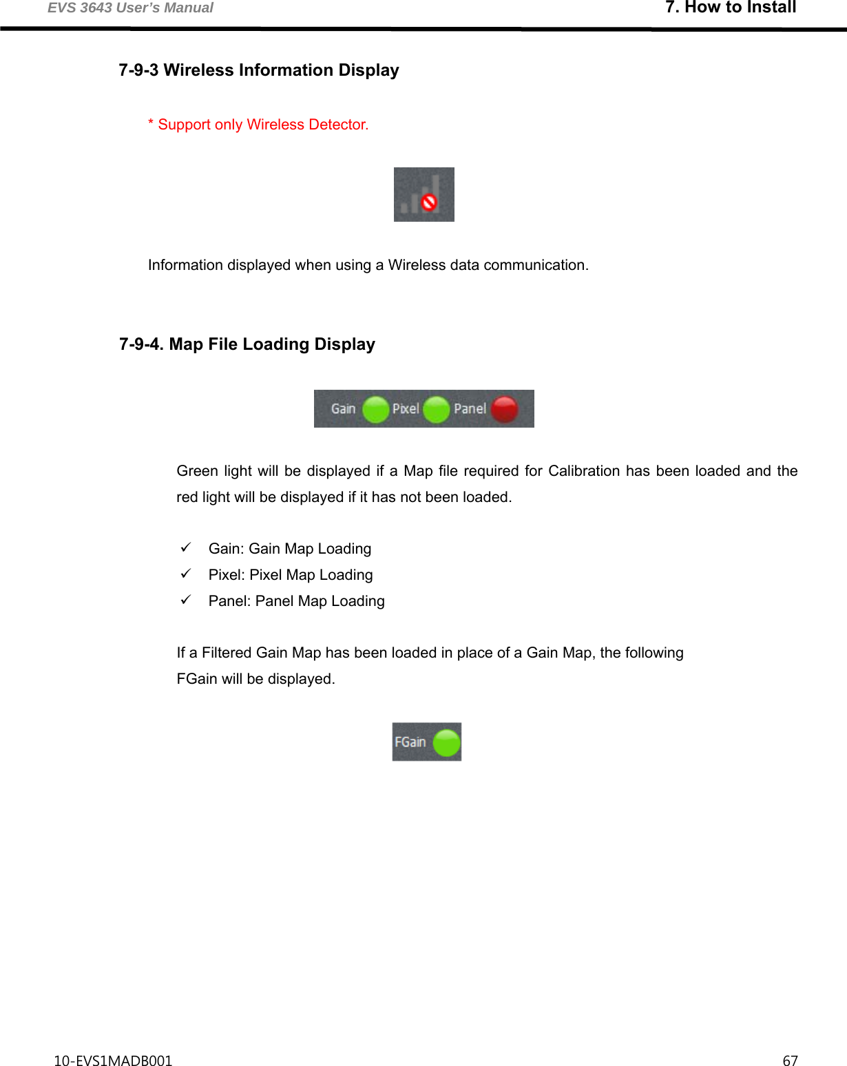
![EVS 3643 User’s Manual 7. How to Install 10-EVS1MADB001 66 7-9 Status Bar Corresponds to ⓘ in [Figure 7.27] 7-9-1 Image Information Display Displays various information of the image ① Current axis and Pixel value of the mouse cursor Displayed as (X : [X Axis] Y : [Y Axis]) = [Pixel Value] ② Mean: Mean Pixel Value of the image ③ STD: Standard Deviation of the Pixel value of the image ④ Min: Minimum value of the image Histogram ⑤ Max: Maximum value of the image Histogram ⑥ Peak: The Peak value and its Position of the image Histogram Displayed as [Peak Value] at [Position] 7-9-2 Detector Status Display * Supports only Ethernet Type and F600. A green light will be displayed if the Detector is able to take a projection and a red light will be displayed if the Detector is unable to take a projection. Figure7.42. Status Bar ① ② ③ ④ ⑤](https://usermanual.wiki/DRTECH/EVS3643/User-Guide-2555737-Page-74.png)
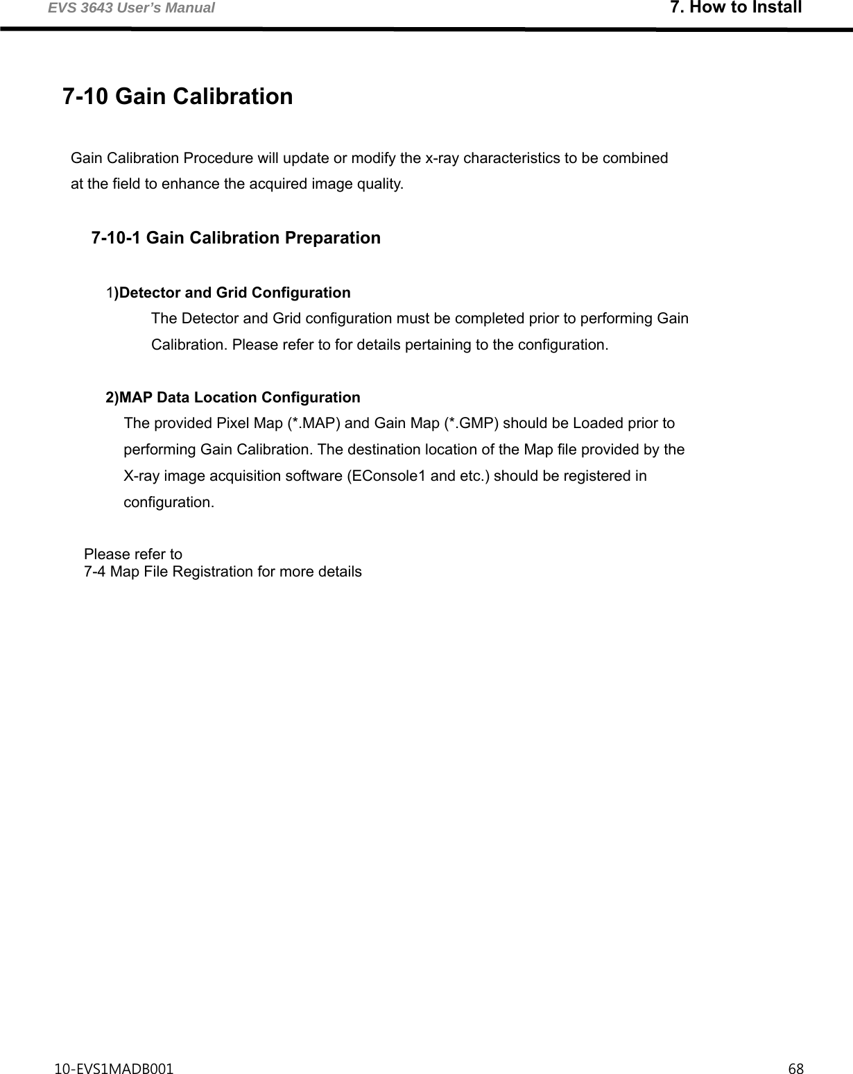
![EVS 3643 User’s Manual 7. How to Install 10-EVS1MADB001 69 7-10-2 Gain Calibration Actual X-ray must be shot to project an image in order to perform Gain Calibration. The Gain Calibration projection conditions are as follows. [Ta ble 7 - 8 ] Table 7.8. Gain Calibration Condition Conditions Descriptions Grid application Projection must be taken without the application of Grid. (Cautions) The Grid Type must be set ‘None’ in Configuration - Detector - Grid selection - Type before Gain Calibration, and must be restored after Gain Calibration. Subject Projection must be done without a subject X-ray exposure X-ray exposure is required X-ray radiation dose Adjust the mean pixel value of the projected image to be between 3,000 ~ 4,000 X-ray Condition example) 70kVp, 200mA, 2mAs SID Stand: 150 cm, Table: 100 cm Number of projections Default Value: 7 counts Configuration possible in Configuration - General - Calibration - Count. Projection interval Default Value: 60 Seconds Configuration possible in Configuration - General - Calibration - Interval. Other things Collimator should be open maximally X-ray should be set to be exposed in the whole Detector Detector should be aligned in the center](https://usermanual.wiki/DRTECH/EVS3643/User-Guide-2555737-Page-77.png)
![EVS 3643 User’s Manual 7. How to Install 10-EVS1MADB001 74 The Gain Calibration results are automatically saved as Gain Map (*.GMP) when all required images are projected and the existing files are backed-up. Figure7.55. Notification for Gain Calibration Completion The existing GMP files are backed up in the [ECali1 Installation Folder]\MAP folder. The file name is as follows. [7-56] Figure7.56. Example of a Back-up File](https://usermanual.wiki/DRTECH/EVS3643/User-Guide-2555737-Page-82.png)
![EVS 3643 User’s Manual 7. How to Install 10-EVS1MADB001 78 Figure 7.59. Display the Horizontal Line Defect Area in Pixel Viewer A defect of a point or line may exist for each Detector. [7-59] illustrates a Horizontal Line Defect. There are 3 types for Pixel Correction. Figure 7.60. Pixel Defects](https://usermanual.wiki/DRTECH/EVS3643/User-Guide-2555737-Page-86.png)
![EVS 3643 User’s Manual 7. How to Install 10-EVS1MADB001 79 The following are utilized to perform Pixel Correction. [Figure7-61] Figure 7.61. Pixel Correction Icon Pixel Correction is performed in the following process. ① Display the Pixel Defect in the Pixel Viewer ② Select the appropriate shortcut icon ③ Ctrl+Left Click the area of Defect in the Pixel Viewer Figure 7.62. Pixel Correction (Horizontal Line Defect)](https://usermanual.wiki/DRTECH/EVS3643/User-Guide-2555737-Page-87.png)

![EVS3643 User’s Manual 10. Specifications 10-EVS1MADB001 91 10-1. Main specifications EVS 3643 X-ray detector [Dimensional diagram] (unit mm)](https://usermanual.wiki/DRTECH/EVS3643/User-Guide-2555737-Page-99.png)
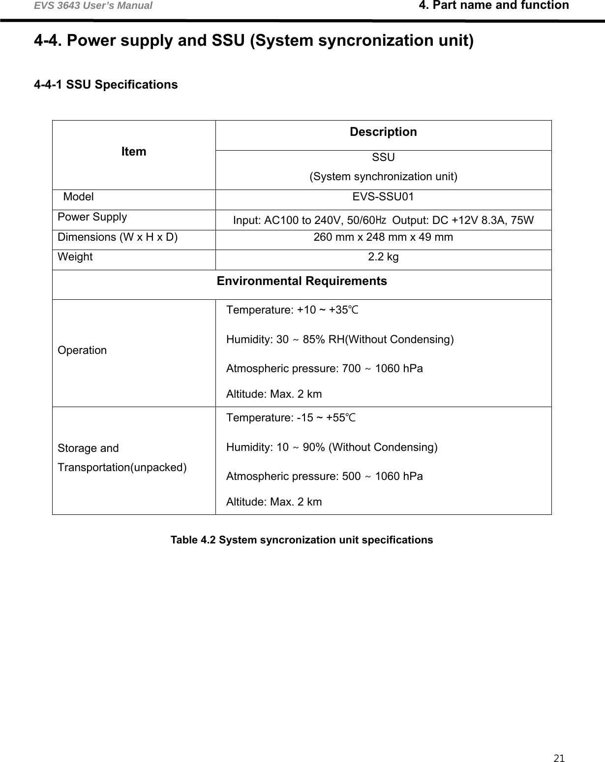
![EVS 3643 User’s Manual 10 Specifications 10-EVS1MADB001 92 SSU (System Syncronization Unit) [Dimensional diagram] (unit mm) Rated power supply Input: 100-240 VAC, 50/60Hz Output: DC +12 V 8.3A, 75W](https://usermanual.wiki/DRTECH/EVS3643/User-Guide-2555737-Page-100.png)


![EVS 3643 User’s Manual 11. Regulatory information 10-EVS1MADB001 97 For European Union (and EEA) English Hereby, DRTECH Inc., declares that this EVS-3643 Wireless is in compliance with the essential requirements and other relevant provisions of Directive 1999/5/EC. Česky DRTECH Inc. tímto prohlašuje, že tento EVS 3643 Wireless je ve shodě se základními požadavky a dalšími příslušnými ustanoveními směrnice 1999/5/ES. Dansk Undertegnede DRTECH Inc. erklærer herved, at følgende udstyr EVS 3643 Wireless overholder de væsentlige krav og øvrige relevante krav i direktiv 1999/5/EF. Deutsch Hiermit erklärt DRTECH Inc., dass sich das Gerät EVS 3643 Wireless in Übereinstimmung mit den grundlegenden Anforderungen und den übrigen einschlägigen Bestimmungen der Richtlinie 1999/5/EG befindet. Eesti Käesolevaga kinnitab DRTECH Inc. seadme EVS 3643 Wireless vastavust direktiivi 1999/5/EÜ põhinõuetele ja nimetatud direktiivist tulenevatele teistele asjakohastele sätetele. Español Por medio de la presente DRTECH Inc. declara que el EVS 3643 Wireless cumple con los requisitos esenciales y cualesquiera otras disposiciones aplicables o exigibles de la Directiva 1999/5/CE. Ελληνική ΜΕ ΤΗΝ ΠΑΡΥΣΑ DRTECH Inc. ∆ΗΛΩΝΕΙ ΤΙ EVS 3643 Wireless ΣΥΜΜΡΦΩΝΕΤΑΙ ΠΡΣ ΤΙΣ ΥΣΙΩ∆ΕΙΣ ΑΠΑΙΤΗΣΕΙΣ ΚΑΙ ΤΙΣ ΛΙΠΕΣ ΣΕΤΙΚΕΣ ∆ΙΑΤΑΕΙΣ ΤΗΣ ∆ΗΓΙΑΣ 1999/5/ΕΚ. Français Par la présente DRTECH Inc. déclare que l’appareil EVS 3643 Wireless est conforme aux exigences essentielles et aux autres dispositions pertinentes de la directive 1999/5/CE. Italiano Con la presente DRTECH Inc. dichiara che questo EVS 3643 Wireless è conforme ai requisiti essenziali ed alle altre disposizioni pertinenti stabilite dalla direttiva 1999/5/CE. Latviski Ar šo DRTECH Inc. deklare, ka EVS 3643 Wireless atbilst Direktivas 1999/5/EK butiskajam prasibam un citiem ar to saistitajiem noteikumiem. Lietuviu Šiuo DRTECH Inc. deklaruoja, kad šis EVS 3643 Wireless atitinka esminius reikalavimus ir kitas 1999/5/EB Direktyvos nuostatas. Nederlands Hierbij verklaart DRTECH Inc. dat het toestel EVS 3643 Wireless in overeenstemming is met de essentiële eisen en de andere relevante bepalingen van richtlijn 1999/5/EG. Malti Hawnhekk, DRTECH Inc., jiddikjara li dan EVS 3643 Wireless jikkonforma malhtigijiet essenzjali u ma provvedimenti ohrajn relevanti li hemm fid-Dirrettiva 1999/5/EC. Magyar Alulírott, DRTECH Inc. nyilatkozom, hogy a EVS 3643 Wireless megfelel a vonatkozó alapvetõ követelményeknek és az 1999/5/EC irányelv egyéb elõírásainak. Polski Niniejszym DRTECH Inc. oswiadcza, ze EVS 3643 Wireless jest zgodny z zasadniczymi wymogami oraz pozostalymi stosownymi postanowieniami Dyrektywy 1999/5/EC. Português DRTECH Inc. declara que este EVS 3643 Wireless está conforme com os requisitos essenciais e outras disposições da Directiva 1999/5/CE. Slovensko DRTECH Inc. izjavlja, da je ta EVS 3643 Wireless v skladu z bistvenimi zahtevami in ostalimi relevantnimi dolocili direktive 1999/5/ES. Slovensky DRTECH Inc. týmto vyhlasuje, že [typ zariadenia] splna základné požiadavky a všetky príslušné ustanovenia Smernice 1999/5/ES. Suomi DRTECH Inc. vakuuttaa täten että EVS 3643 Wireless tyyppinen laite on direktiivin 1999/5/EY oleellisten vaatimusten ja sitä koskevien direktiivin muiden ehtojen mukainen. Svenska Härmed intygar DRTECH Inc. att denna EVS 3643 Wireless står I överensstämmelse med de väsentliga egenskapskrav och övriga relevant bestämmelser som framgår av direktiv 1999/5/EG. Íslenska Hér með lýsir DRTECH Inc. yfir því að EVS 3643 Wireless er í samræmi við grunnkröfur og aðrar kröfur, sem gerðar eru í tilskipun 1999/5/EC. Norsk DRTECH Inc. erklærer herved at utstyret EVS-3643 Wireless er i samsvar med de grunnleggende krav og øvrige relevante krav i direktiv 1999/5/EF.](https://usermanual.wiki/DRTECH/EVS3643/User-Guide-2555737-Page-105.png)