Damm Cellular Systems A S 104012 410 MHZ TRANSCEIVER MODULE User Manual TetraFlex 7 5 Manual
Damm Cellular Systems A/S 410 MHZ TRANSCEIVER MODULE TetraFlex 7 5 Manual
Contents
- 1. User Manual - 1
- 2. User manual - 2
- 3. User Manual - 3
- 4. User Manual - 4
- 5. Warning statements for user's manual
- 6. Notes to installer for user manual
- 7. Revised pages 4 and 5 of the user's manual 11 01 2012
- 8. User addendum 4 carrier 11 01 12
- 9. User addendum 8 carrier 11 01 2012
- 10. Note to installers to be placed in user manual
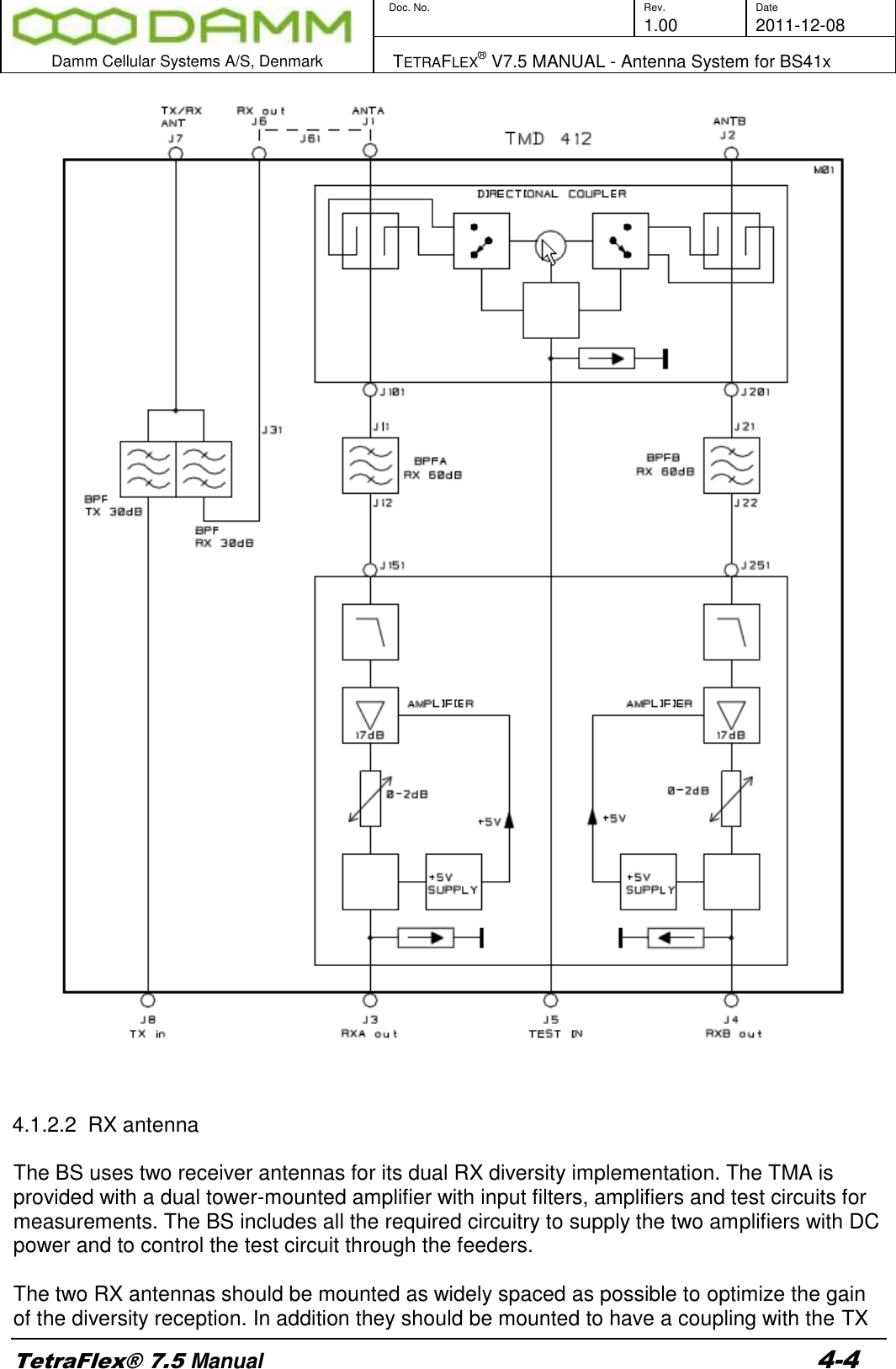
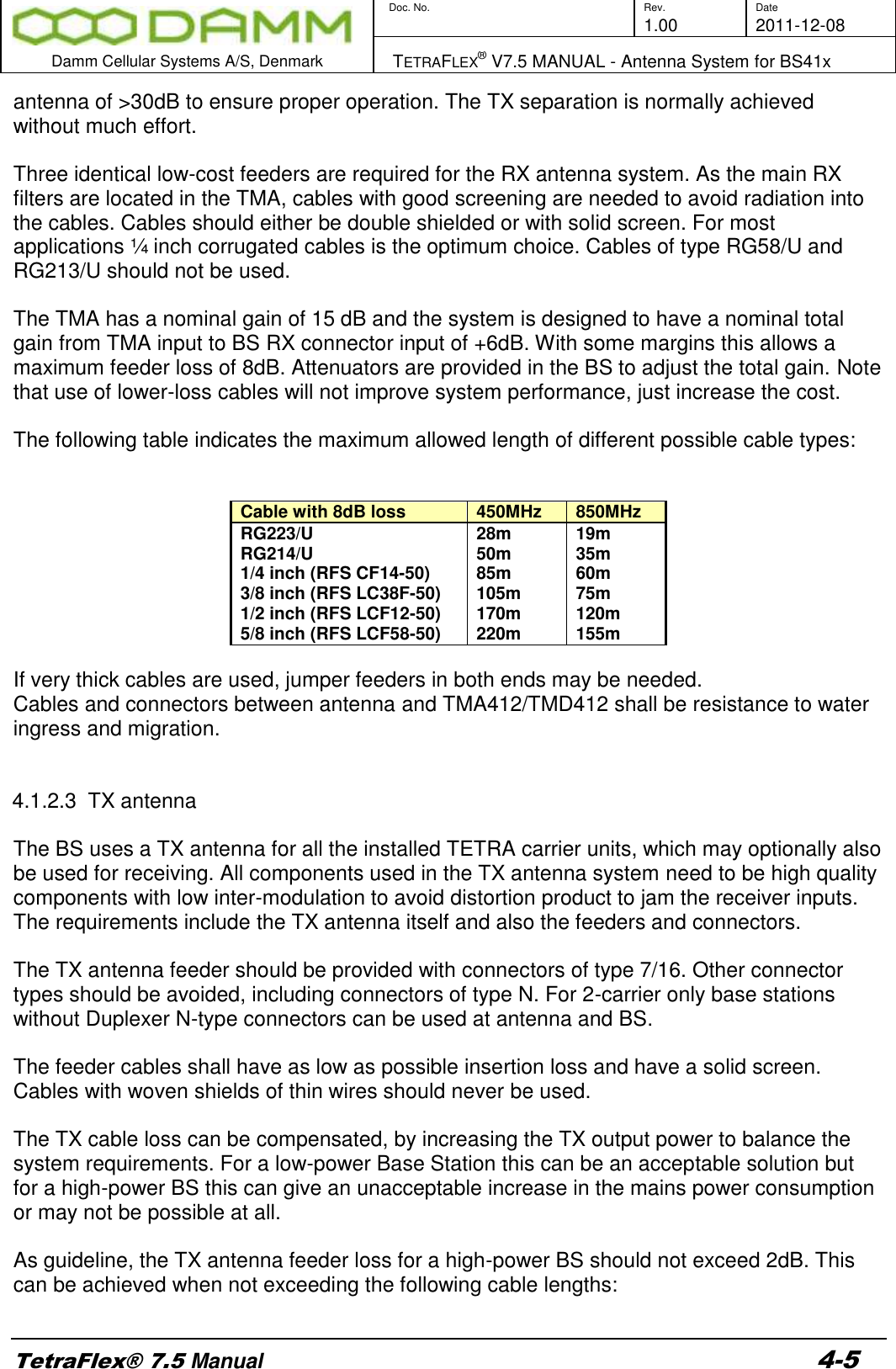
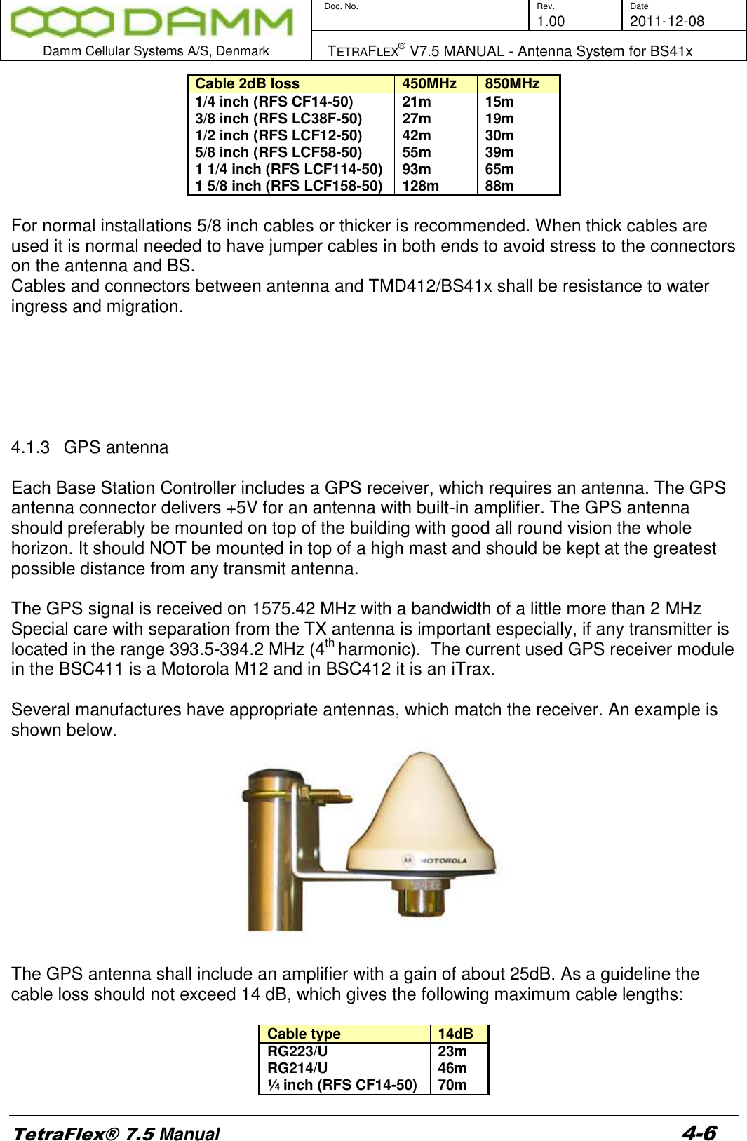
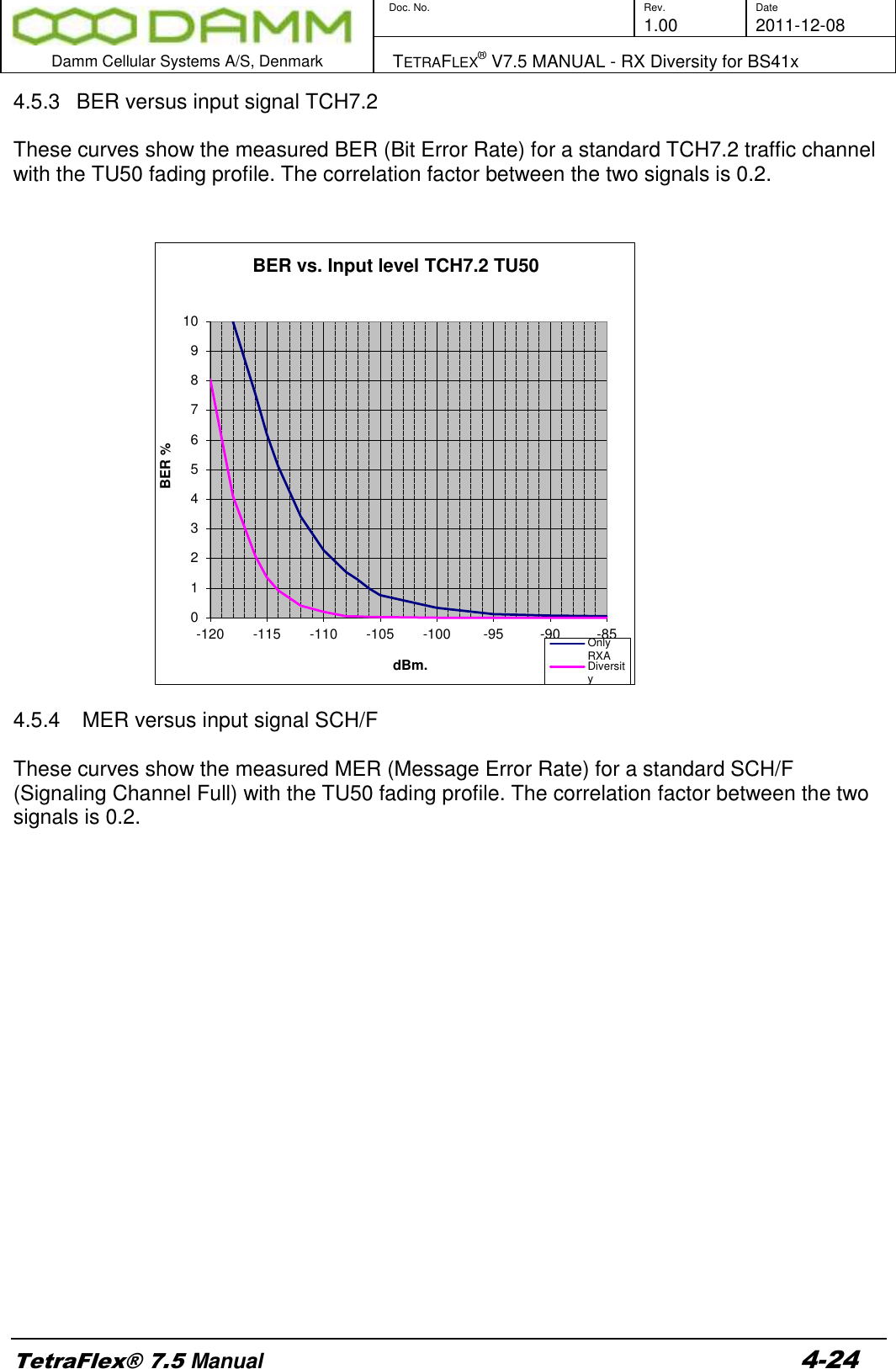
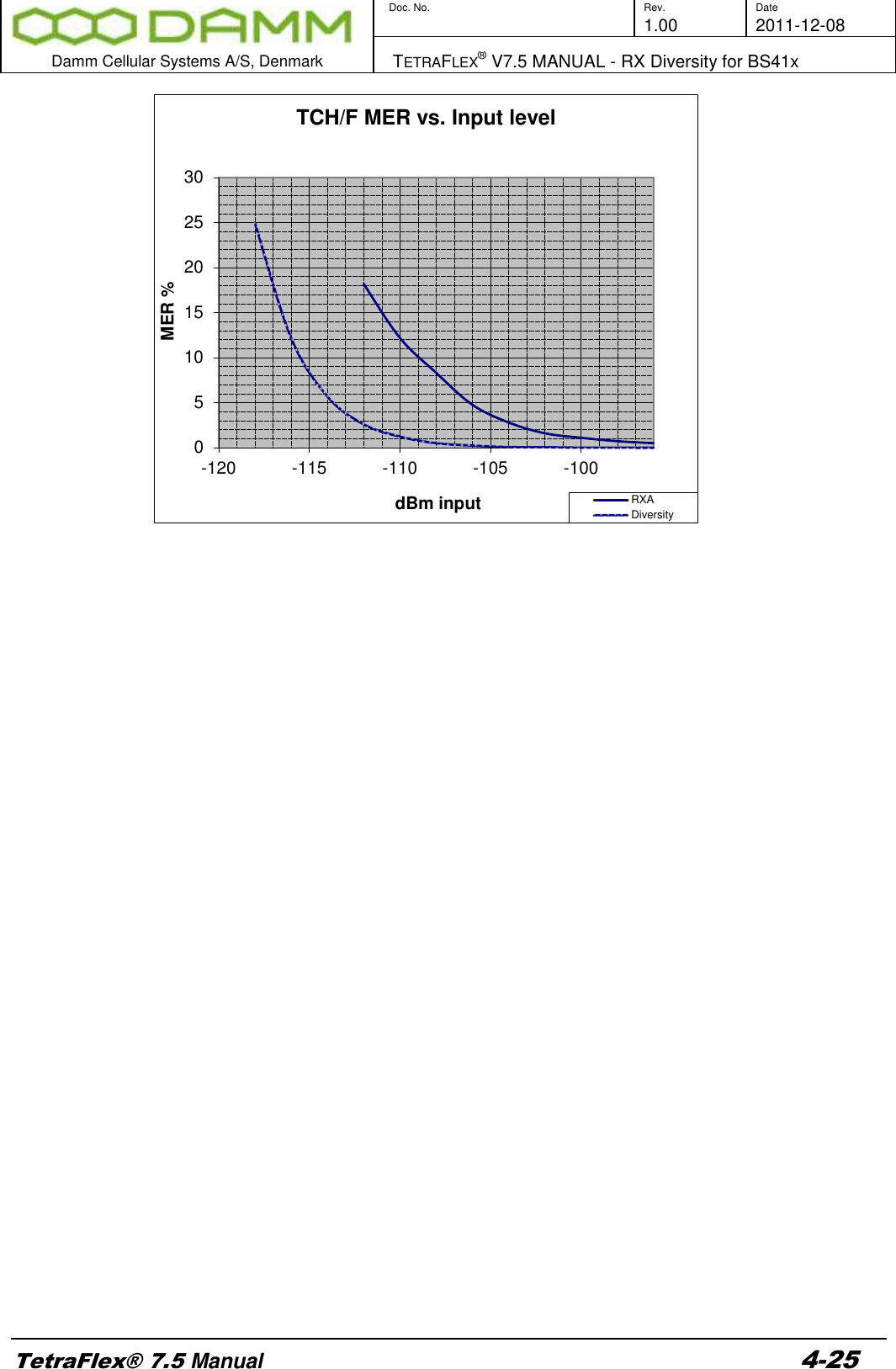
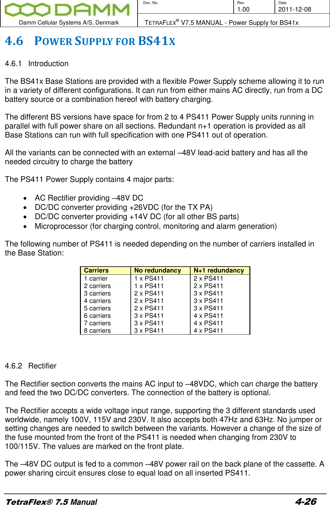
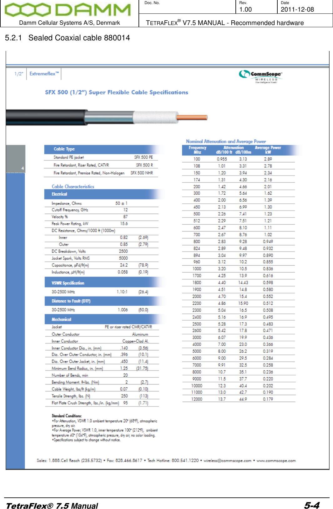
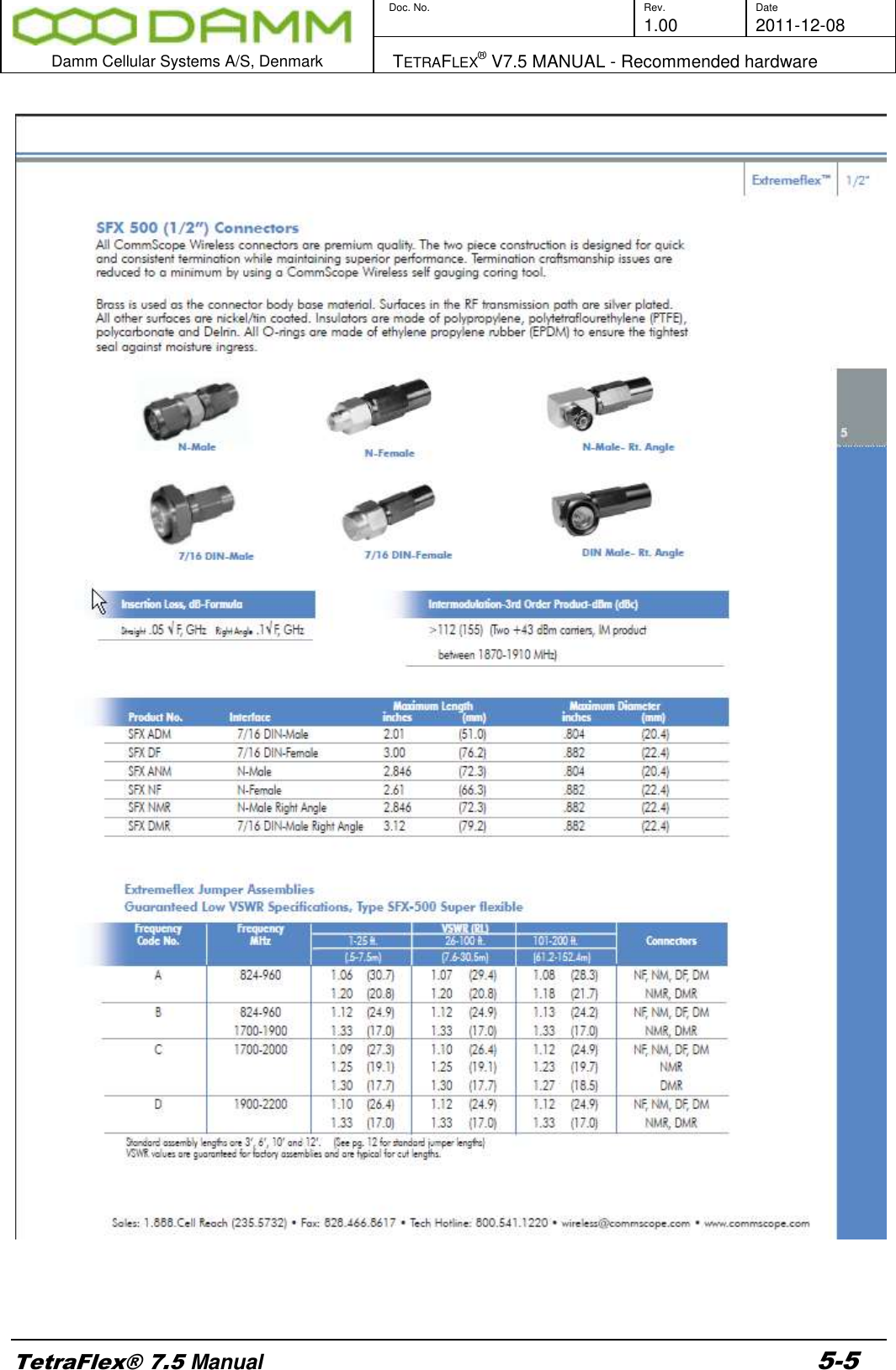
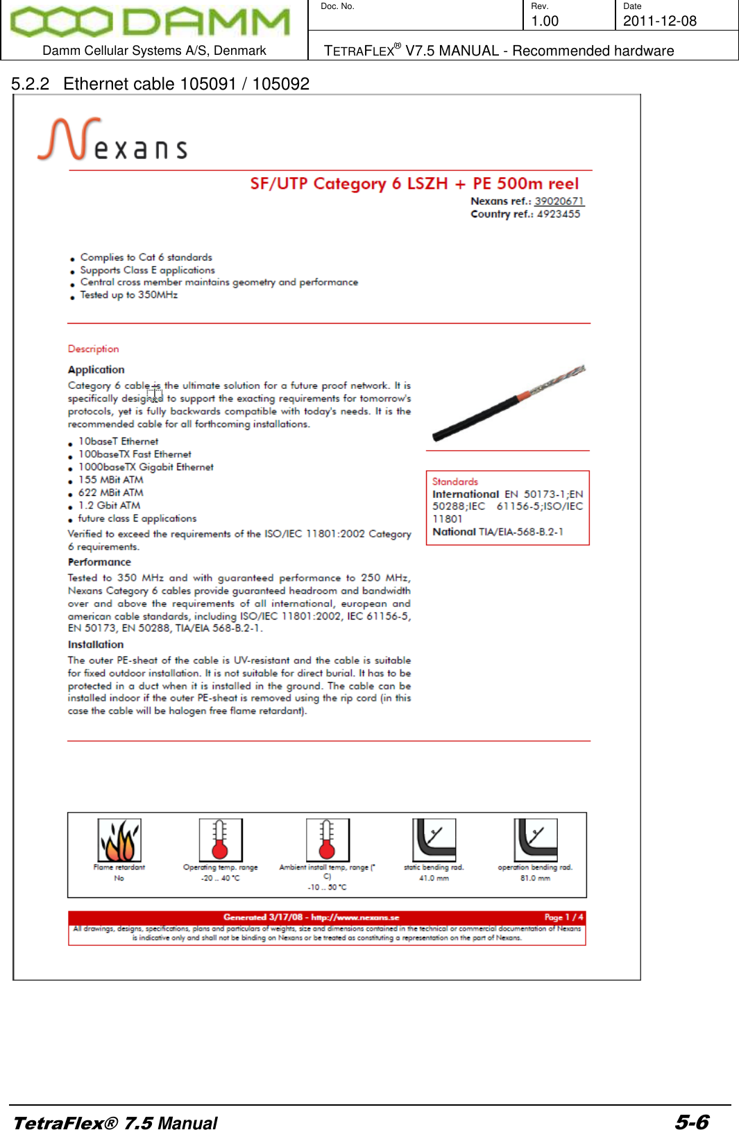
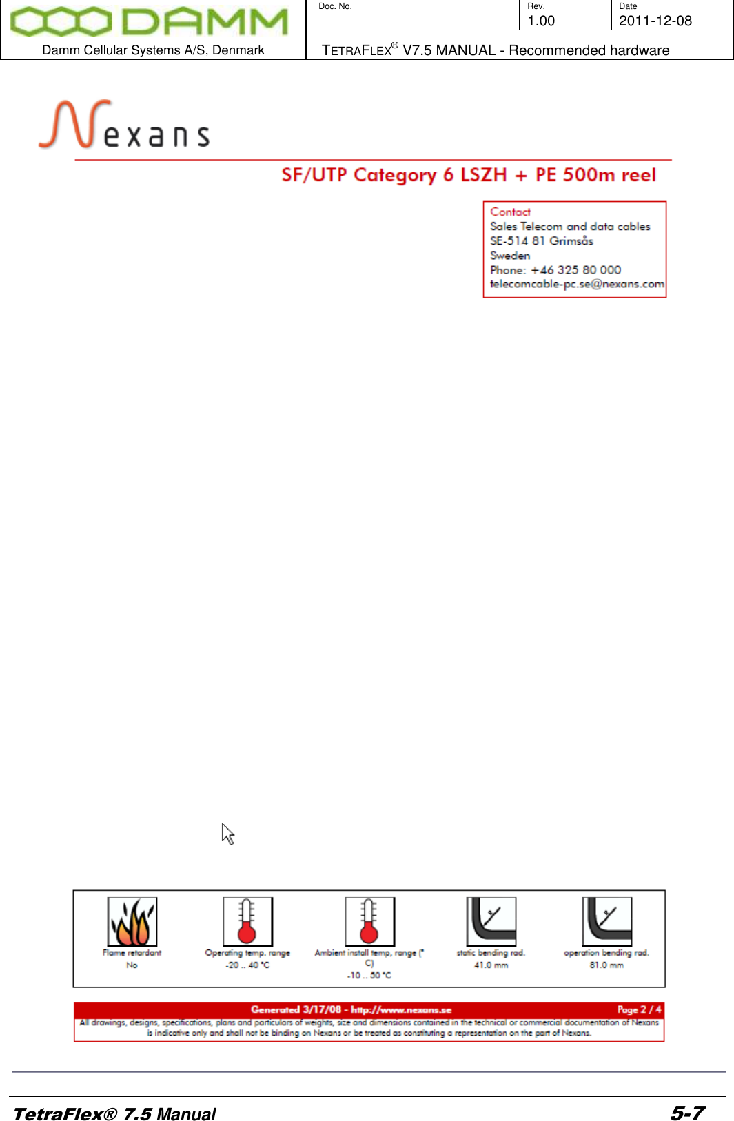
User Manual - 4
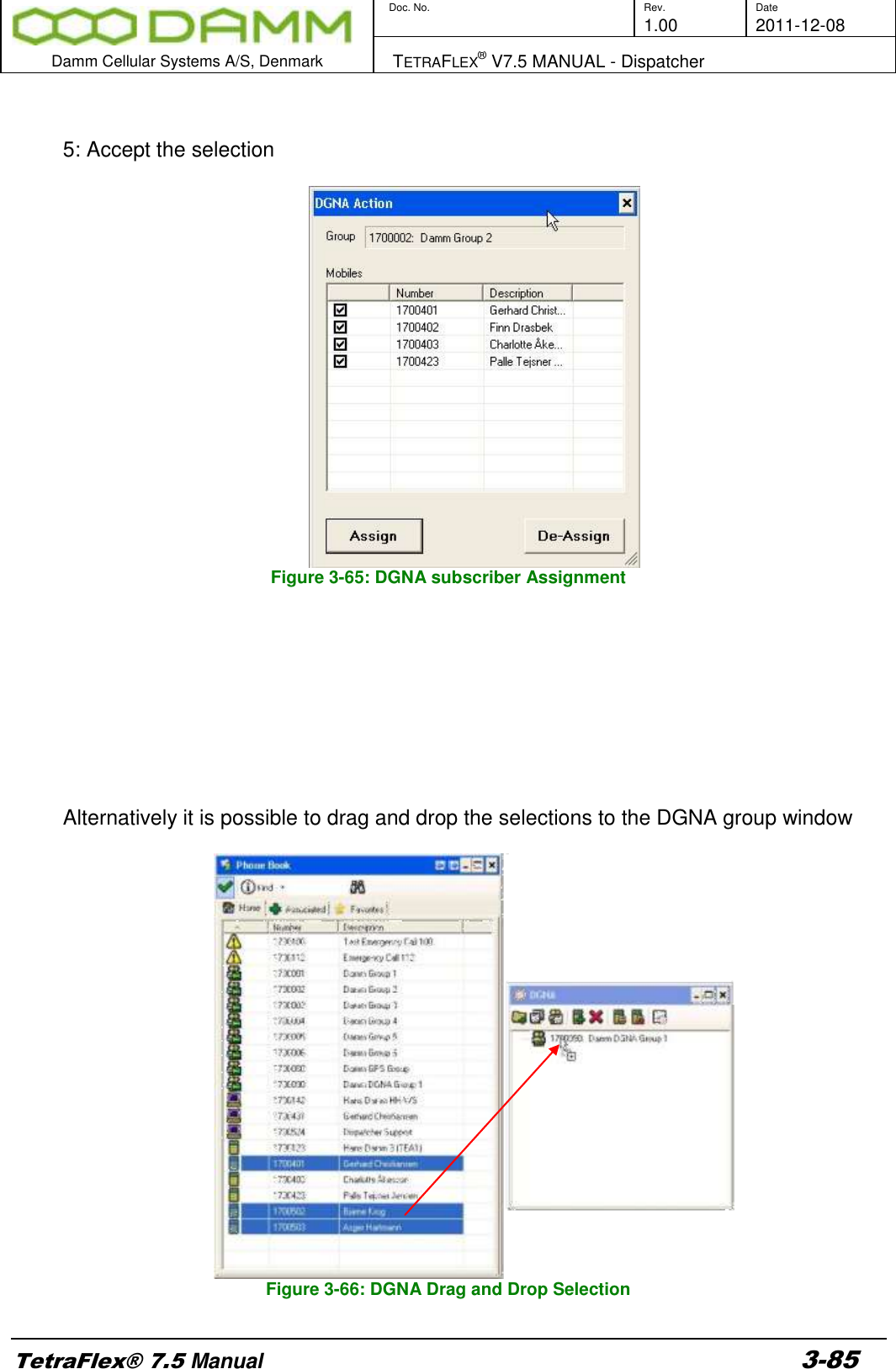
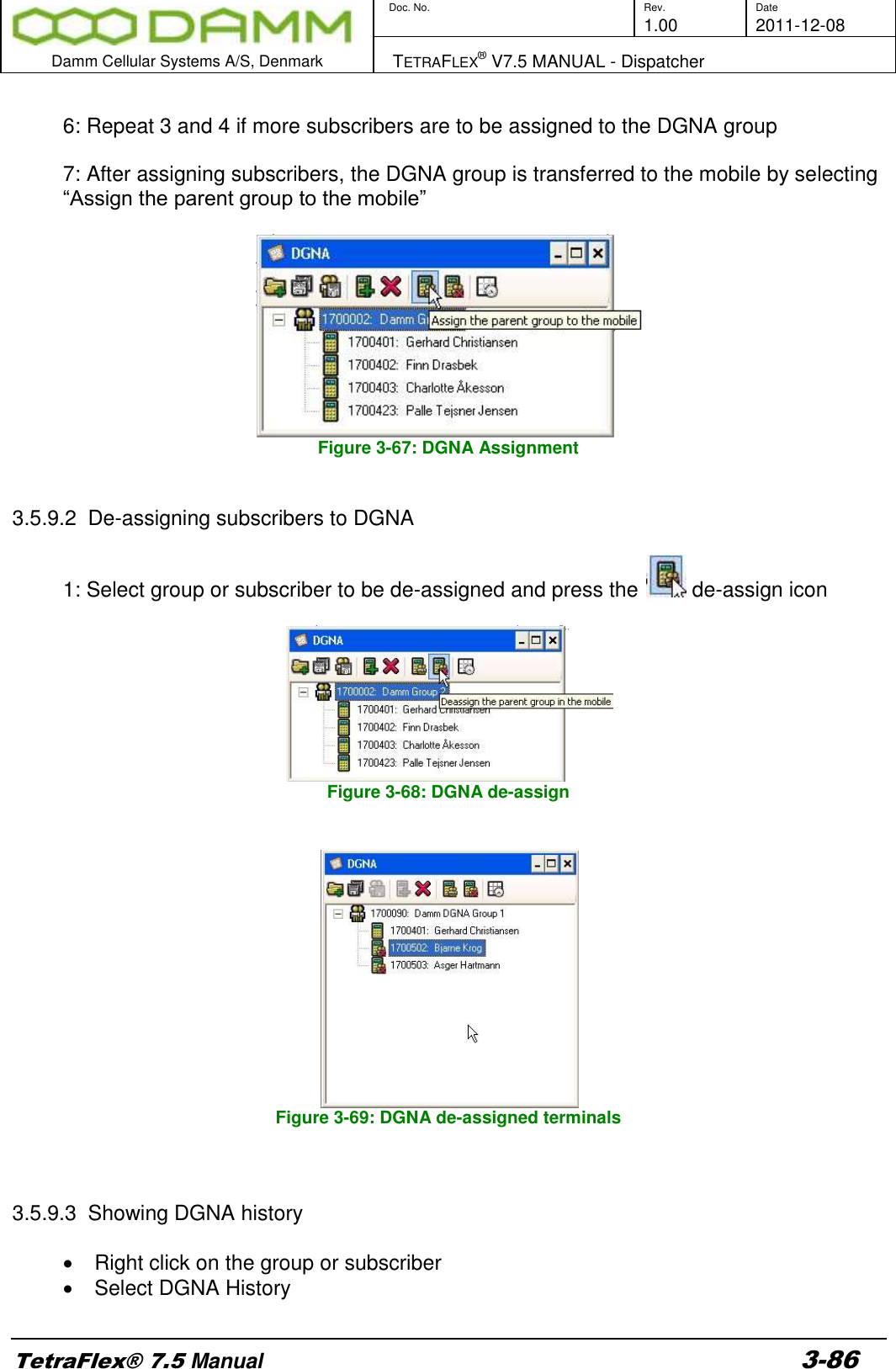
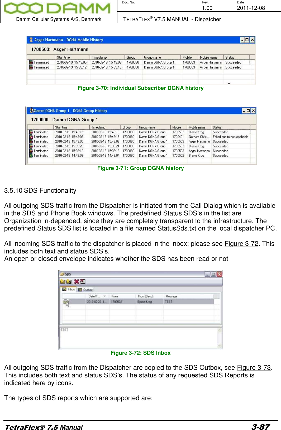
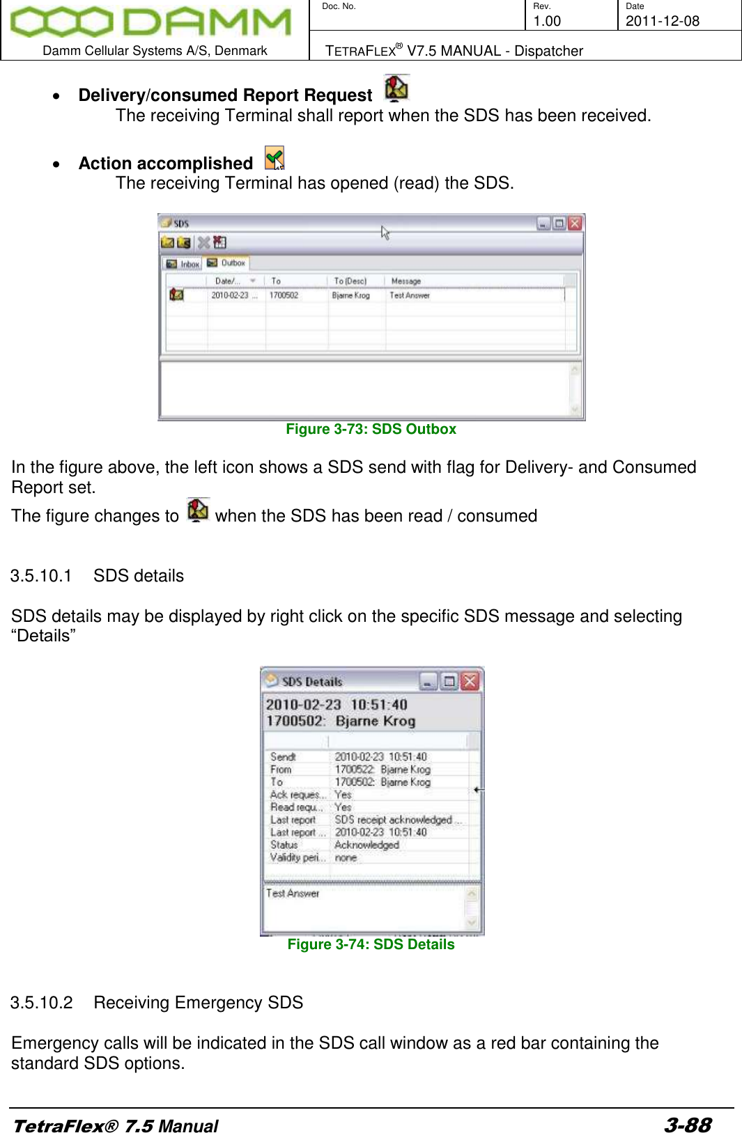
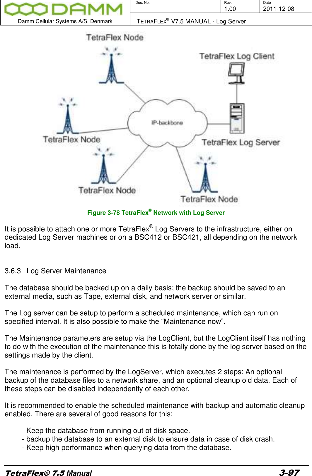
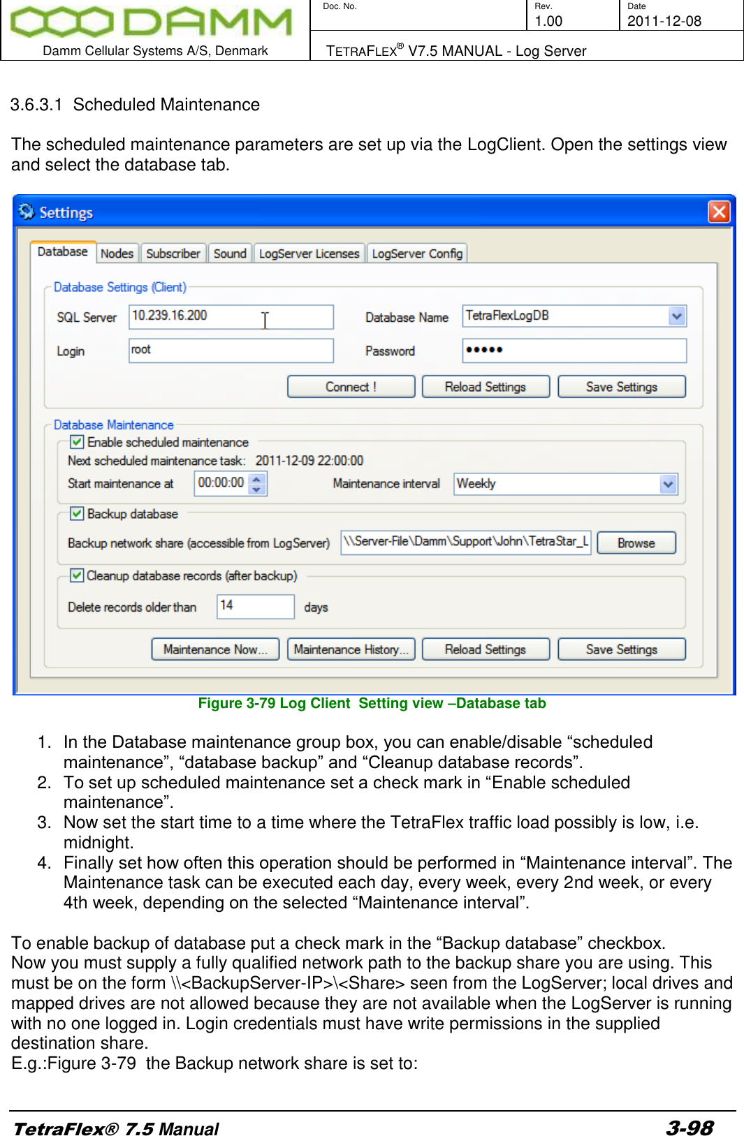
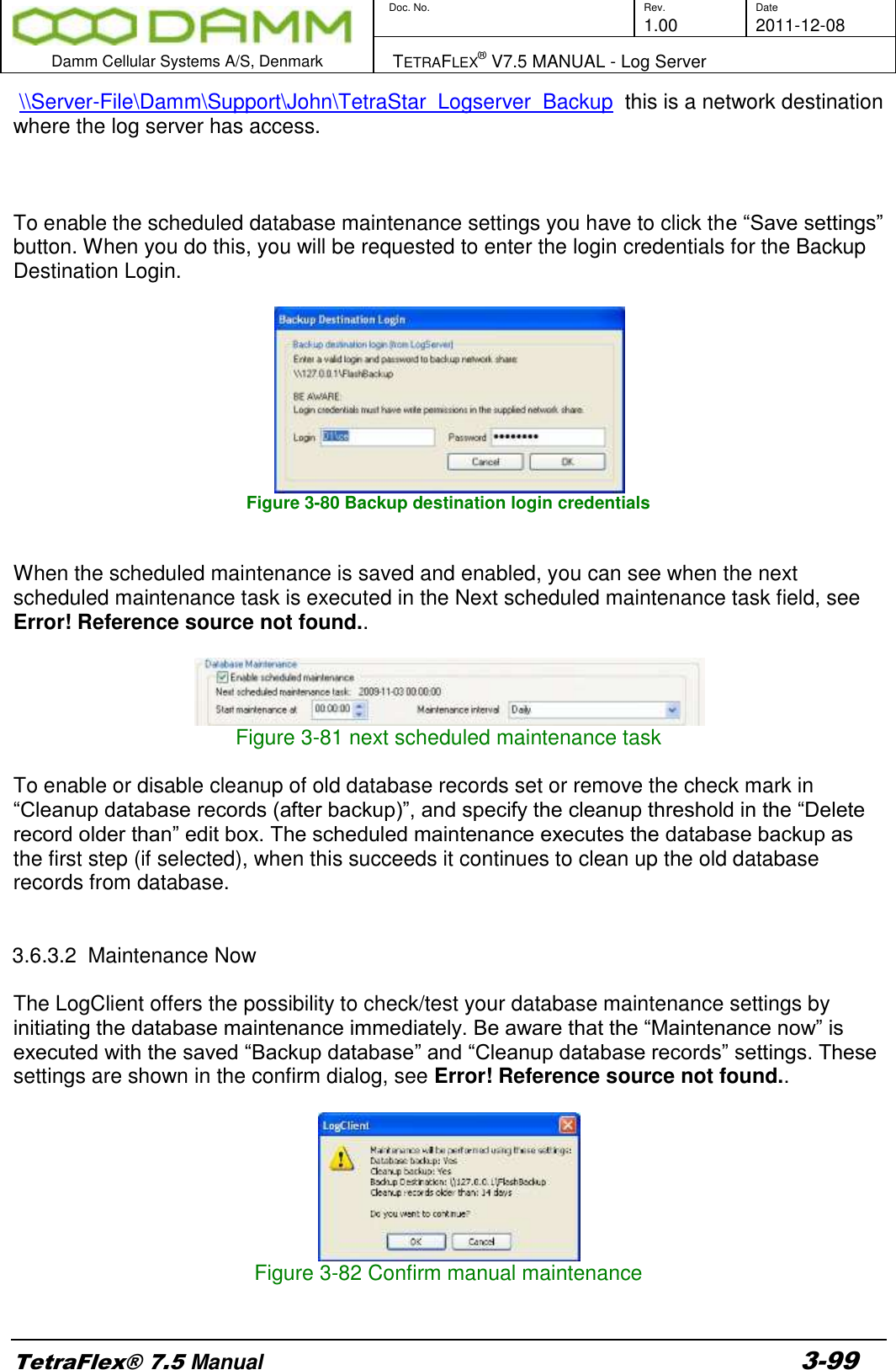
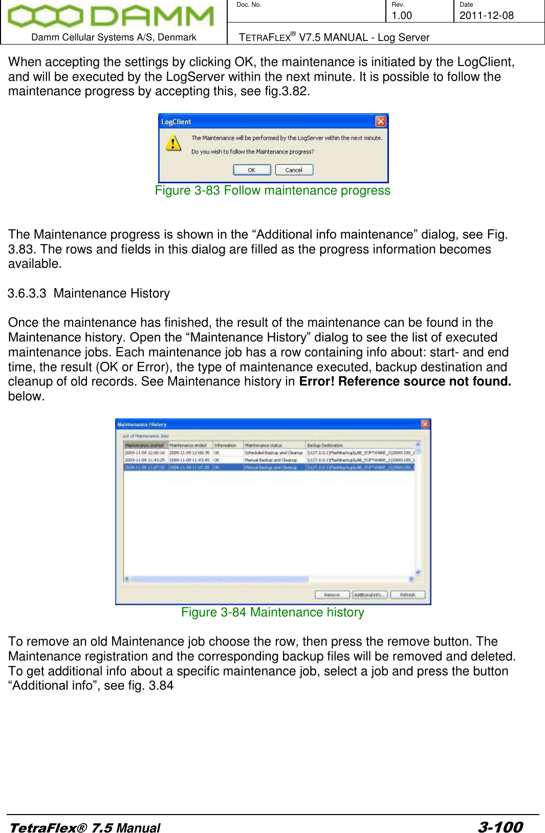
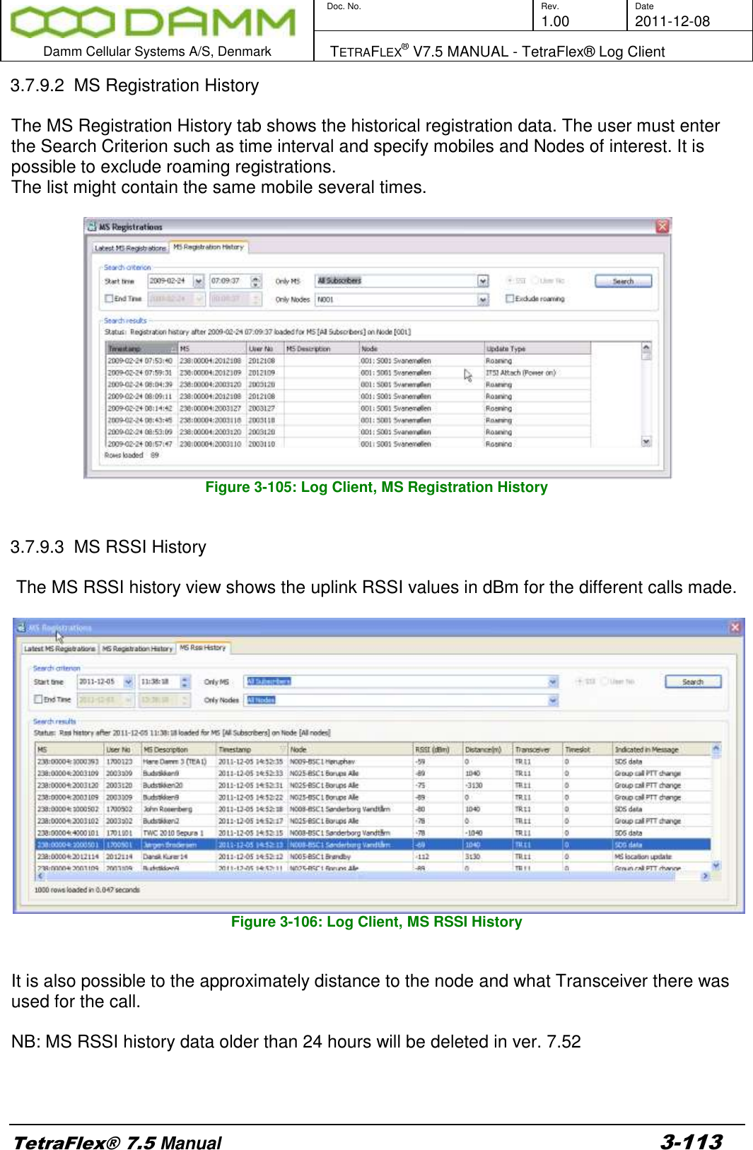
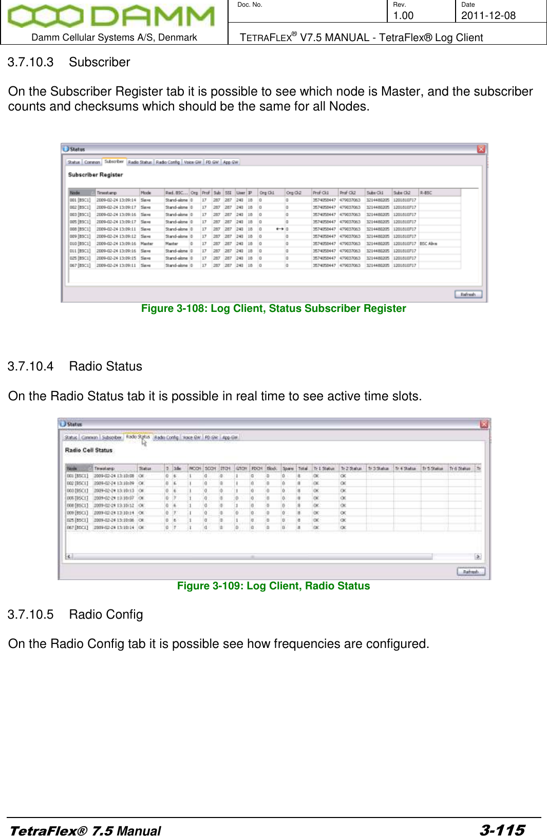
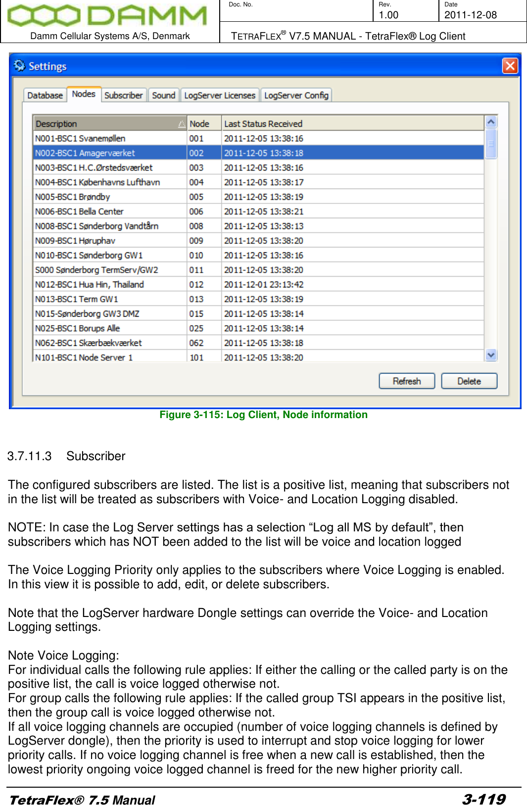
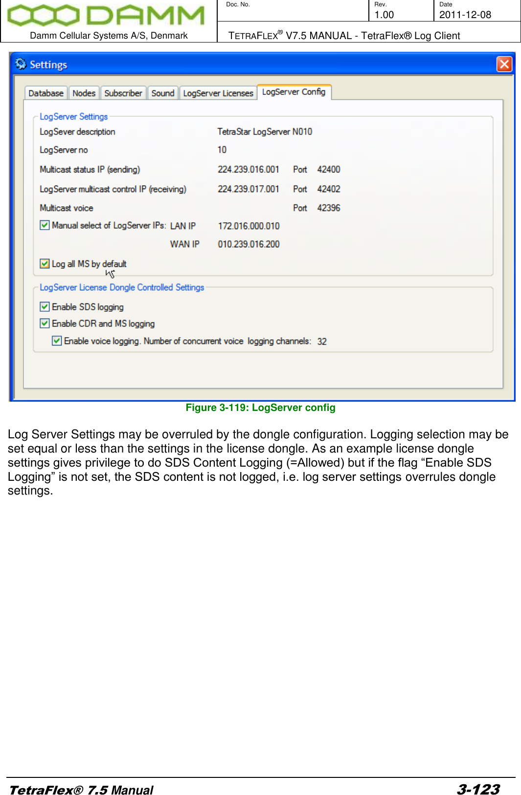
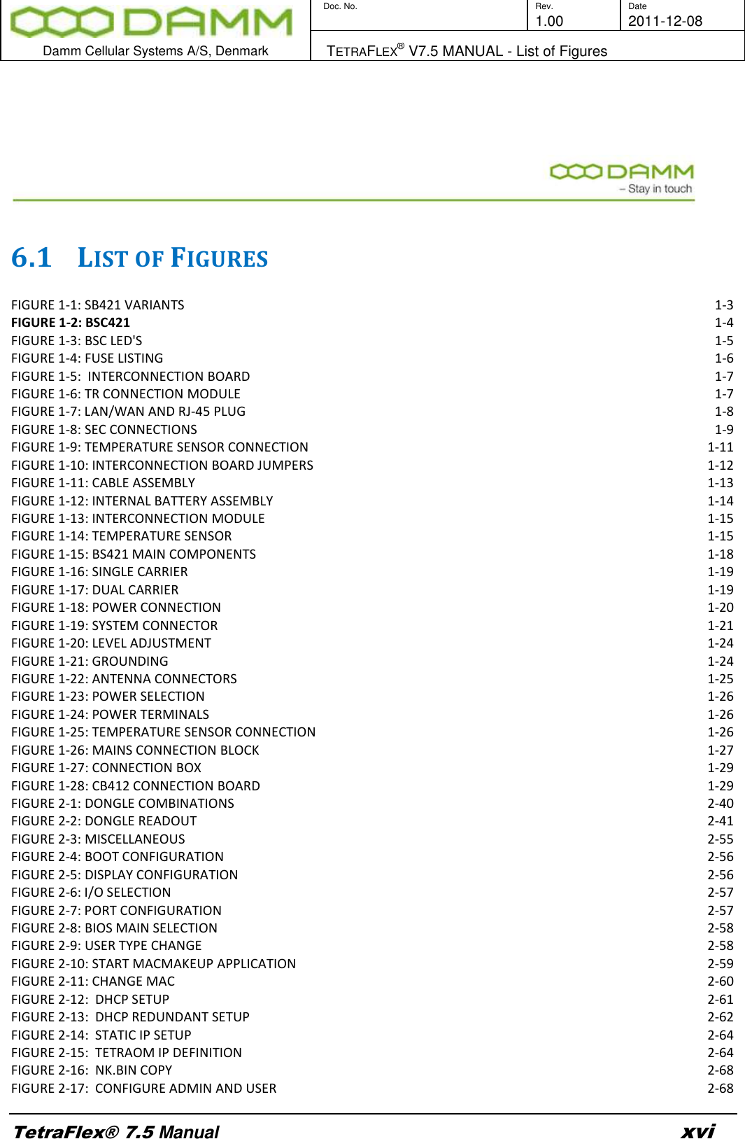
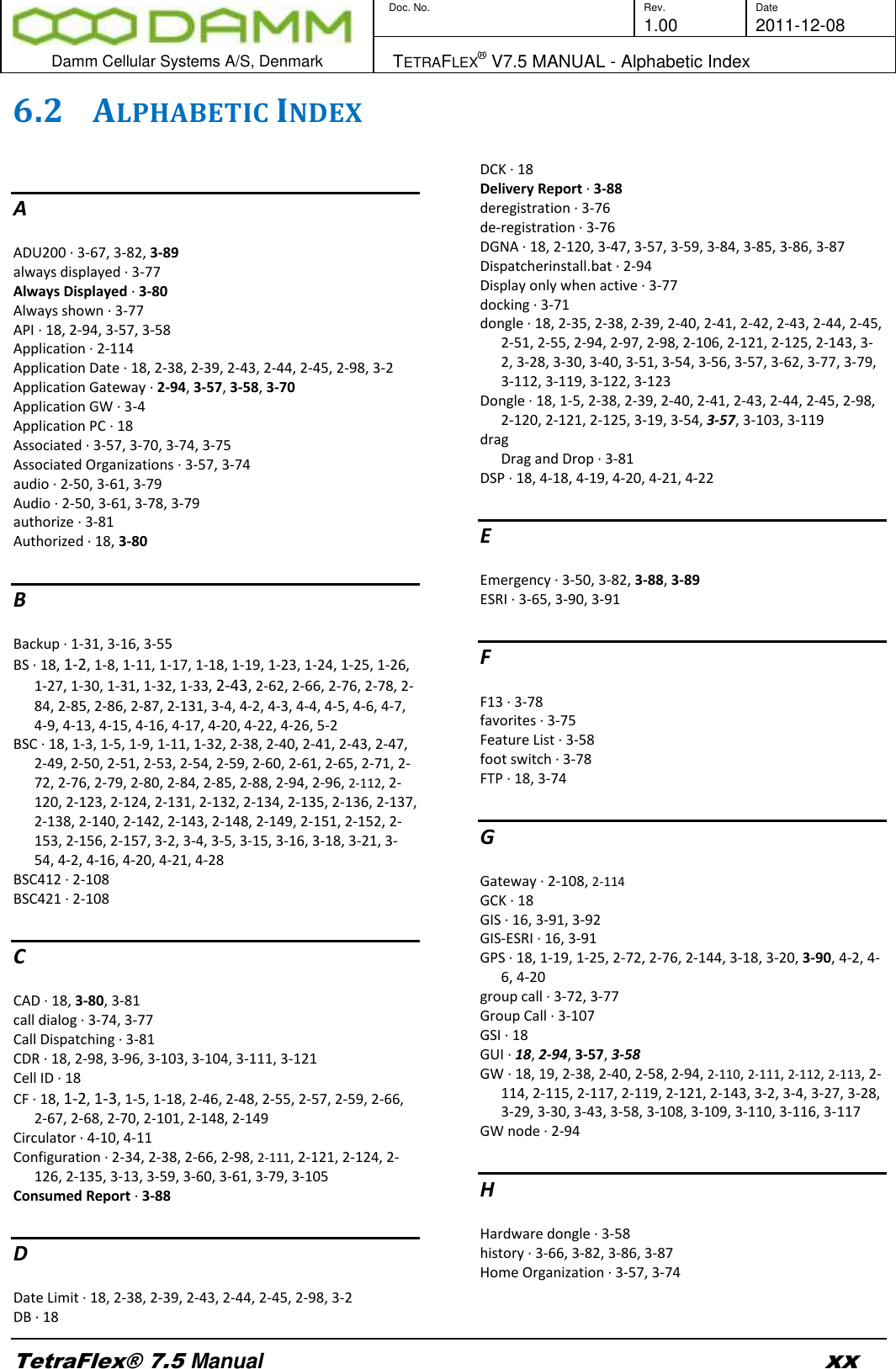
![Doc. No. Rev. Date 1.00 2011-12-08 Damm Cellular Systems A/S, Denmark TETRAFLEX® V7.5 MANUAL - TetraFlex® Log Client TetraFlex® 7.5 Manual 3-114 3.7.10 Status View The status view shows the latest received Status messages of the TetraFlex® Node. Each TetraFlex® node in the network reports its status on regular interval (default interval is 10 seconds). This means that the Status view should always have status messages no older than the interval. On each status tab the nodes in the TetraFlex® network are listed including the reception timestamp of the TetrtaFlexLogServer and their latest status. The Status tab gives an overview of the nodes and their status. Each Status generally has these states: Status Table Status type Description OK Everything in perfect order. Warning [L1] Level 1 warning, informational only. Alarm [L2] Level 2 Alarm, reduced functionality of component. Blocked [L3] Level 3 Blocking Alarm, dropout of component. Start-up The component is starting up. Not Alive The component is not responding. [BLANK] The component is not configured on this node. The list can be refreshed manually by pressing Refresh. 3.7.10.1 Status The Status tab shown below gives an overview of the status window. The view is essential the same as shown in the Network Management, so refer to the Network Management Manual for detailed description of the tabs Figure 3-107: Log Client, Status view 3.7.10.2 Common On the Common tab it is possible to see the Repetition time interval, which the node uses for sending its status message.](https://usermanual.wiki/Damm-Cellular-Systems-A-S/104012.User-Manual-4/User-Guide-1739426-Page-31.png)