Designated Parking 103 MYSPOT REMOTE CONTROLLED PARKING BARRIER-TX User Manual Installation Manual V17 pub
Designated Parking Corp. MYSPOT REMOTE CONTROLLED PARKING BARRIER-TX Installation Manual V17 pub
UserManual.wiki
>
Designated Parking
>
103 User Manual
instruction manual
Navigation menu
Upload a User Manual
Namespaces
Wiki Guide
HTML
PDF
Info
Views
User Manual
Discussion / Help
Navigation
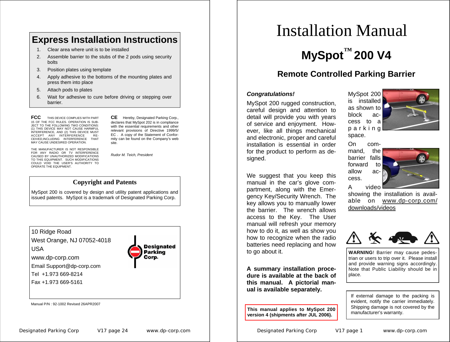
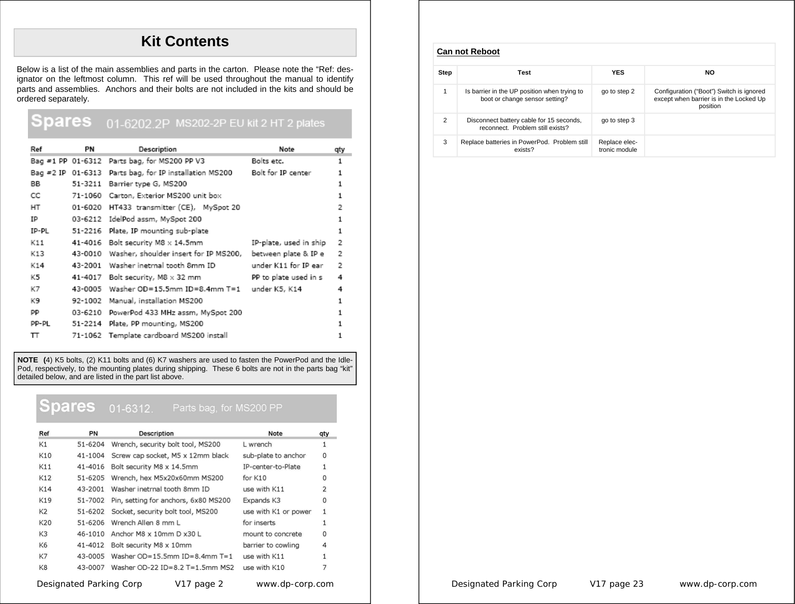
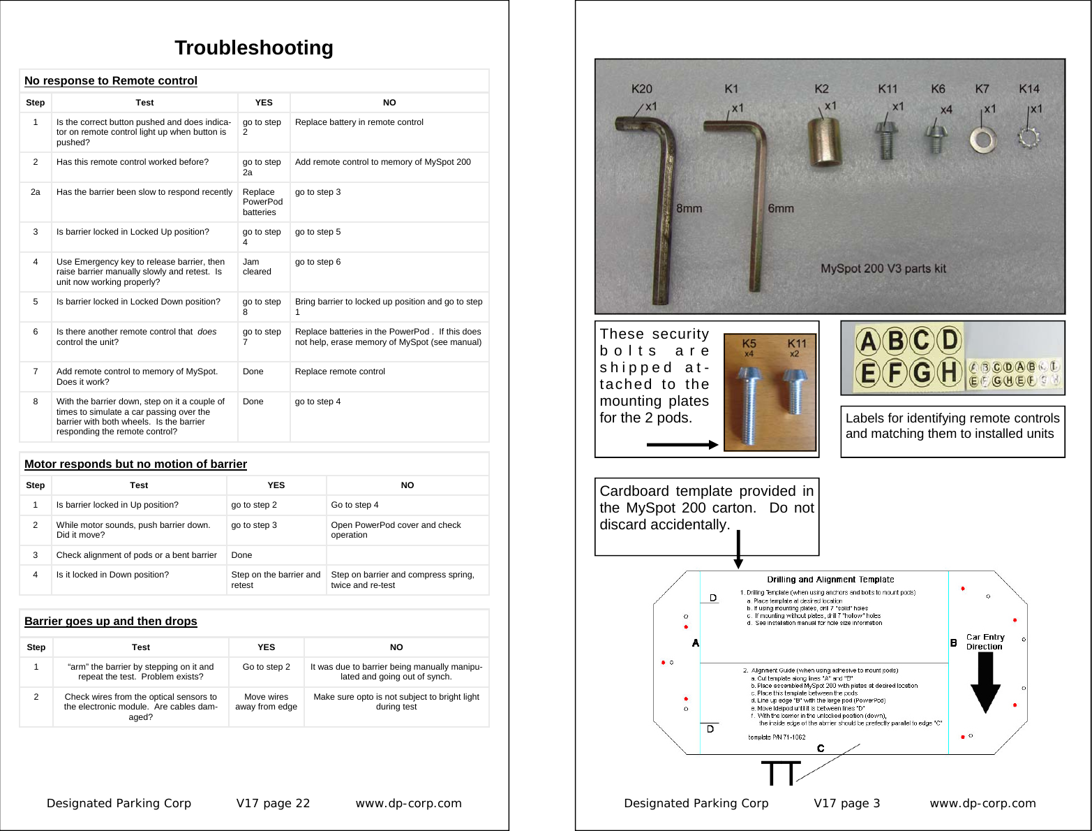
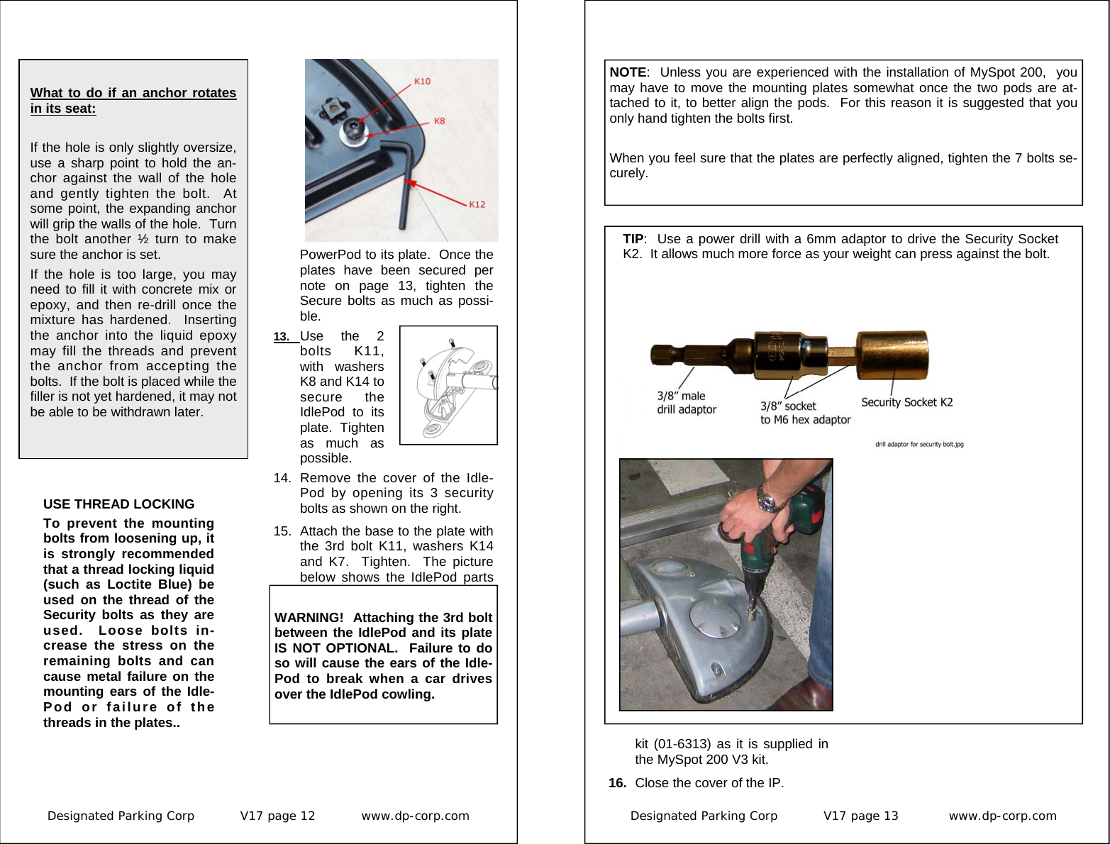
![Designated Parking Corp V17 page 8 www.dp-corp.com Barrier Clearance The front (leading) edge of the bar-rier must be able to travel 3” [8 cm] (from its Unlocked position) before it hits the ground. A rise in the road-way anywhere along the contact point between the barrier and the ground will interfere with this full range of motion. To check the surface, place the barrier up-side-down on the ground. Observe any height irregularities. If the road-way is lower in between the two ends of the barrier, there is no problem. If the roadway at even one point is 7 mm (¼”) higher, move the barrier towards the front or the rear of the space until a better location is found. If the rise in the middle is unavoid-able, you may have to raise one or both pods using a suitable plastic or metal plate. The use of wood or plywood is not recommended as it will rot. 3: Assemble Barrier Prior to the mounting of MySpot 200, the barrier needs to be assembled to complete the assembly of the device. This will self-align the two pods. 1. Make sure that the stub on the PowerPod is in the Locked Up position. (See inset for instruc-tions how to manually bring the shaft to the Locked Up position if necessary.) 2. Rotate the stub on the IdlePod until it too is in the Locked up position. 3. Slide the barrier over the stub of the PowerPod. The grooved surface of the barrier should be facing back, away from the en-trance to the parking space. The reflective yellow label on the front of the barrier should face the entrance to the parking space. 4. Make sure that the holes on the barrier line up with the threaded holes in the stub. 5. S e c u r e the barrier to the stub using 2 washers K14 and 2 short se-curity bolts K6. 6. Repeat the process for the Idle-Pod side and secure the barrier to the stub using washers K14 and security bolts K6 . Beware of uneven surface Designated Parking Corp V17 page 17 www.dp-corp.com Once the first remote control has been added (“programmed” or “paired”) to the authorized list in the radio receiver in the PowerPod per section 6, additional remote controls (up to a total of 15) can be pro-grammed. Adding Remote controls 1. Make sure that any barrier in the vicinity that is still unpro-grammed is placed in the Unlocked posi-tion. 2. Place the barrier in the Locked Up position. Prop the barrier with your leg so that the barrier will not fall when activated. 3. Hold the authorized remote con-trol (“A”) in one hand, and the new one (“B”) in the other. 4. The sequence as explained be-low is A-A-B-A. 5. Press the previously pro-grammed button(s) on the au-thorized A remote control. The motor will whirl. The green indi-cator on the HT remote control will stay lit for 2 seconds. If the remote control is set to a 2-button mode, press the two keys in sequence to get the motor to whirl. 6. Two seconds after the motor stopped, press the authorized key A again. The motor should sound again. 7. Two seconds after the motor stopped, press the desired but-ton(s) on the new (“B”) remote control. The green indicator on it will turn on for 2 seconds. In the case of 2-button setting, press the same key sequence on the new remote control as you do on the authorized remote control. 8. After the green indicator on the new remote control turns off, wait 2 seconds then press the First Remote control seconds to acknowledge a suc-cessful “reboot”. 6. The unit has been returned to the factory setting. To program the first remote control, just acti-vate it. 7. Connect the antenna and close the cover. Once the MySpot has been erased, it will learn the first remote control it “sees” as a valid remote control. 1. Place the barrier in the Locked Up position. 2. Press the button, or sequence of buttons (if the HT is in the two-button mode), on the remote control that you wish to pair with the barrier. 3. The motor should whirl and the barrier should fall. The remote control has now been paired with the barrier.](https://usermanual.wiki/Designated-Parking/103/User-Guide-845141-Page-8.png)