Digitool Instruments GC132926 Hot air balloon wire less temp gauge User Manual 565433
Digitool Instruments AB Hot air balloon wire less temp gauge 565433
Contents
- 1. transmitter dbitx1 user manual
- 2. receiver dbi002 user manual
- 3. transmitter dbitx2 user manual
receiver dbi002 user manual

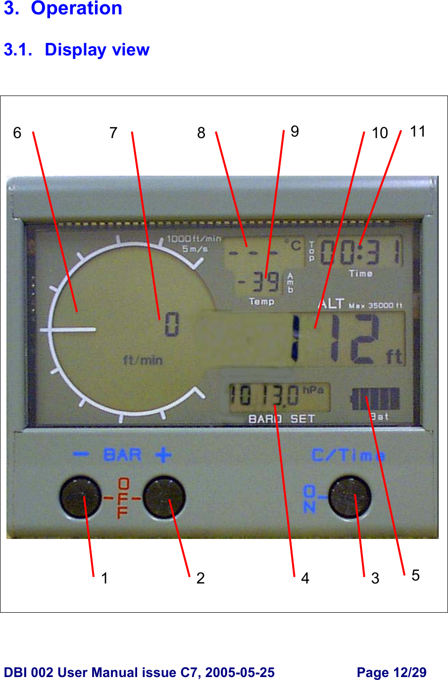
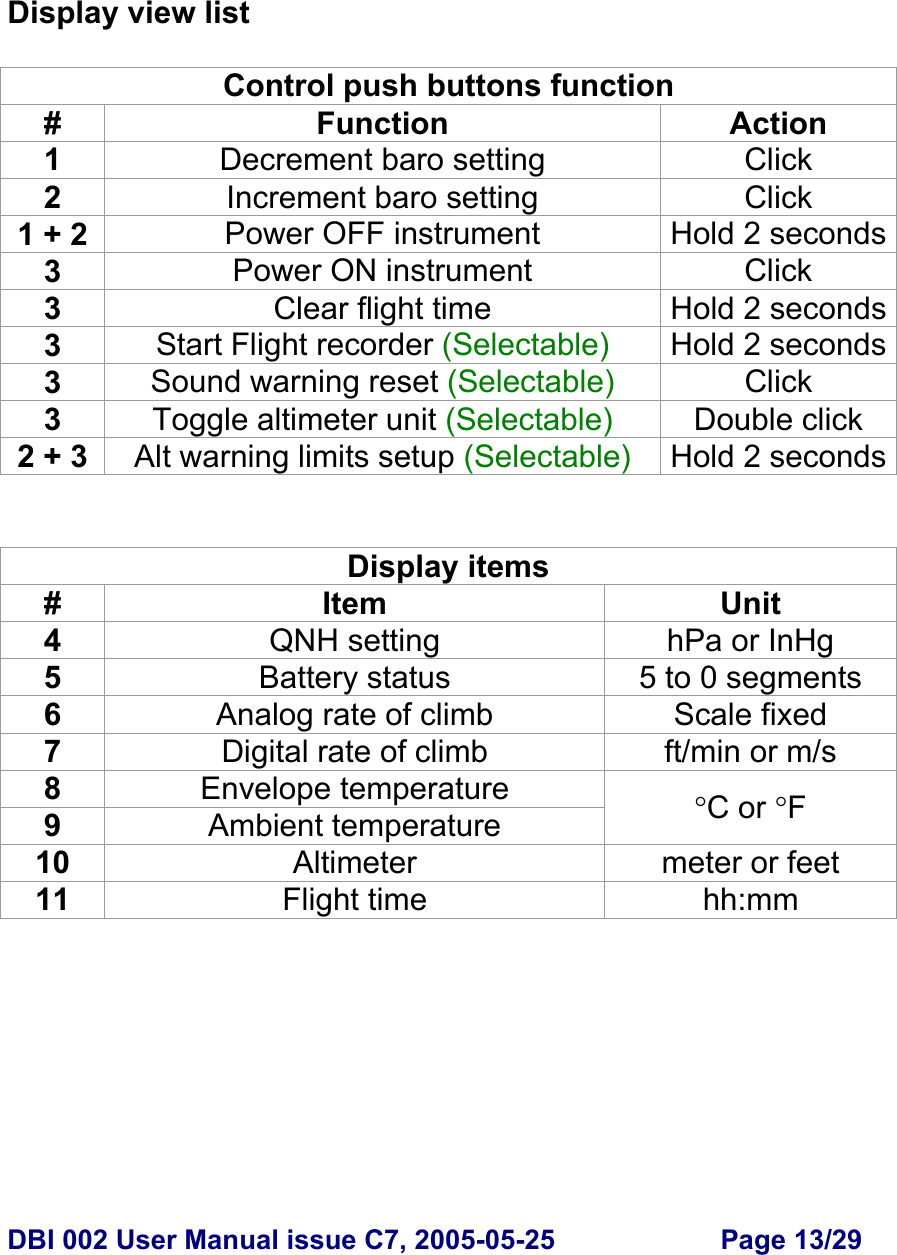
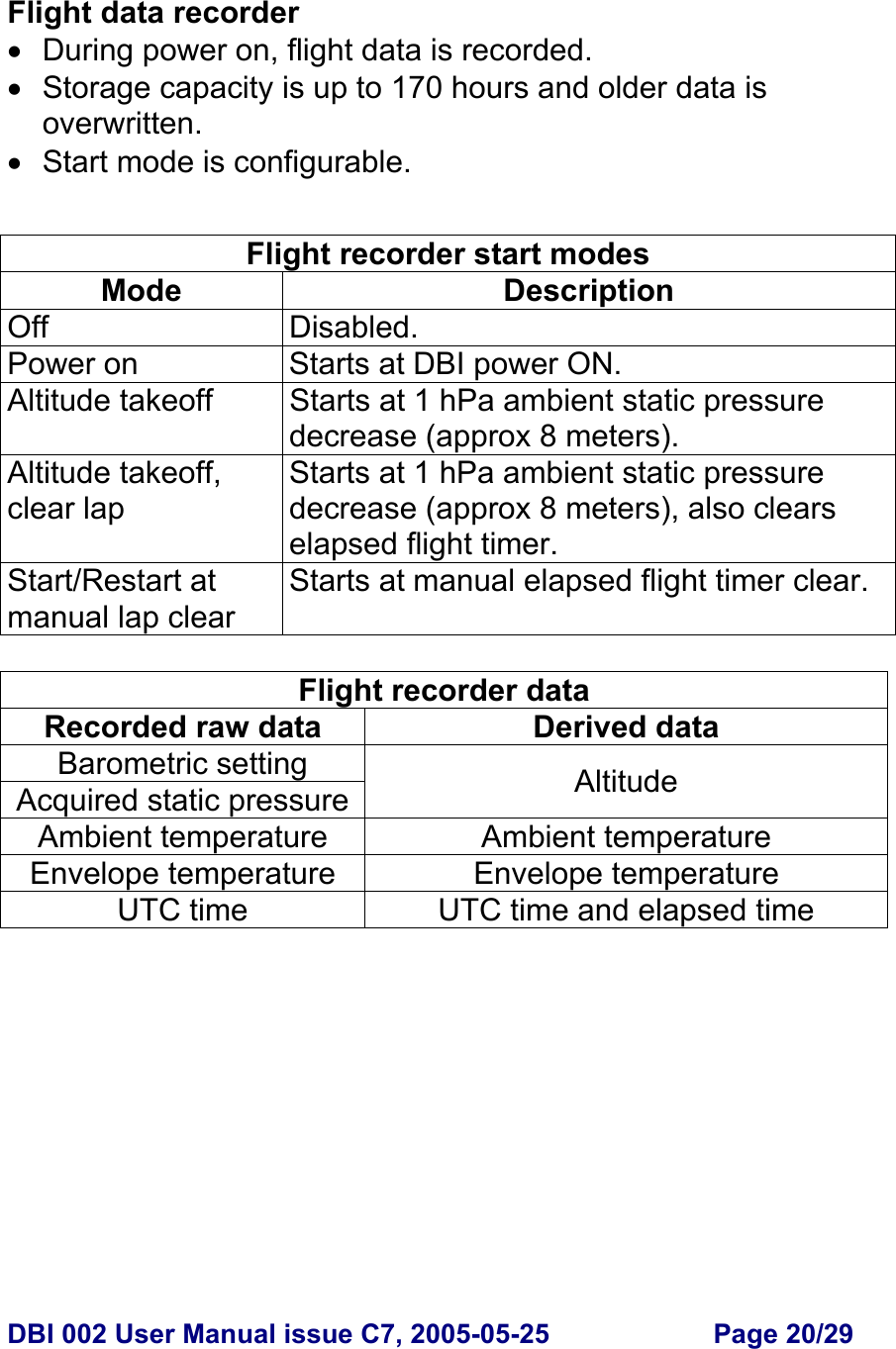
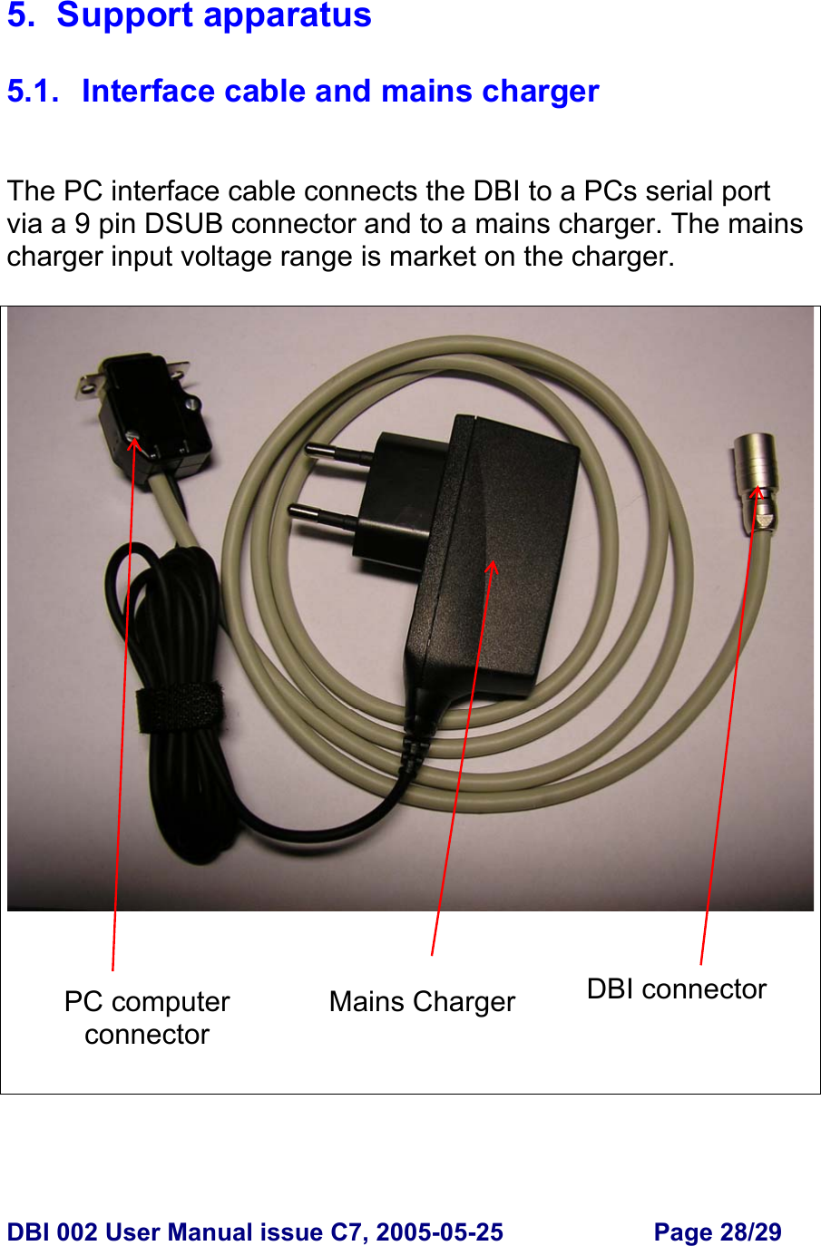
![DBI 002 User Manual issue C7, 2005-05-25 Page 16/29 3.4. In flight operating functions Power On / Off • The DBI is powered ON by pressing the C/Time push button. This button is also marked ON. • The DBI is powered OFF by pressing the two BAR buttons simultaneously for 2 seconds. These two buttons are also marked OFF. • Auto power off enabled: The DBI powers off automatically when acquired static pressure has changed less than 0.5 hPa (4 meters altitude change at 1013 hPa) during 30 seconds during a 30 minutes time interval. Prior to the auto power off, the altitude display digits shows “OFF”. Altimeter • Altitude is displayed with 5 digits. • Displayed Metric range is -9999 to 99999 meter. 1 meter resolution. • Displayed Imperial range is -9999 to 99999 feet. 1 foot resolution. • Unit static toggle enabled: Double clicking the C/Time push button toggles unit, [m or ft]. • Unit timeout toggle enabled: Double clicking the C/Time push button toggles unit, [m or ft] for 2 seconds.](https://usermanual.wiki/Digitool-Instruments/GC132926.receiver-dbi002-user-manual/User-Guide-565433-Page-16.png)
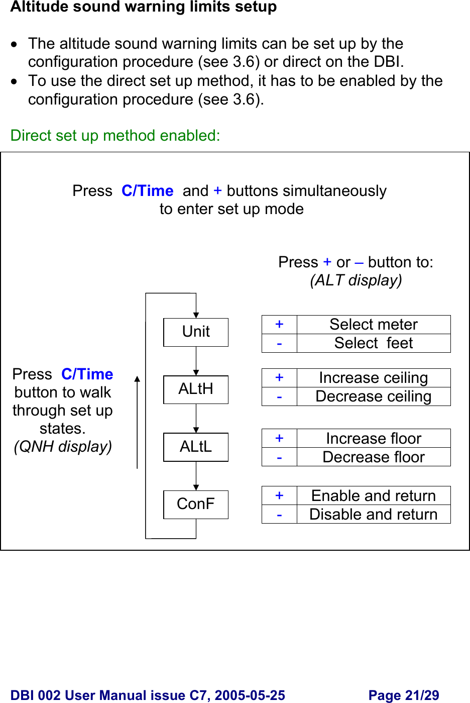
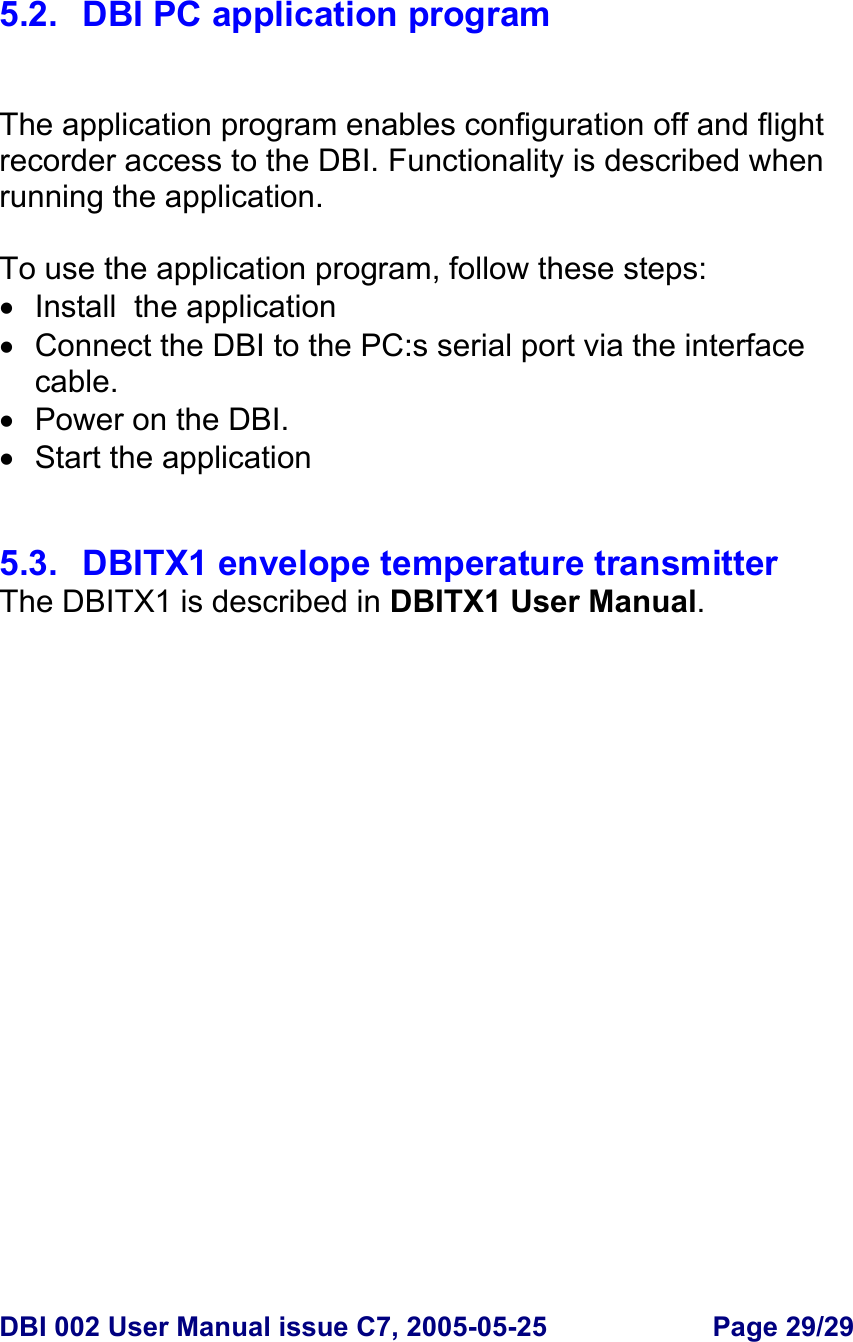
![DBI 002 User Manual issue C7, 2005-05-25 Page 18/29 Acoustic rate of climb (variometer) • Sound signature is separately configured for climb and descend. • Configurable signature: On/Off, Activation threshold, sound repetition interval scale factor. Acoustic altitude high warning • Warning signal is activated on climb transition passing configured altitude high warning limit. • Warning signal is deactivated below altitude high warning limit. • Warning signal is deactivated by pressing the C/Time pushbutton. Acoustic altitude low warning • Warning signal is activated on descend transition passing configured altitude low warning limit. • Warning signal is deactivated above altitude low warning limit. • Warning signal is deactivated by pressing the C/Time pushbutton. Acoustic envelope temperature warning • Warning signal is activated when exceeding configured temperature high warning limit. • Warning signal is deactivated below temperature high warning limit. • Warning signal is deactivated by pressing the C/Time pushbutton. Flight time timer • Elapsed time is displayed. • Range is 00:00 to 99:59 [hour : min]. • Timer is CLEARED on power up. • Timer is CLEARED by pressing the C/Time pushbutton for more than 2 seconds.](https://usermanual.wiki/Digitool-Instruments/GC132926.receiver-dbi002-user-manual/User-Guide-565433-Page-18.png)
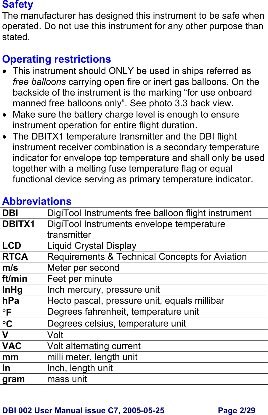
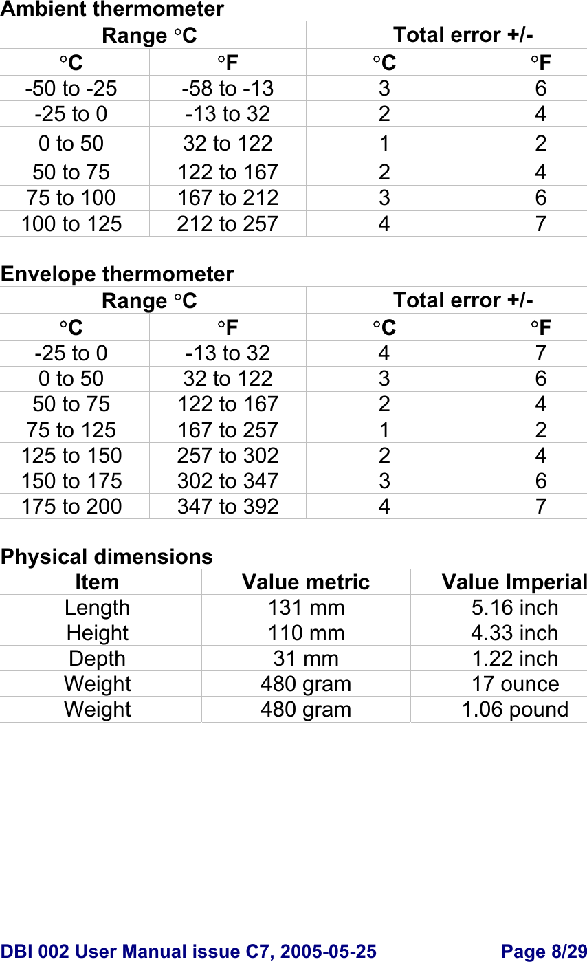
![DBI 002 User Manual issue C7, 2005-05-25 Page 19/29 Ambient thermometer Ambient temperature is displayed with 3 digits. • Imperial range is -60 to 257 °F. • Metric range is -50 to 125 °C. Envelope thermometer The DBI receives envelope temperature from the DBITX1 temperature transmitter (normally located at the top of the envelope). Envelope temperature is displayed with 3 digits. • Imperial range is -13 to 392 °F. • Metric range is -25 to 200 °C. • Loss of data reception is displayed as “---“. • The DBI is configured with identification codes unique for each DBITX1. The DBI can be configured with up to 8 codes. NOTE: Only one DBITX1 shall be active during flight. Battery monitor • Battery charge status is displayed with a battery symbol containing 0 to 5 segments. Segments Continuing operation [hours] 5 50 4 40 3 30 2 20 1 10 0 >1](https://usermanual.wiki/Digitool-Instruments/GC132926.receiver-dbi002-user-manual/User-Guide-565433-Page-19.png)