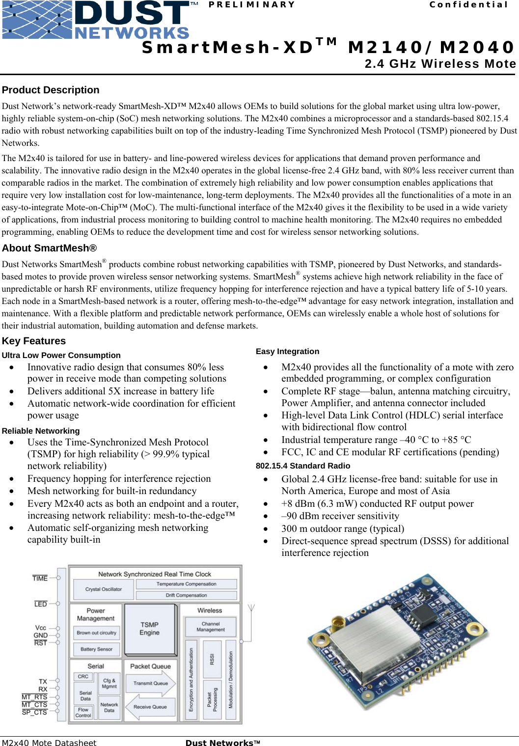
Dust Networks M2140 Smart Mesh Wireless Mote User Manual
Dust Networks, Inc. Smart Mesh Wireless Mote Users Manual
UserManual.wiki
>
Dust Networks
>
M2140 User Manual
Users Manual
Navigation menu
Upload a User Manual
Namespaces
Wiki Guide
HTML
PDF
Info
Views
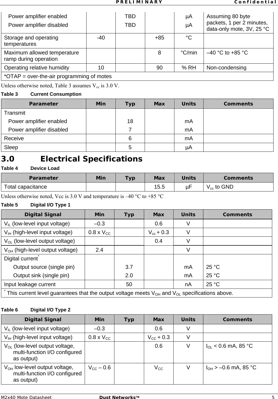
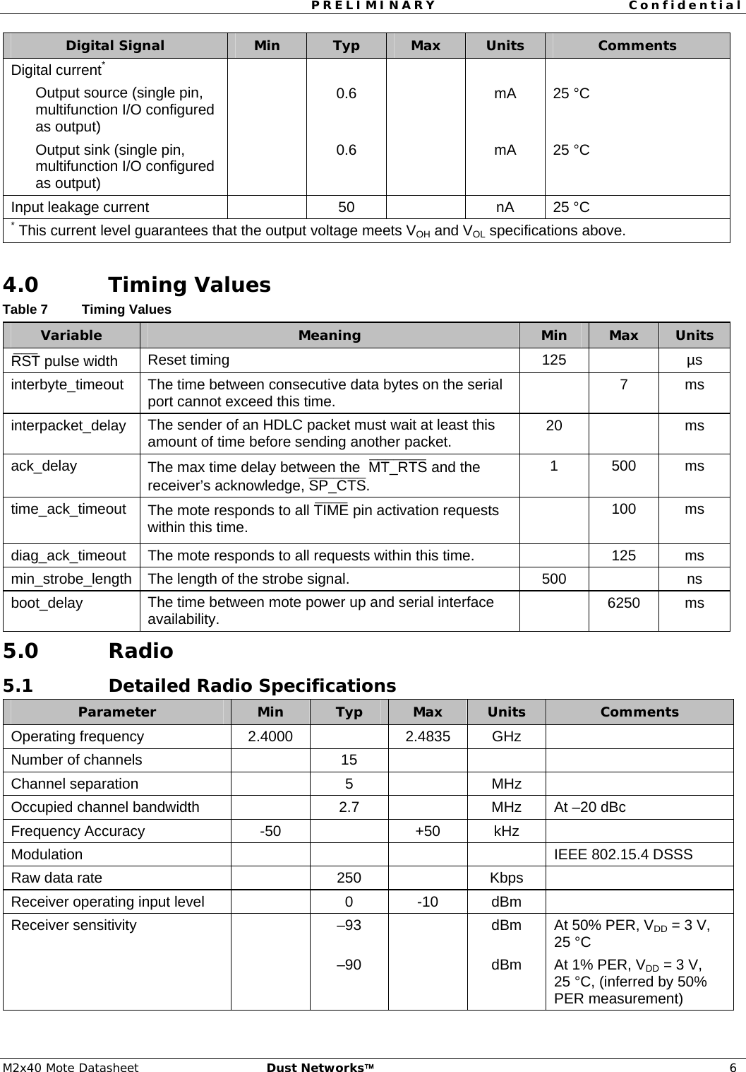
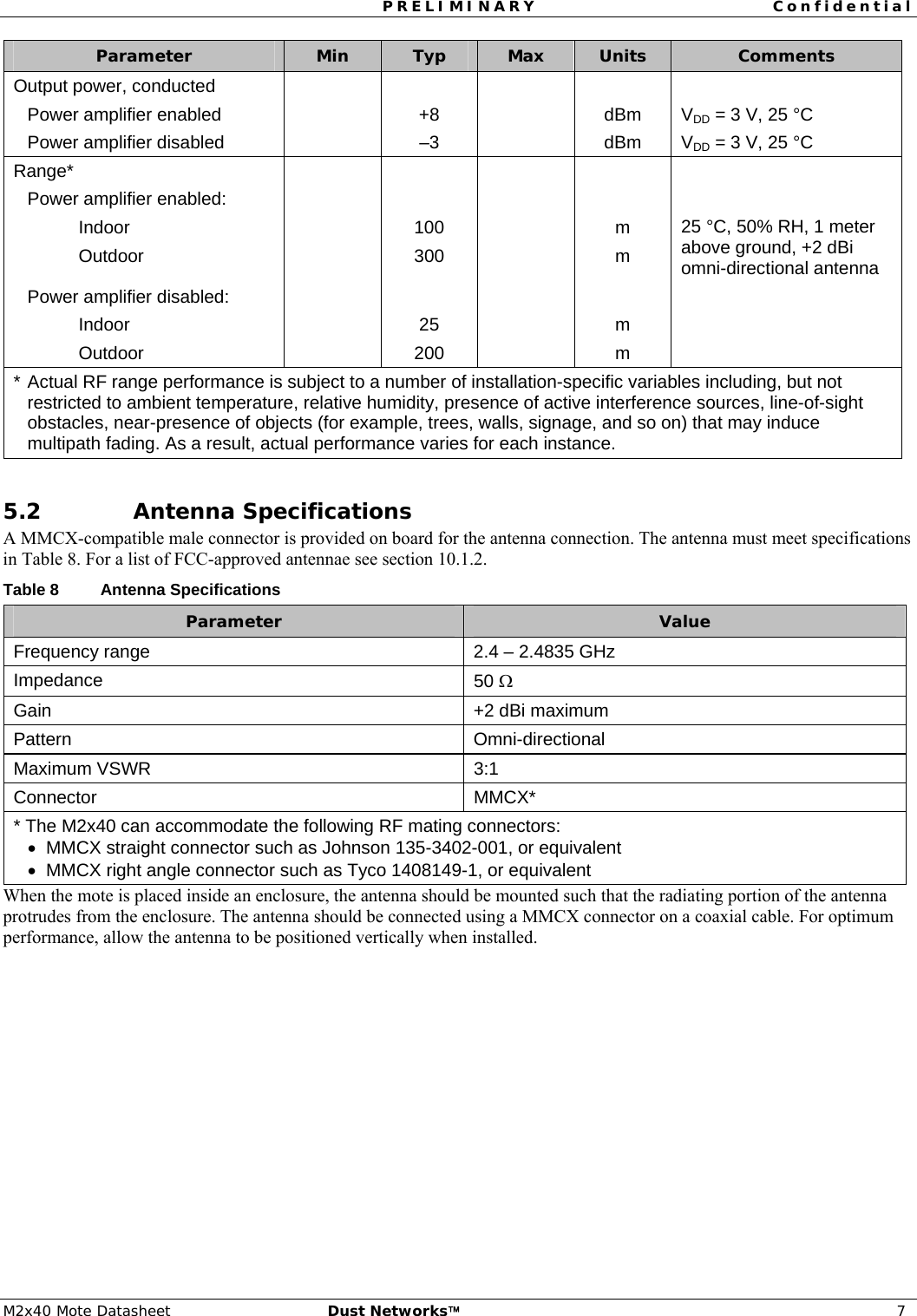
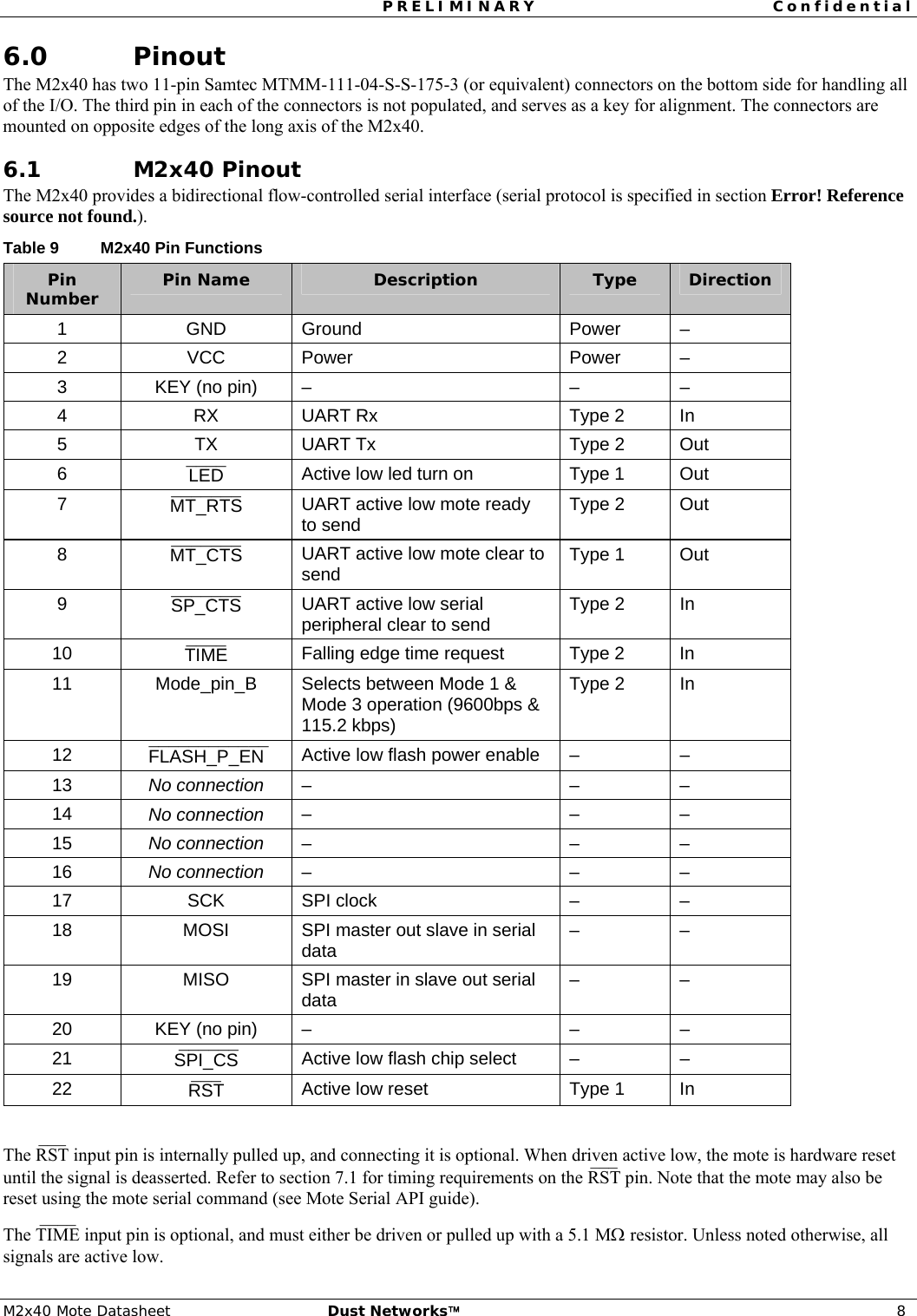
User Manual
Discussion / Help
Navigation