EM Solutions 274H ETHERMUX TDMA User Manual Appendix H
EM Solutions Pty Ltd ETHERMUX TDMA Appendix H
UserManual.wiki
>
EM Solutions
>
274H User Manual
Appendix H TDMA user manual
Navigation menu
Upload a User Manual
Namespaces
Wiki Guide
HTML
PDF
Info
Views
User Manual
Discussion / Help
Navigation
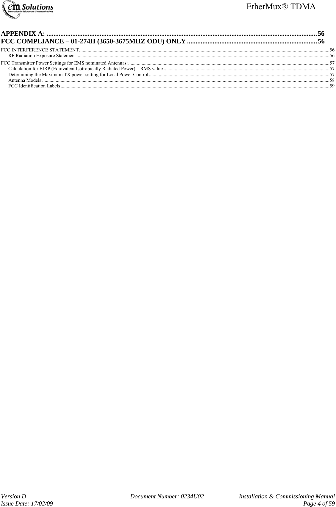
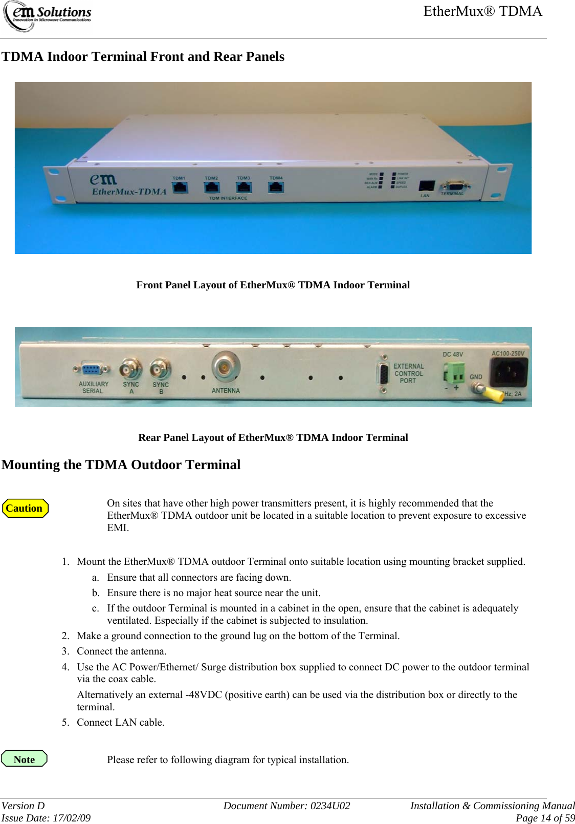
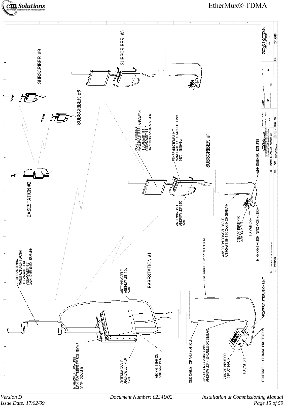
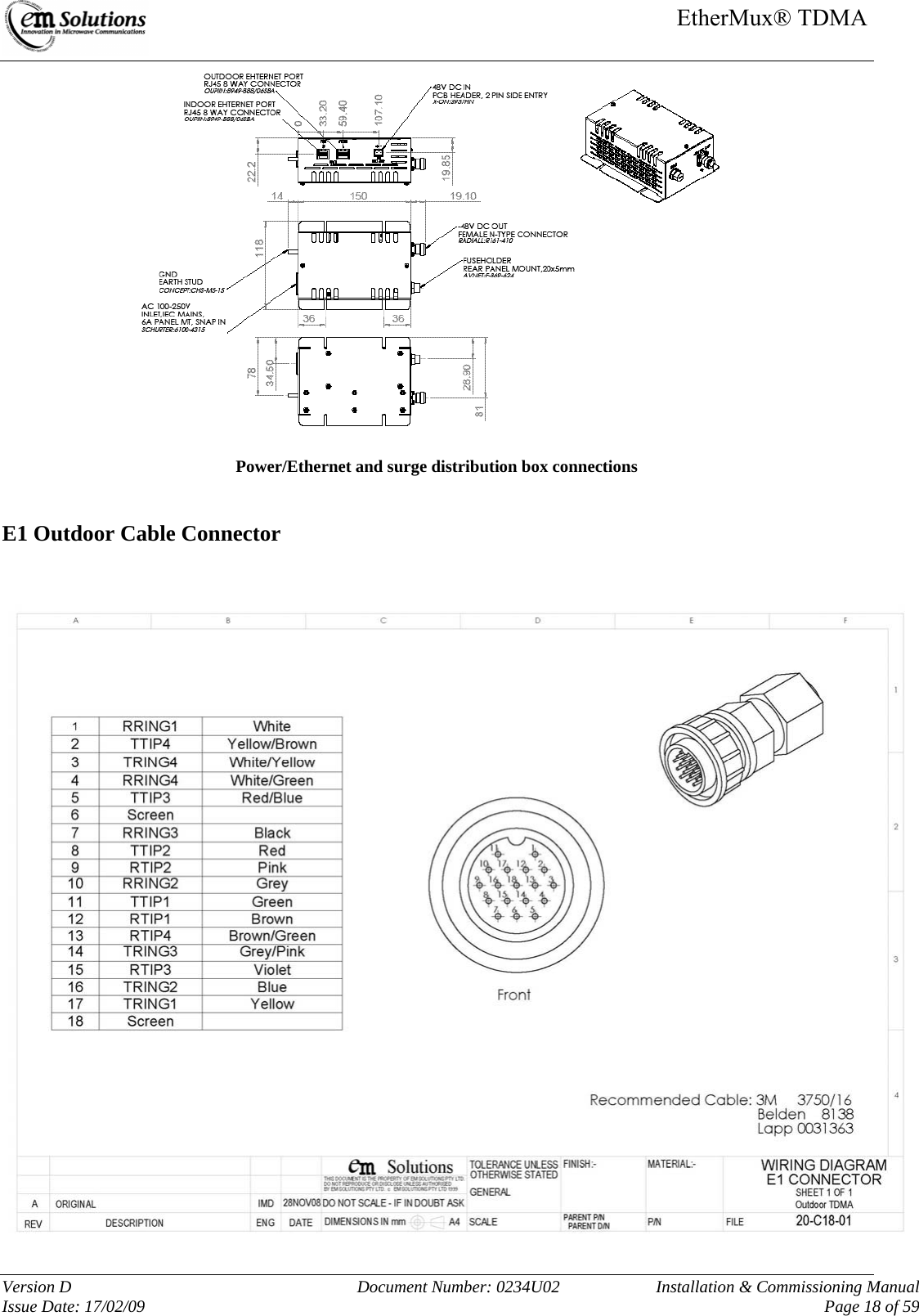

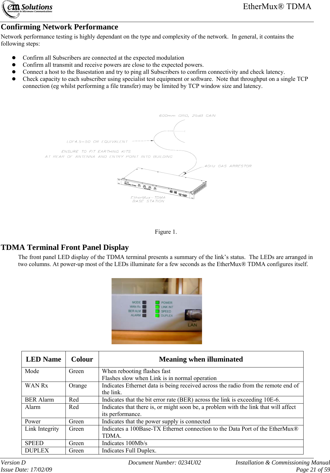
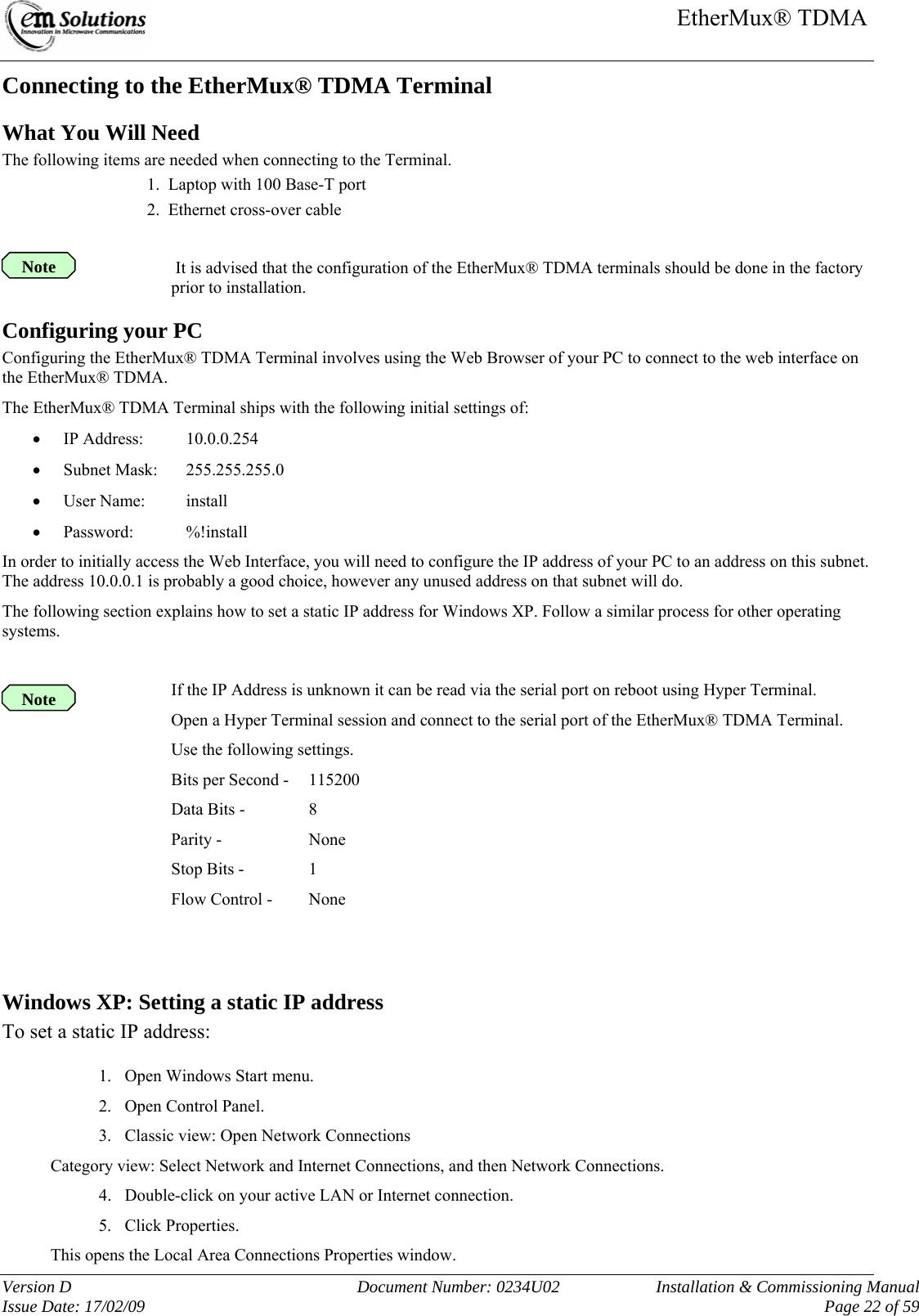
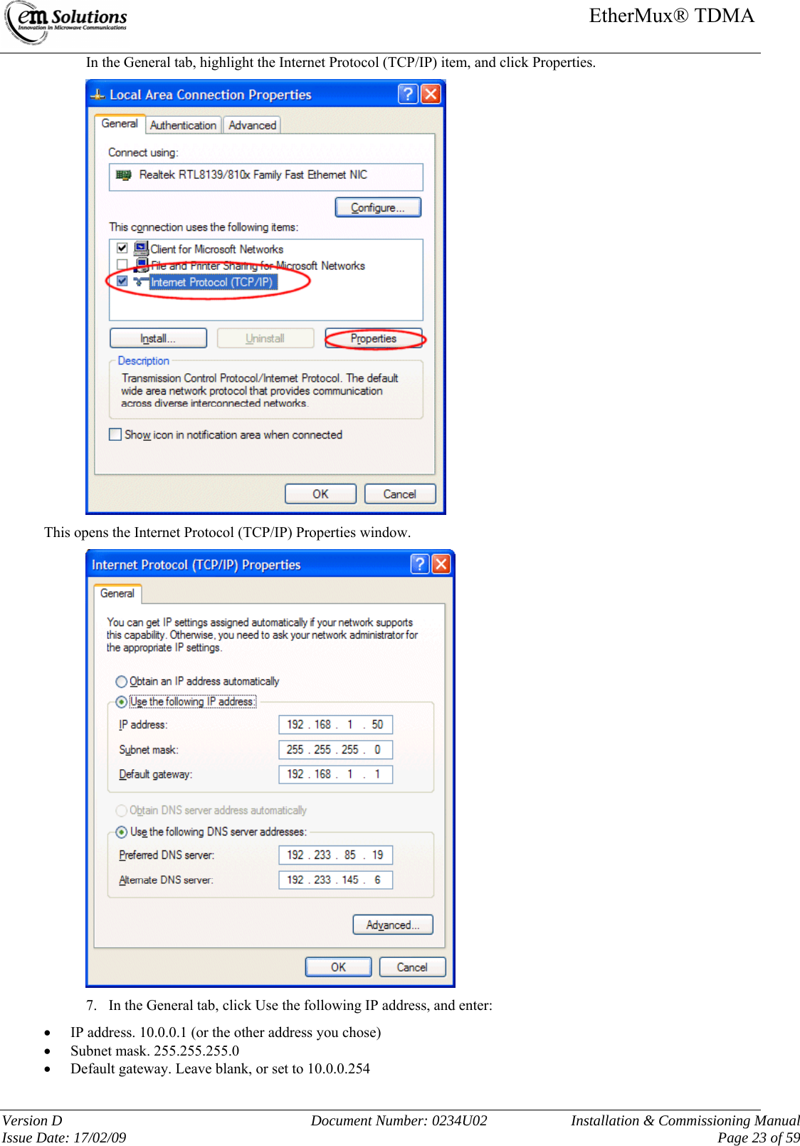
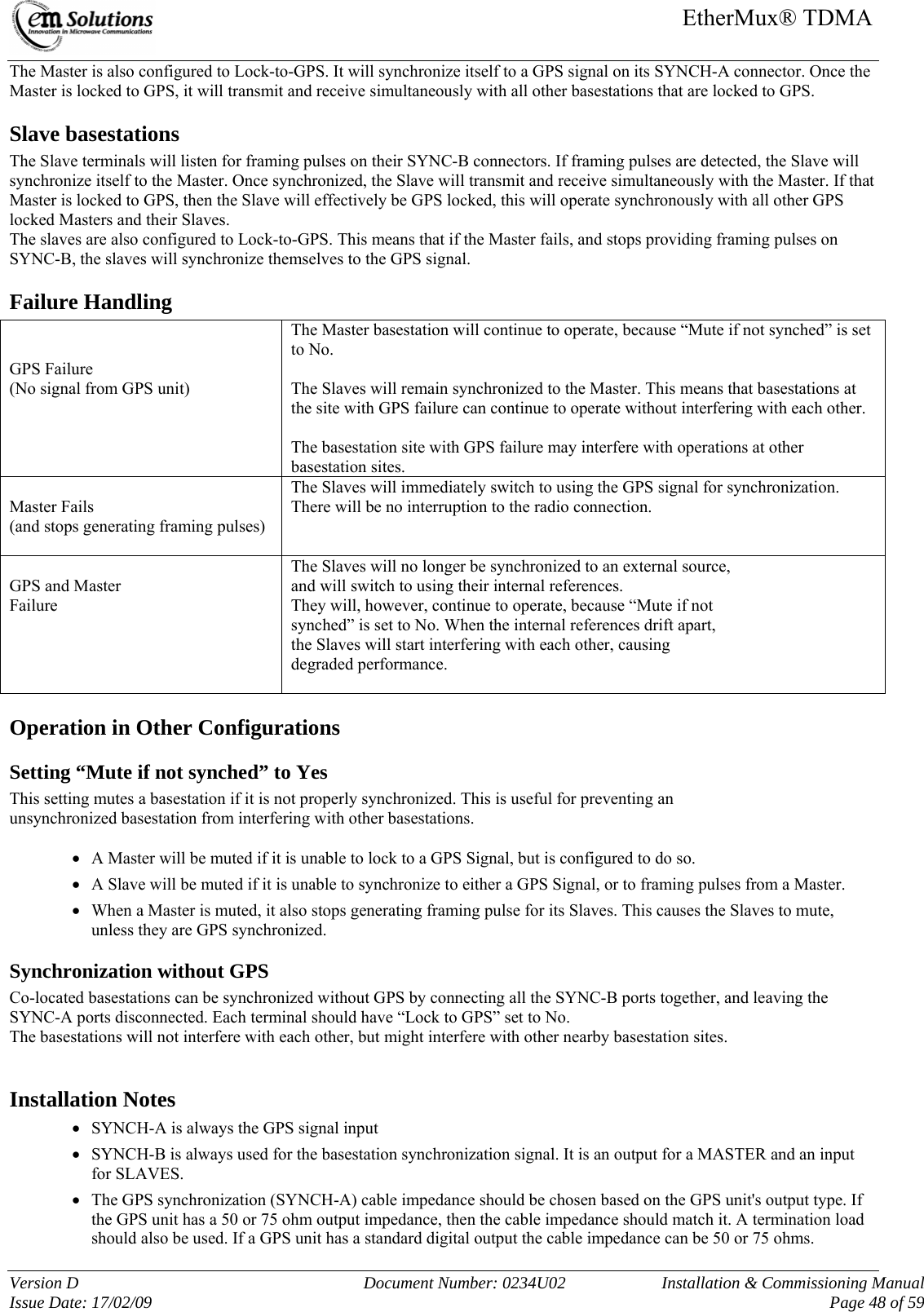
![EtherMux® TDMA Version D Document Number: 0234U02 Installation & Commissioning Manual Issue Date: 17/02/09 Page 20 of 59 Commissioning the EtherMux® TDMA Network What You Will Need to Commission the EtherMux® Network The following items are needed to perform Link commissioning: 1. Laptop with 100 Base-T port 2. Ethernet cross-over cable How to Commissioning the Radio Network Commissioning normally follows the following process: 1. Pre-configure terminals in workshop 2. Install Basestation and turn on power. 3. For each Subscriber • Install Subscriber and turn on power. • Adjust antenna alignment, if required. • Confirm connection to Basestation 4. Confirm network performs as expected. Before starting this process, ensure that you have a network plan, or summary, containing the following information: z Configuration settings for each terminal z Compass bearings for each antenna z Expected transmit and receive powers The commissioning steps are explained in the following sections. Pre-configuring terminals in workshop Refer to section “Basic Configuration of the EtherMux® TDMA Terminals” Base Station Installation 1. Install the Basestation terminal, antenna(s) and RF cabling. Figure 1 illustrates a typical installation. 2. Align antenna(s) using compass and spirit-level 3. Apply power to Basestation. 4. Confirm that the Basestation is operating by observing the Mode LED. After the boot sequence completes, the Mode LED should flash at a moderate rate. 5. [Optional step] Connect a laptop to the Basestation and confirm its configuration. Subscriber Installation 1. Install the Subscriber terminal, antenna(s) and RF cabling. Figure 1 illustrates a typical installation. 2. Align antenna using compass and spirit-level 3. Apply power to Subscriber. 4. Observe the Mode LED. After the boot sequence completes, the Mode LED should flash at a moderate rate, to indicate it is trying to connect to the Basestation. 5. The Mode LED should flash slowly once the Subscriber has successfully connected to the Basestation. If this doesn't happen, please consult the Trouble Shooting section “Subscriber doesn't connect.” 6. View the Subscriber's “Status” web page. Check that • Link Status reports “Connected to Basestation” • RX Power estimate agrees with expected receive power. 7. Align antenna(s) if RX power is too low. 8. Confirm connection to Basestation by browsing the webpage of the Basestation. Do this by typing the Basestation's IP address into your browser's address window.](https://usermanual.wiki/EM-Solutions/274H/User-Guide-1069306-Page-21.png)
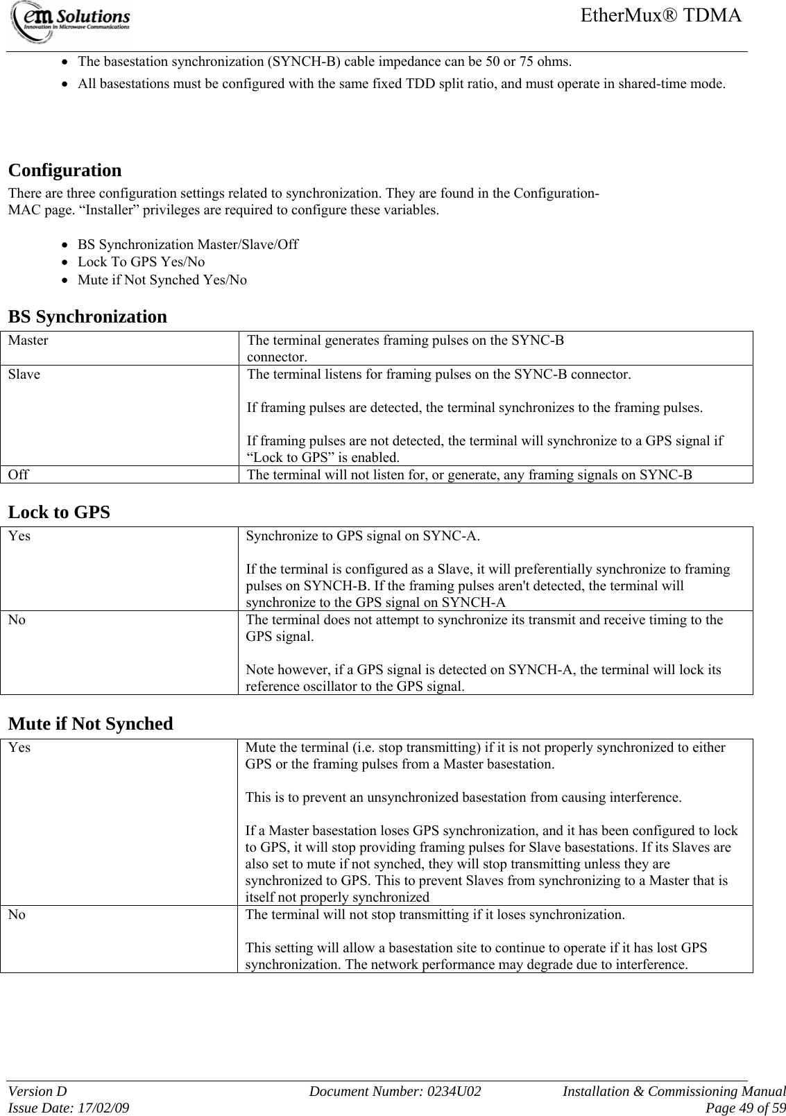
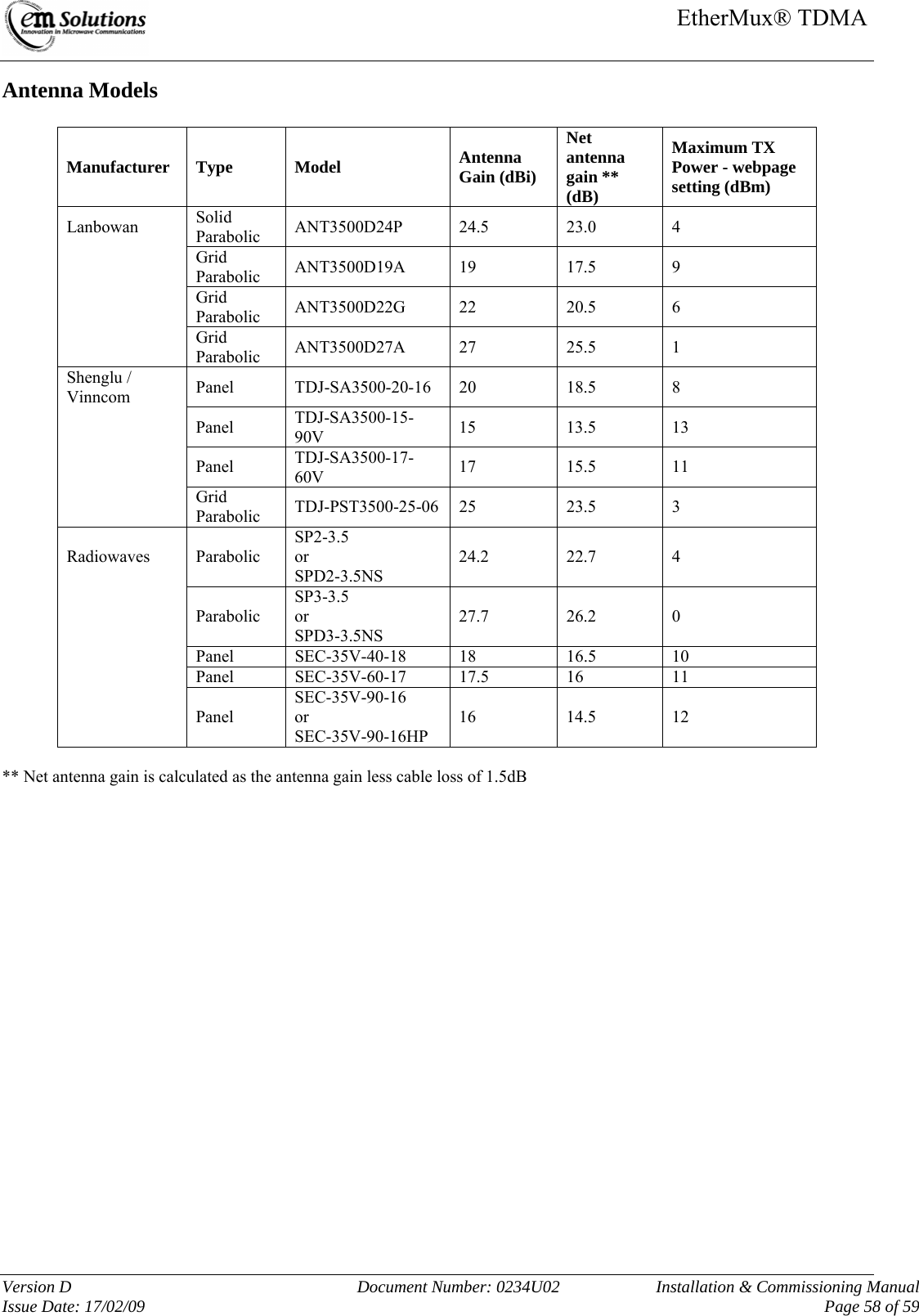
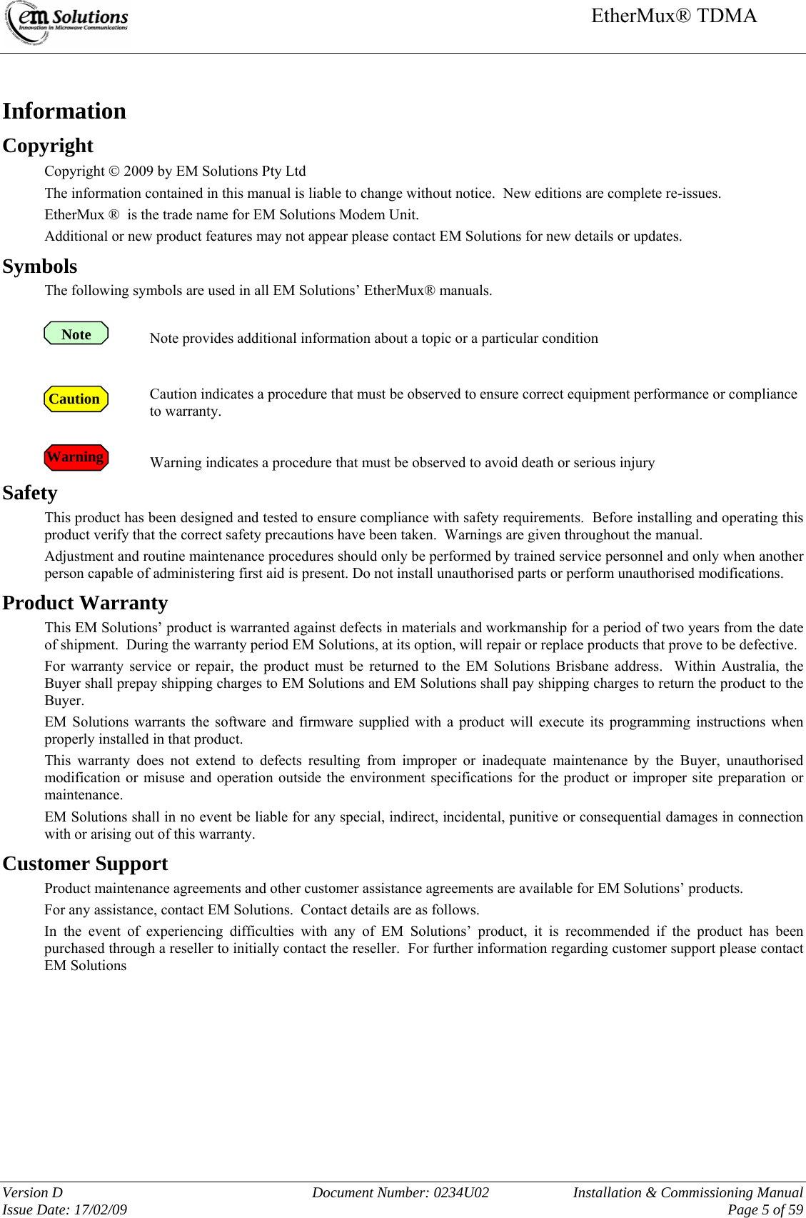
![EtherMux® TDMA Version D Document Number: 0234U02 Installation & Commissioning Manual Issue Date: 17/02/09 Page 57 of 59 FCC Transmitter Power Settings for EMS nominated Antennas: The RF output power and selection must be professionally programmed and installed by the manufacturer or trained professional installer. These settings may have to be altered to take into account any cable losses. Transmitted Power Levels and peak EIRP power density should not exceed the requirements of FCC Section 90.1321(a) (90.205). As per 90.1321(a) – The maximum EIRP is limited to 25 Watts/25 MHz (44 dBm/25 MHz), and the peak EIRP power density is limited to 1W/MHz (30dBm/MHz). Calculation for EIRP (Equivalent Isotropically Radiated Power) – RMS value EIRP (RMS) = P + A – C Where P is output power setting (RMS value) A is EUT antenna gain C is EUT cable loss Determining the Maximum TX power setting for Local Power Control The maximum TX power (rms) value that can be set at the web interface is limited by the peak EIRP power density specification for a given antenna gain and cable loss. The following formula can be used to determine the webpage setting for Local power control, as shown below. This equation is based on measured results of the peak EIRP power density, with margin included to ensure compliance with the specification. Maximum TX Power Target = integer value of [ 27dBm – Antenna gain (dB) + Cable loss (dB) ] This is shown for a number of recommended antennas in the following table. Note Caution](https://usermanual.wiki/EM-Solutions/274H/User-Guide-1069306-Page-58.png)