EMS Technologies Canada HSD-MK2 Satcom Transeiver User Manual MN 1252 33412
EMS Technologies Canada, Ltd. Satcom Transeiver MN 1252 33412
UserManual.wiki
>
EMS Technologies Canada
>
HSD MK2 User Manual
HSD-MK2 User Manual
Navigation menu
Upload a User Manual
Namespaces
Wiki Guide
HTML
PDF
Info
Views
User Manual
Discussion / Help
Navigation
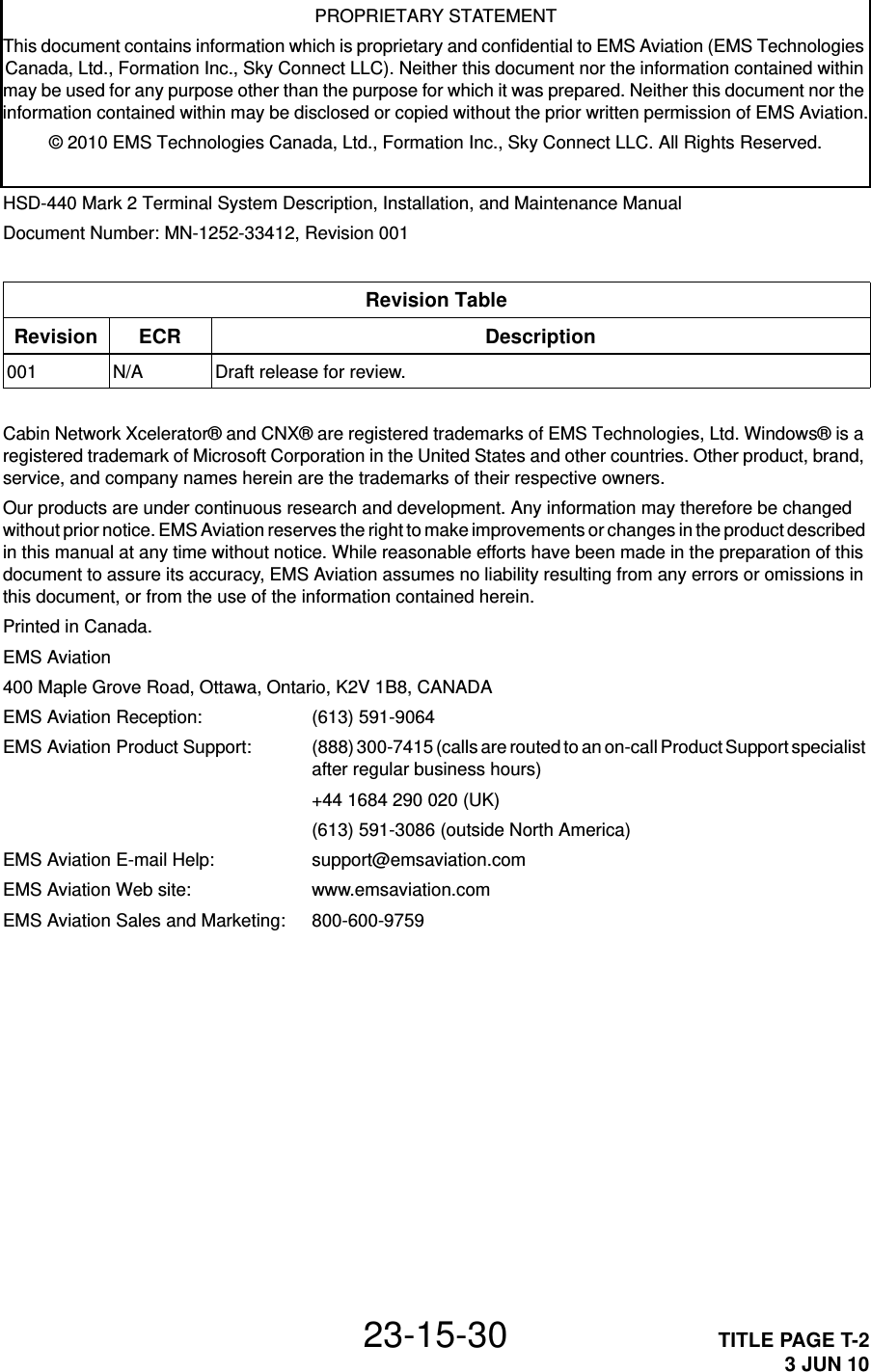

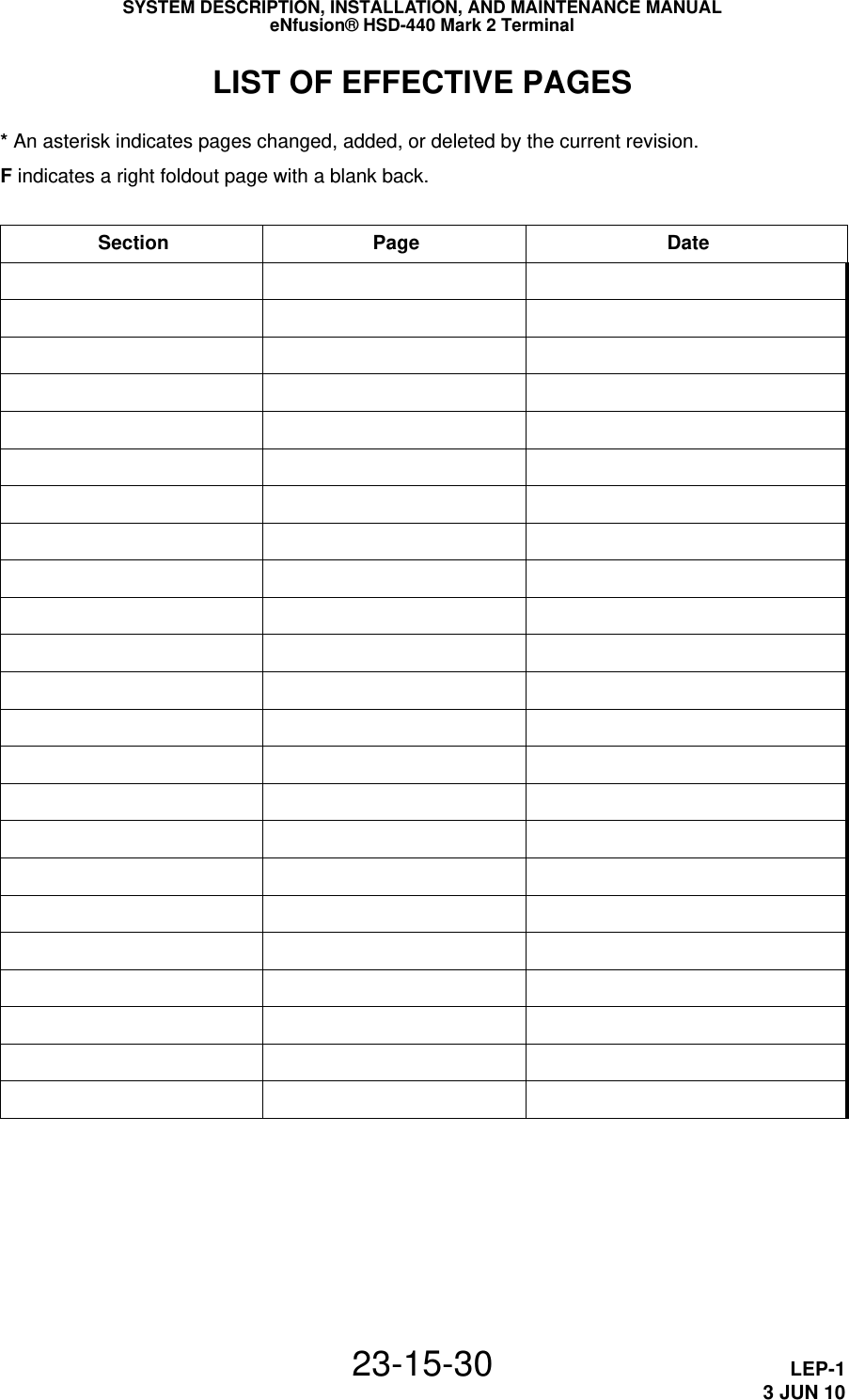

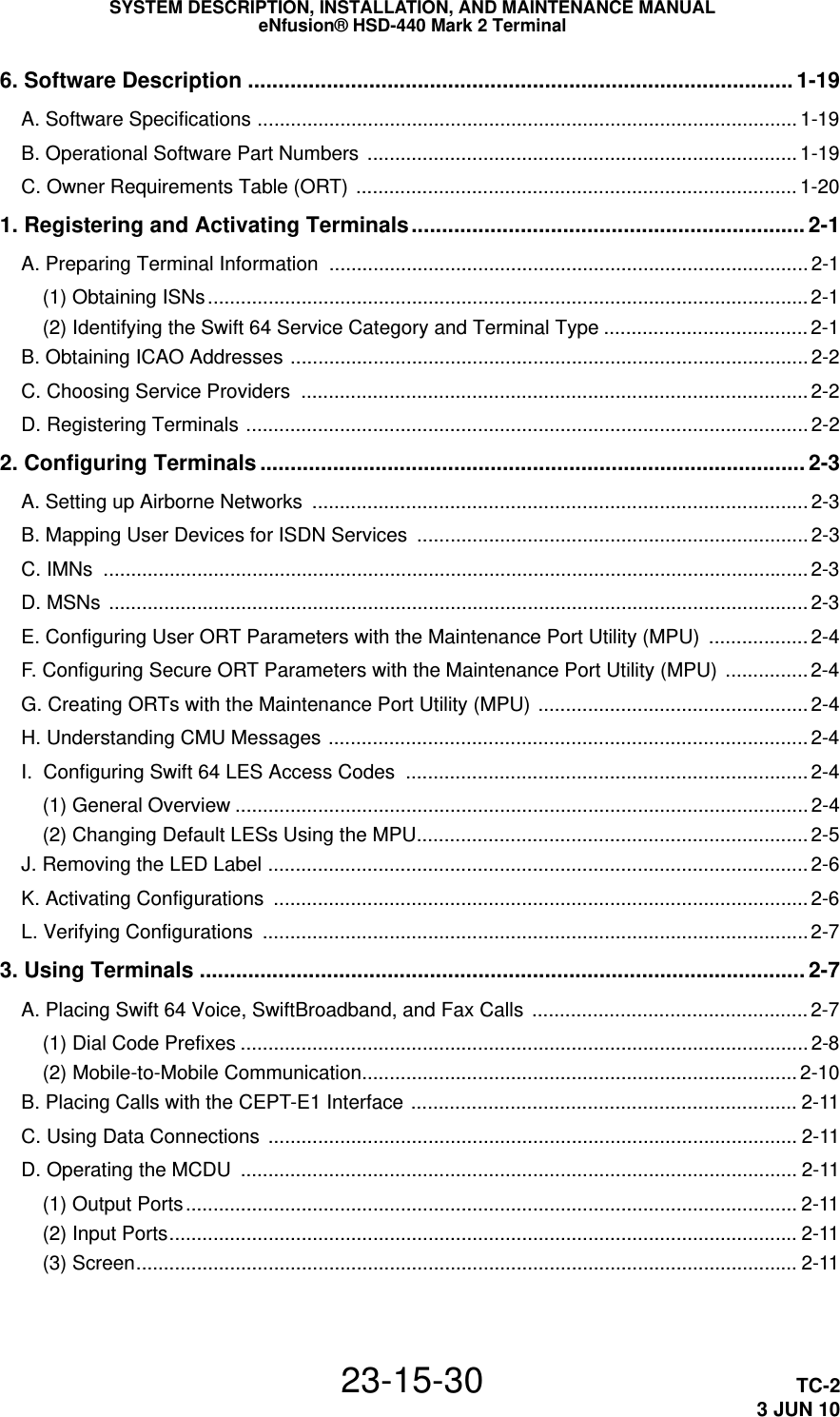


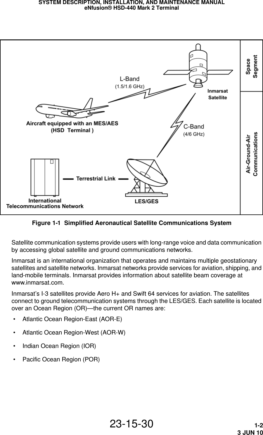
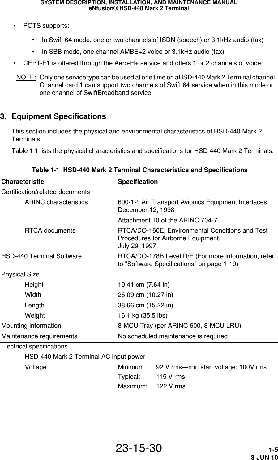


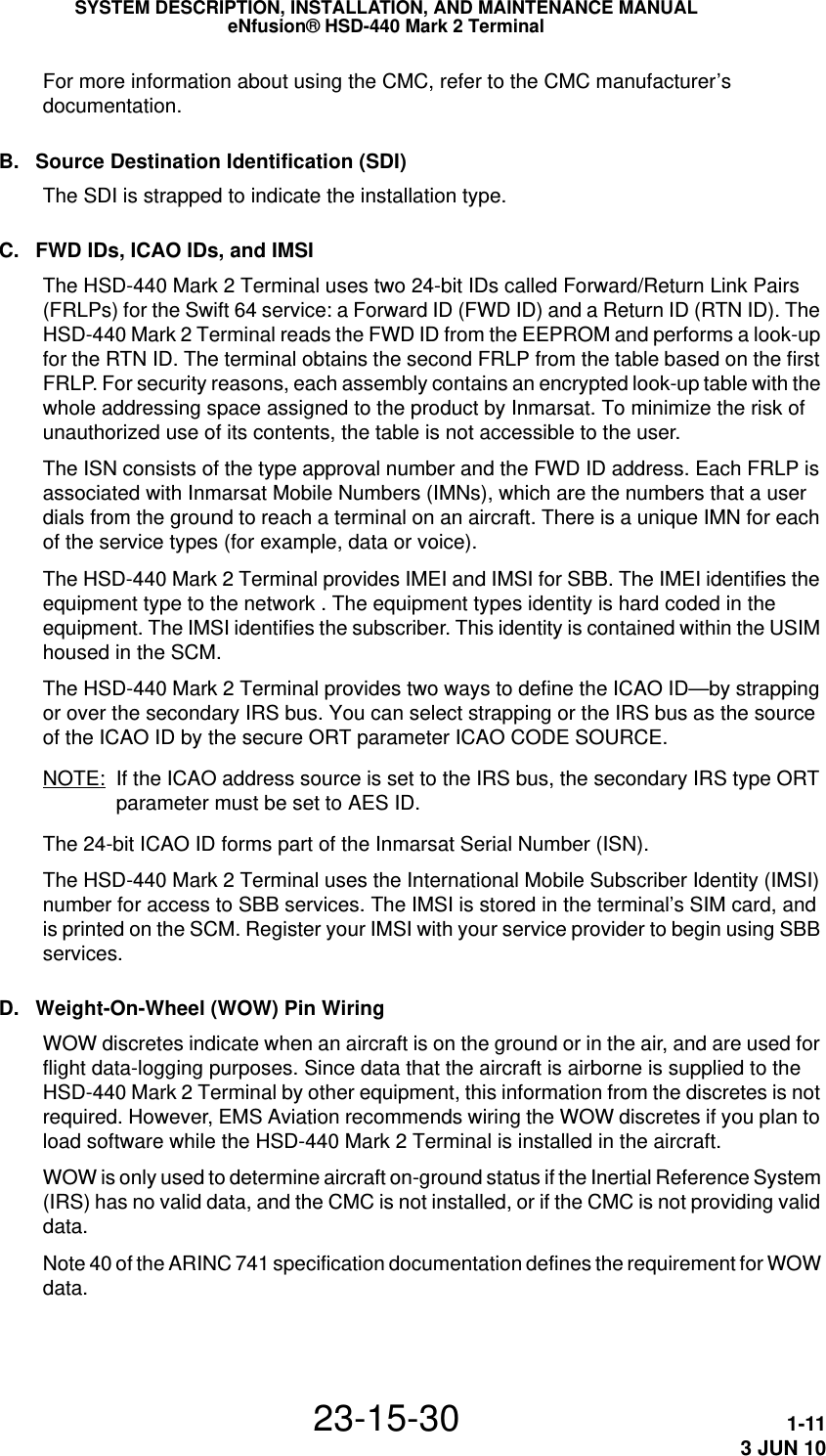
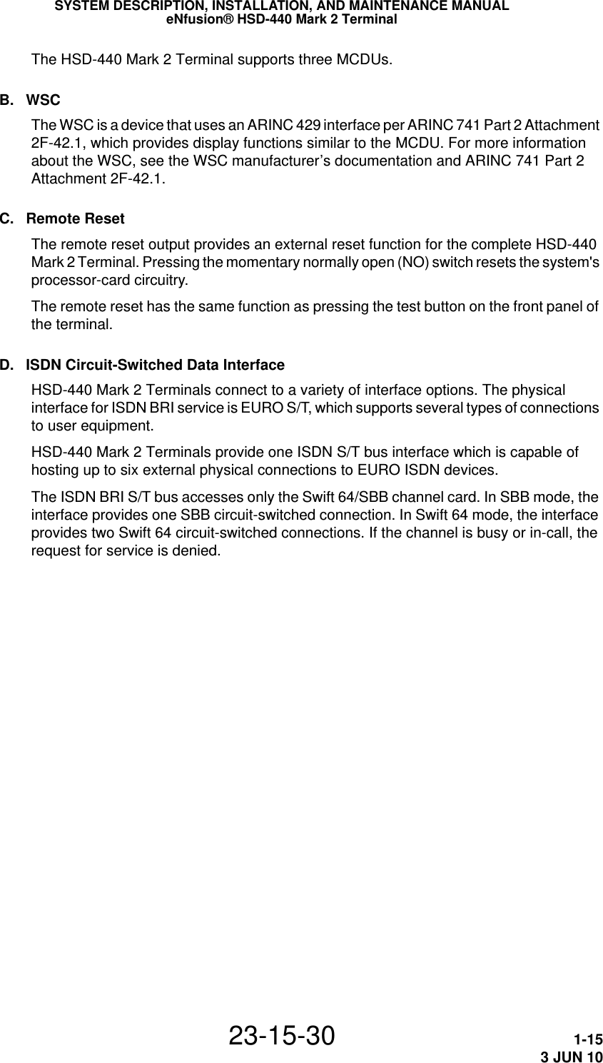
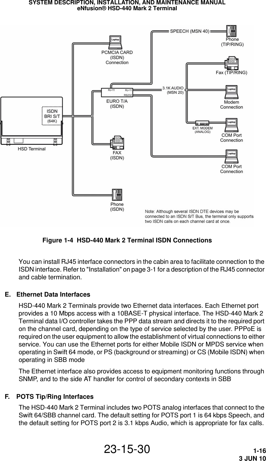
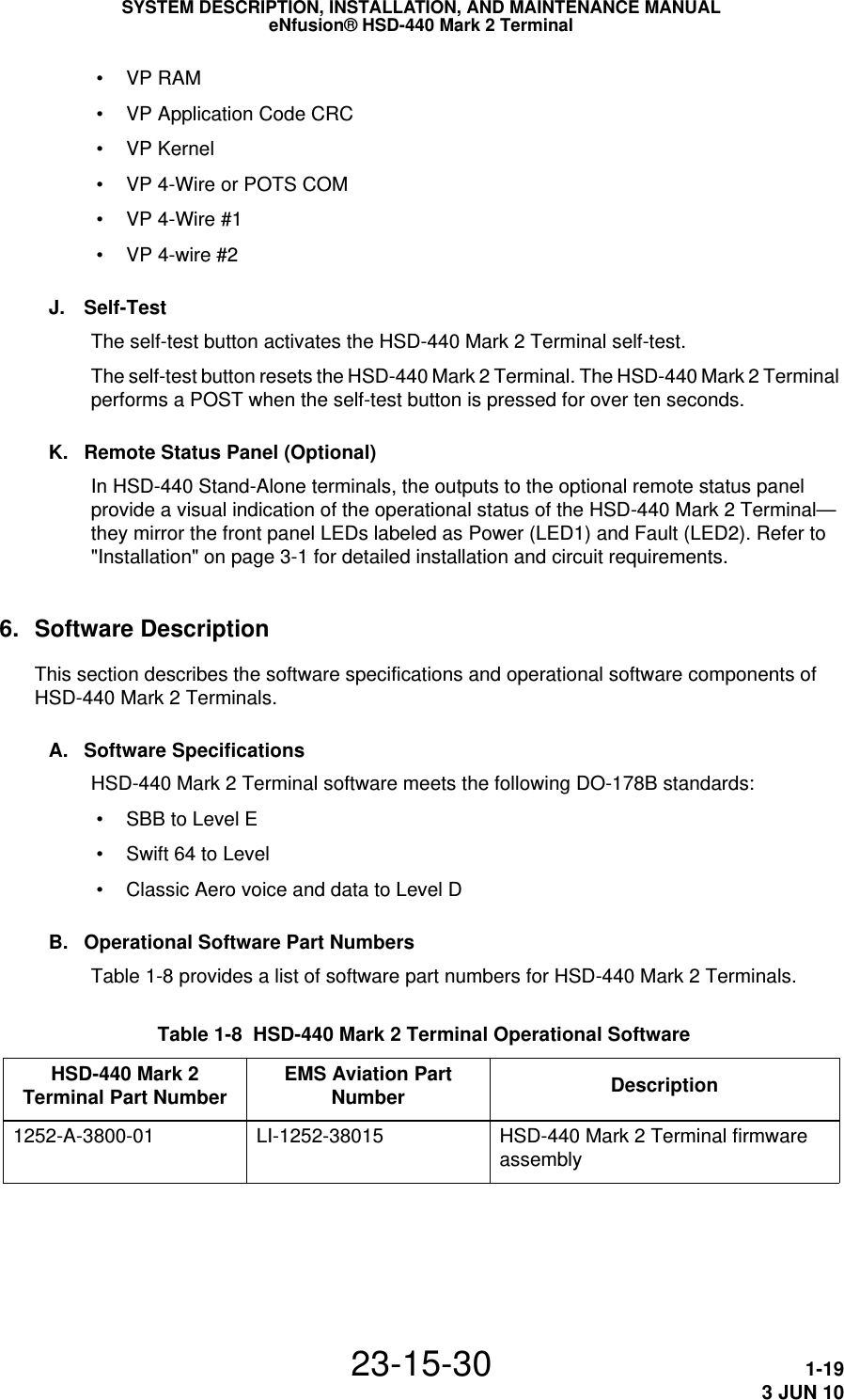
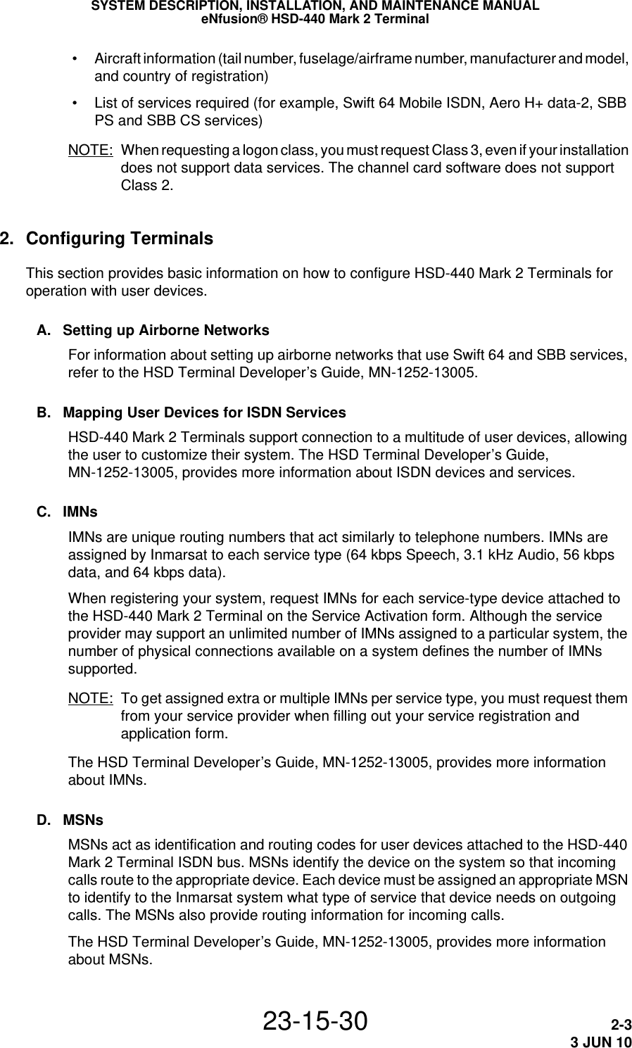
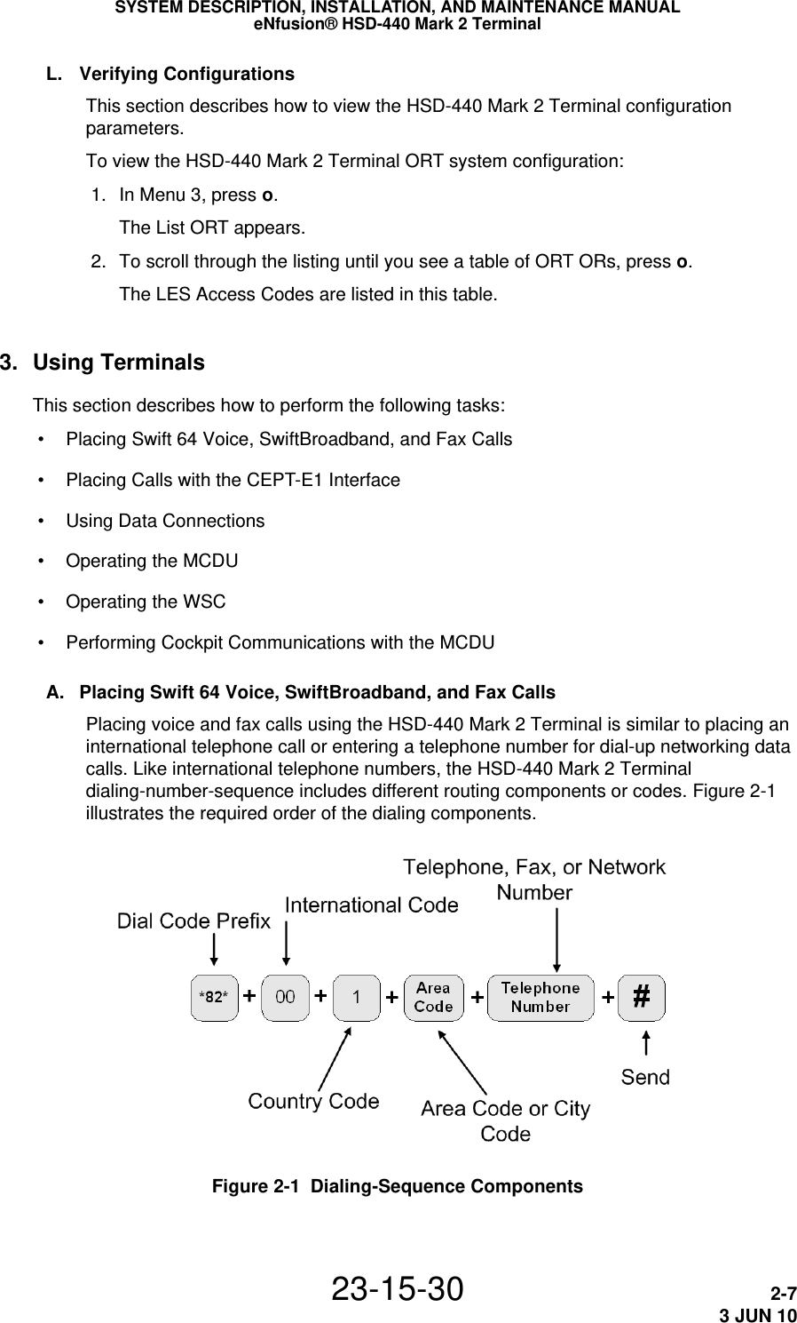
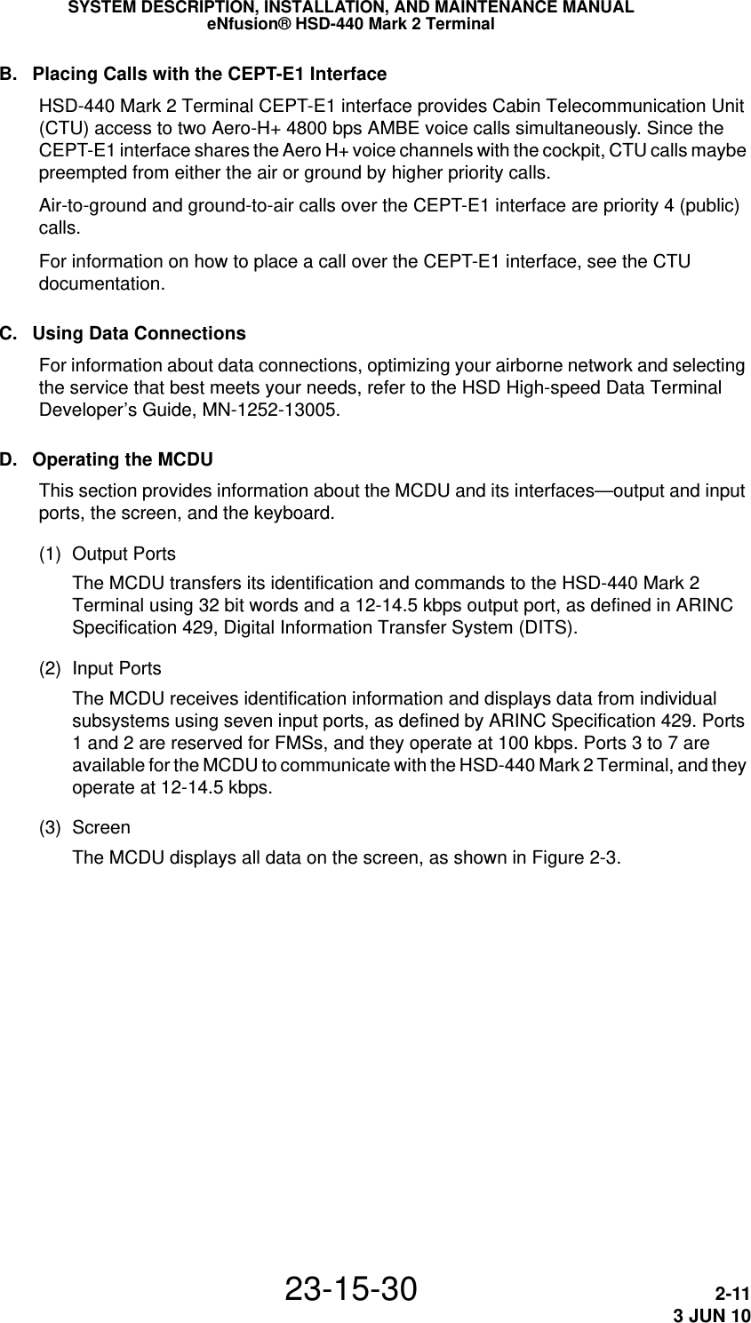
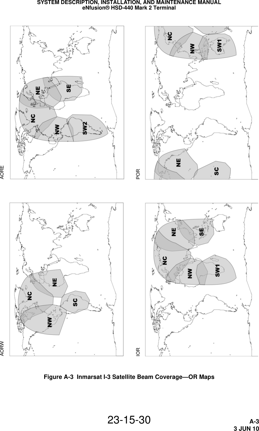
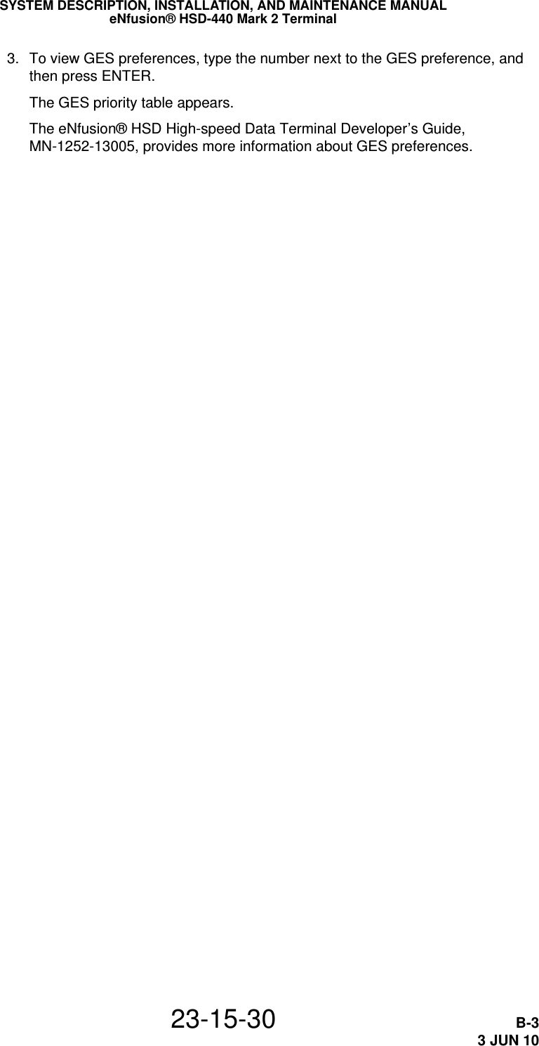
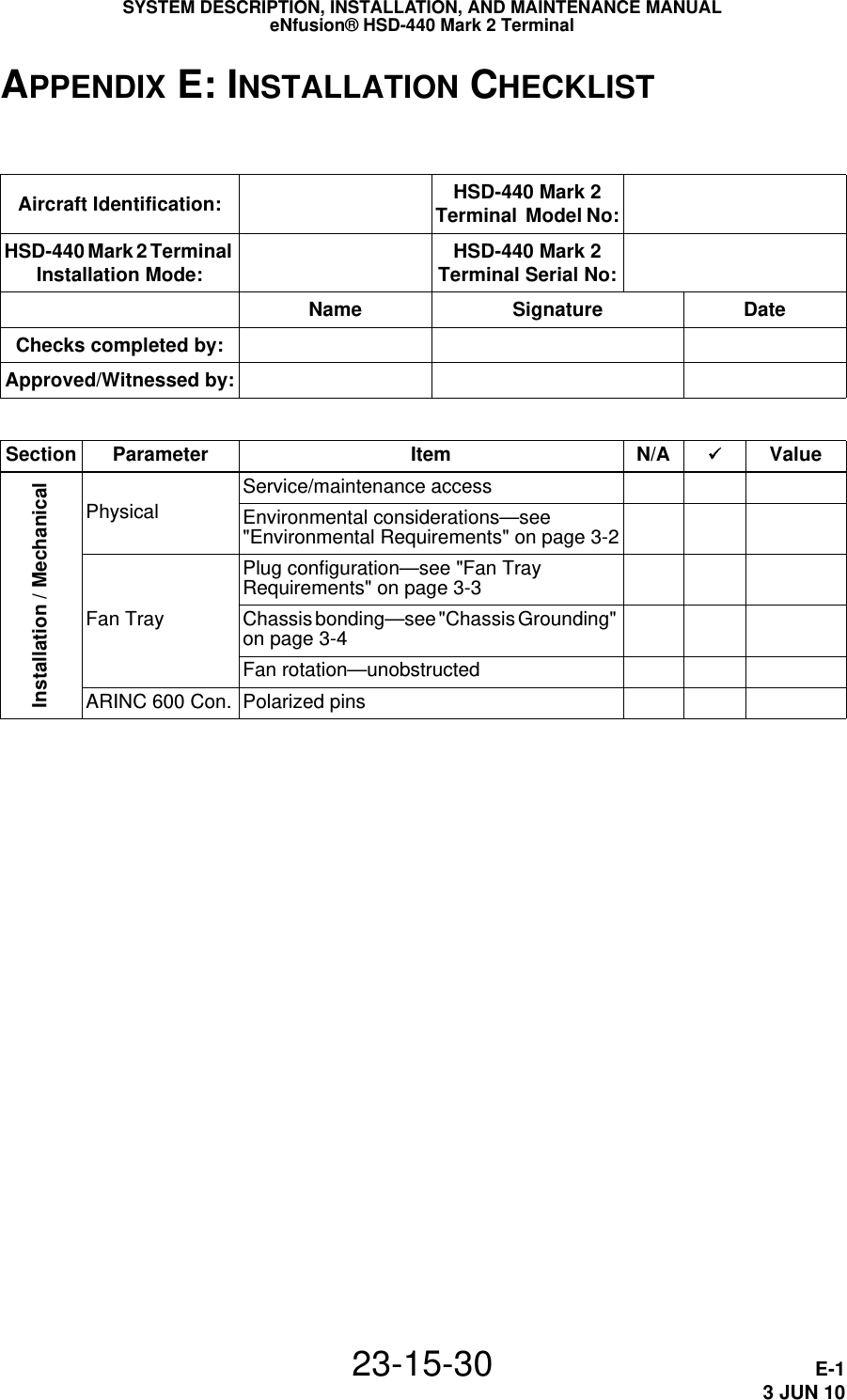
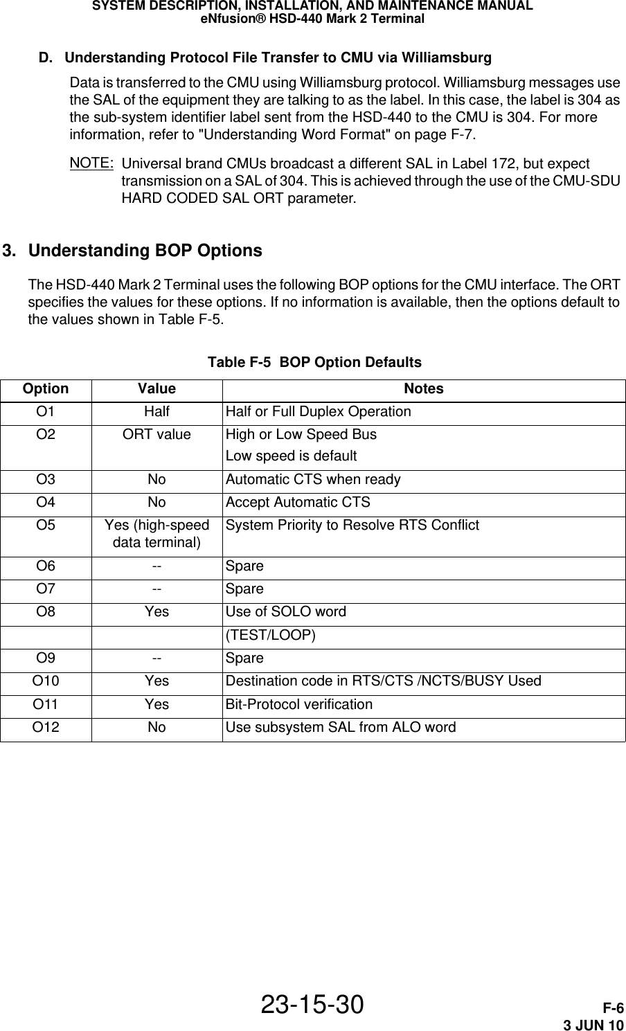
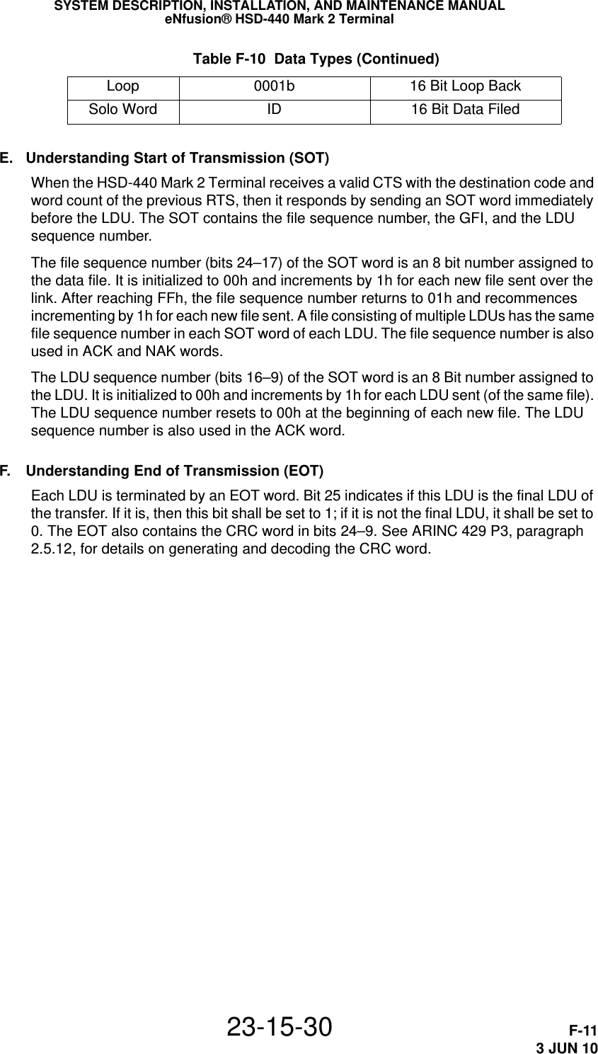
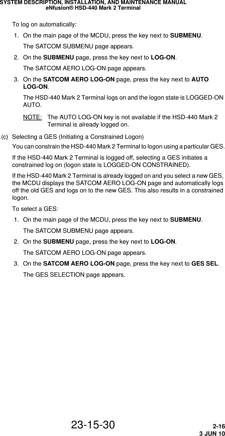
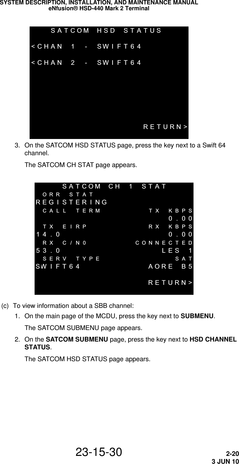
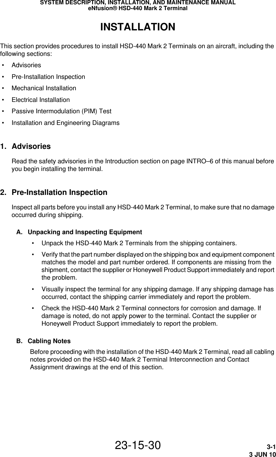
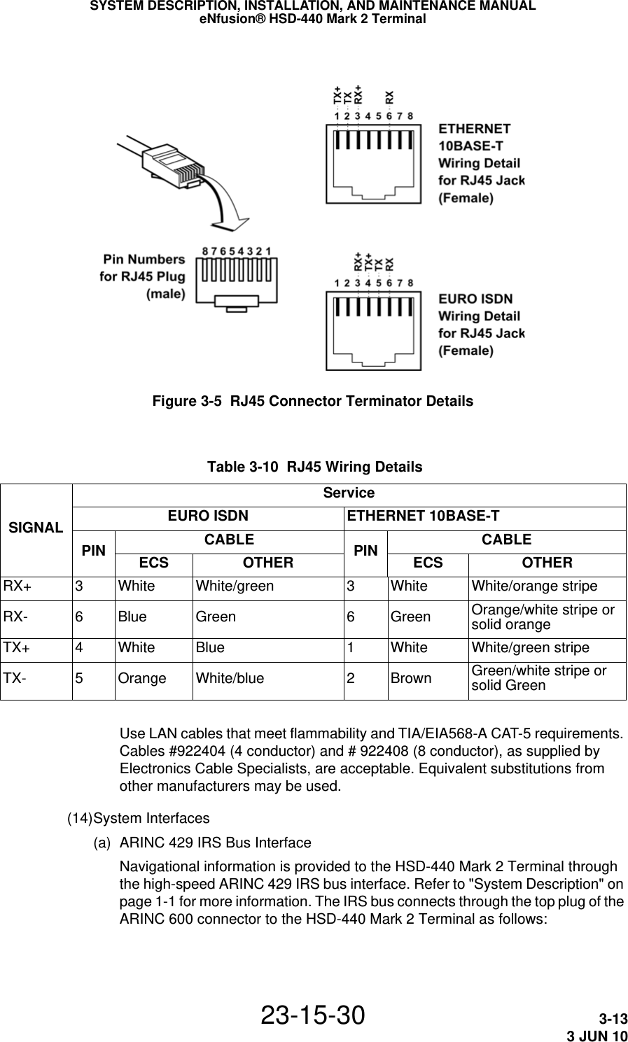
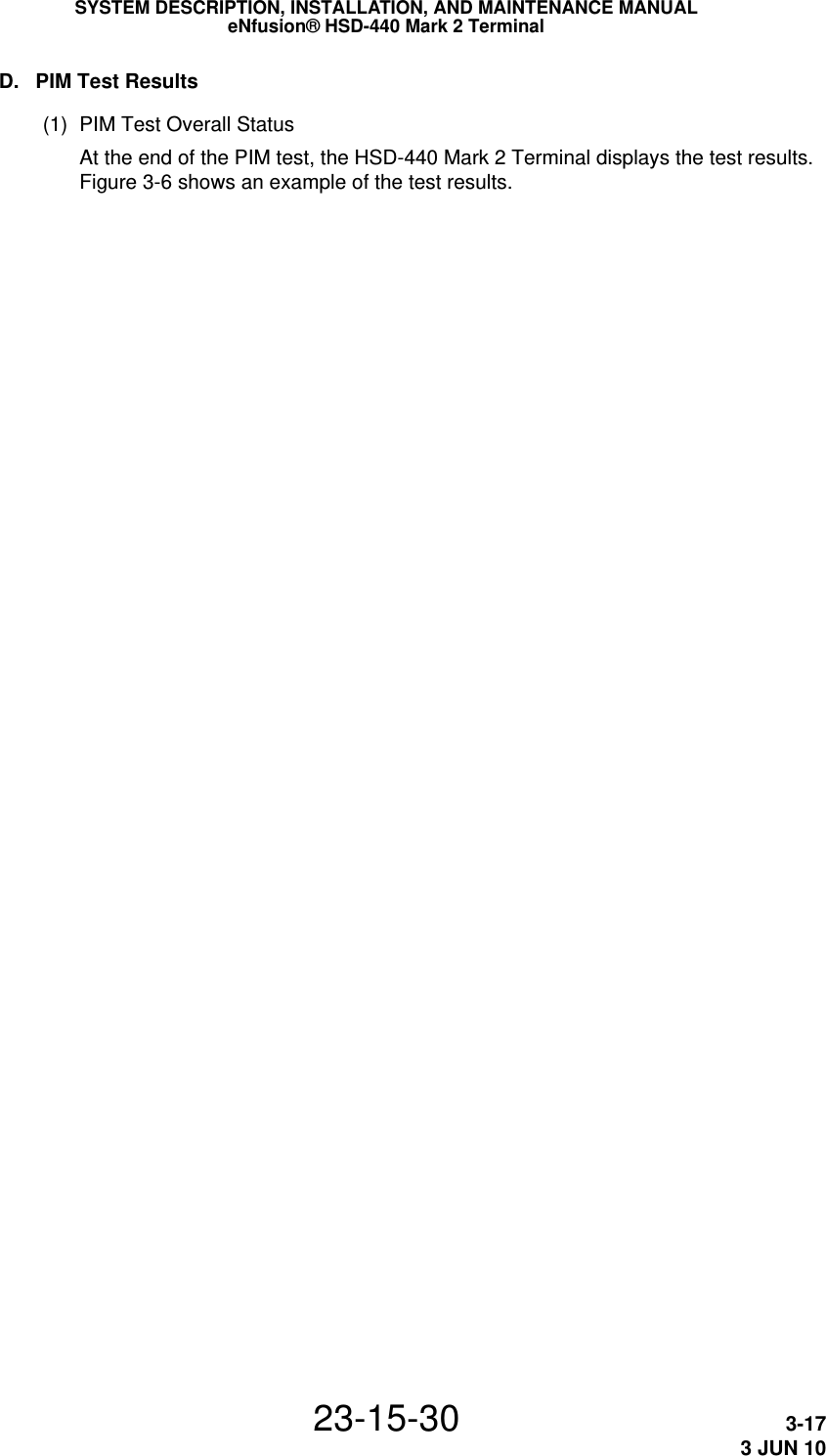
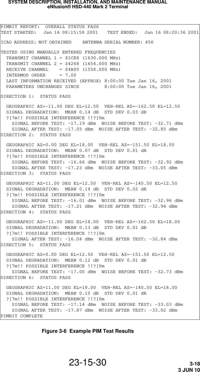
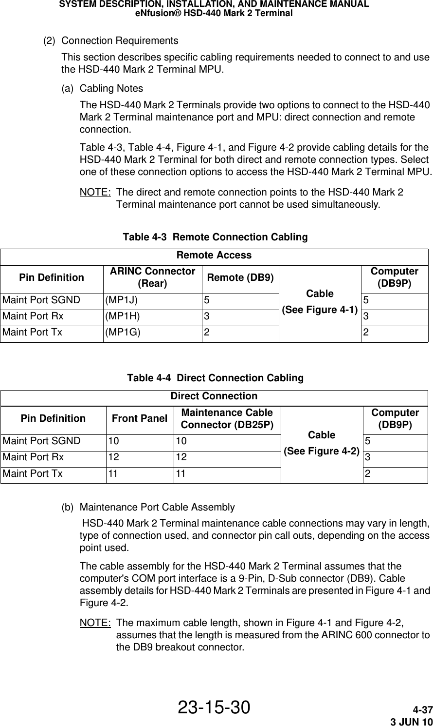
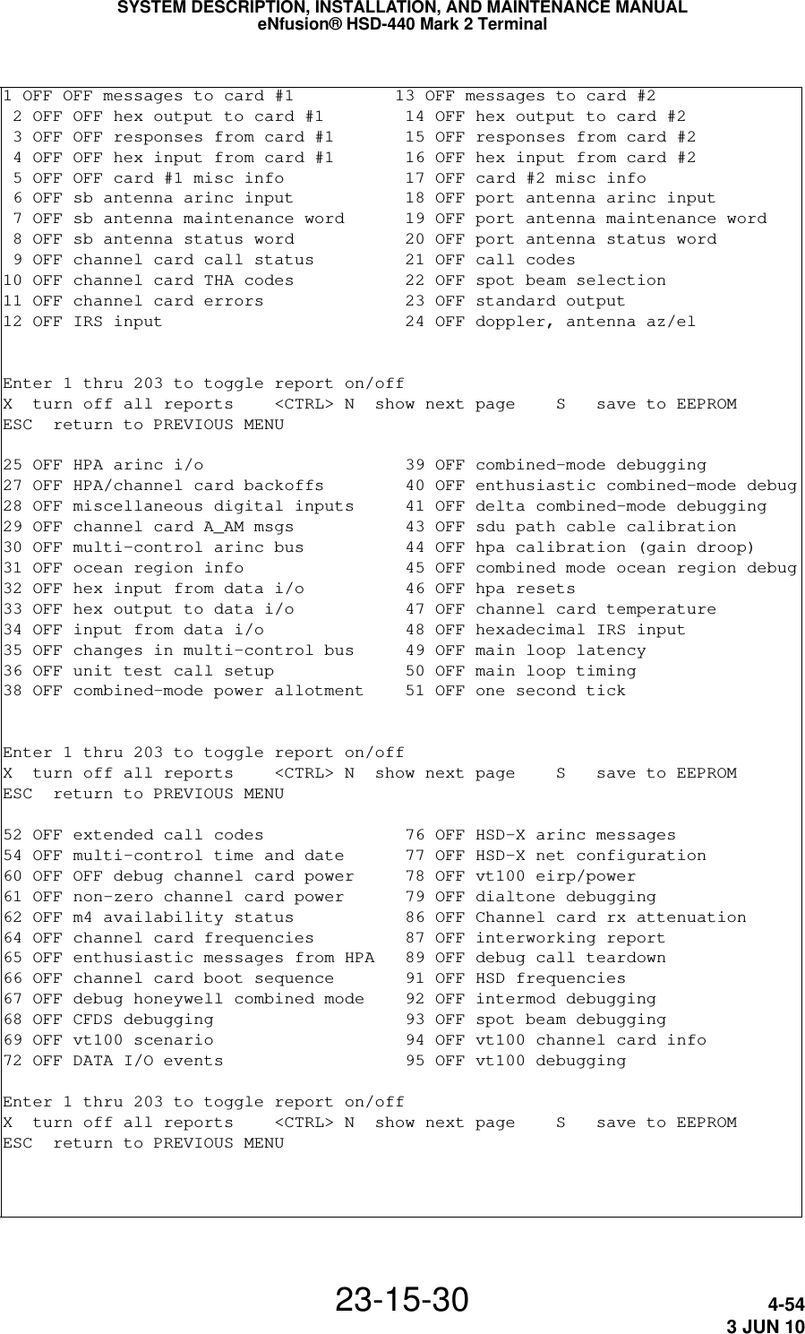
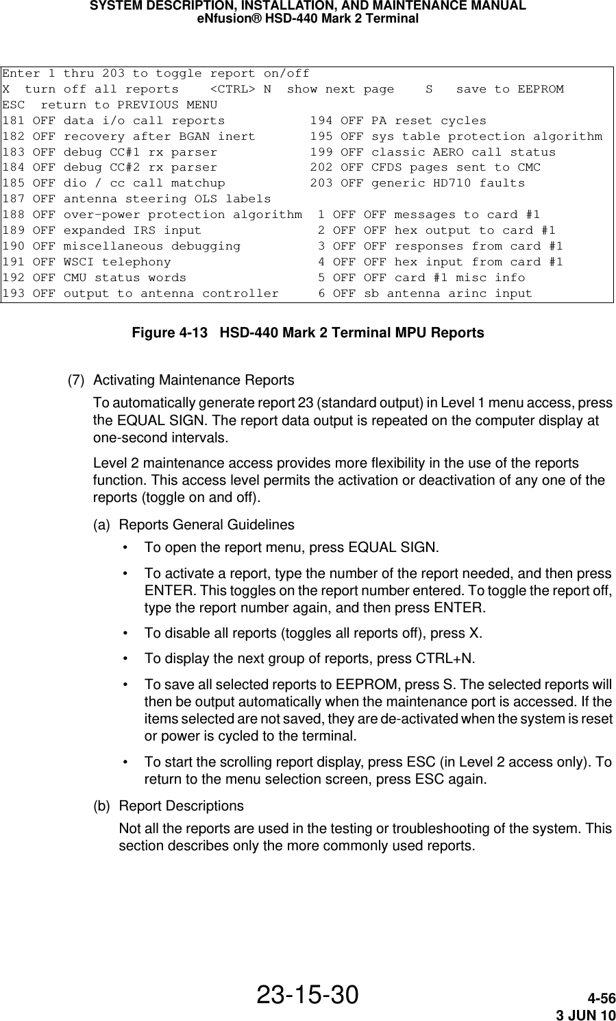
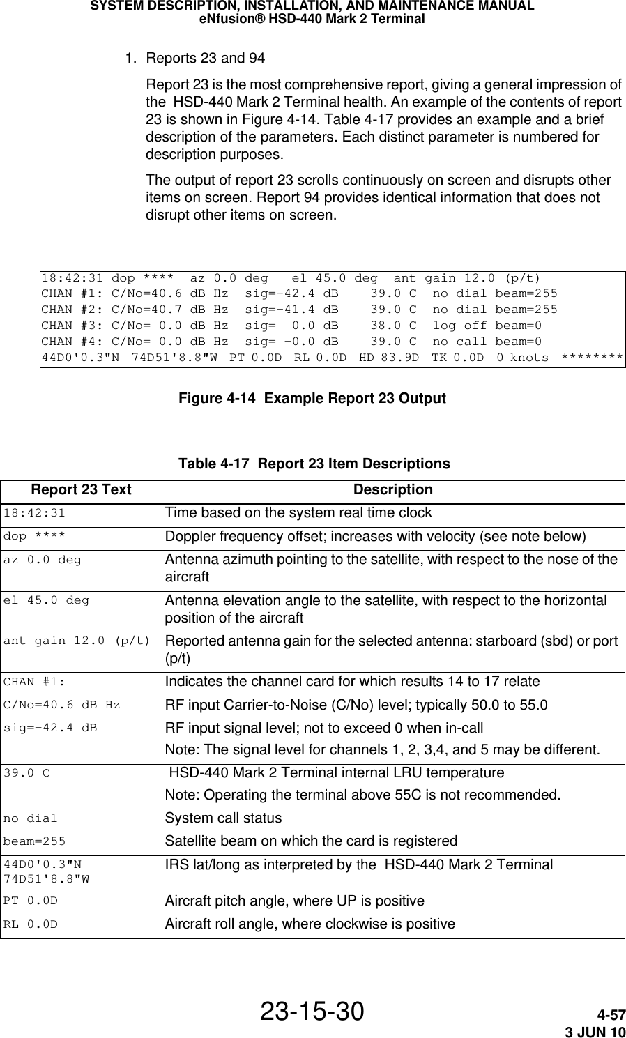
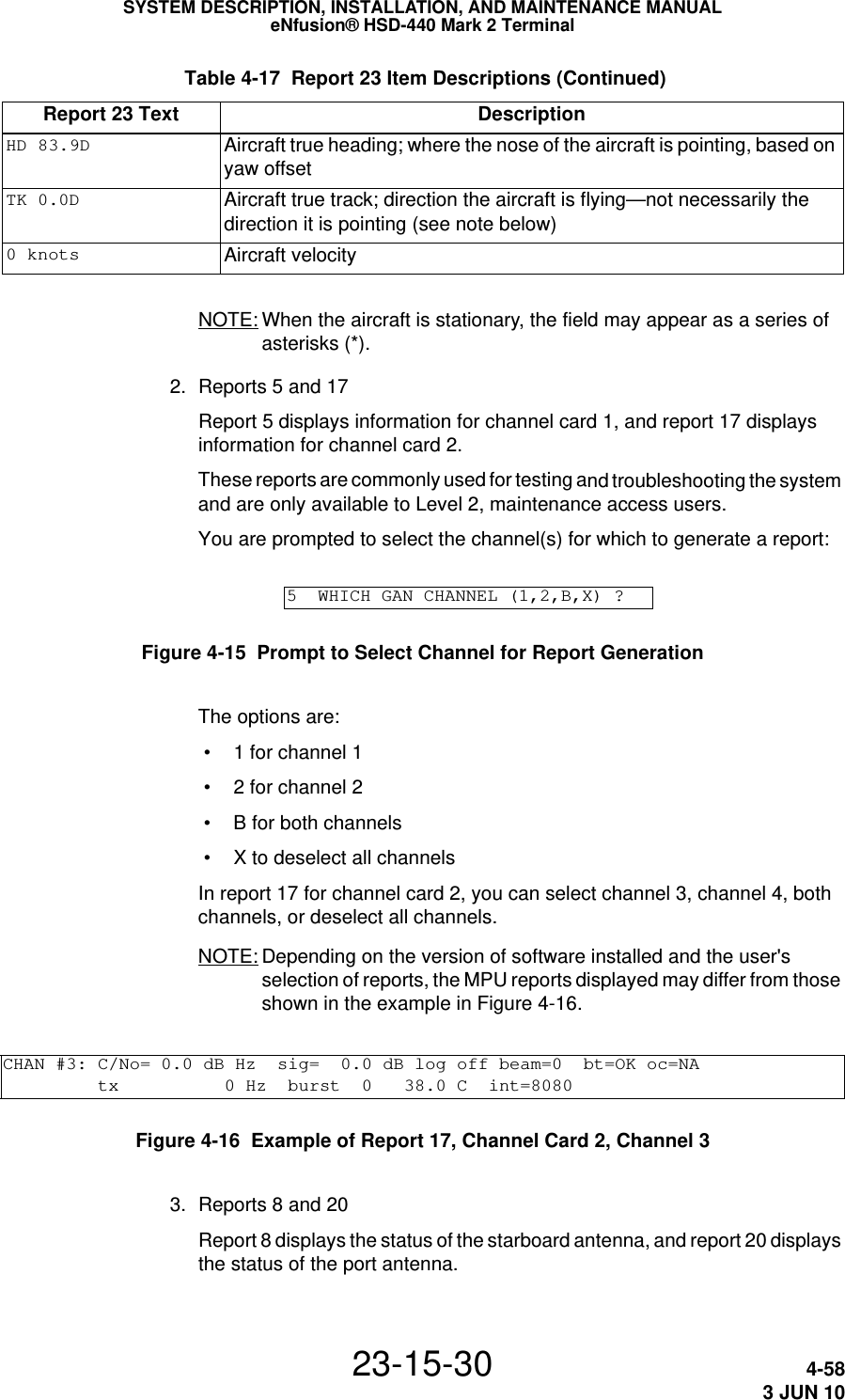
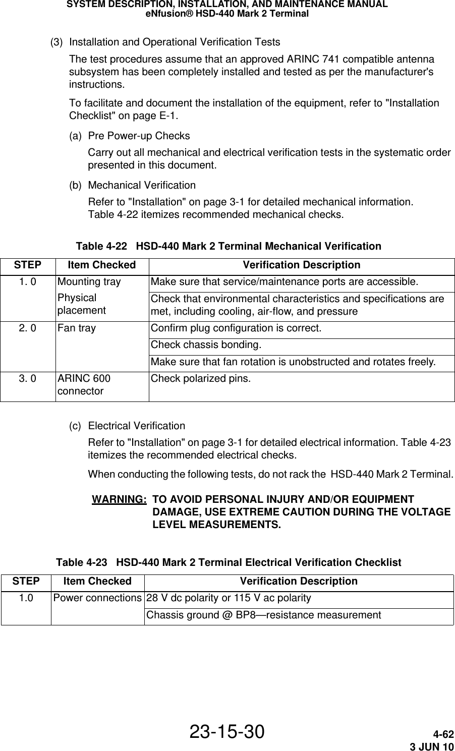
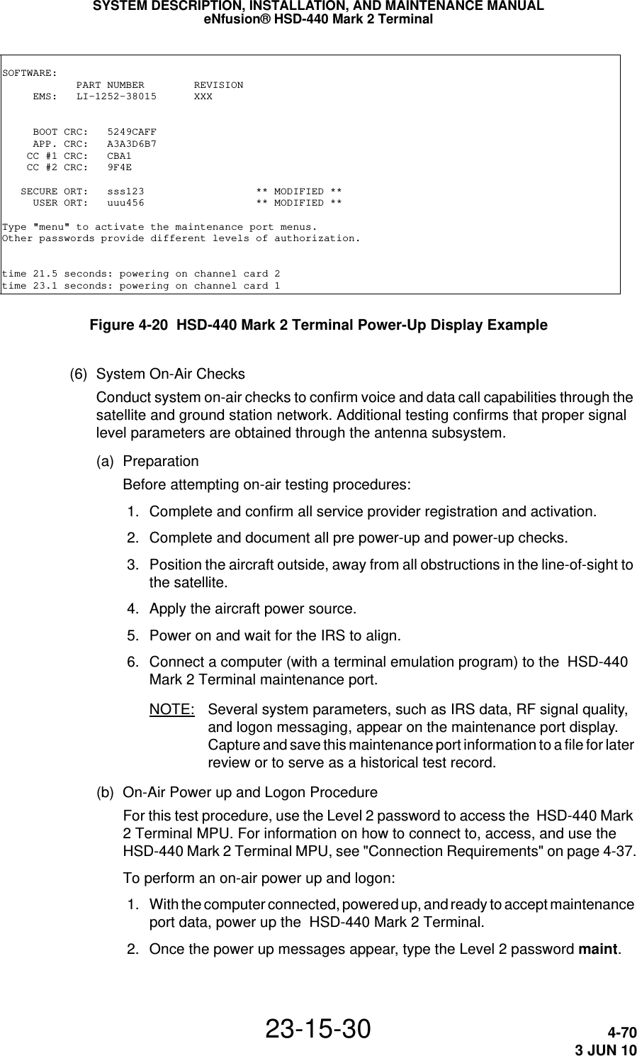
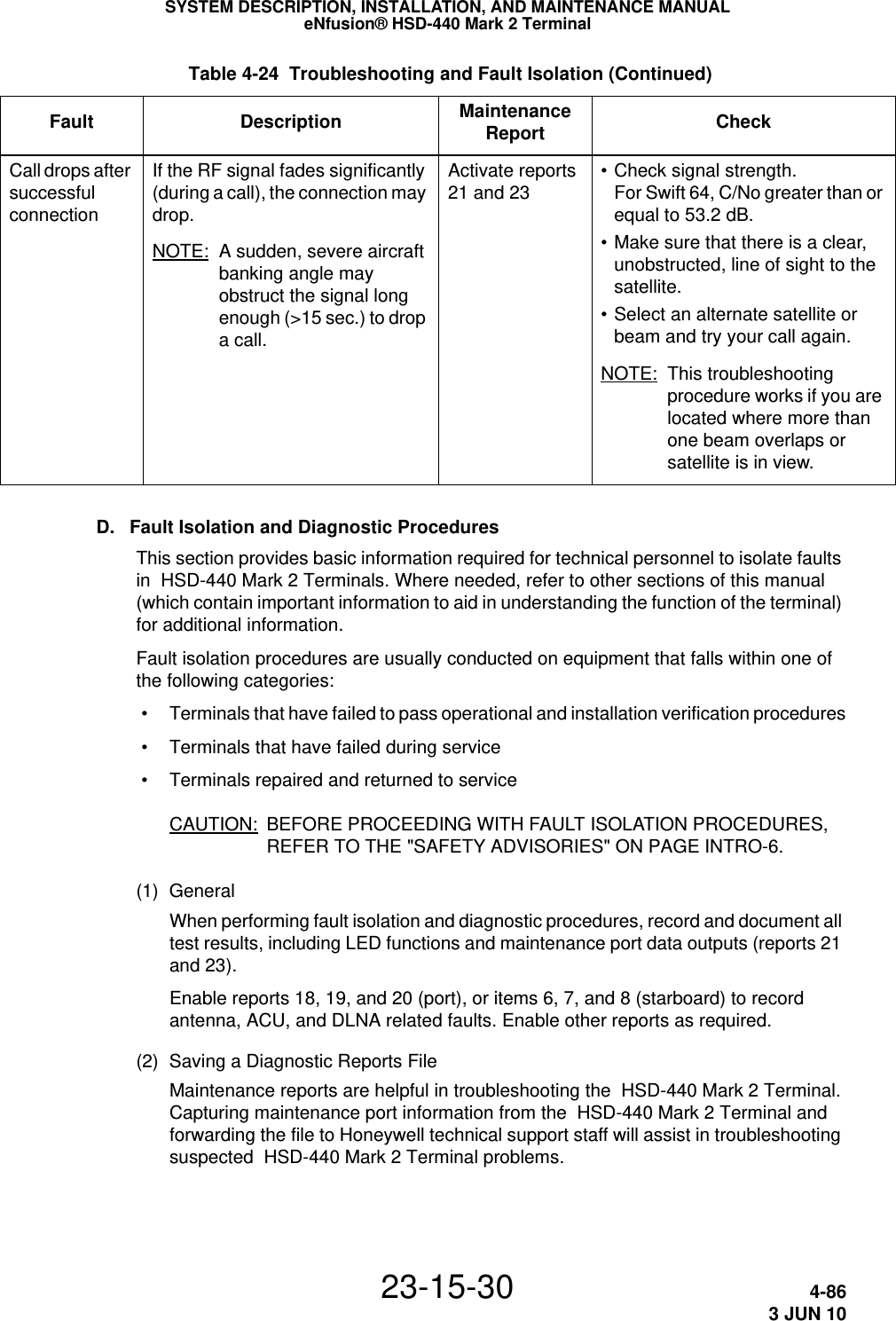
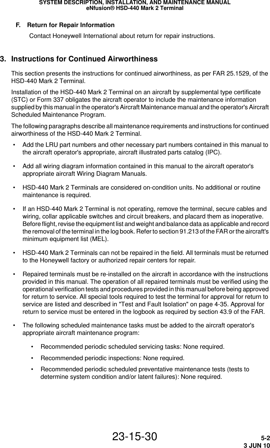
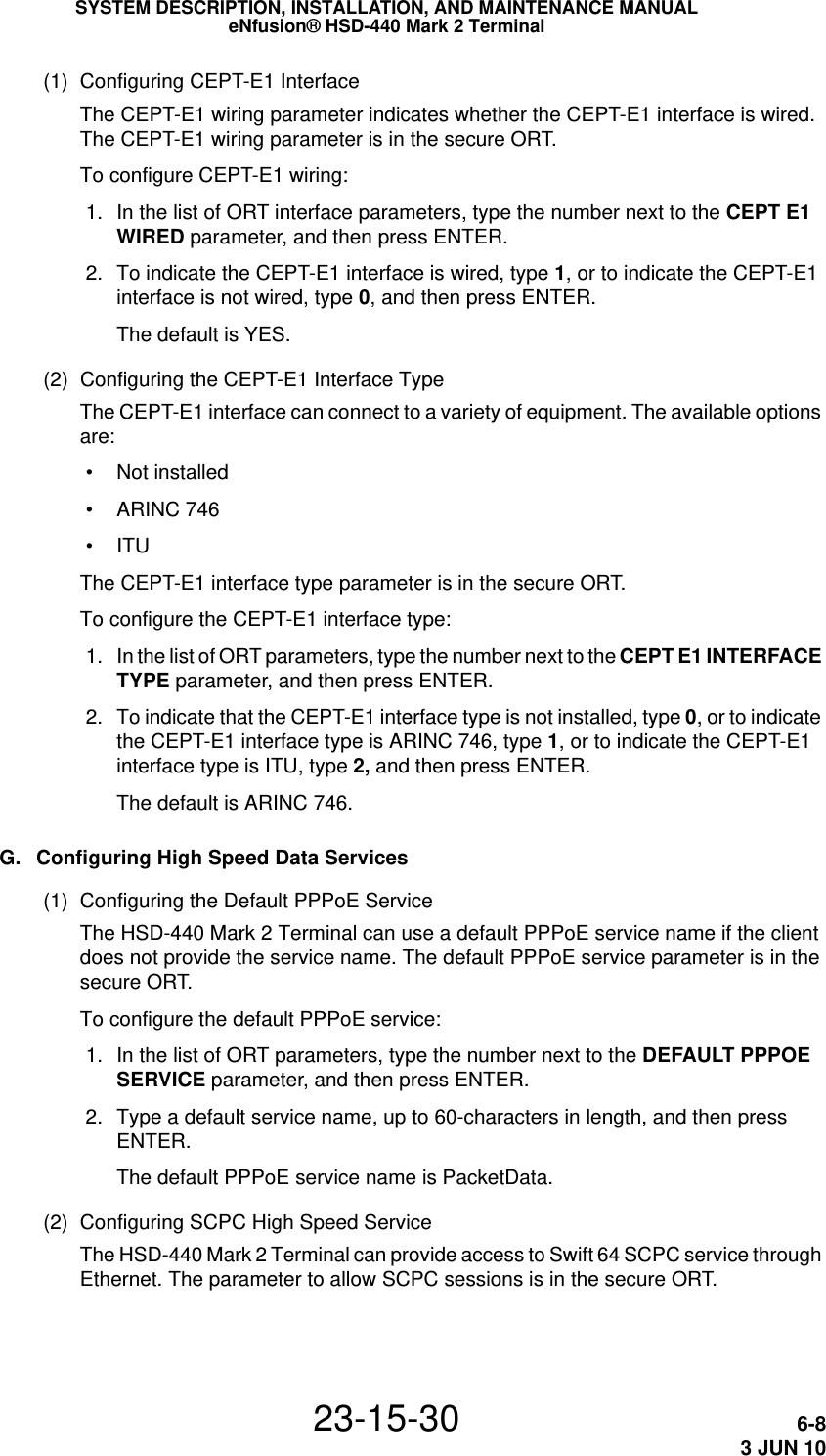
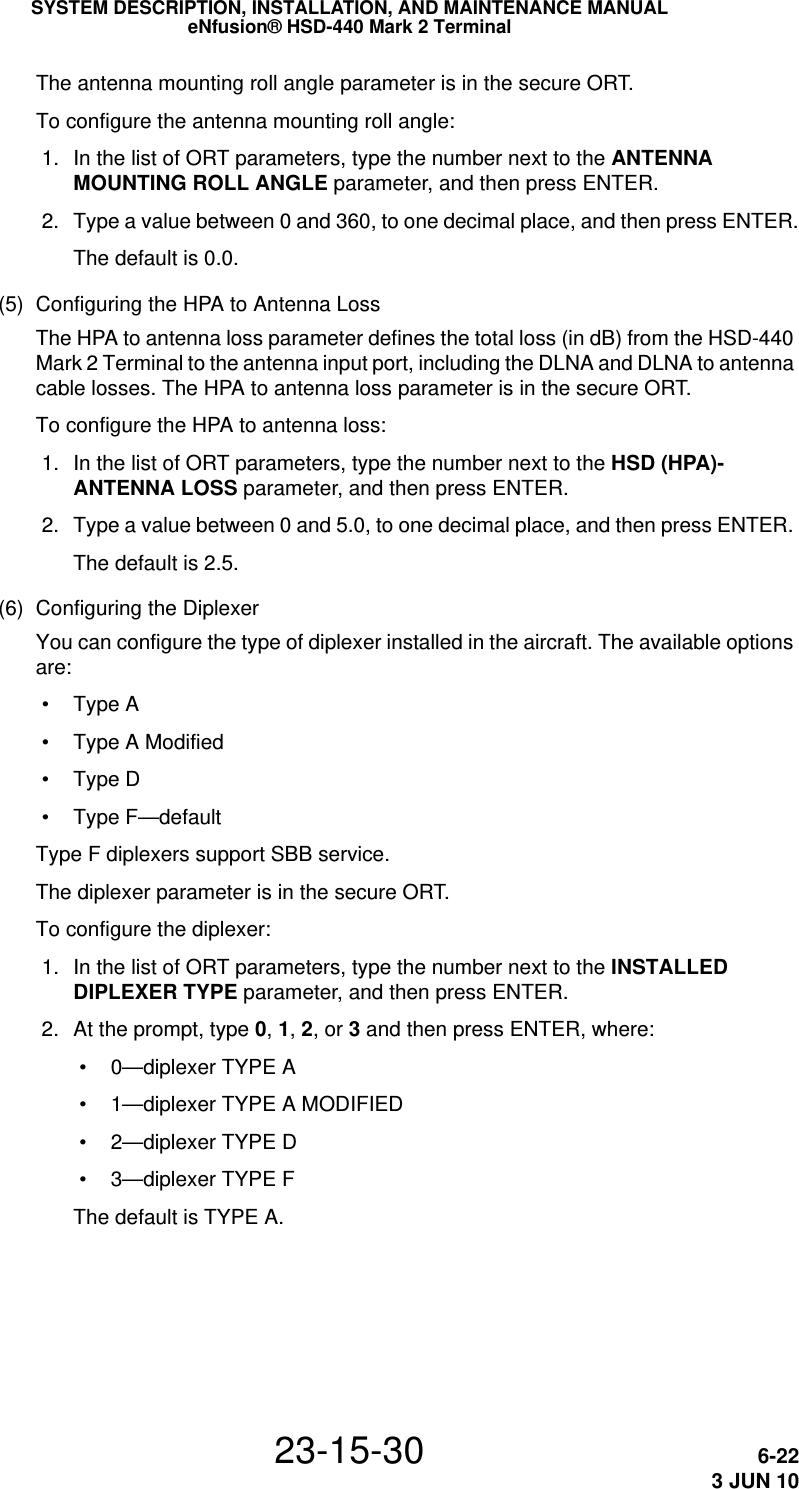
![SYSTEM DESCRIPTION, INSTALLATION, AND MAINTENANCE MANUALeNfusion® HSD-440 Mark 2 Terminal23-15-30 2-133 JUN 10 • * appears at the far left or right to indicate that pressing that key results in an action. • NUMBER/NUMBER appears to tell you which page out of how many pages you are viewing. For example, 1/3 would appear when you are on page 1 of 3 pages in total. • [ and ] appear around empty data fields where you can enter data. However, entering data is not mandatory in these fields.(6) Navigating the MCDUThe MCDU includes a number of menus, as shown in Figure 2-4. There are four category pages in the address book and up to 25 pages (100 phone numbers) for each category.NOTE: The SATCOM CH 2 STAT menu is not present when the HSD-440 Mark 2 Terminal is operating in SBB mode.Figure 2-4 MCDU Menus](https://usermanual.wiki/EMS-Technologies-Canada/HSD-MK2/User-Guide-1306479-Page-65.png)
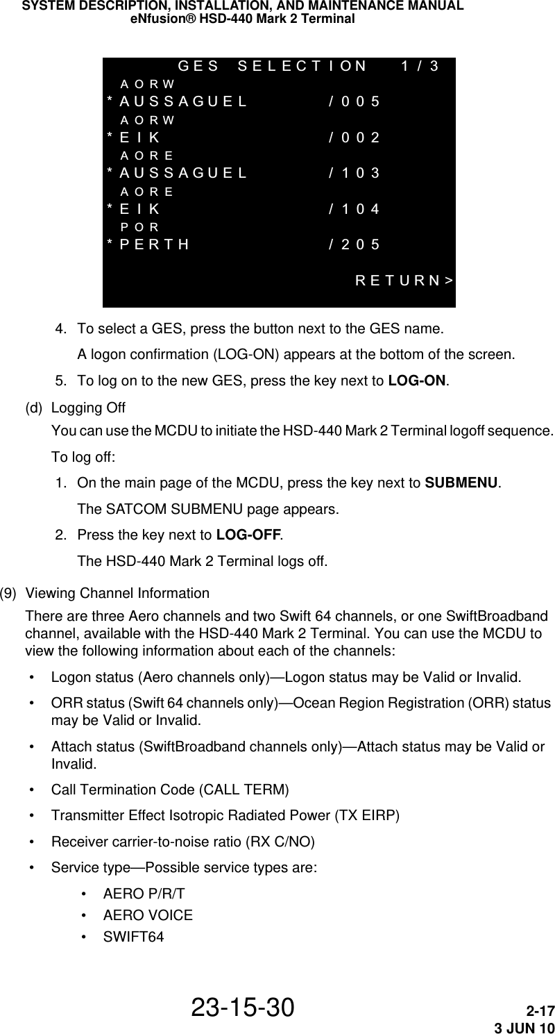
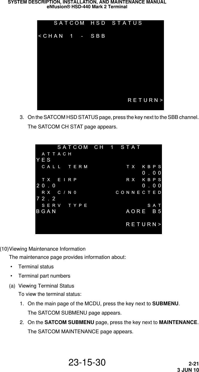
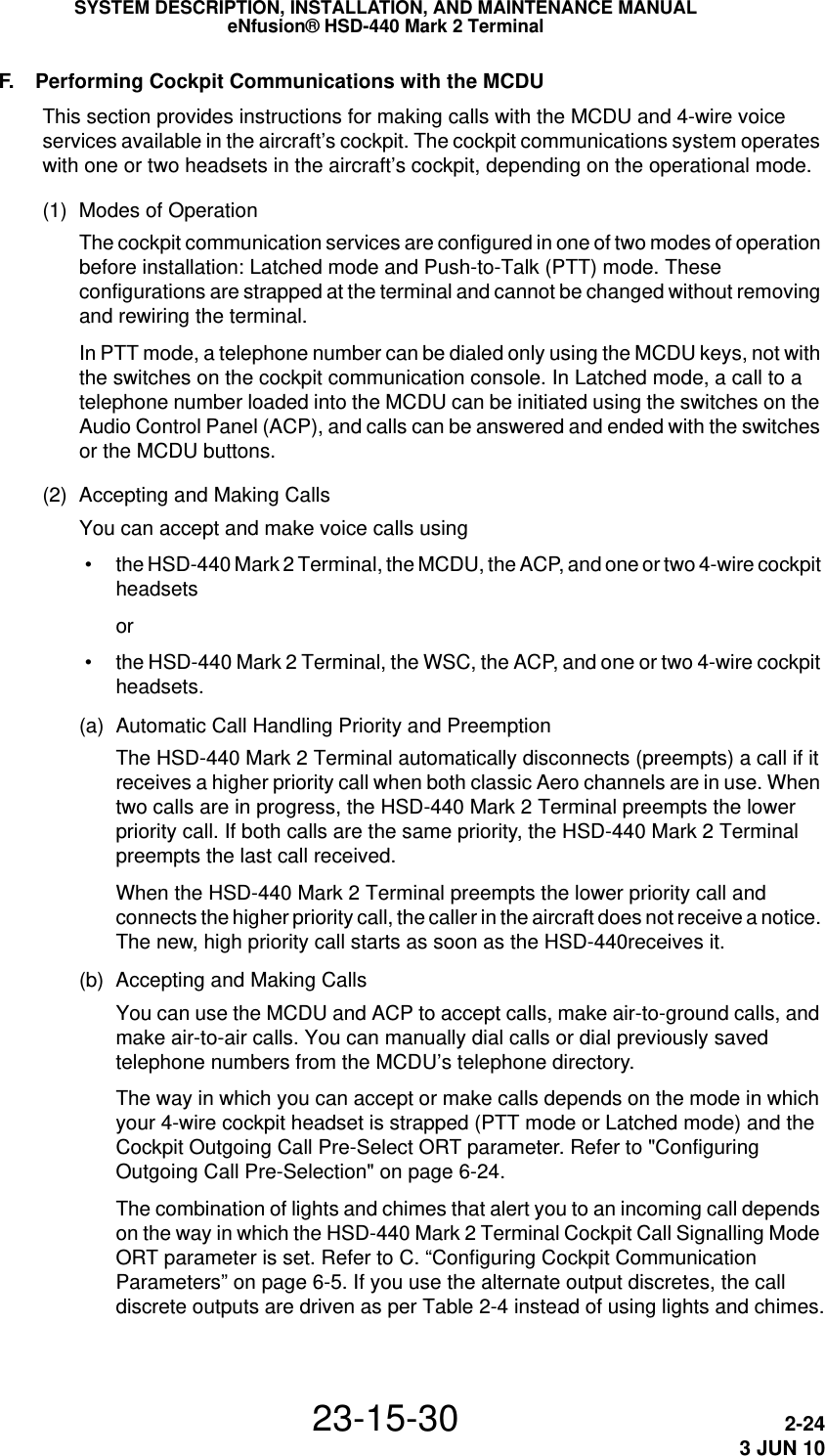
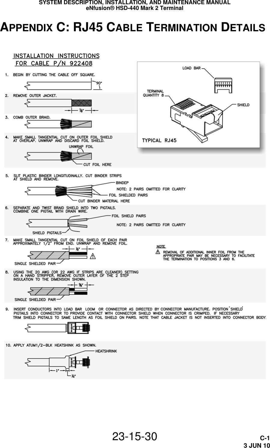
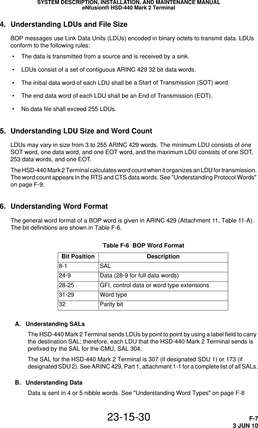
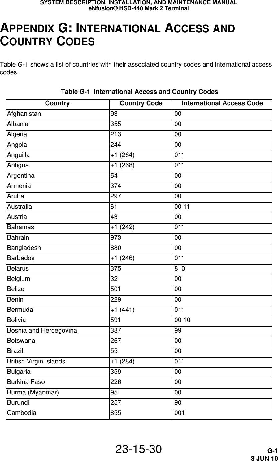
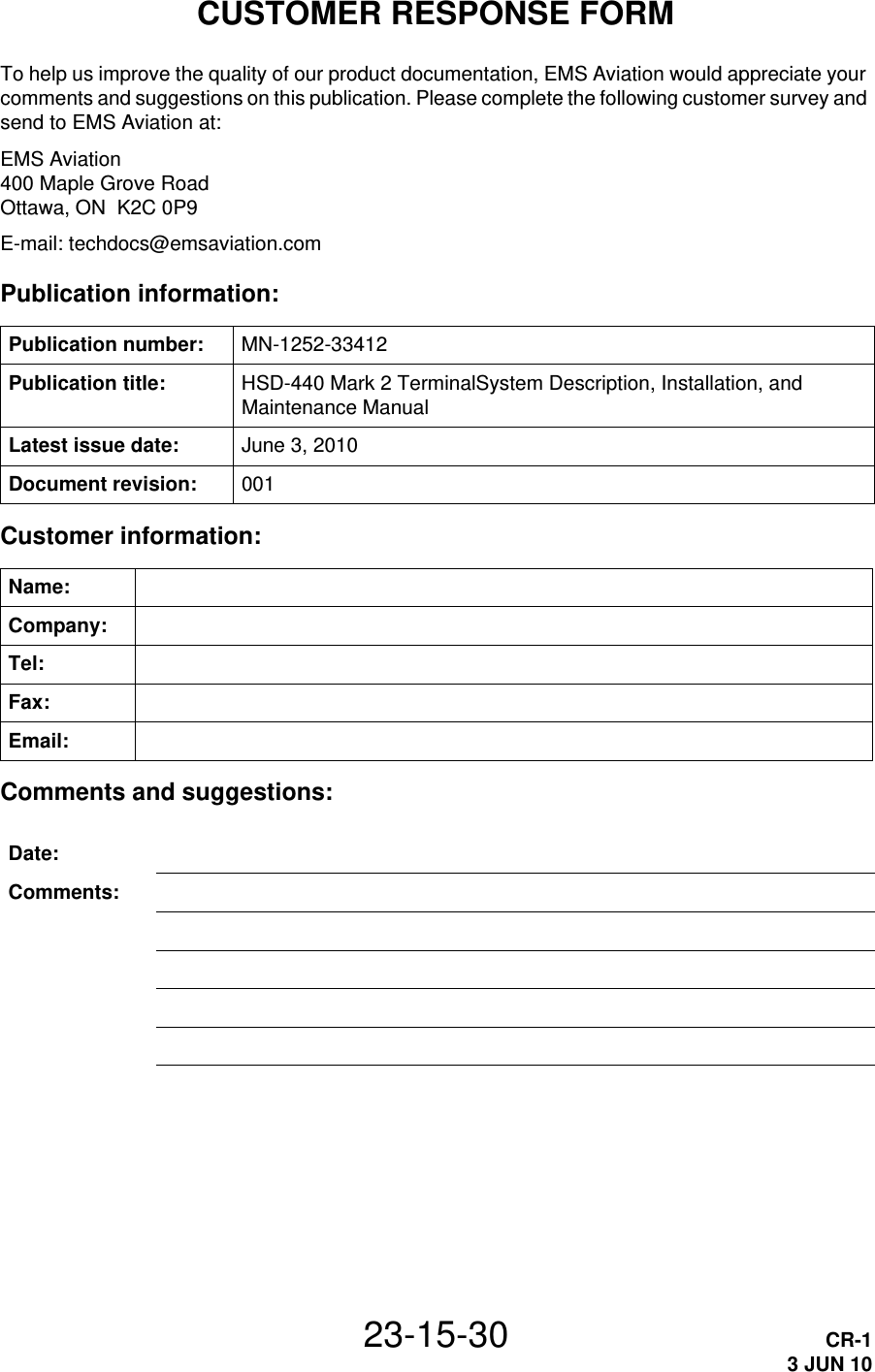
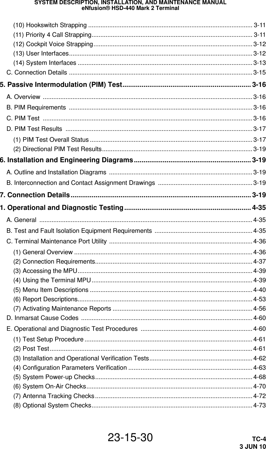
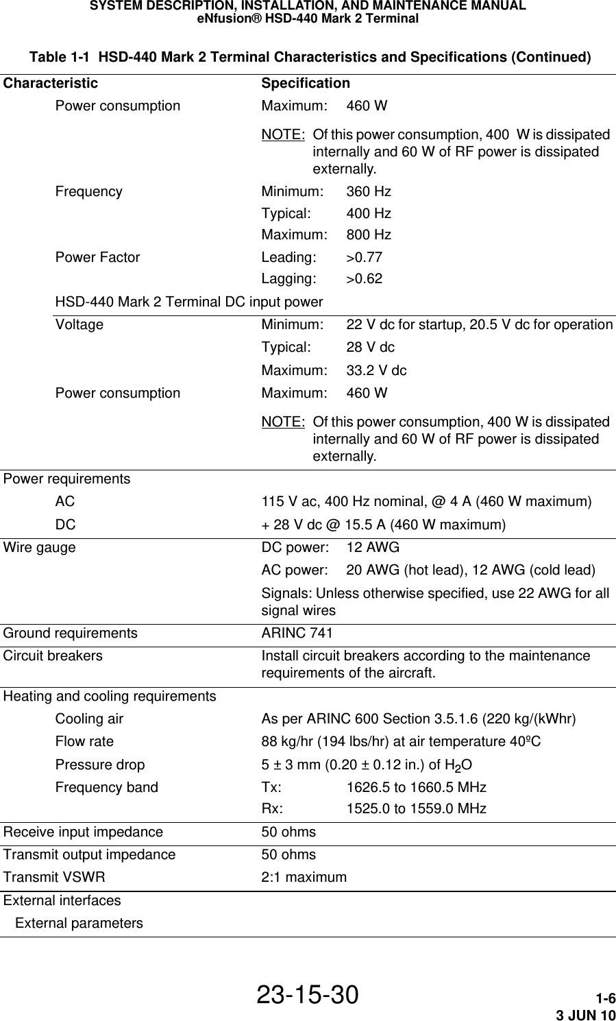
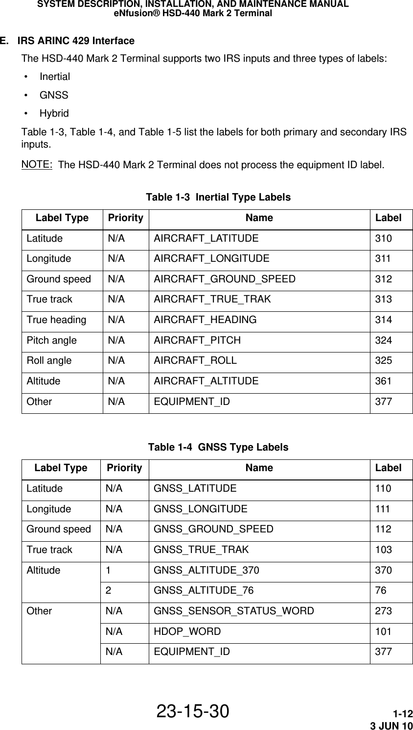
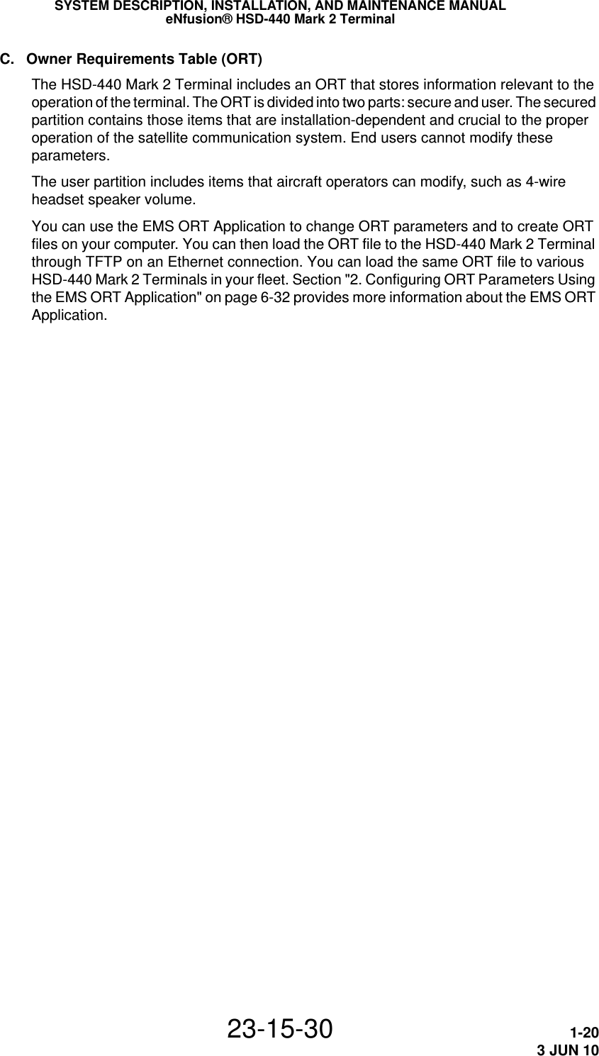
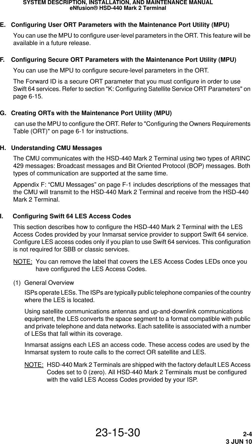
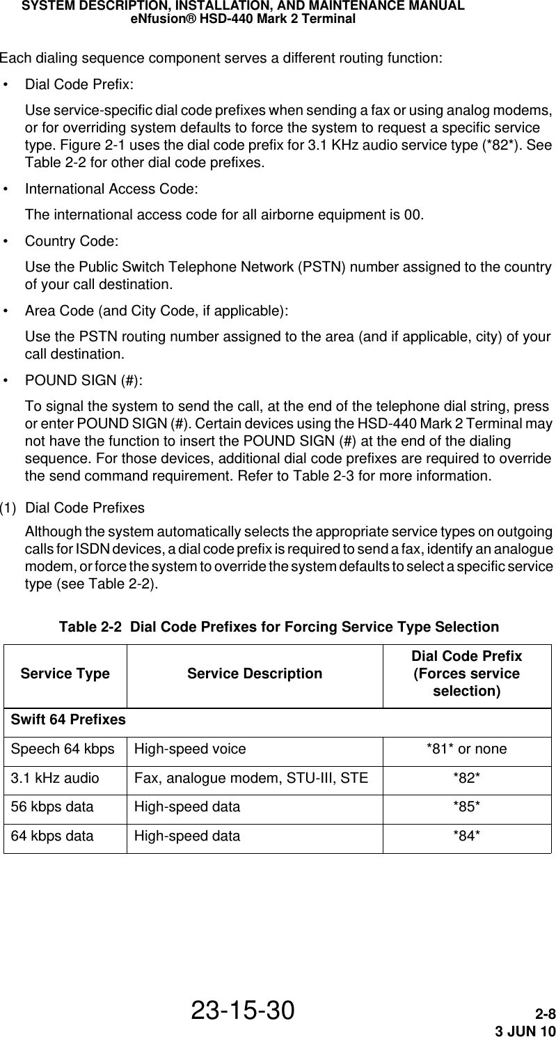
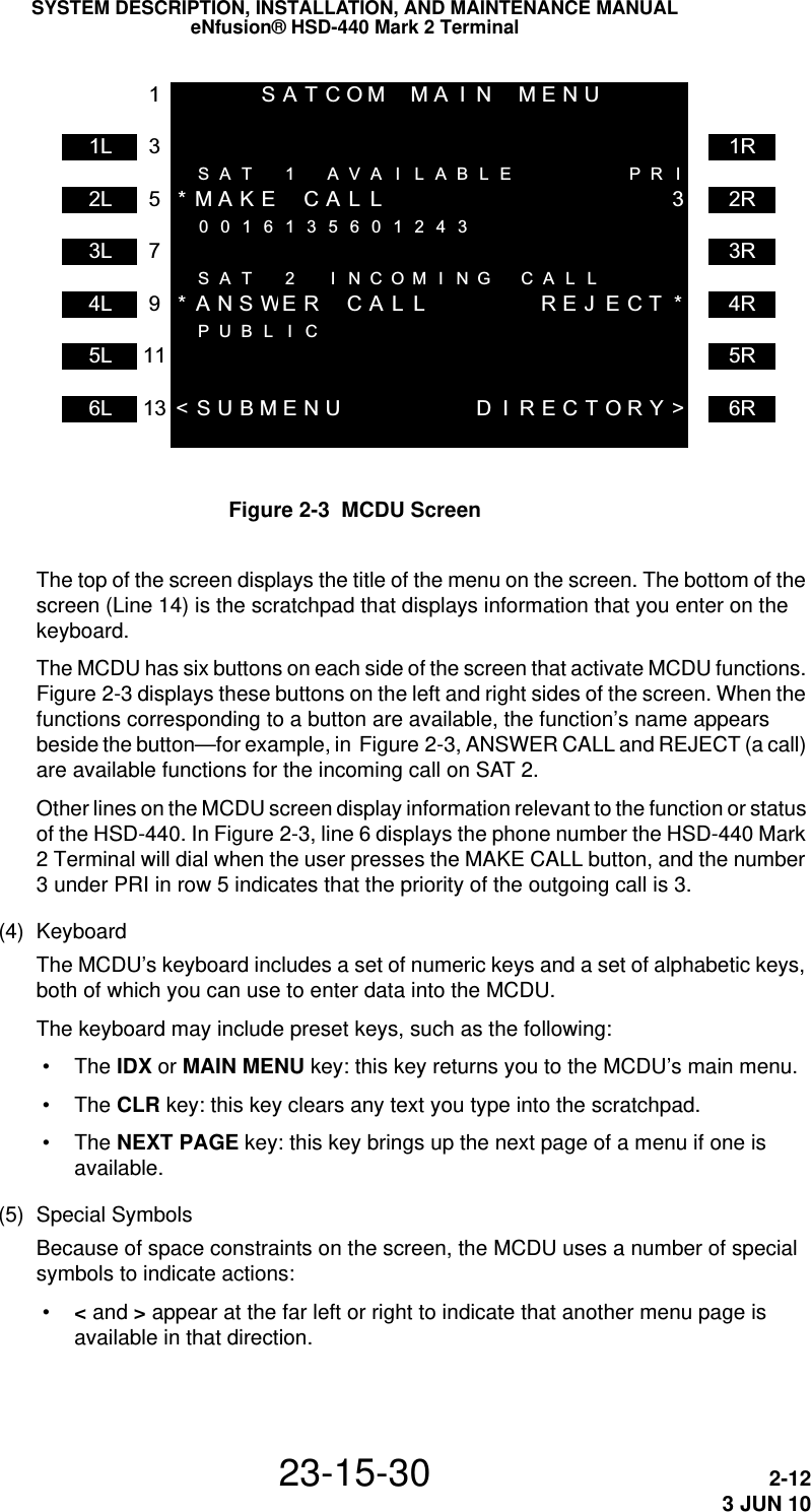
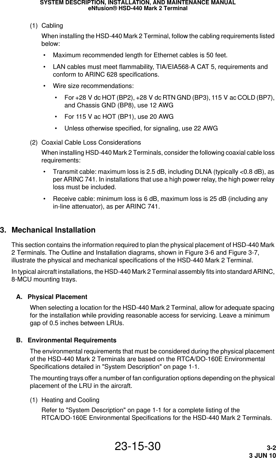
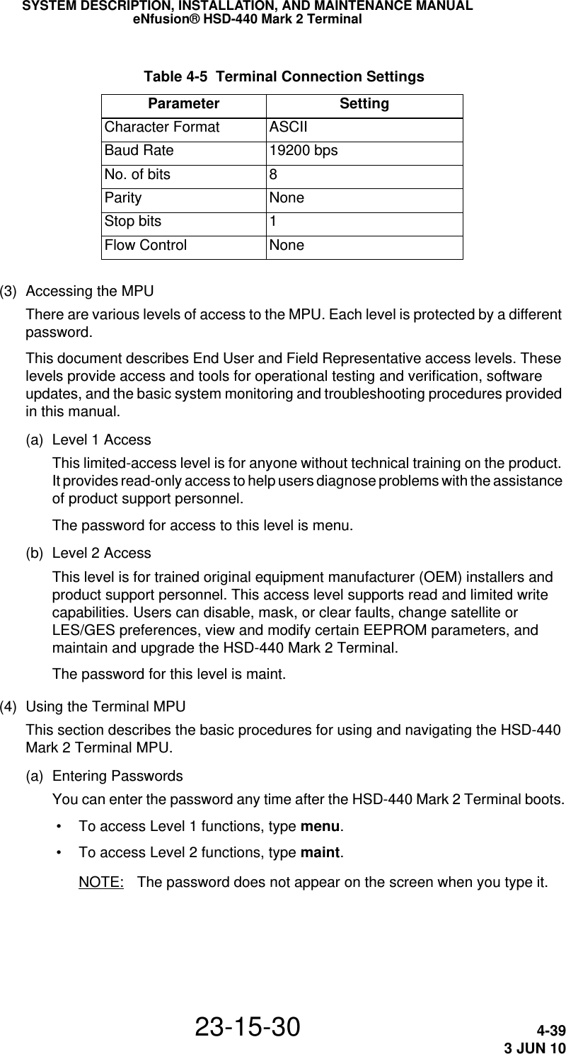
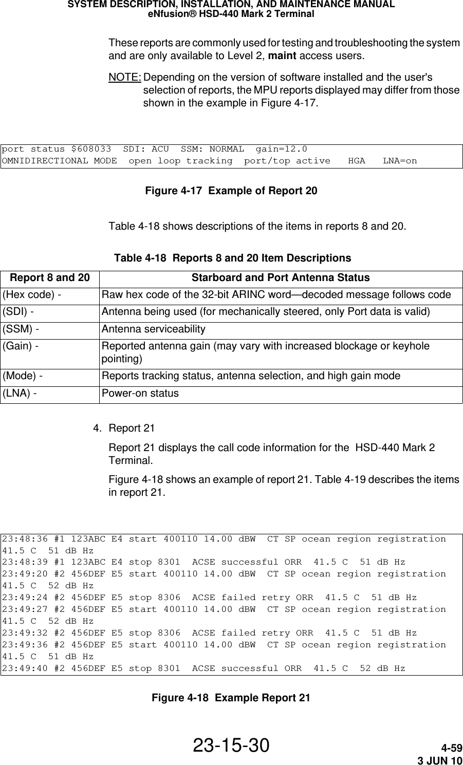
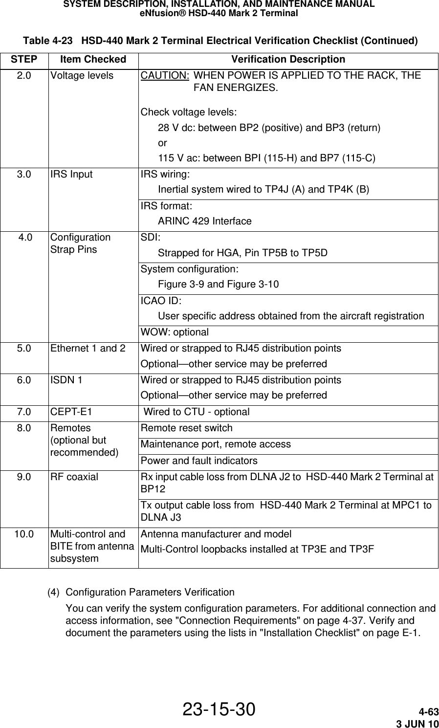
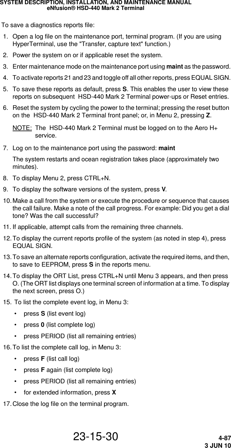
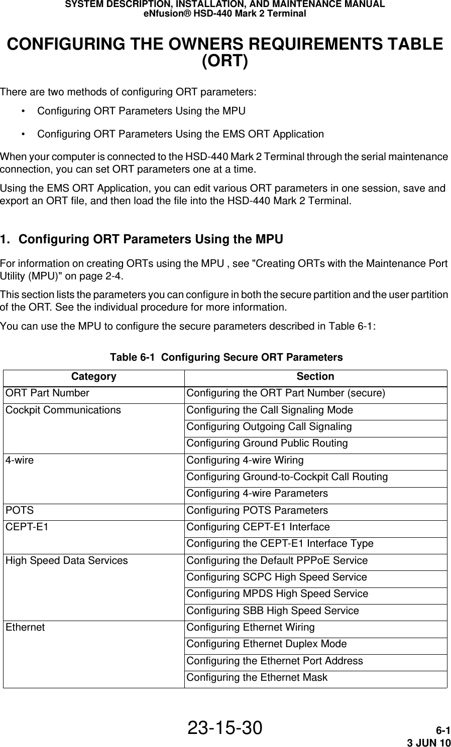
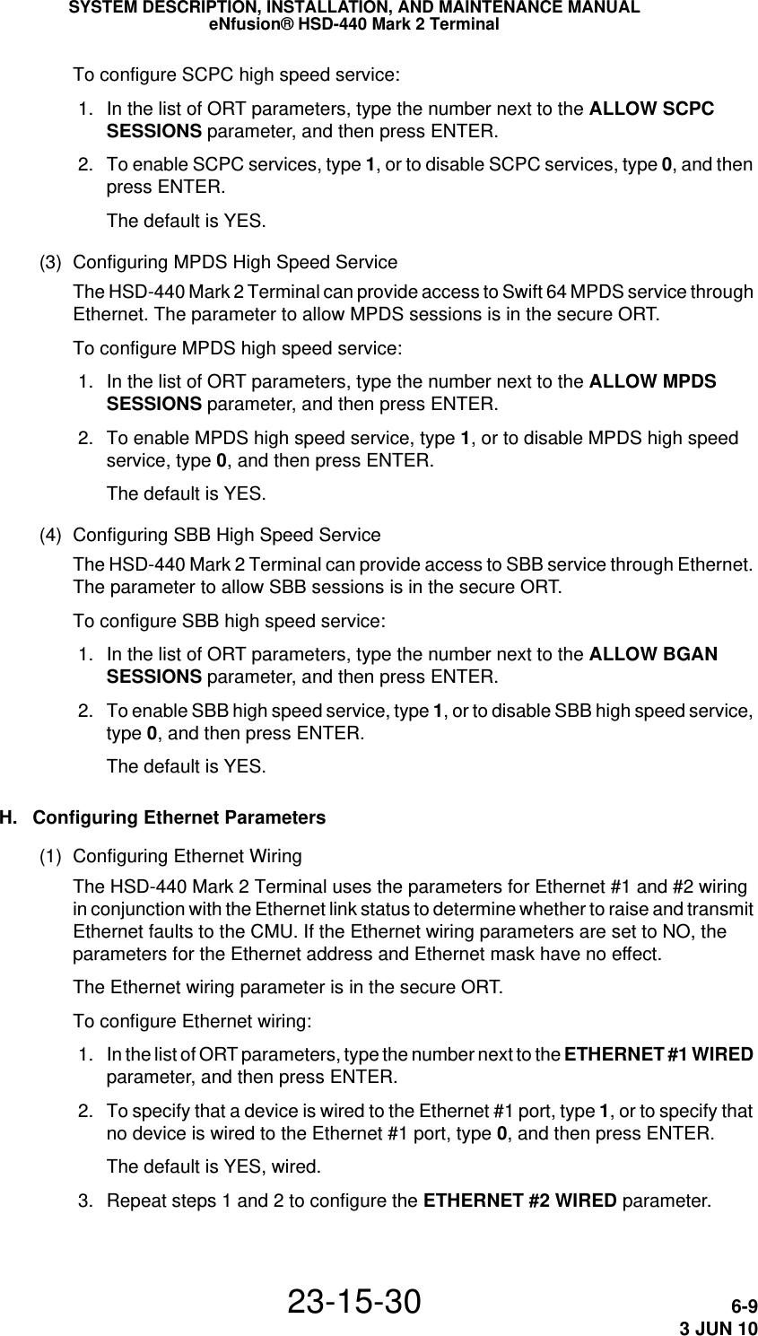
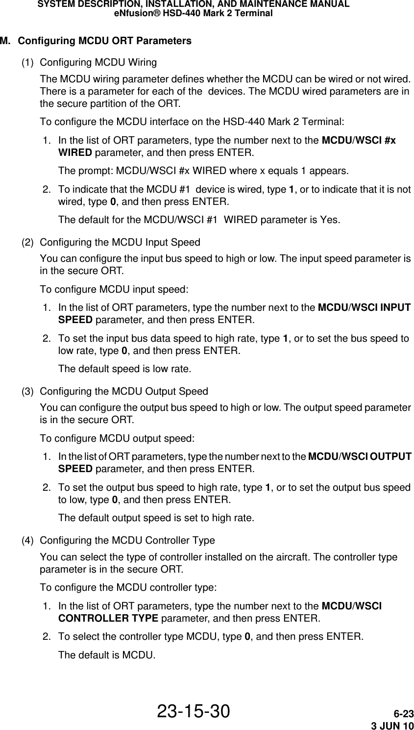
![SATCOMDIRECTORY<CATEGORY0 1 CATEGORY0 3 ><CATEGORY0 2 CATEGORY0 4 >SAT2[ MANUAL D I AL ] PR I3RETURN>SYSTEM DESCRIPTION, INSTALLATION, AND MAINTENANCE MANUALeNfusion® HSD-440 Mark 2 Terminal23-15-30 2-263 JUN 10 2. To select a channel, on the SATCOM DIRECTORY page, press the key next to SAT (the channel number). 3. To set the priority for your call using Table 2-5, type the priority number on the MCDU scratchpad and press the key next to PRI (the priority value). Table 2-5 Priority CodesCall priority Description1Emergency—used for distress or urgent calls2Operational-High—used for Flight Safety communications3Operational-Lo—used for Regularity of Flight, Meteorological or Administrative communications4Non-Operational—used for Non Safety of Flight or public phone call (cabin) communications 4. To dial the call, type the phone number into the scratchpad and press the key next to MANUAL DIAL.With Pre-Select Mode disabled, the MCDU Main Menu page appears and the HSD-440 Mark 2 Terminal initiates the call. With Pre-Select Mode enabled, the MCDU Main Menu page appears. • To start the call with Pre-Select mode enabled, in either Latched or PTT mode, press the key next to MAKE CALL. • To start the call in PTT mode with Pre-Select mode enabled, on the ACP, assert the PLACE/END CALL 1 or PLACE/END CALL 2 switch. or assert the SAT 1 or SAT 2 switch and then press the PTT switch. • To start the call In Latched mode with Pre-Select mode enabled, on the ACP, assert the SAT 1 or SAT 2 switch.](https://usermanual.wiki/EMS-Technologies-Canada/HSD-MK2/User-Guide-1306479-Page-78.png)
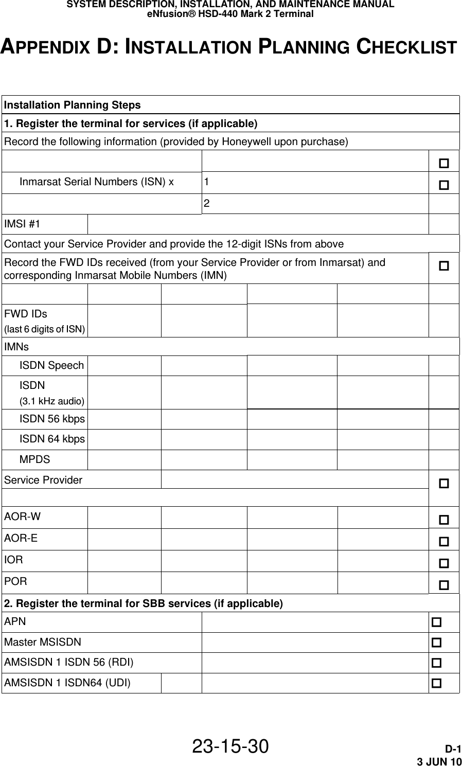
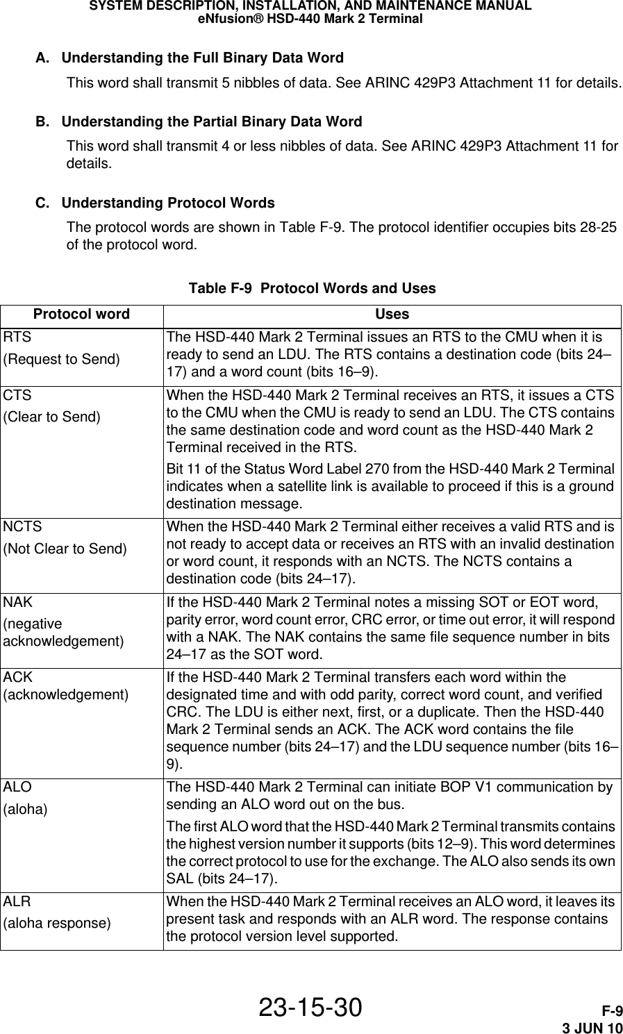
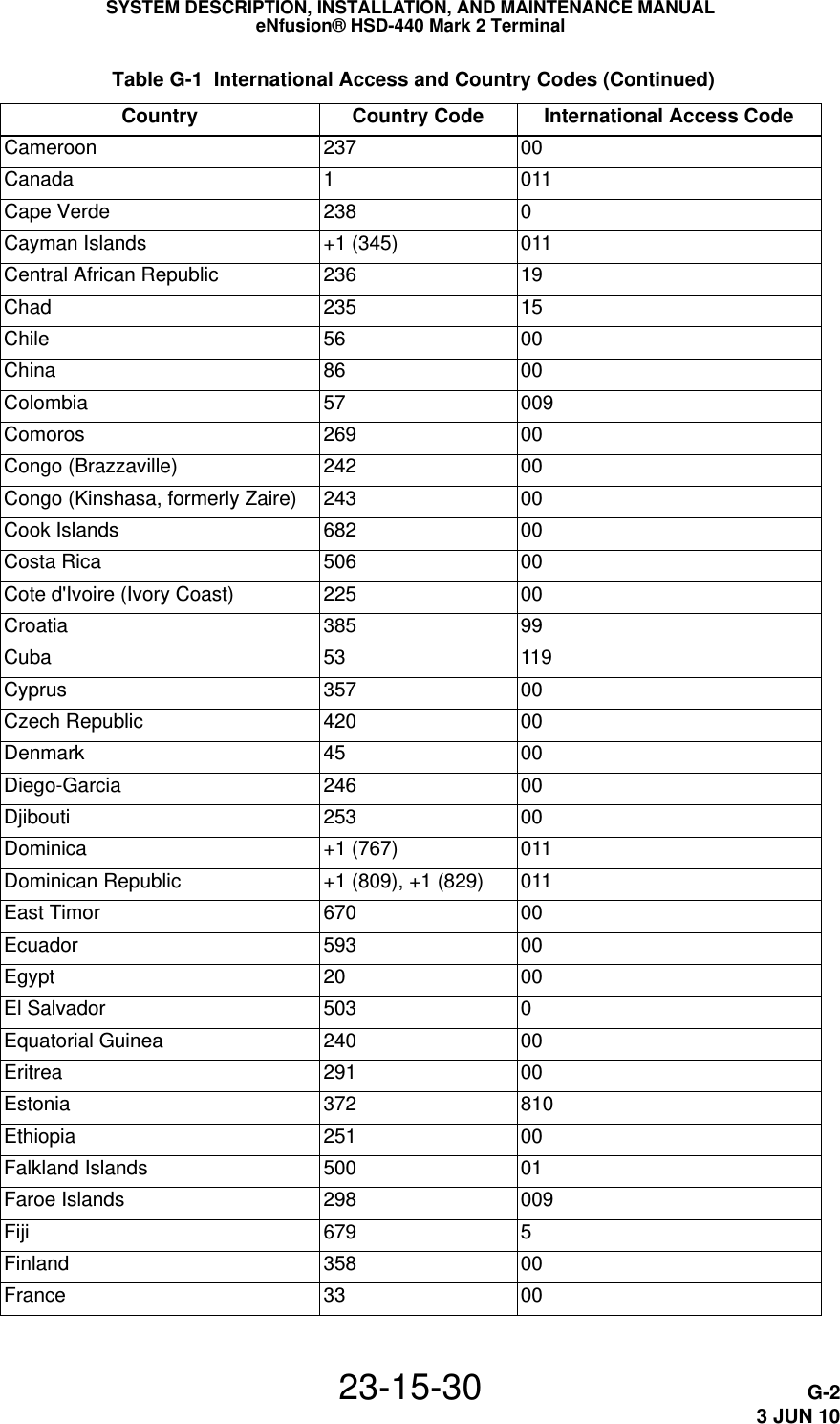
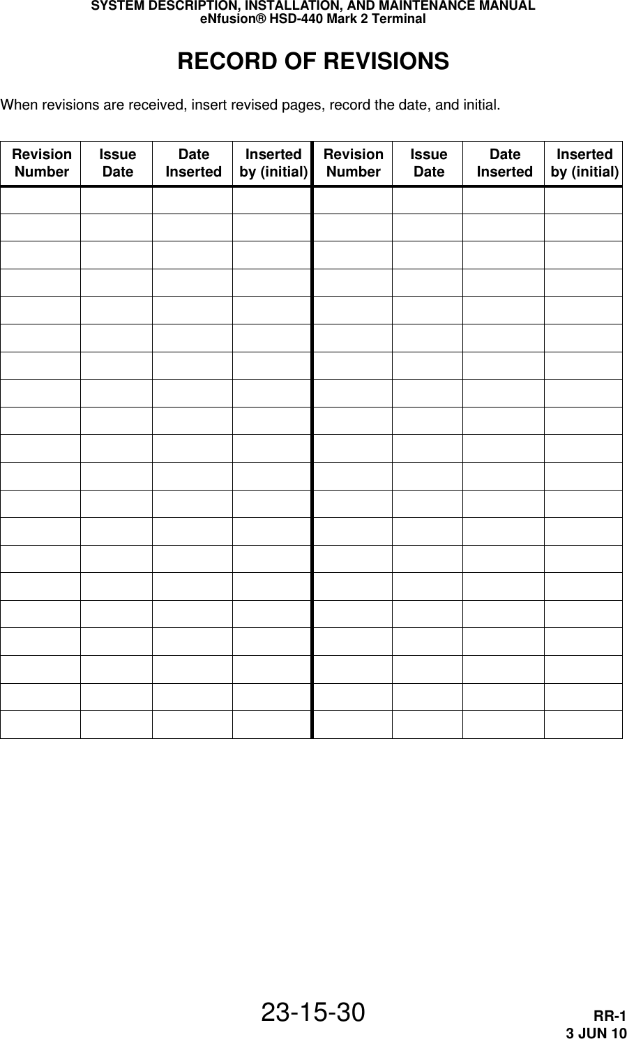
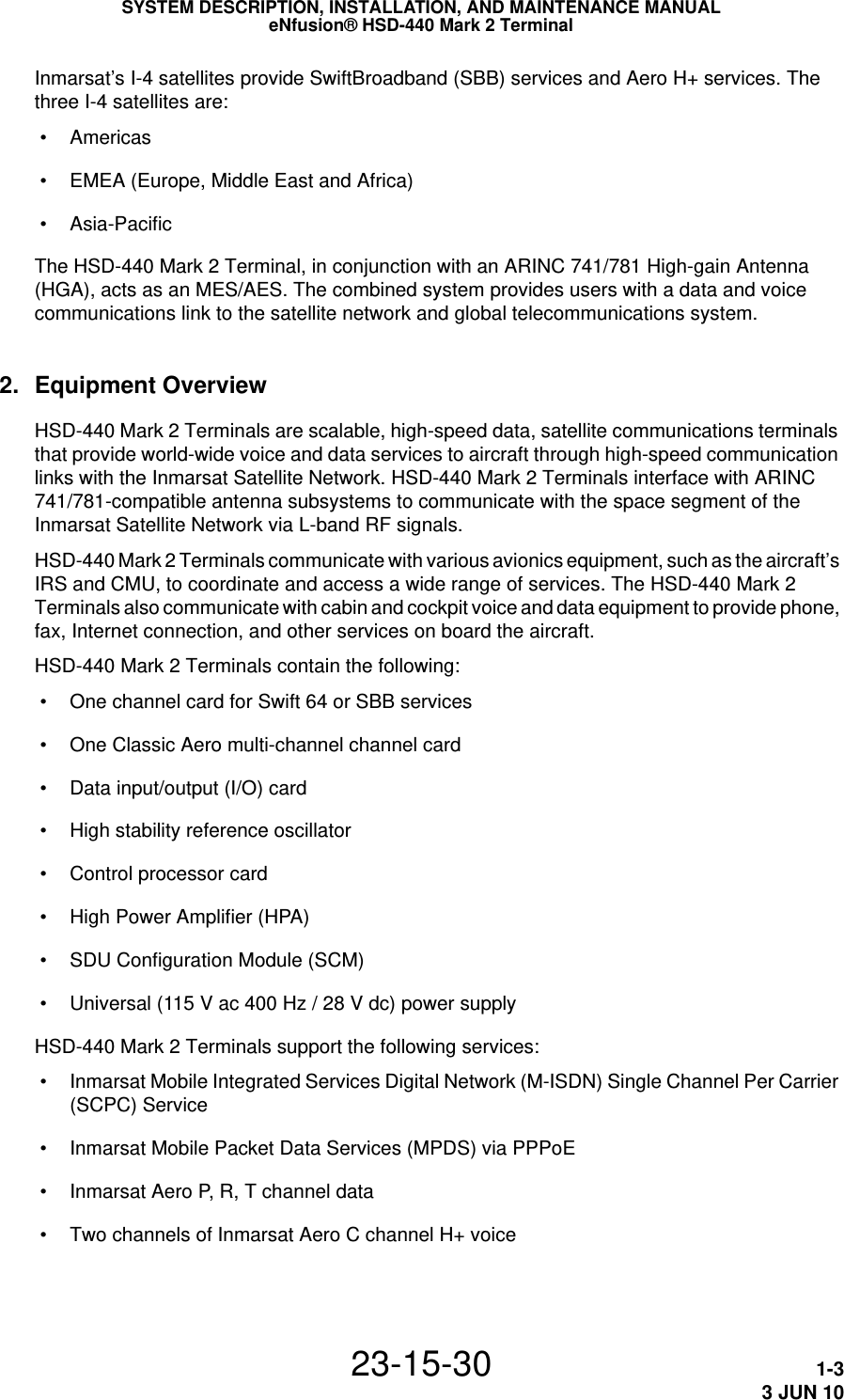
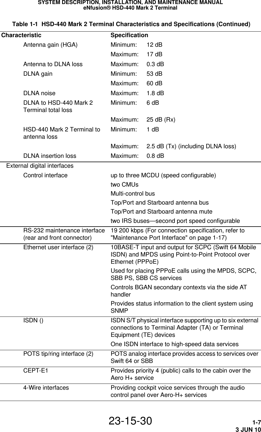
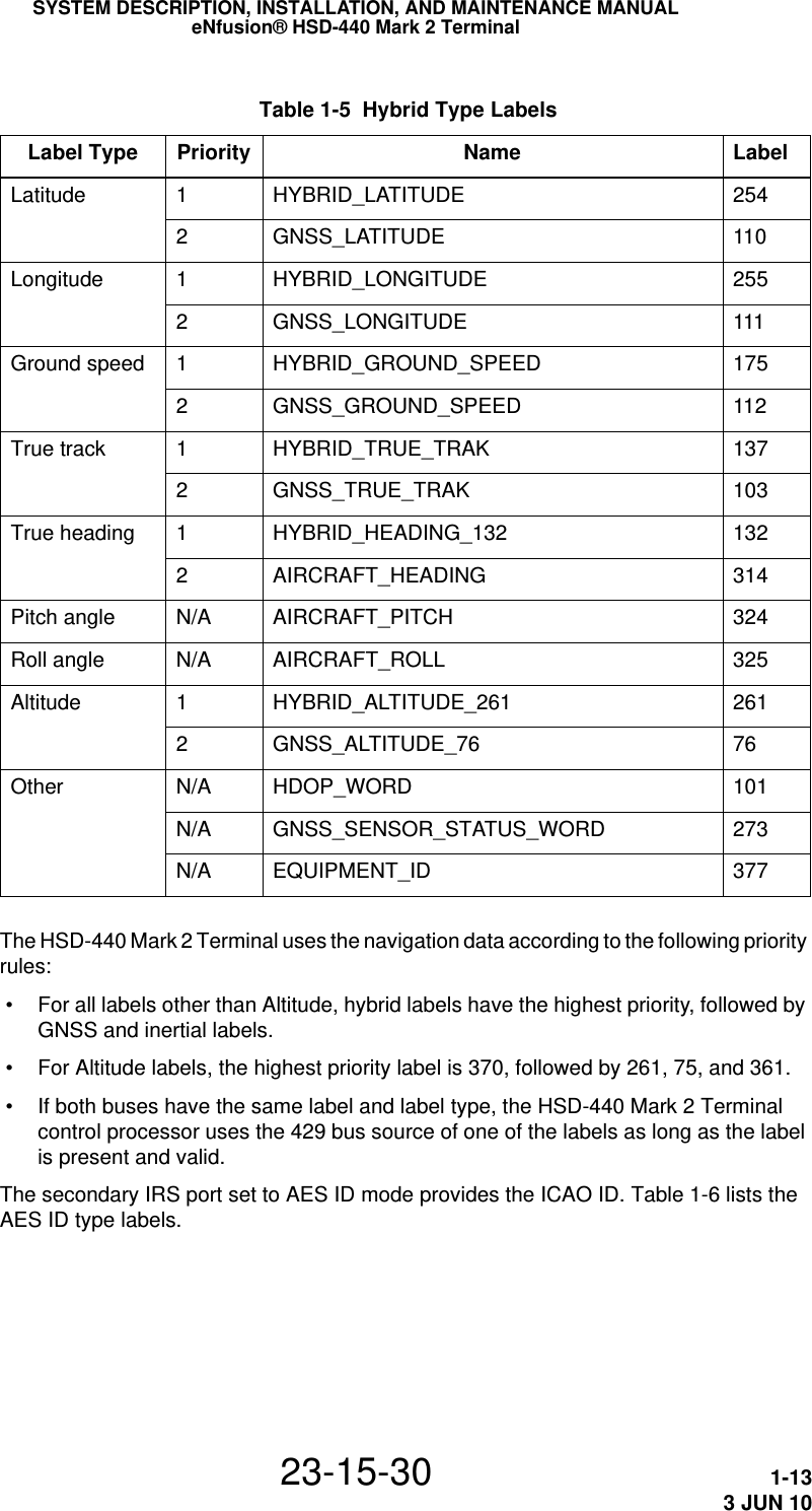
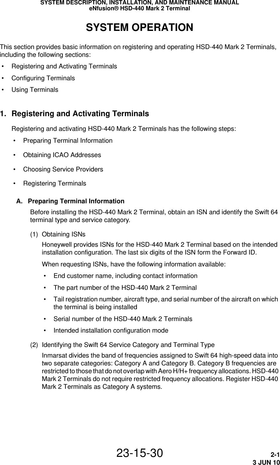
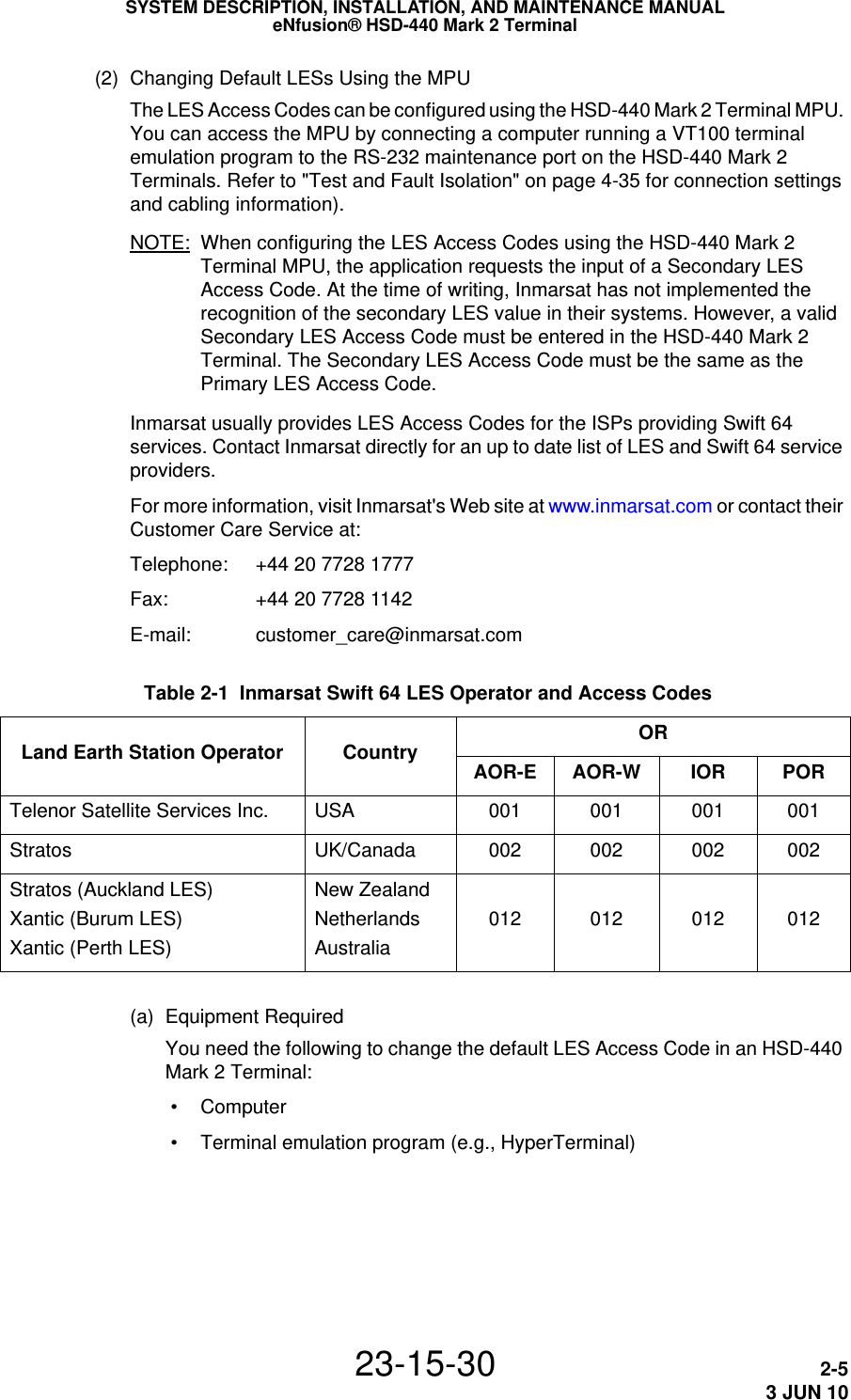
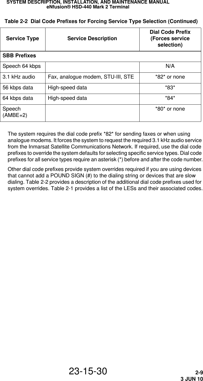
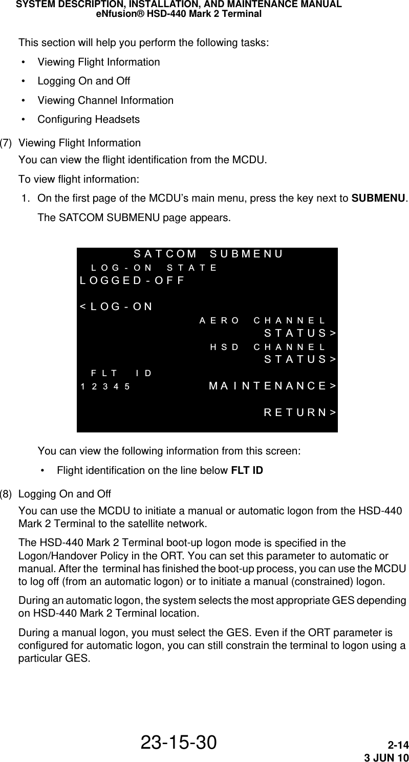
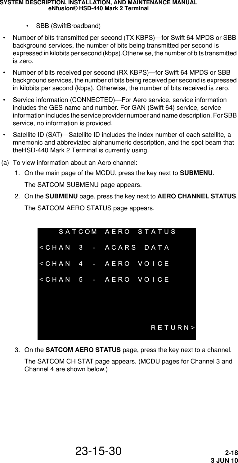
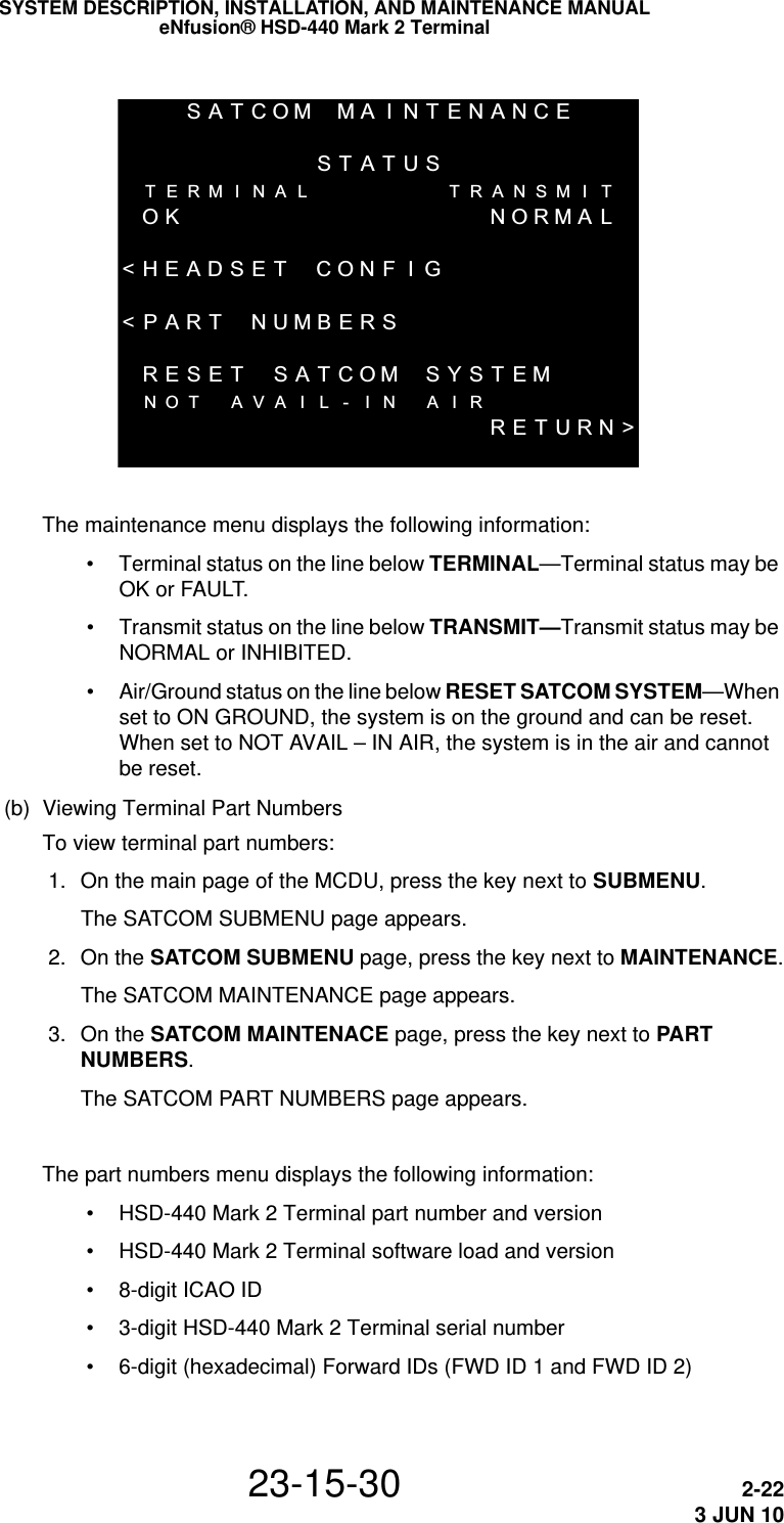
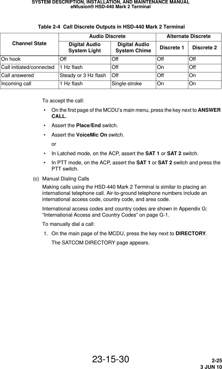
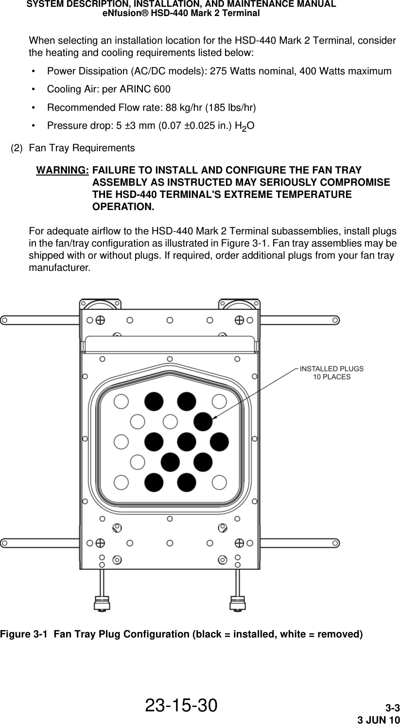
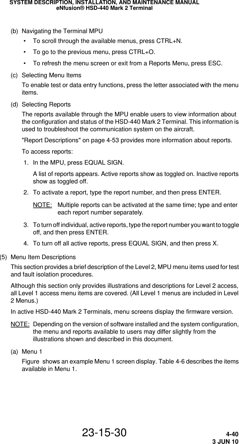
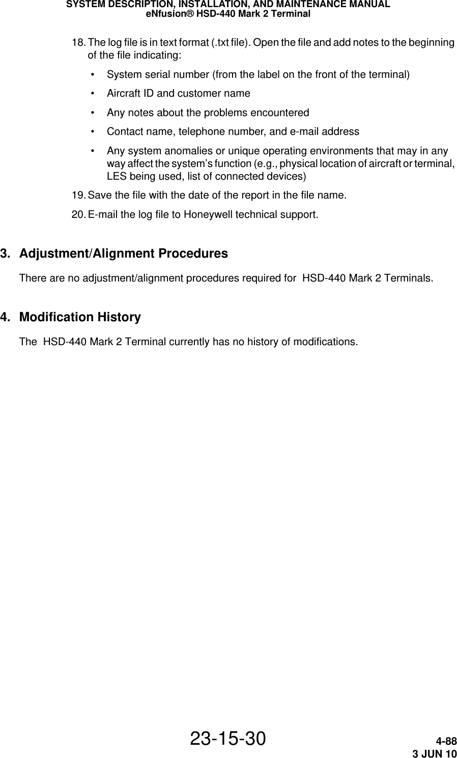
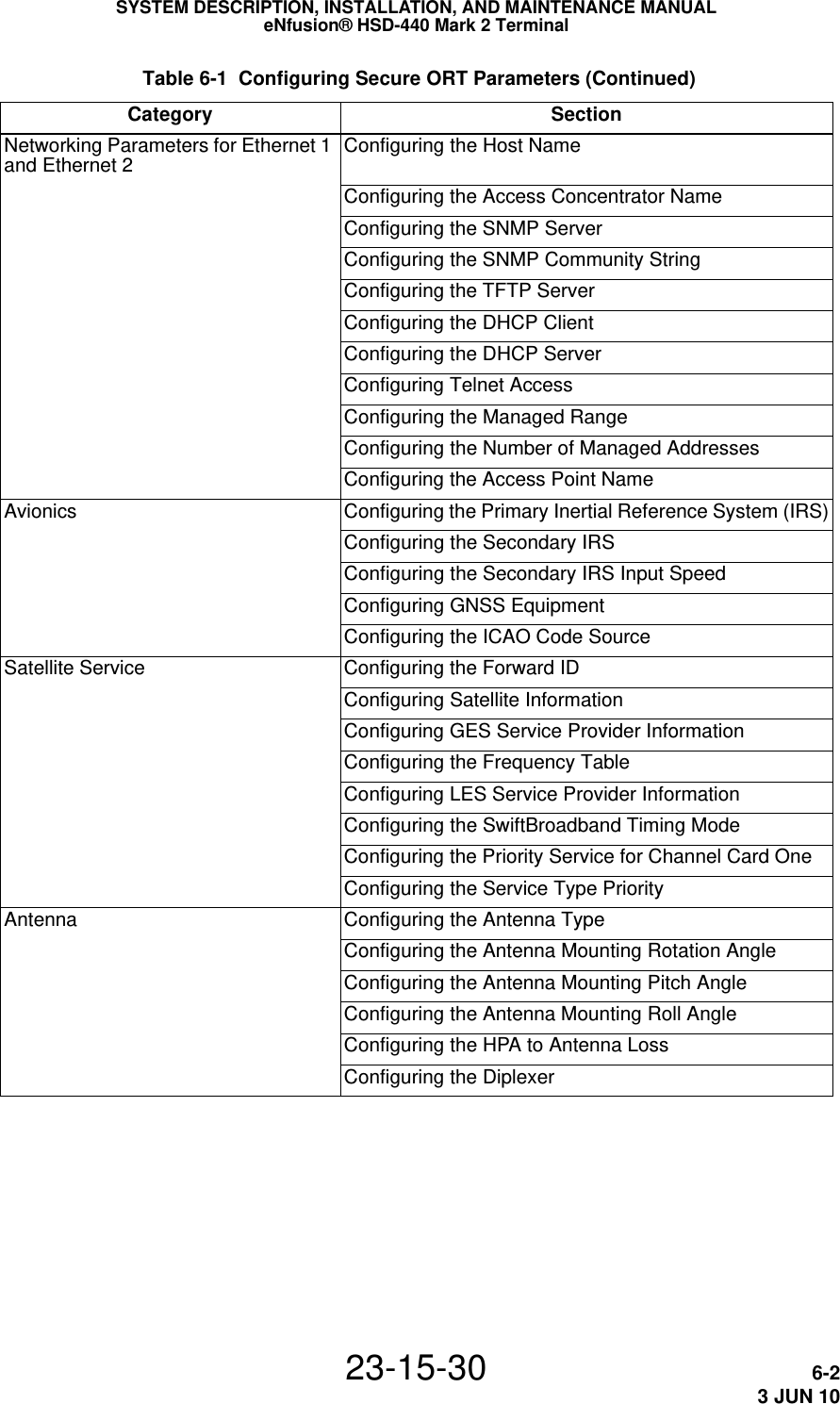
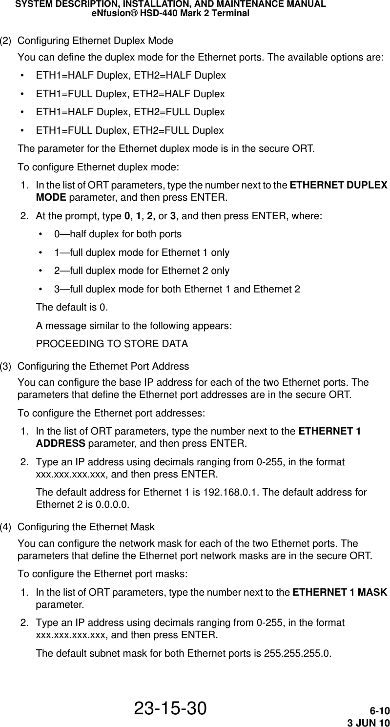
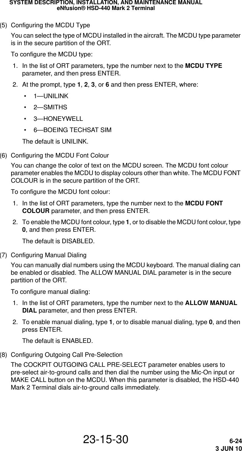
![SYSTEM DESCRIPTION, INSTALLATION, AND MAINTENANCE MANUALeNfusion® HSD-440 Mark 2 Terminal23-15-30 2-273 JUN 10(d) Making Calls from the Telephone DirectoryYou can make voice calls from the numbers you have saved in the MCDU’s telephone directory.The HSD-440 Mark 2 Terminal MCDU enables you to keep four separate telephone books for different uses. By default, these books are called Category 01, Category 02, Category 03, and Category 04. You can customize the directory names in the HSD-440 Mark 2 Terminal ORT.To make a call from the telephone directory: 1. On the main page of the MCDU, press the key next to DIRECTORY.The SATCOM DIRECTORY page appears.SATCOMDIRECTORY<CATEGORY0 1 CATEGORY0 3 ><CATEGORY0 2 CATEGORY0 4 >SAT2[ MANUAL D I AL ] PR I3RETURN> 2. To access the phone numbers in a directory, press the key next to the directory name.The selected directory appears.CATEGORY 1 1/1MAKE CAL L : SAT10116135551111 PRI* 01 - LABEL 1 30116135552222* 02 - LABEL 2 1[][][]* SORT RETURN>](https://usermanual.wiki/EMS-Technologies-Canada/HSD-MK2/User-Guide-1306479-Page-79.png)

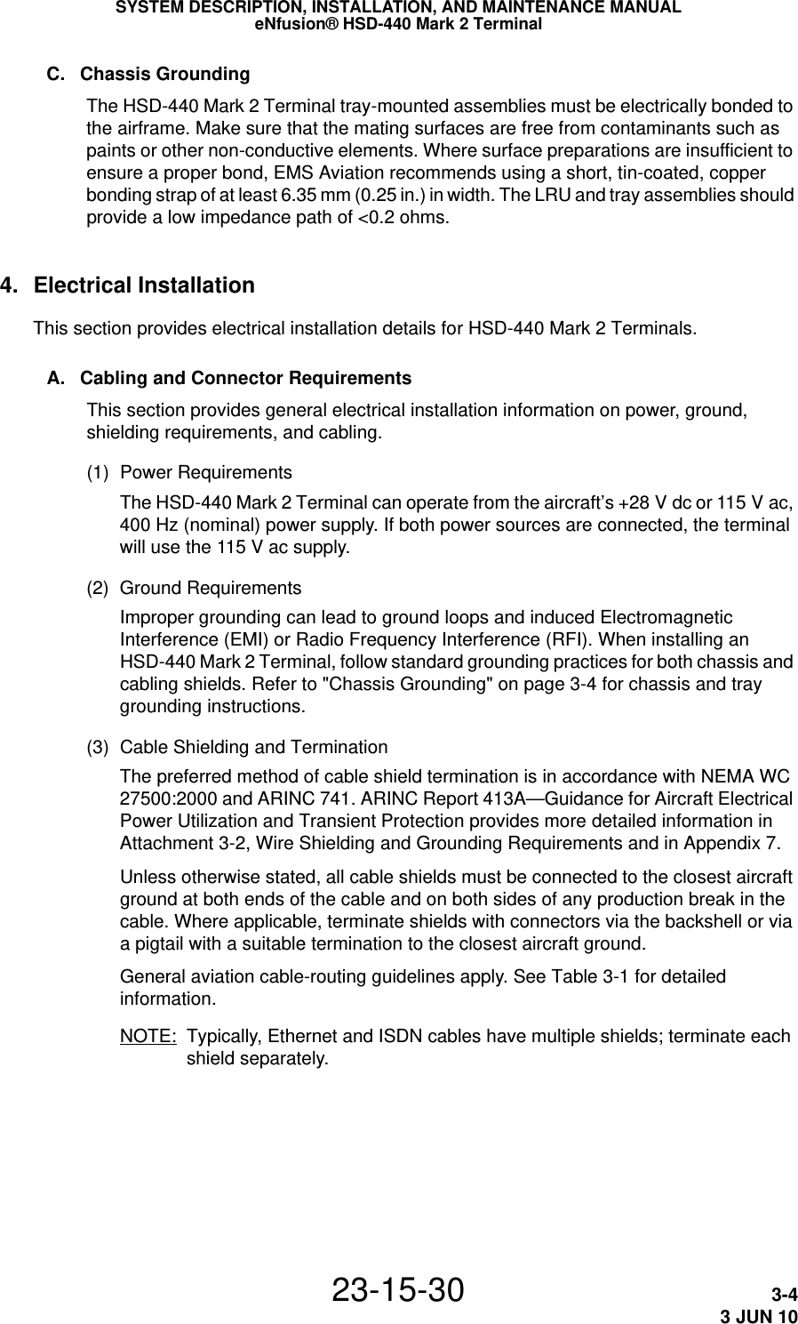


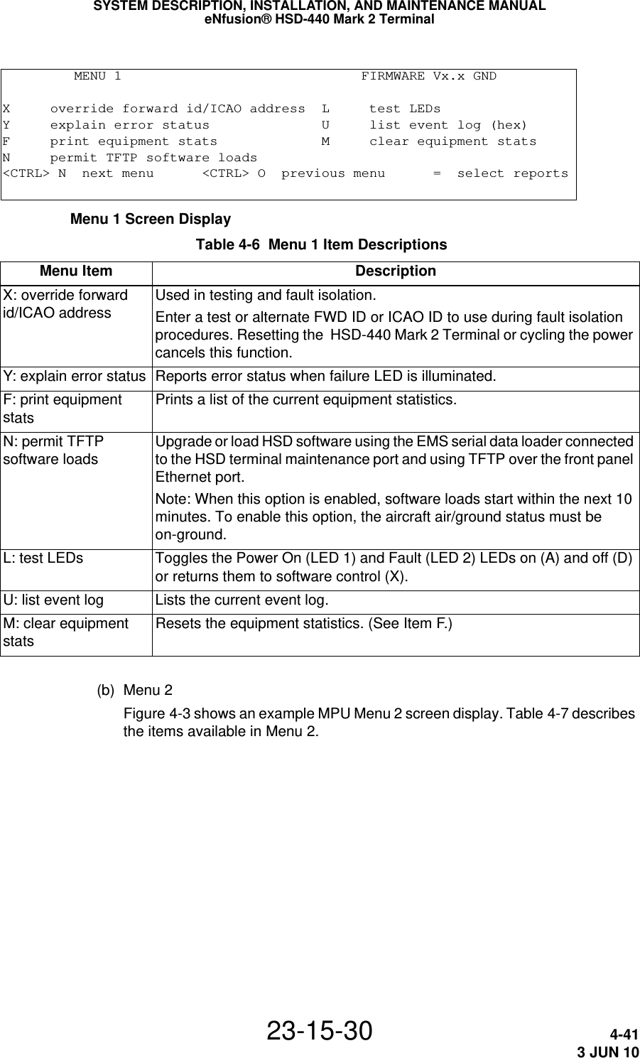
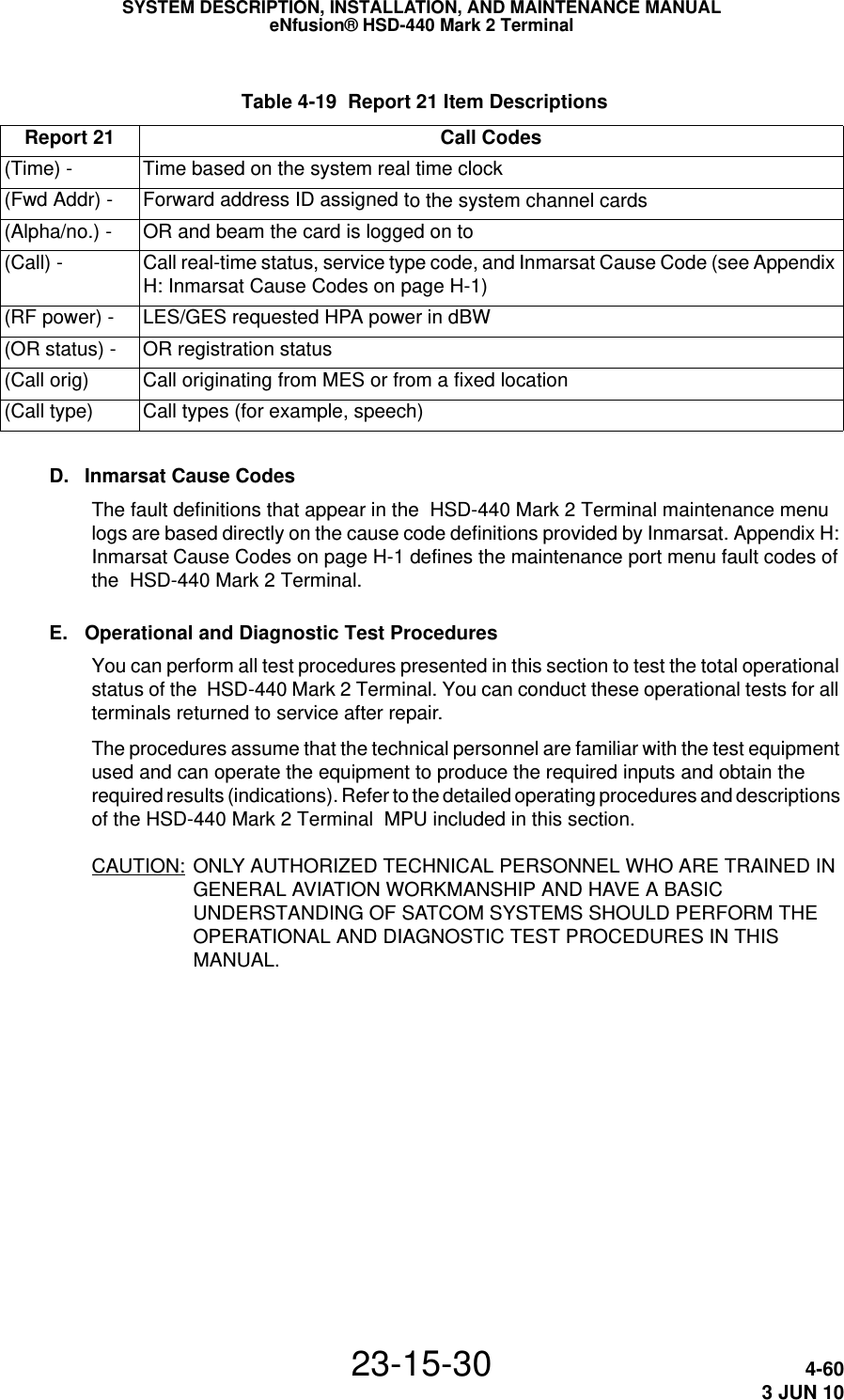
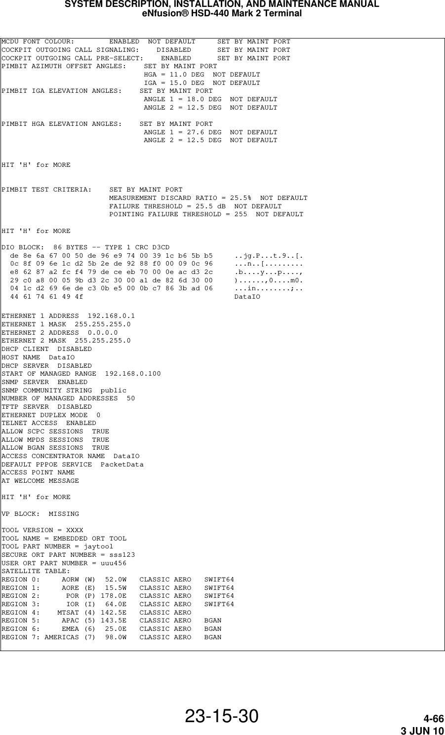
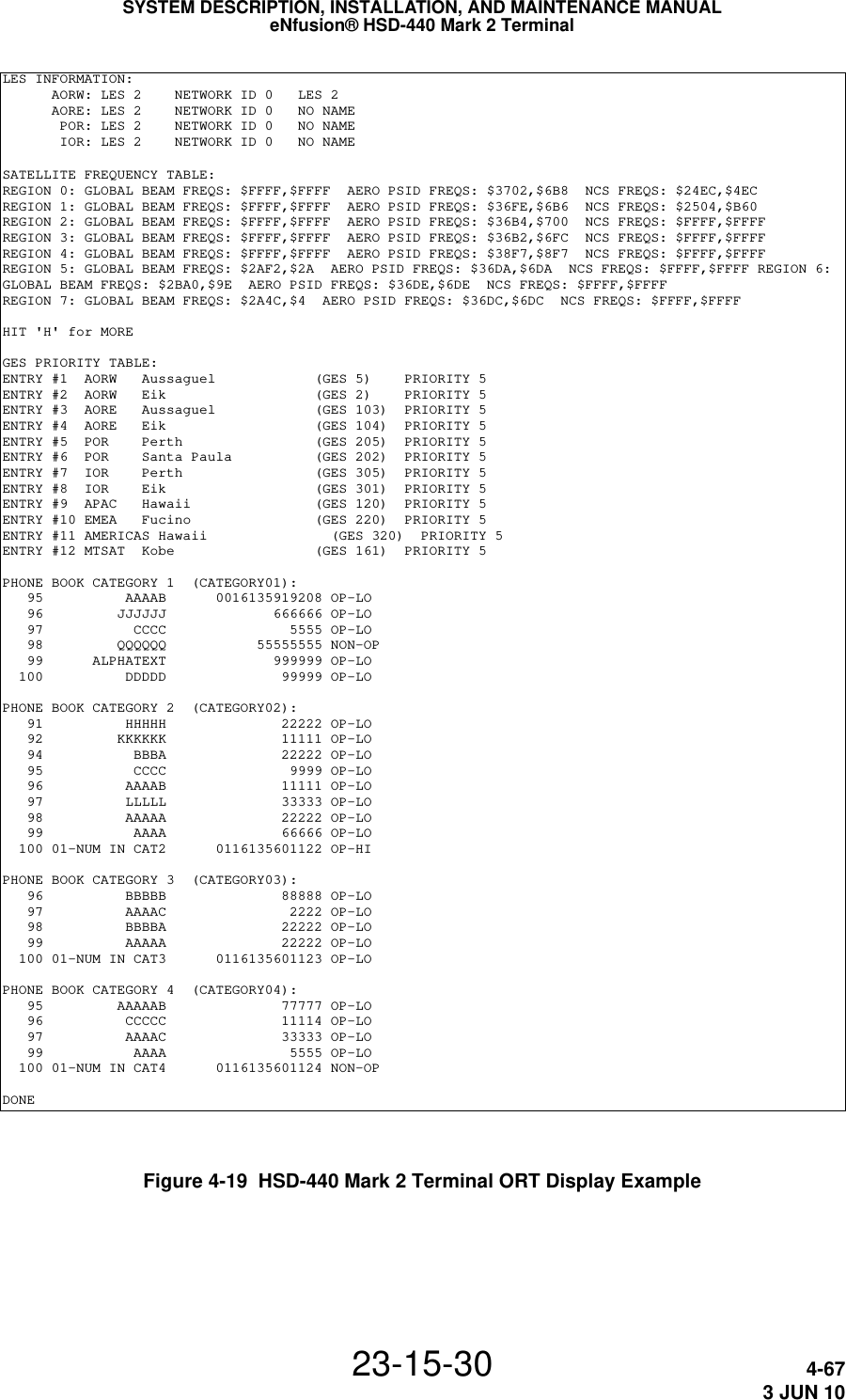
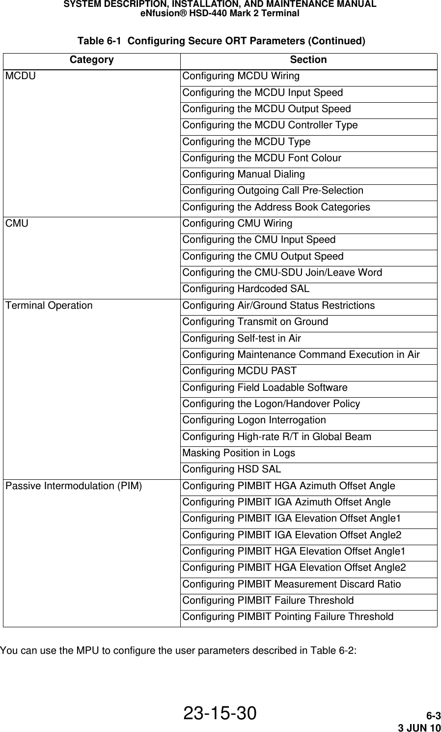
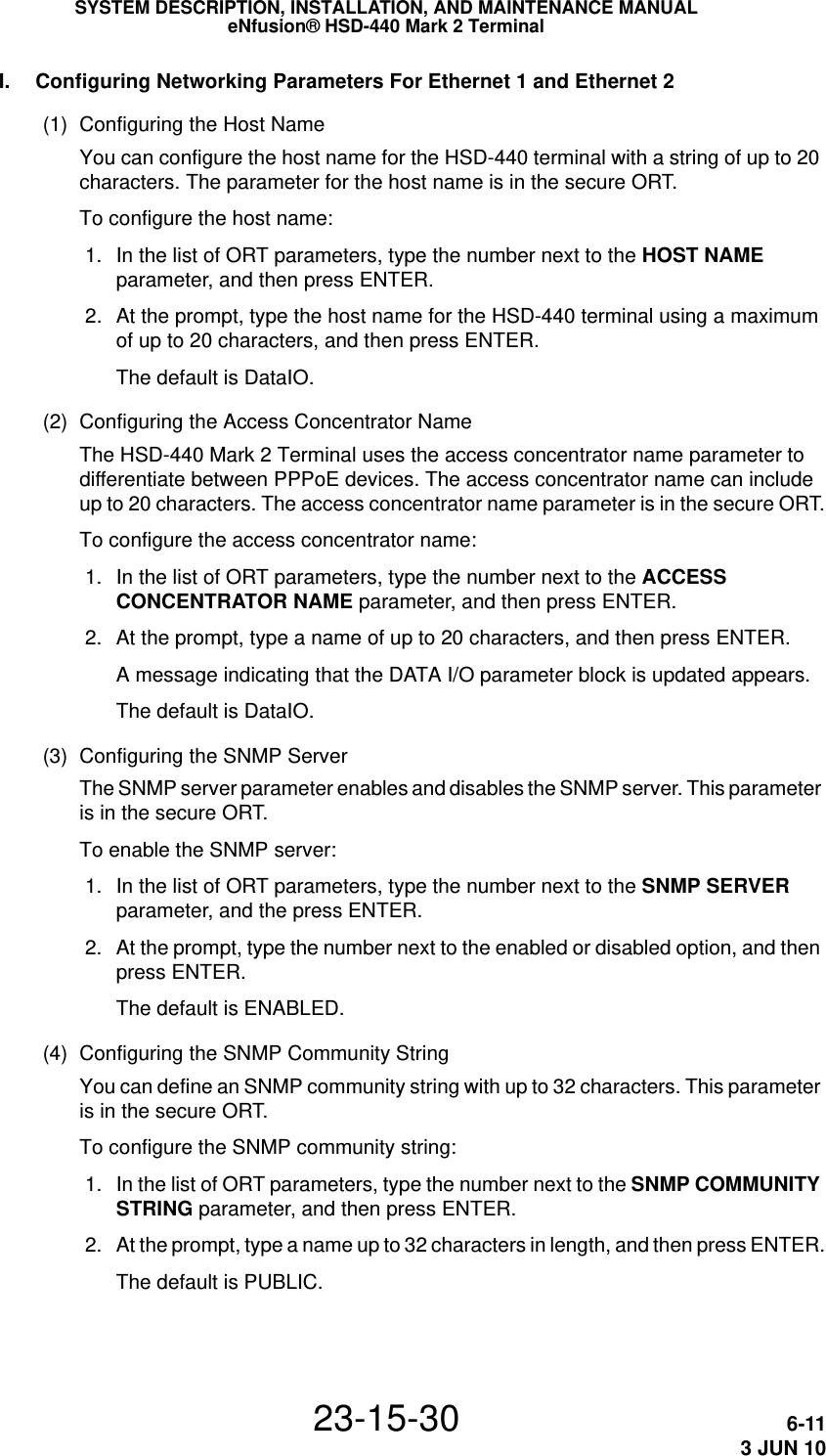
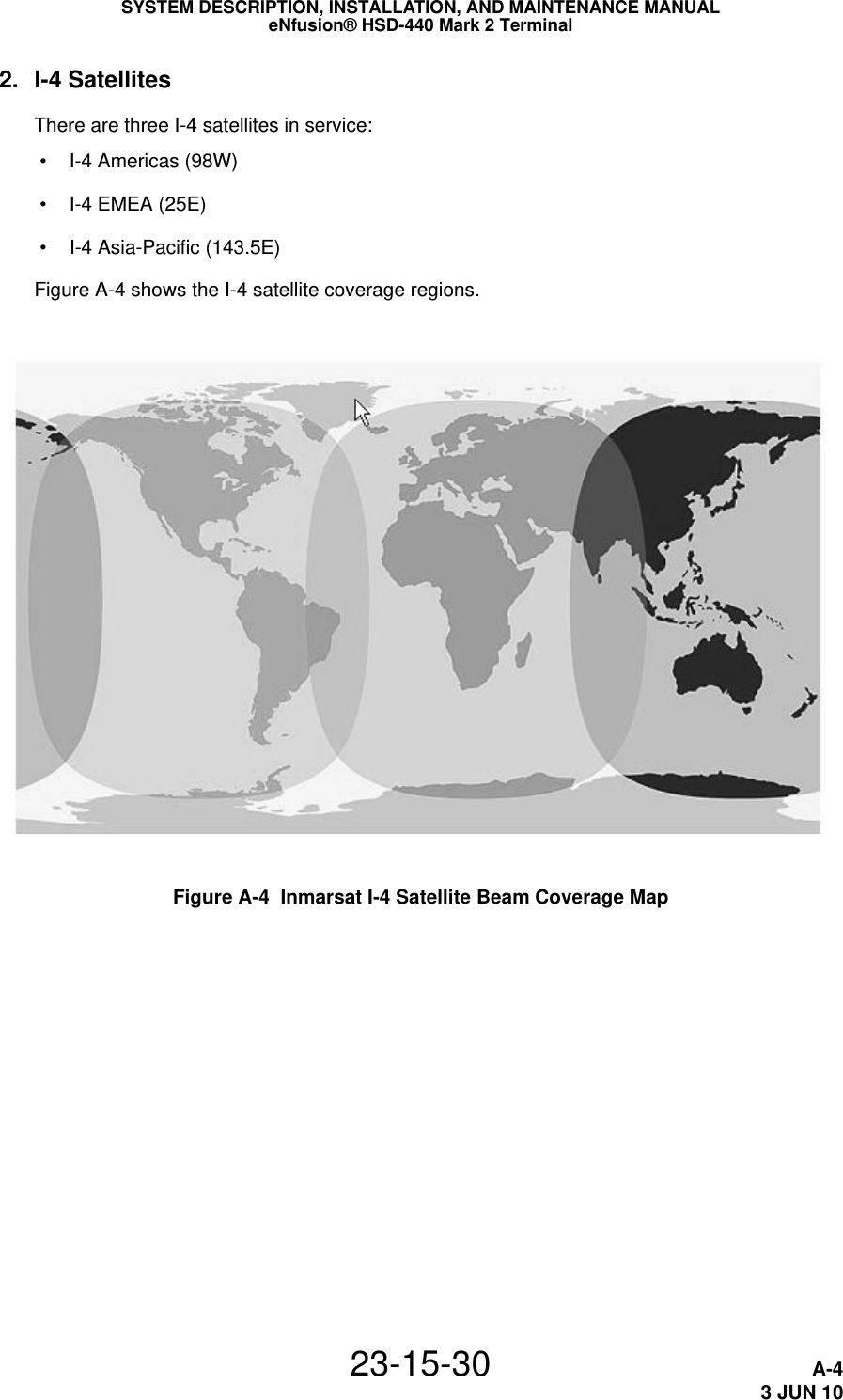
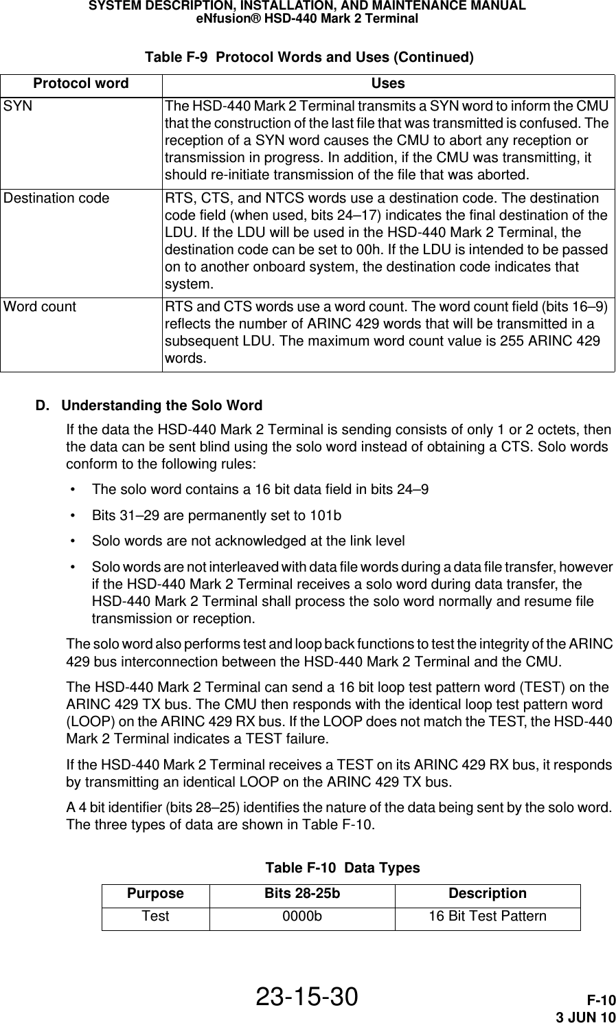
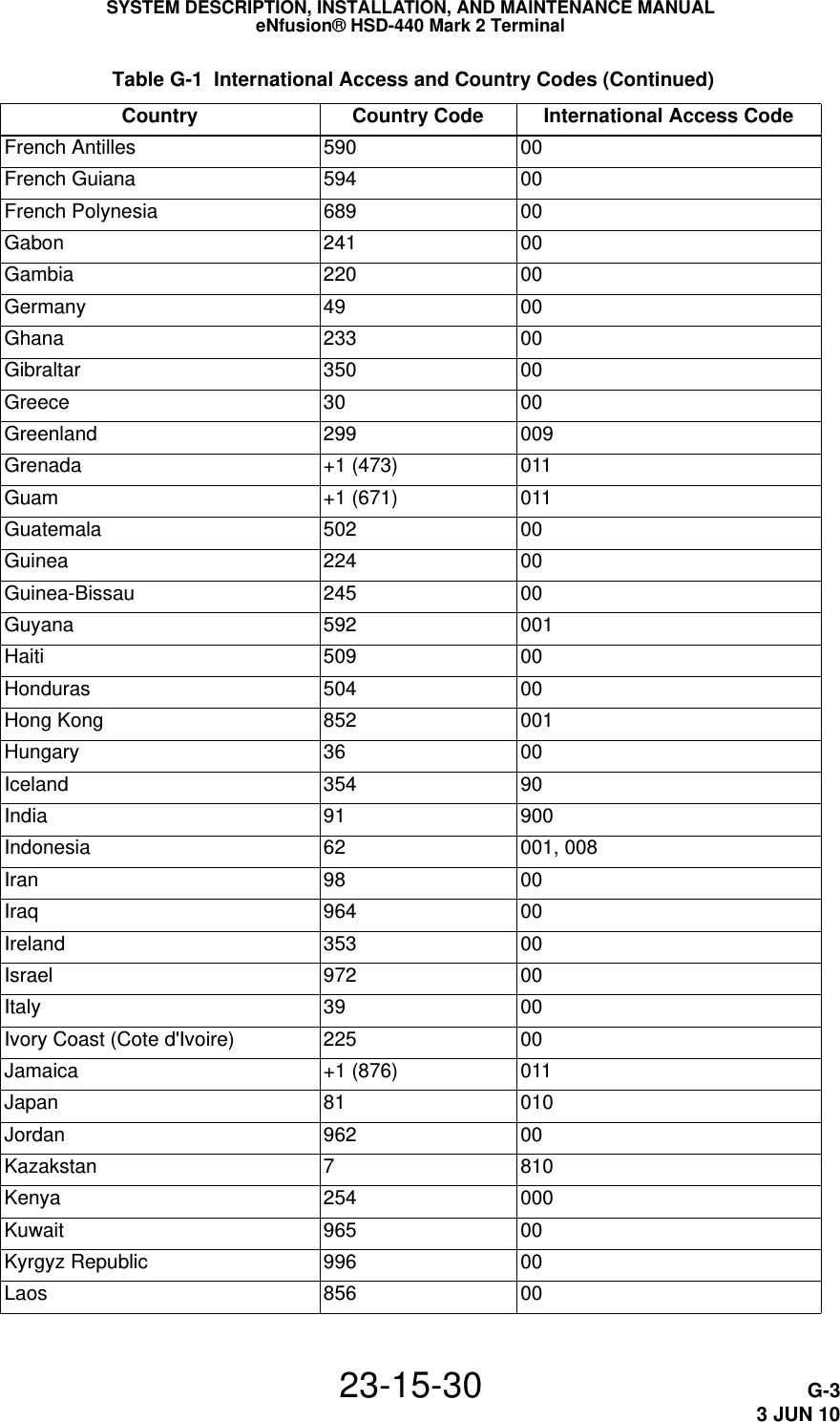
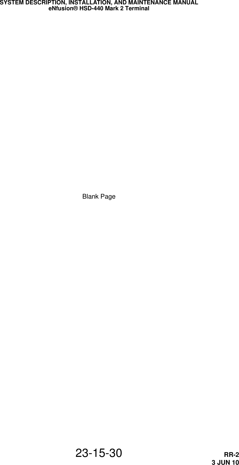
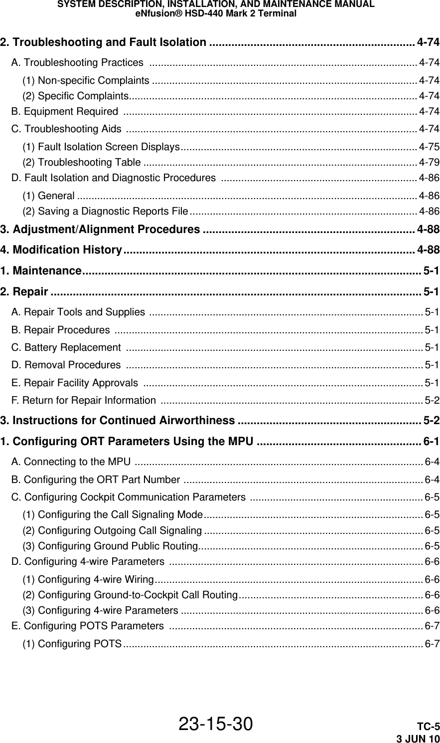
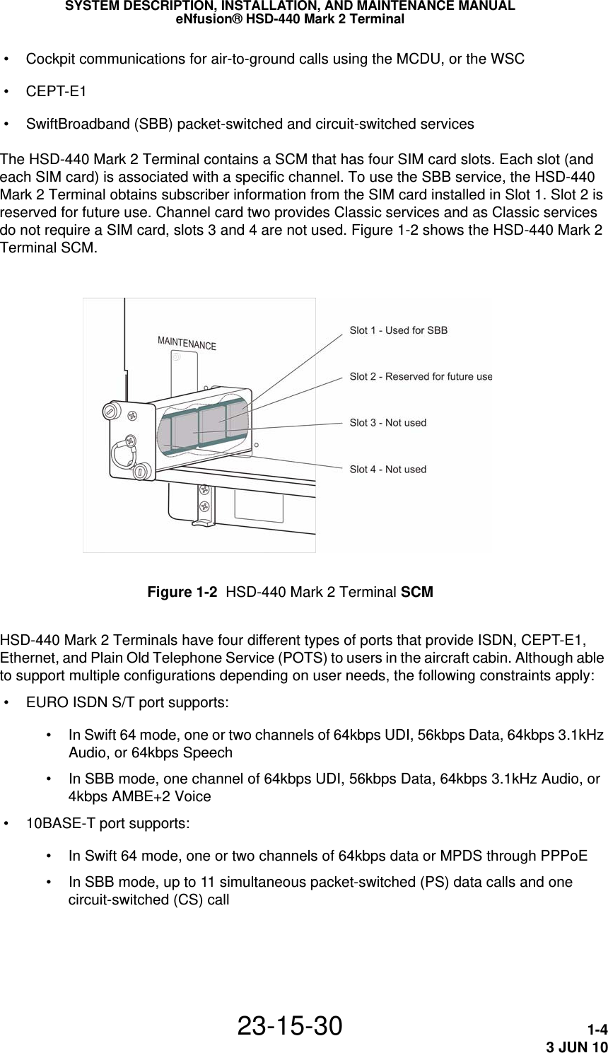
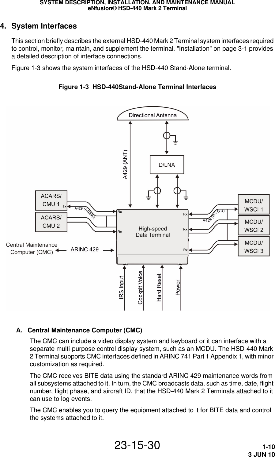
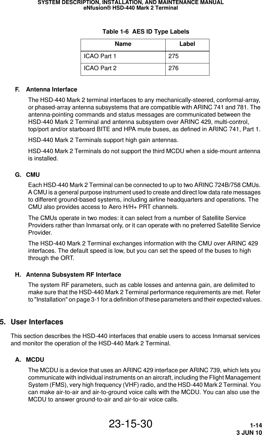
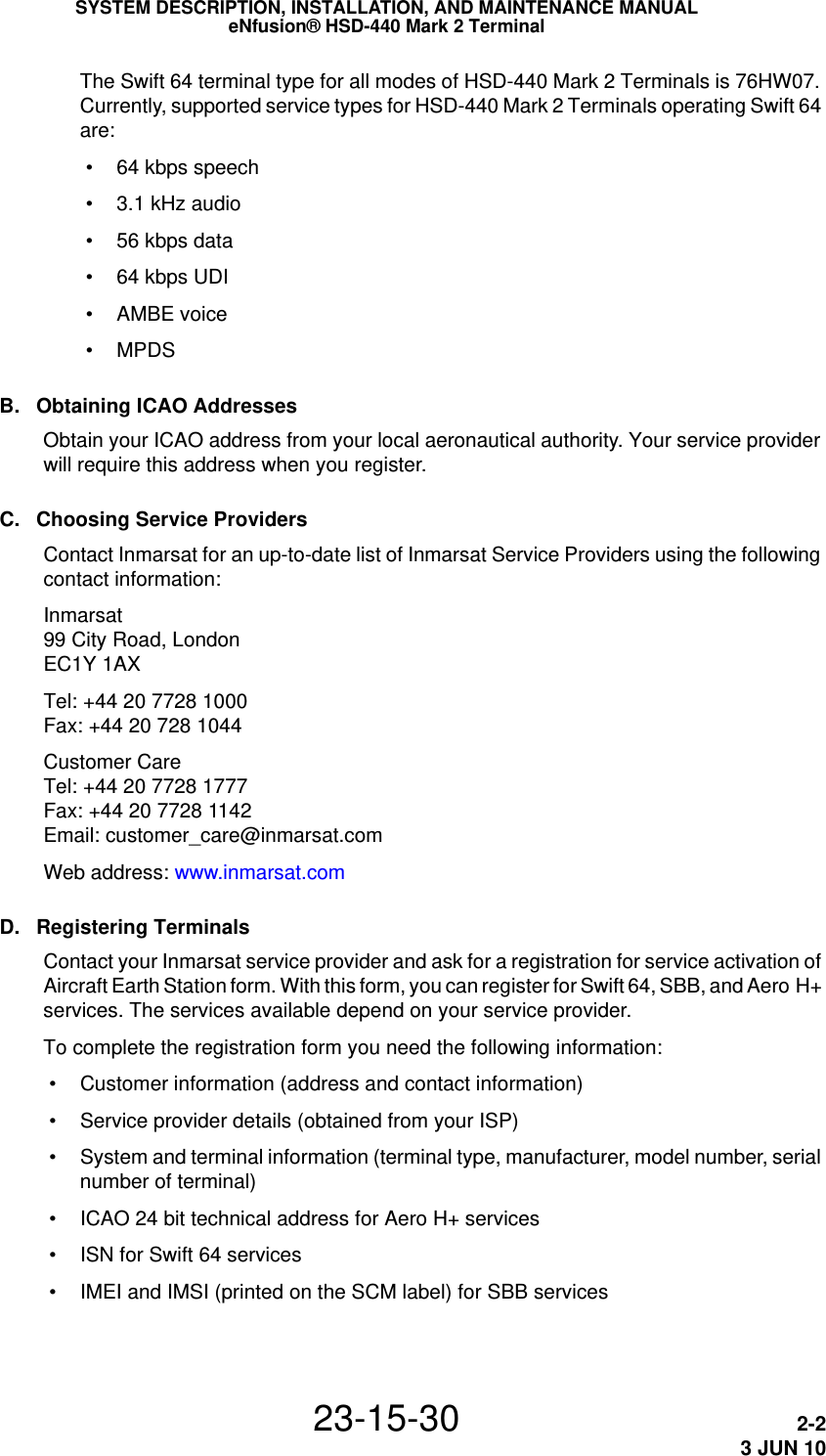
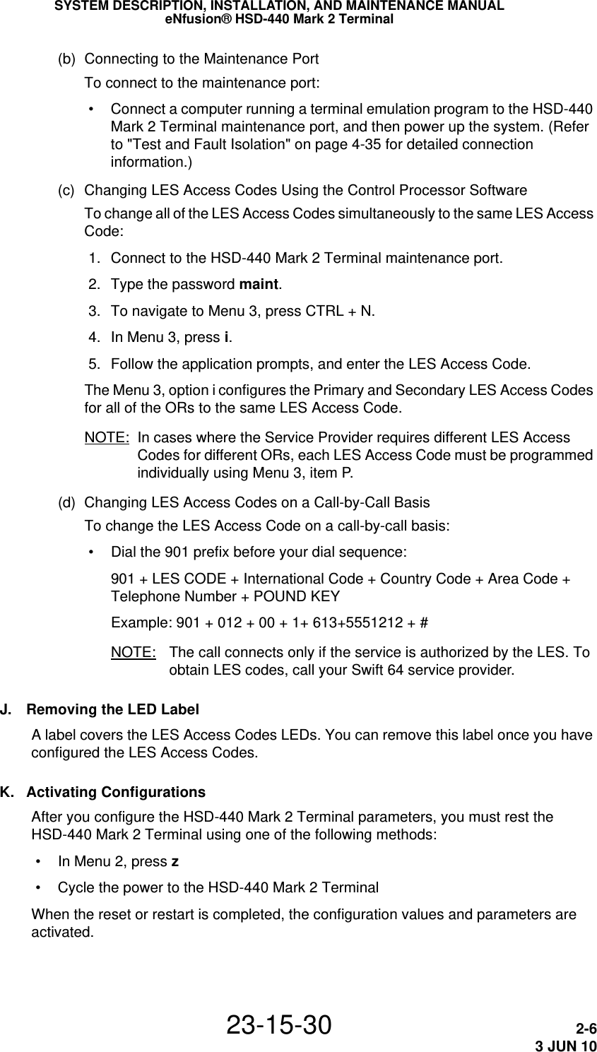
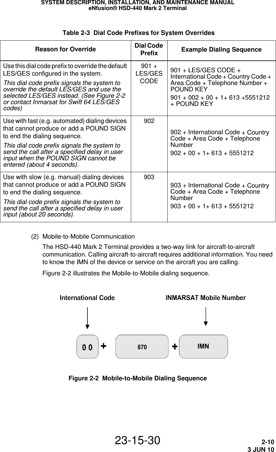
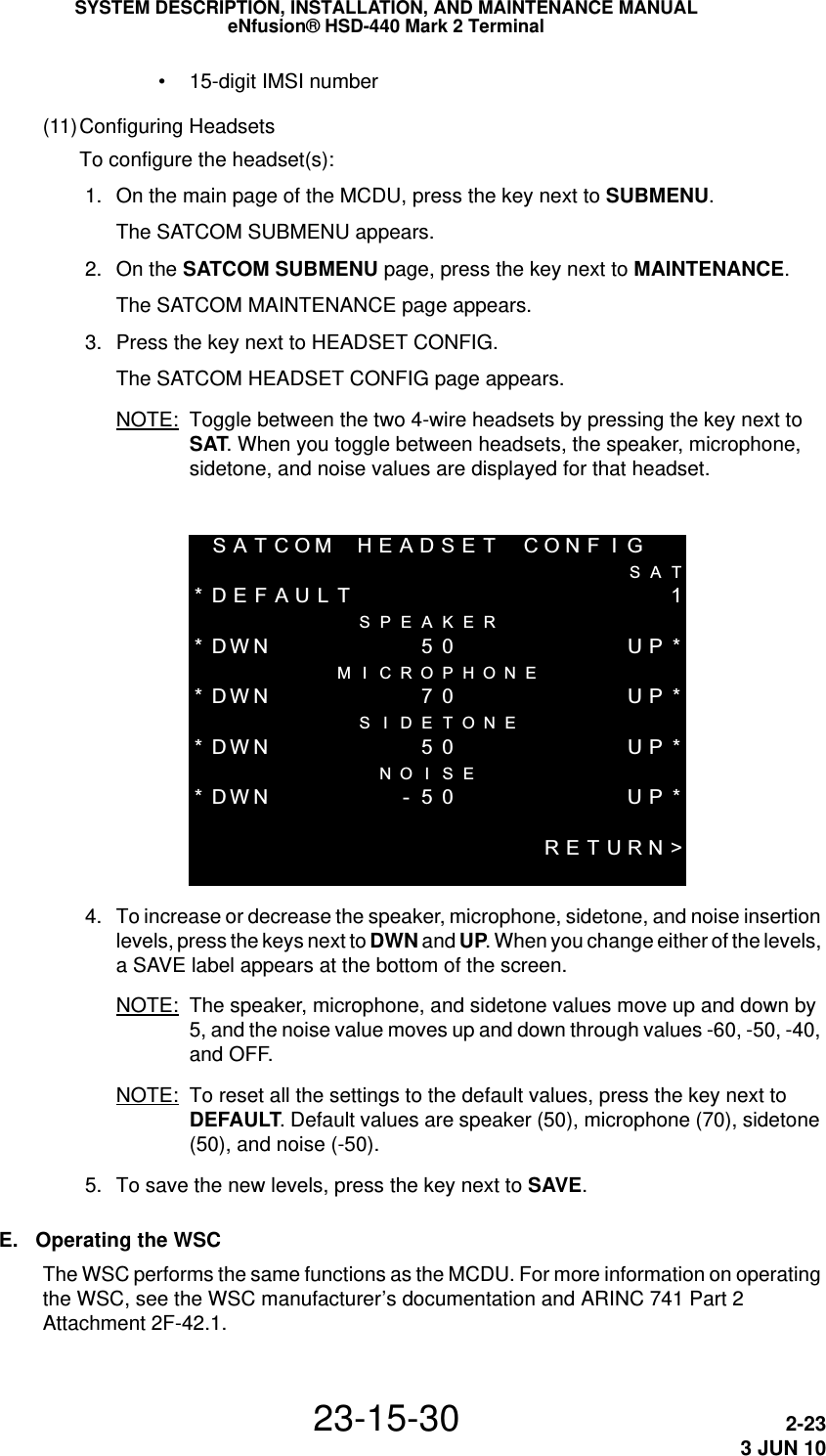
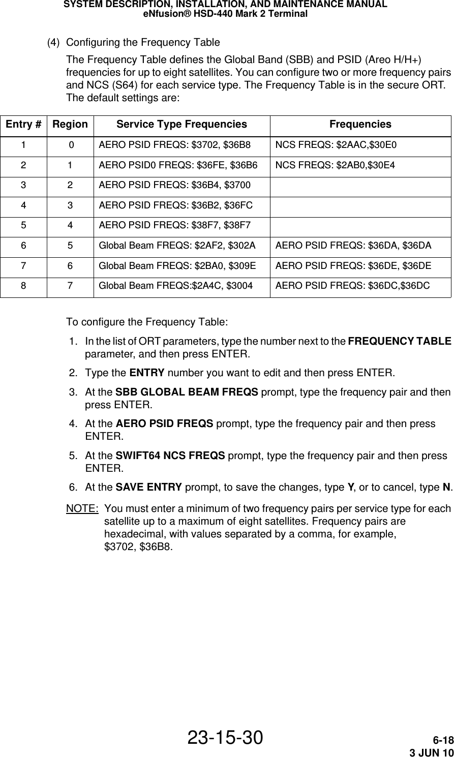
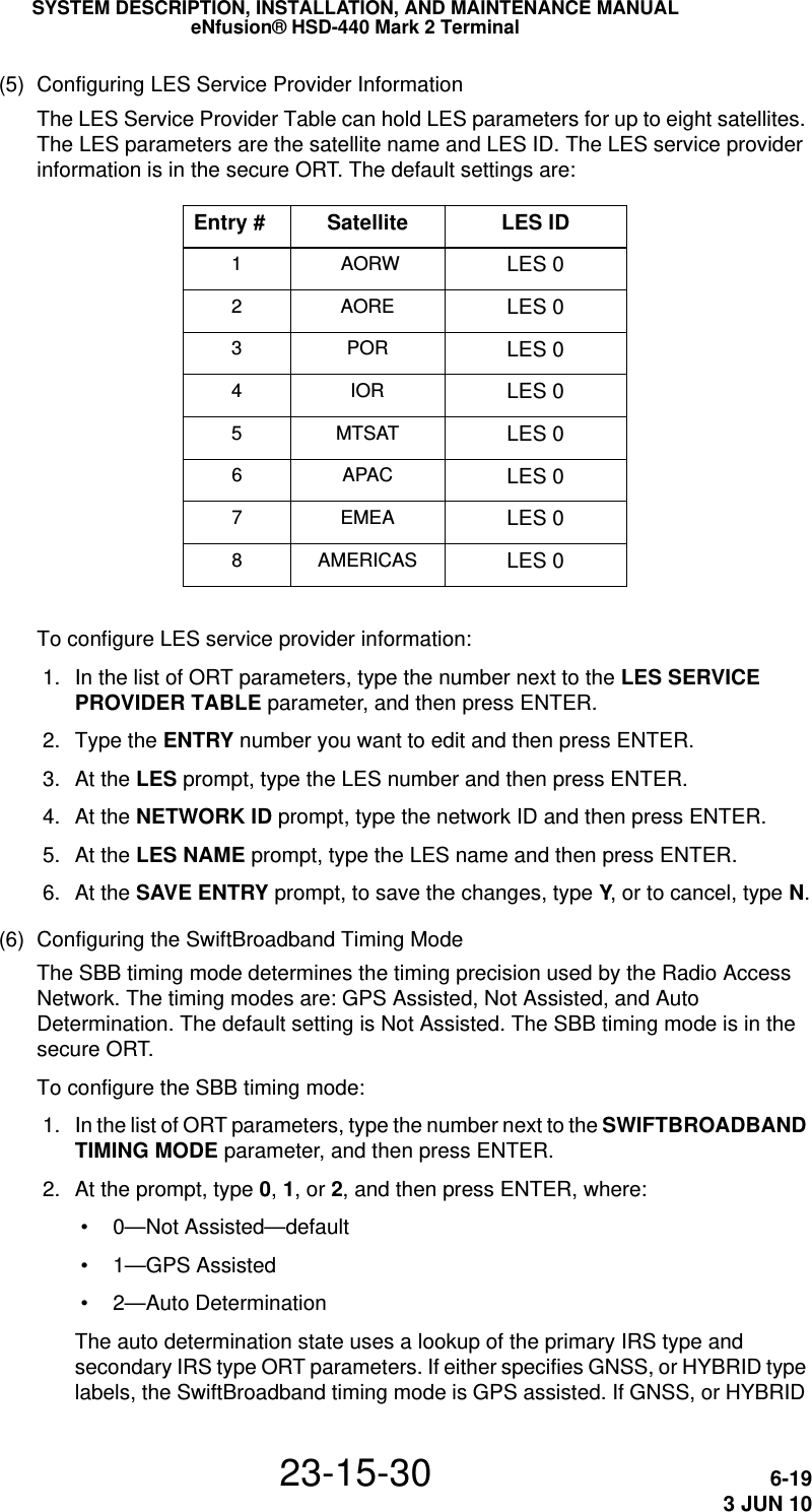
![SYSTEM DESCRIPTION, INSTALLATION, AND MAINTENANCE MANUALeNfusion® HSD-440 Mark 2 Terminal23-15-30 6-163 JUN 10(2) Configuring Satellite InformationYou can configure the name, location, and service available from up to eight satellites. This does not allow access to the satellite network. Satellite information is in the secure ORT. The default settings are:Entry # Region Satellite Name and Longitude Services 1 0 AORW (W) 53.0W CLASSIC AERO, SWIFT642 1 AORE (E) 15.5W CLASSIC AERO, SWIFT643 2 POR (P), 178.0E CLASSIC AERO, SWIFT644 3 IOR (I) 64.0E CLASSIC AERO, SWIFT645 4 MTSAT (4) 142.5E CLASSIC AERO6 5 APAC (5), 144 E CLASSIC AERO, BGAN7 6 EMEA (6), 25.0E CLASSIC AERO, BGAN8 7 AMERICAS (7) 98.0 W CLASSIC AERO, BGANTo configure satellite information: 1. In the list of ORT parameters, type the number next to the SATELLITE NAMES parameter, and then press ENTER. 2. Type the number of the ENTRY you want to modify, and then press ENTER.A prompt appears. For example: EDITING ENTRY #1 REGION 0: NAME [AORW] ? 3. At the NAME prompt, type the satellite name and then press ENTER. 4. At the ABBREVIATION prompt, type an abbreviation for the satellite name and then press ENTER. 5. At the LONGITUDE prompt, type the longitude and then press ENTER. 6. At the SATELLITE SERVICES prompt, identify the service and then press ENTER. You can specify one or more of the following:•Type A for AERO• Type S for SWIFT64•Type B for SBBNOTE: To specify more than one service, for example, classic AERO and Swift 64, type AS. 7. At the SAVE ENTRY prompt, to save the changes, type Y, or to cancel, type N.](https://usermanual.wiki/EMS-Technologies-Canada/HSD-MK2/User-Guide-1306479-Page-188.png)
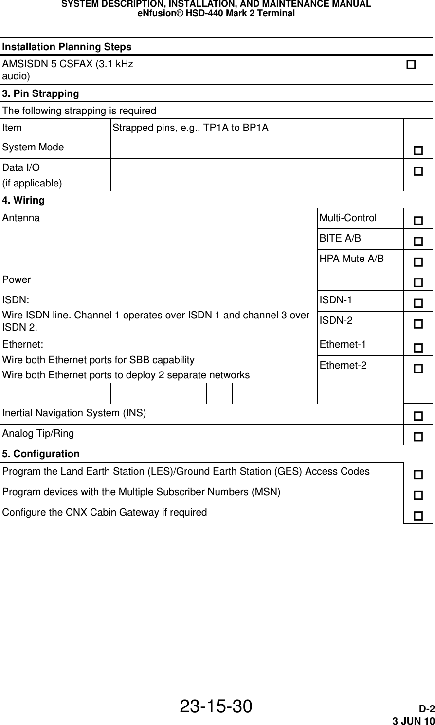
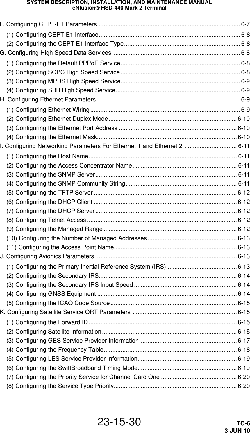
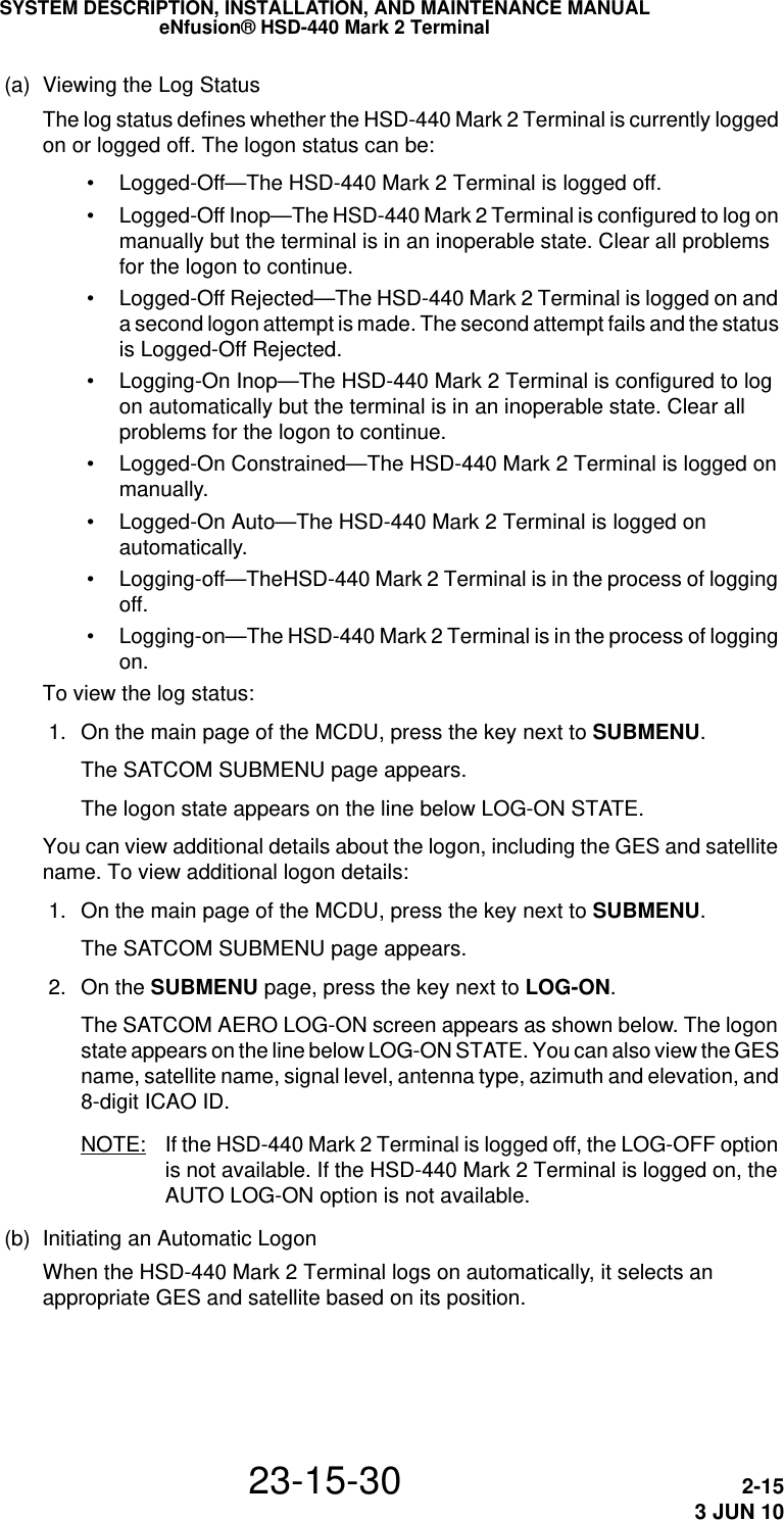
![SYSTEM DESCRIPTION, INSTALLATION, AND MAINTENANCE MANUALeNfusion® HSD-440 Mark 2 Terminal23-15-30 6-173 JUN 10(3) Configuring GES Service Provider InformationYou can configure the GES Name, satellite ID, GES ID, and priority for up to 33 GESs. GES information is in the secure ORT. Note the GES ID in the following table is an Octal number. The default settings are:GES Name Satellite ID GES ID PriorityAussaguel 005 5Eik 002 5Aussaguel 1103 5Eik 1104 5Perth 2205 5Santa Paula 2202 5Perth 3305 5Eik 3301 5Hawaii 5120 5Fucino 6220 5Hawaii 7320 5To configure GES service provider information: 1. In the list of ORT parameters, type the number next to the GES SERVICE PROVIDER TABLE parameter, and then press ENTER.A prompt appears. For example: OTHER ENTRIES ARE EMPTY -- ENTER NUMBER OF ENTRY TO EDIT (1,33) ? 2. At the ENTRY prompt, type the entry number to add or edit and then press ENTER. 3. At the SATELLITE prompt, type the number of the satellite ID and then press ENTER. 4. At the GES [octal]? prompt, type the number (in Octal) of the GES ID and then press ENTER. 5. At the PRIORITY prompt, type a number between 1 and 10 and then press ENTER. 6. At the GES NAME prompt, type in the GES name and then press ENTER. 7. At the SAVE ENTRY prompt, to save the changes, type Y, or to cancel, type N.](https://usermanual.wiki/EMS-Technologies-Canada/HSD-MK2/User-Guide-1306479-Page-189.png)
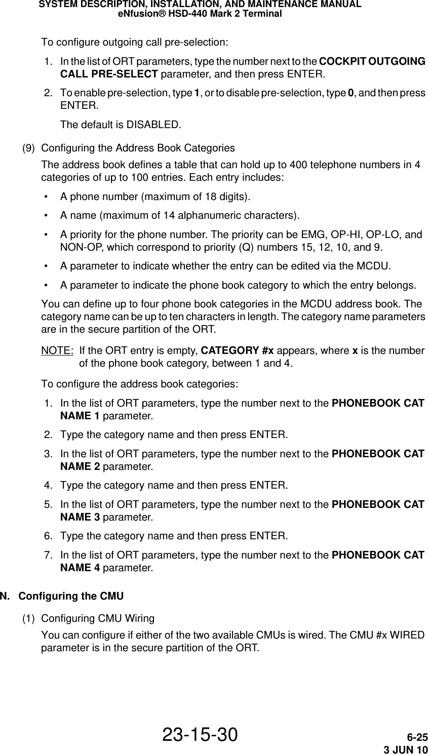
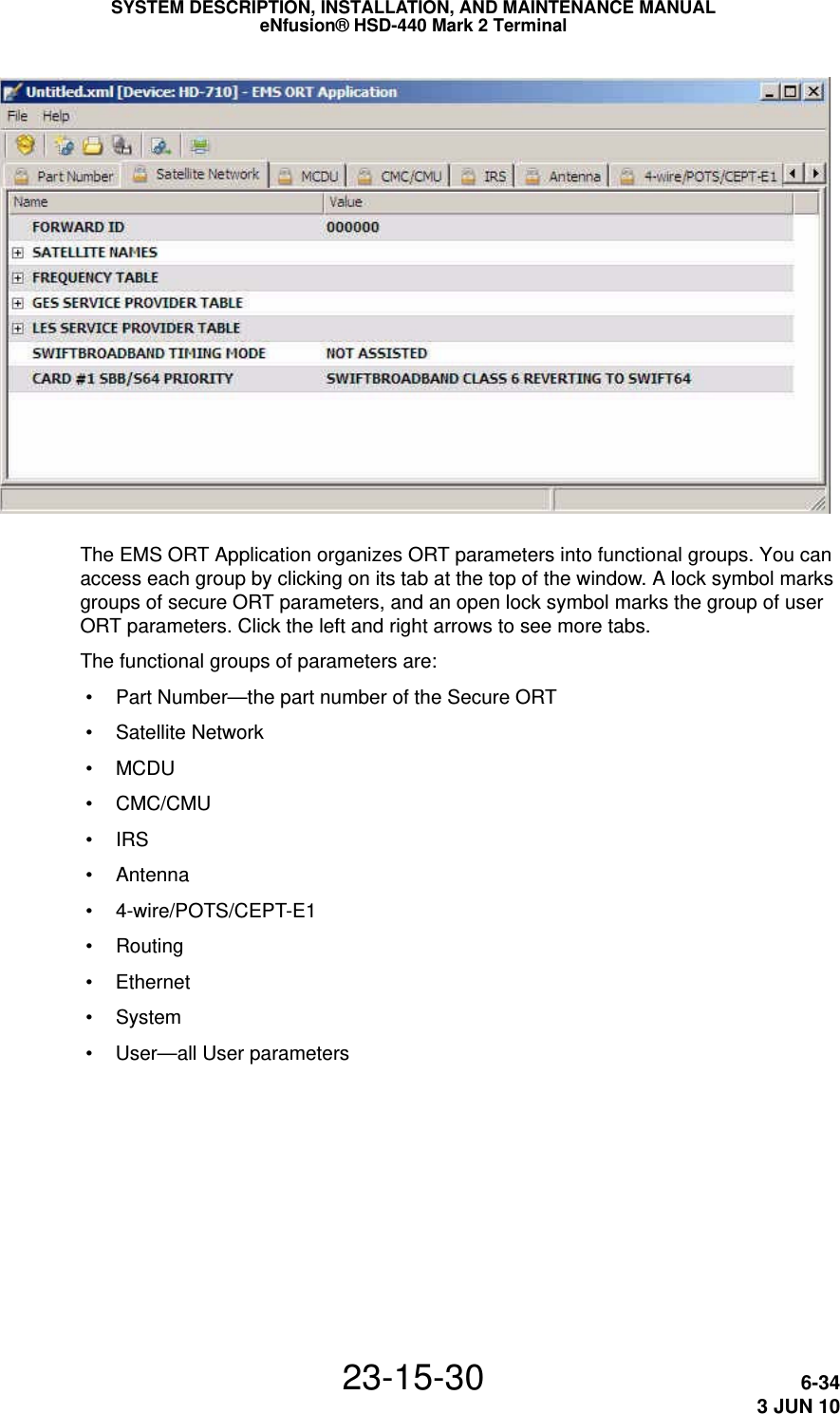
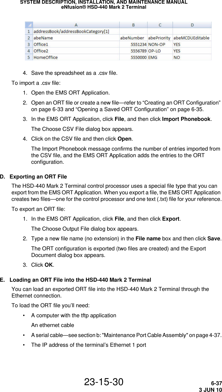
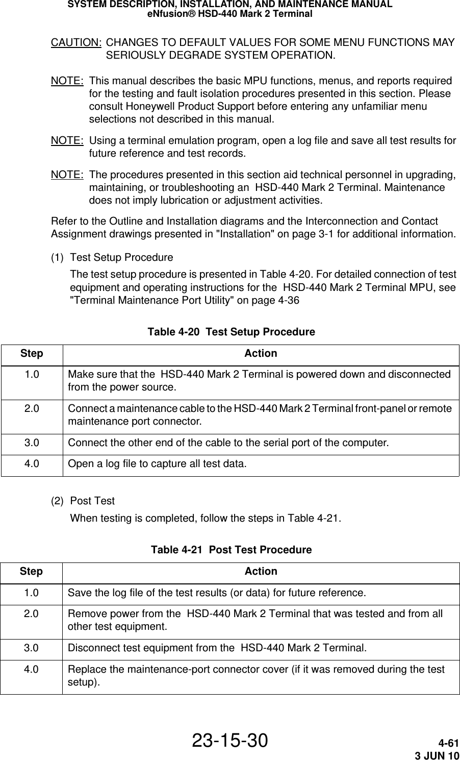
![SYSTEM DESCRIPTION, INSTALLATION, AND MAINTENANCE MANUALeNfusion® HSD-440 Mark 2 Terminal23-15-30 6-363 JUN 10The ORT Address book parameter includes four categories with 100 entries in each category. You can create and import a separate file for each category. The EMS ORT Application creates address book entries from imported Comma Separated Value (CSV) files that have the .csv file extension. You can create .csv files with Microsoft® Excel®.Importing a phone book includes: • Creating a .csv file • Importing the .csv file into the EMS ORT ApplicationTo create a .csv file: 1. Open Microsoft Excel. 2. Type the following into the specified cells, as shown below: • cell A1—addressBook/addressBookCategory[1] • The EMS ORT Application adds the entries in this file into Category 1 of the Address book. • To create categories two, three, and four, change the category number inside the square brackets. You need to create a separate .csv file for each category. • cell A2—abeName • cell B2—abeNumber • cell C2—abePriority • cell D2—abeMCDUEditable 3. For each entry you want to add to the address book, type data in the columns abeName, abeNumber, abePriority, and abeMCDUEditable. Each row represents one address book entry: • In column abeName, type the name of the address book entry. The maximum length of the name is 14 alphanumeric characters. • In column abeNumber, type the phone number without hyphens or spaces. The maximum length of the phone number is 18 digits. • In the column abePriority, type the priority of this entry. Priority may be one of OP-HI, OP-LO, NON-OP, or EMG. • In the abeMDCUEditable column, type YES or NO to indicate if this entry is editable from the MCDU.](https://usermanual.wiki/EMS-Technologies-Canada/HSD-MK2/User-Guide-1306479-Page-208.png)