EMS Technologies Canada HSD-X eNfusion HSD-X Aeronautical Satcom Terminal User Manual MN 1110 10113
EMS Technologies Canada, Ltd. eNfusion HSD-X Aeronautical Satcom Terminal MN 1110 10113
UserManual.wiki
>
EMS Technologies Canada
>
HSD X User Manual
HSD-X User Manual
Navigation menu
Upload a User Manual
Namespaces
Wiki Guide
HTML
PDF
Info
Views
User Manual
Discussion / Help
Navigation


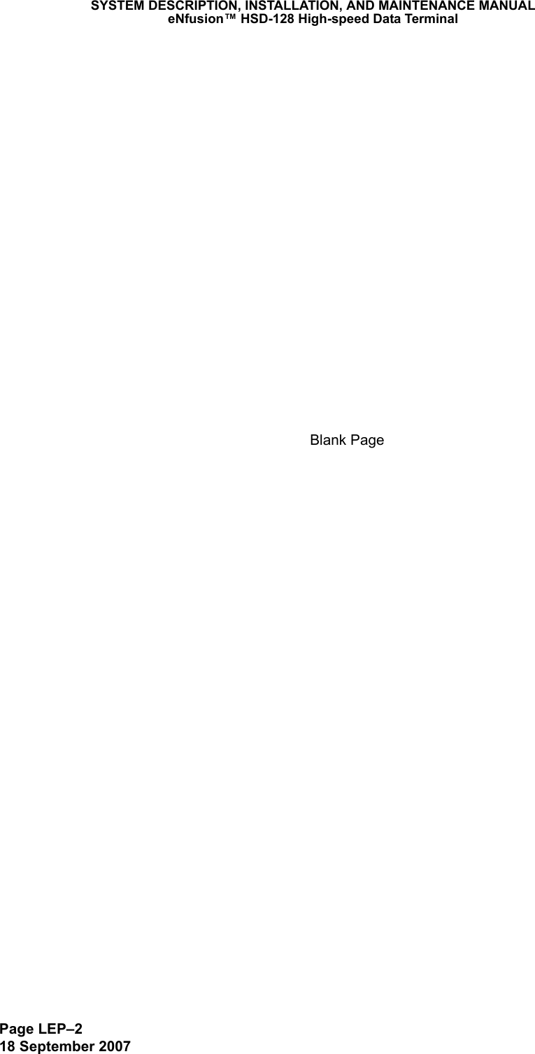
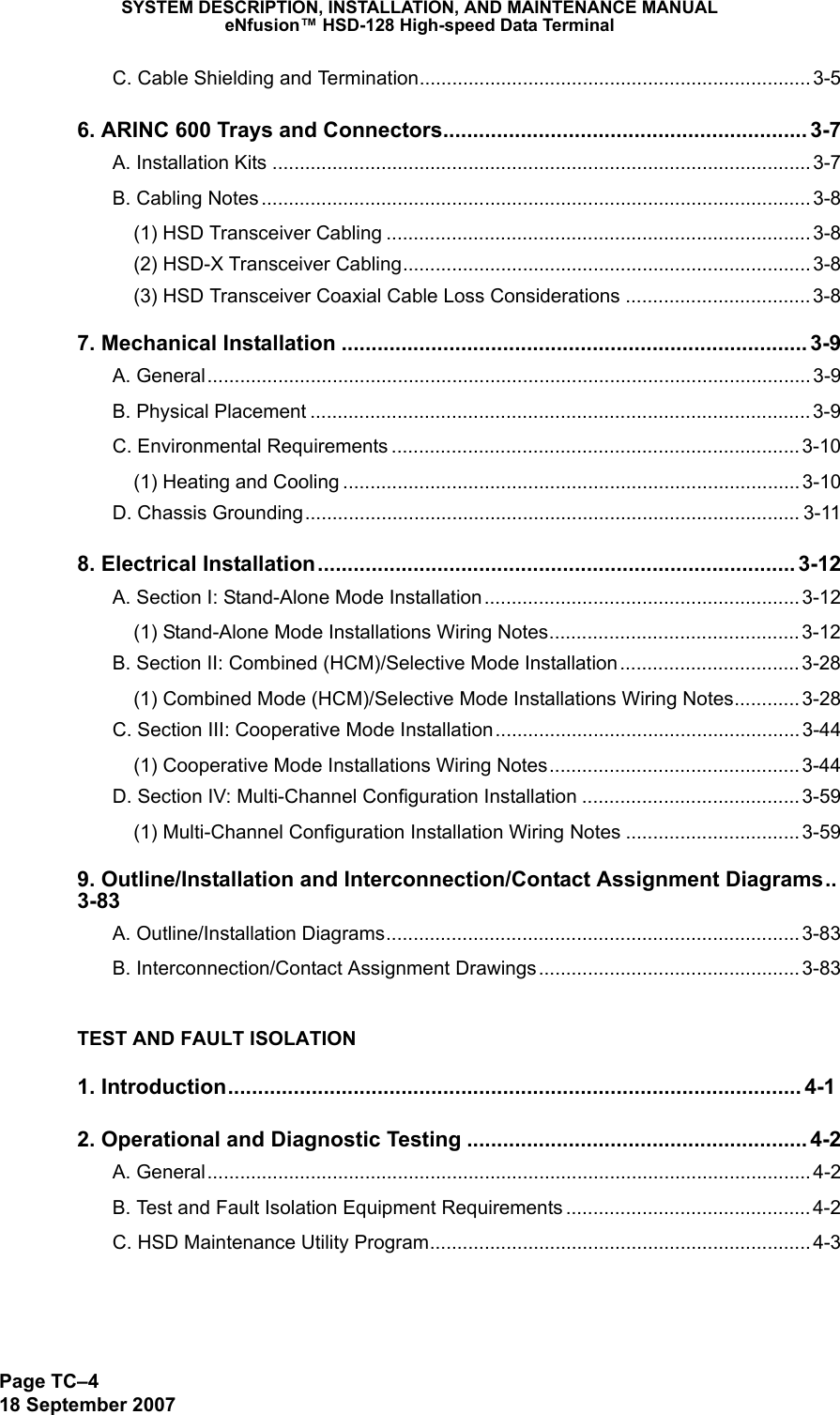
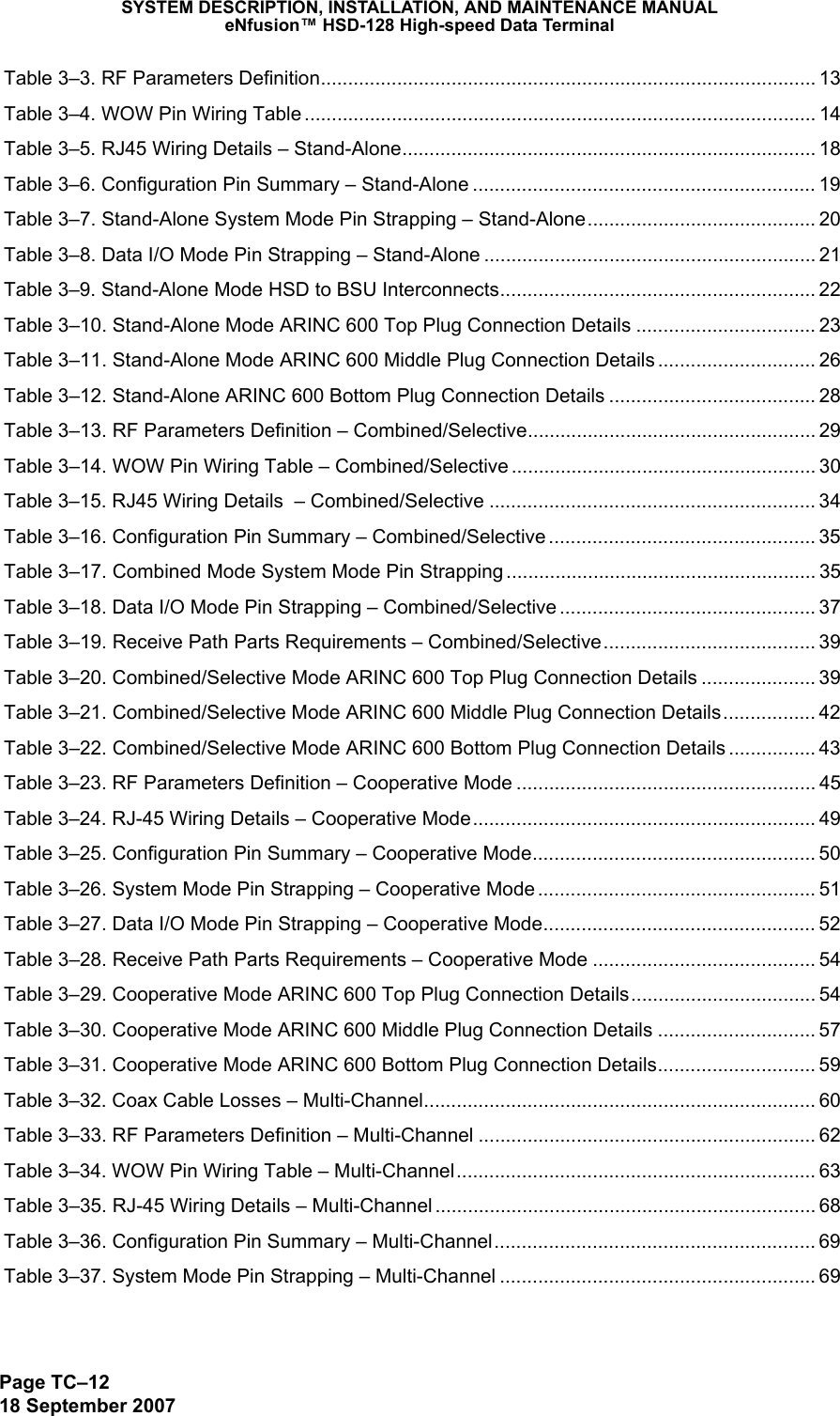

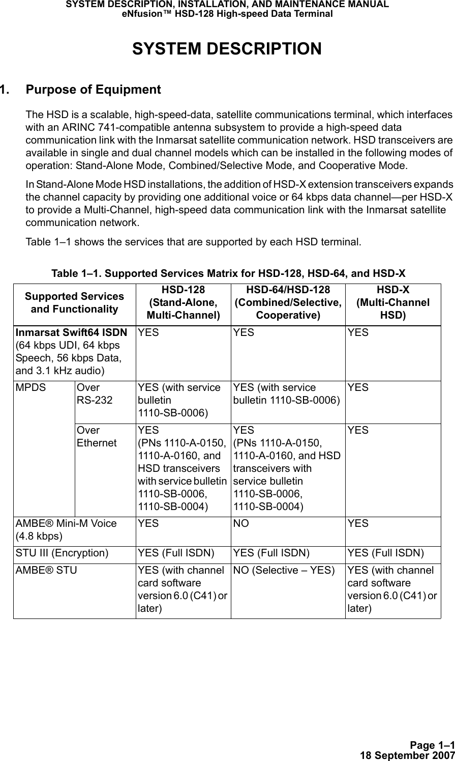
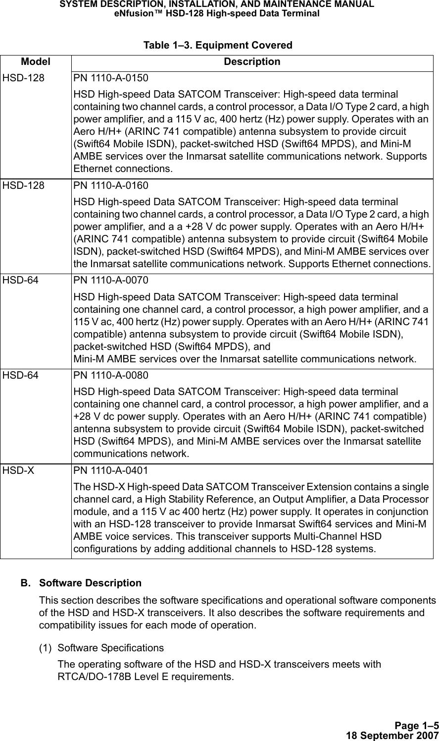
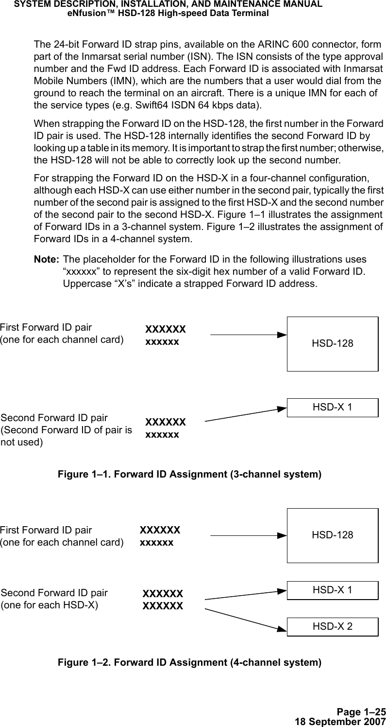
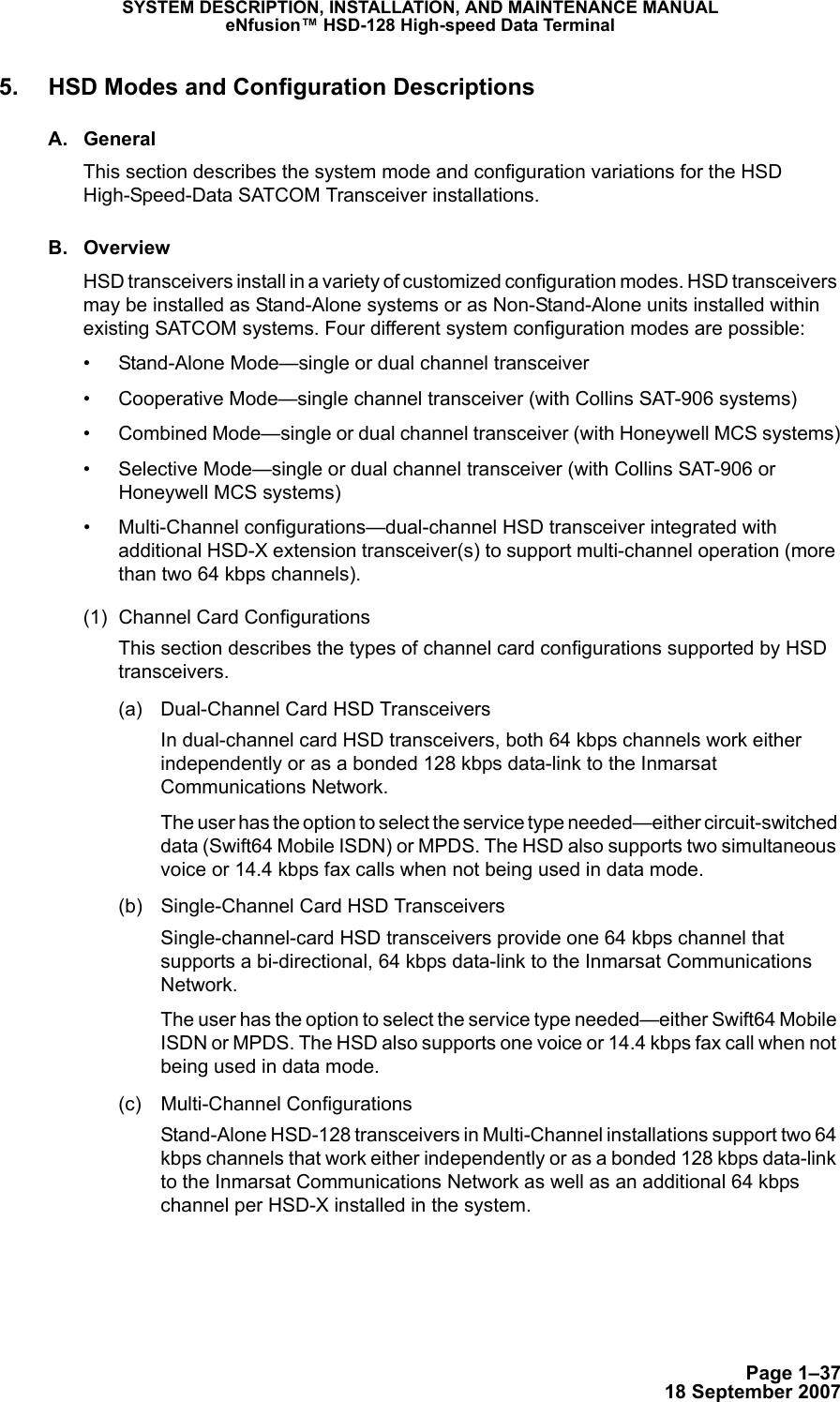
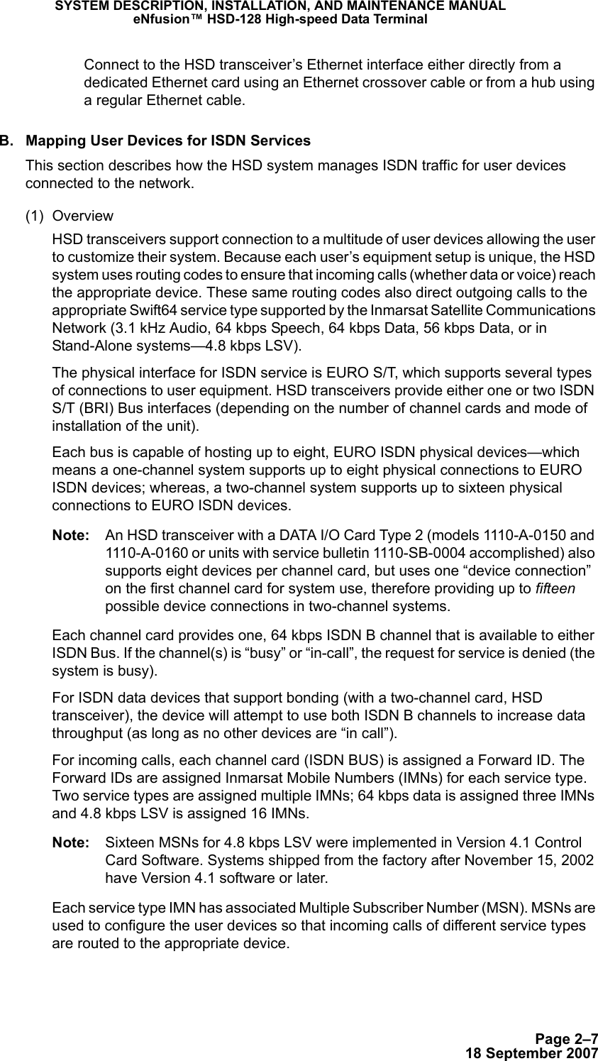
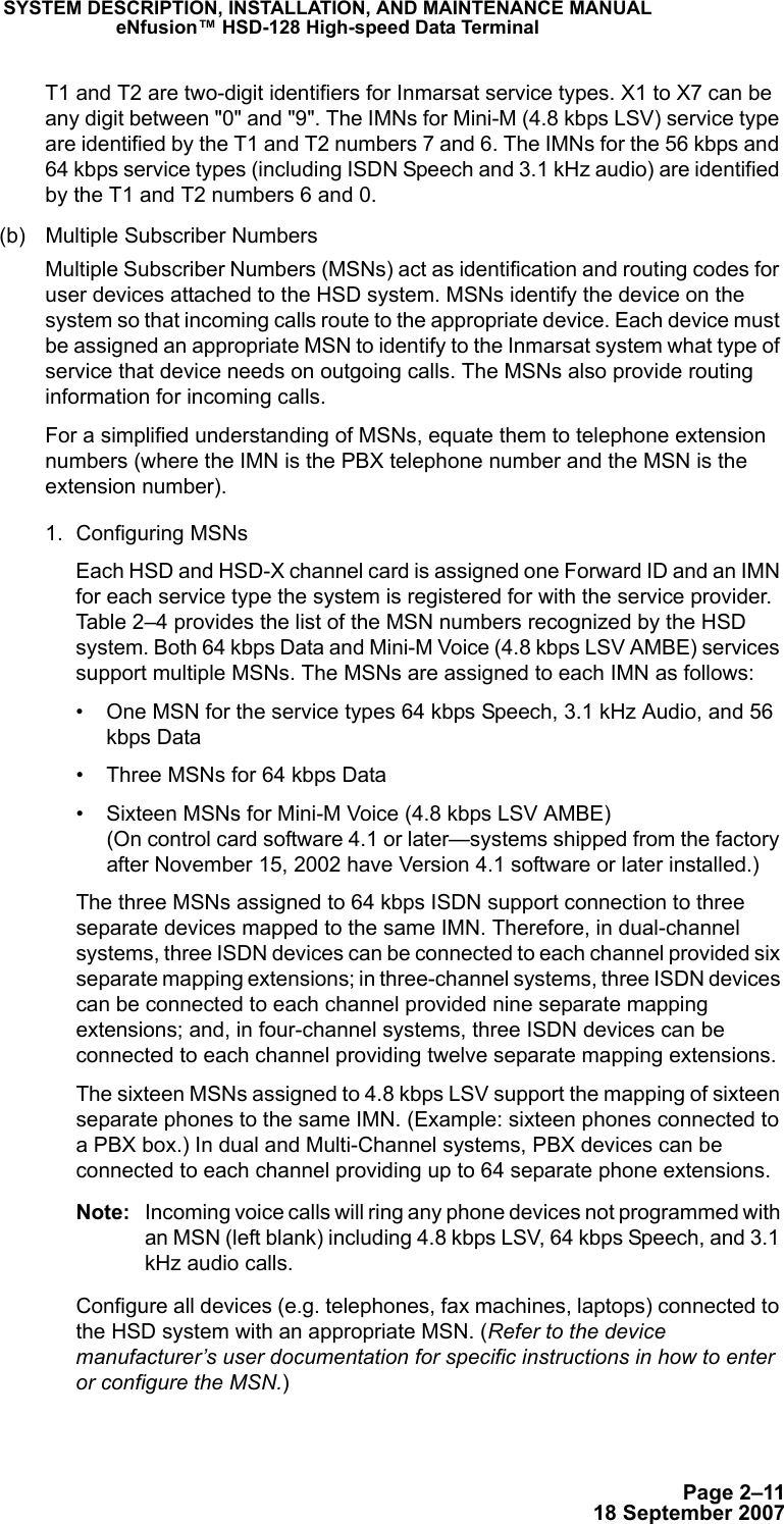
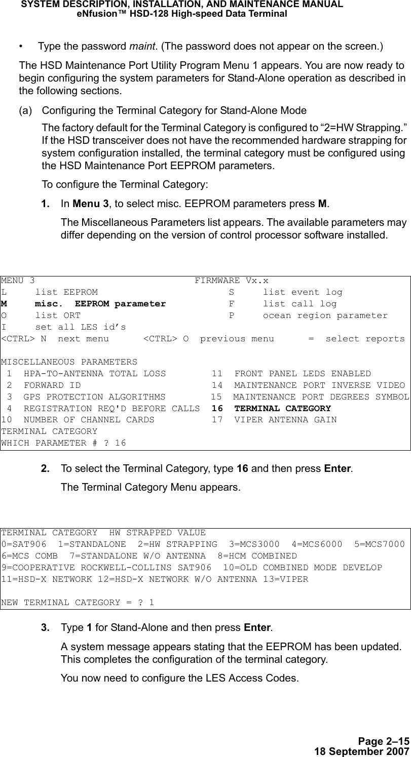
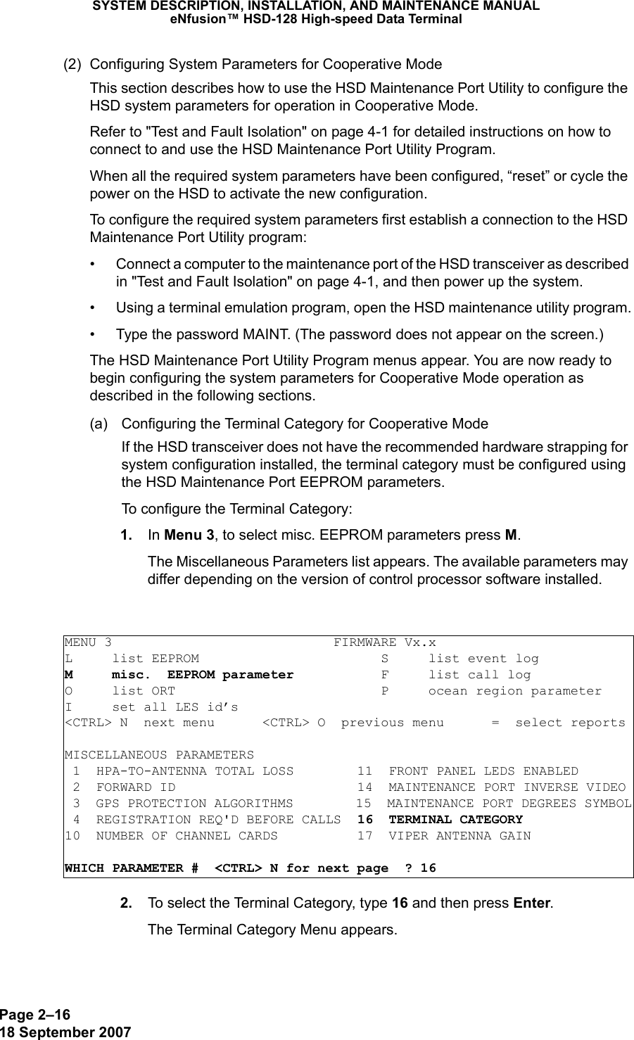
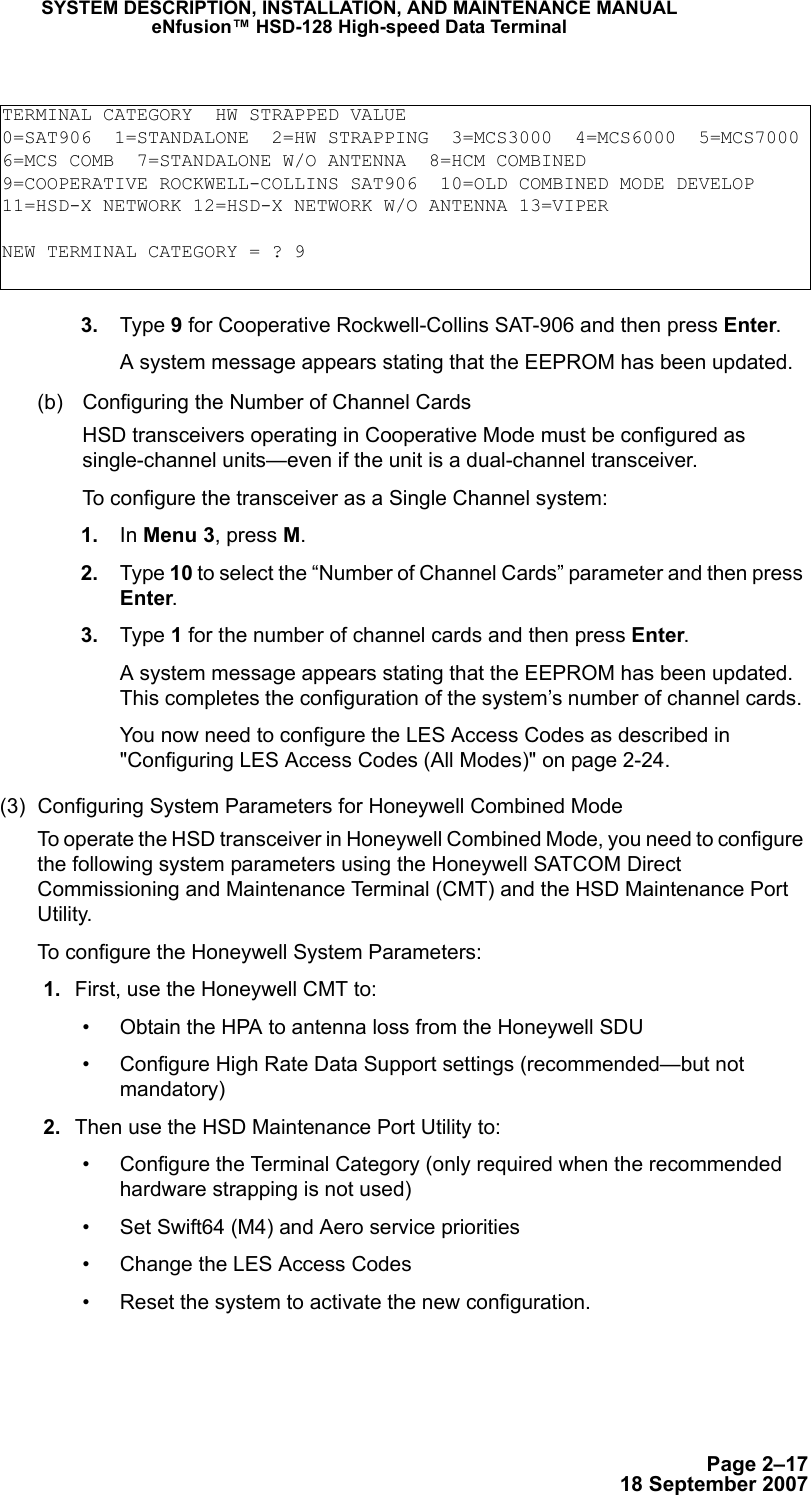
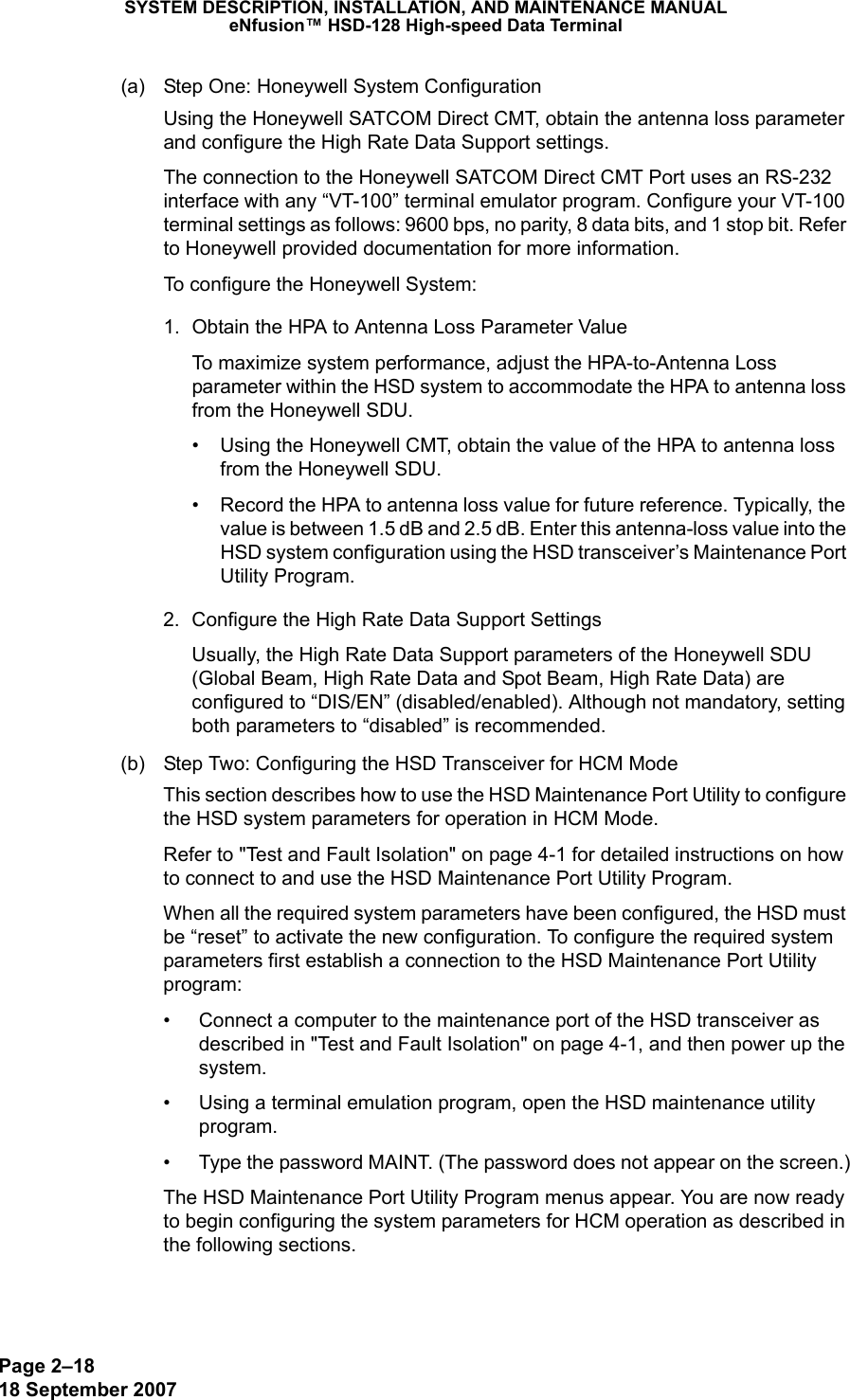
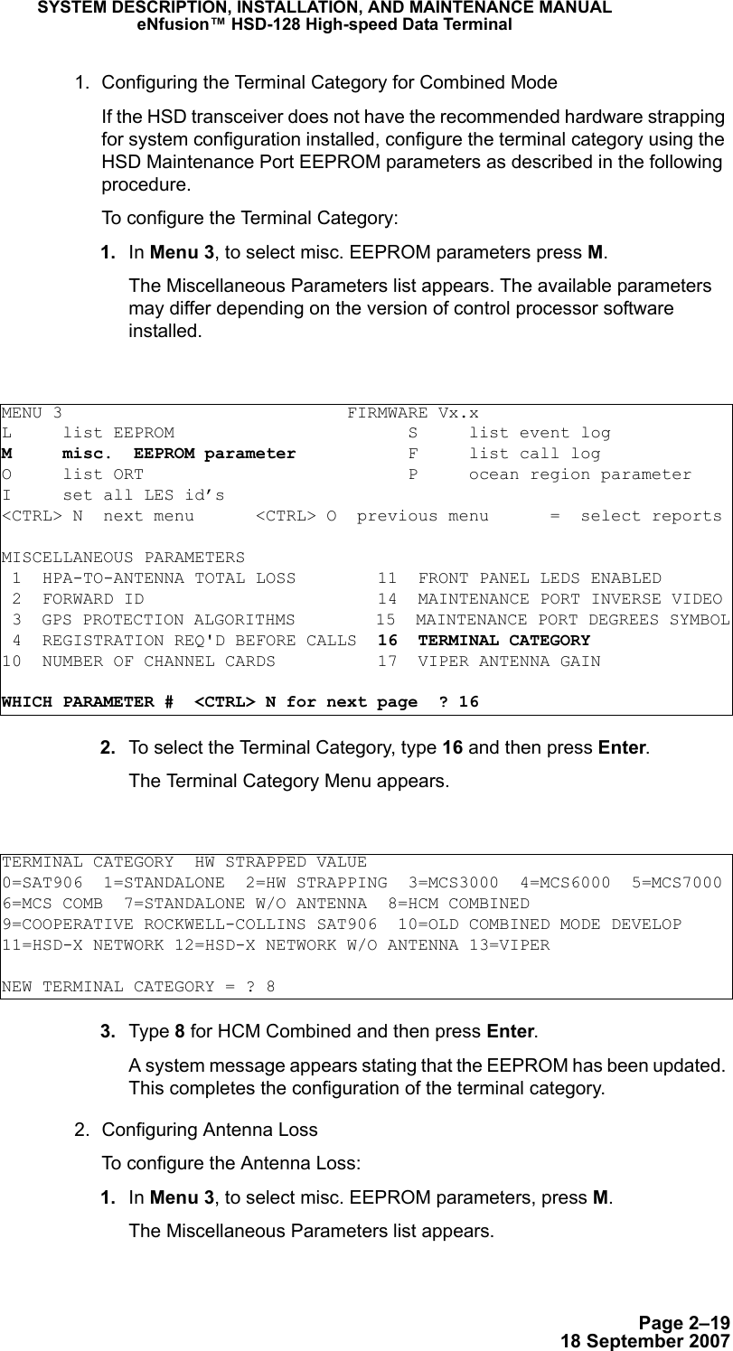
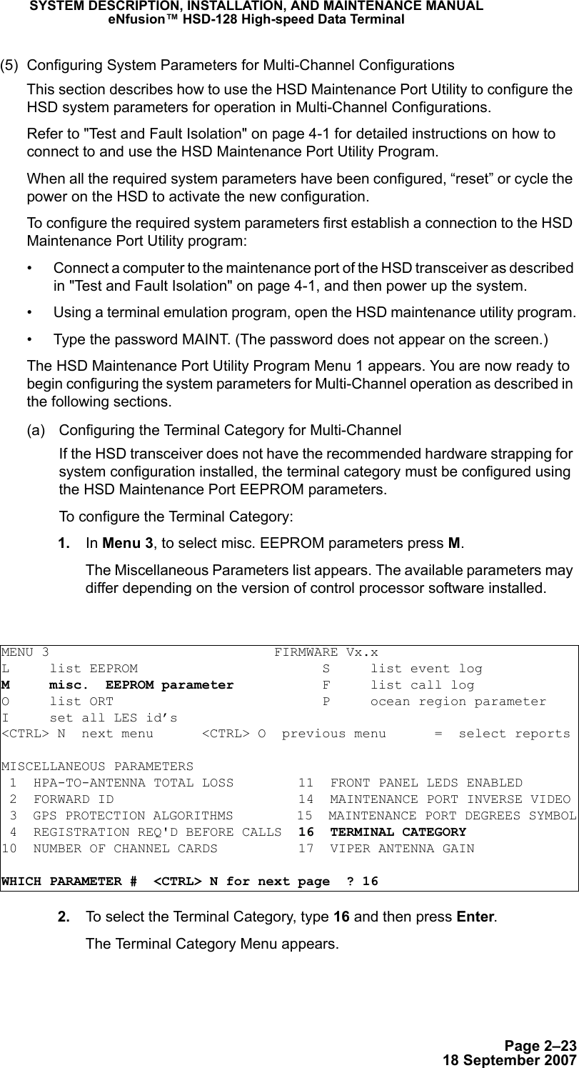
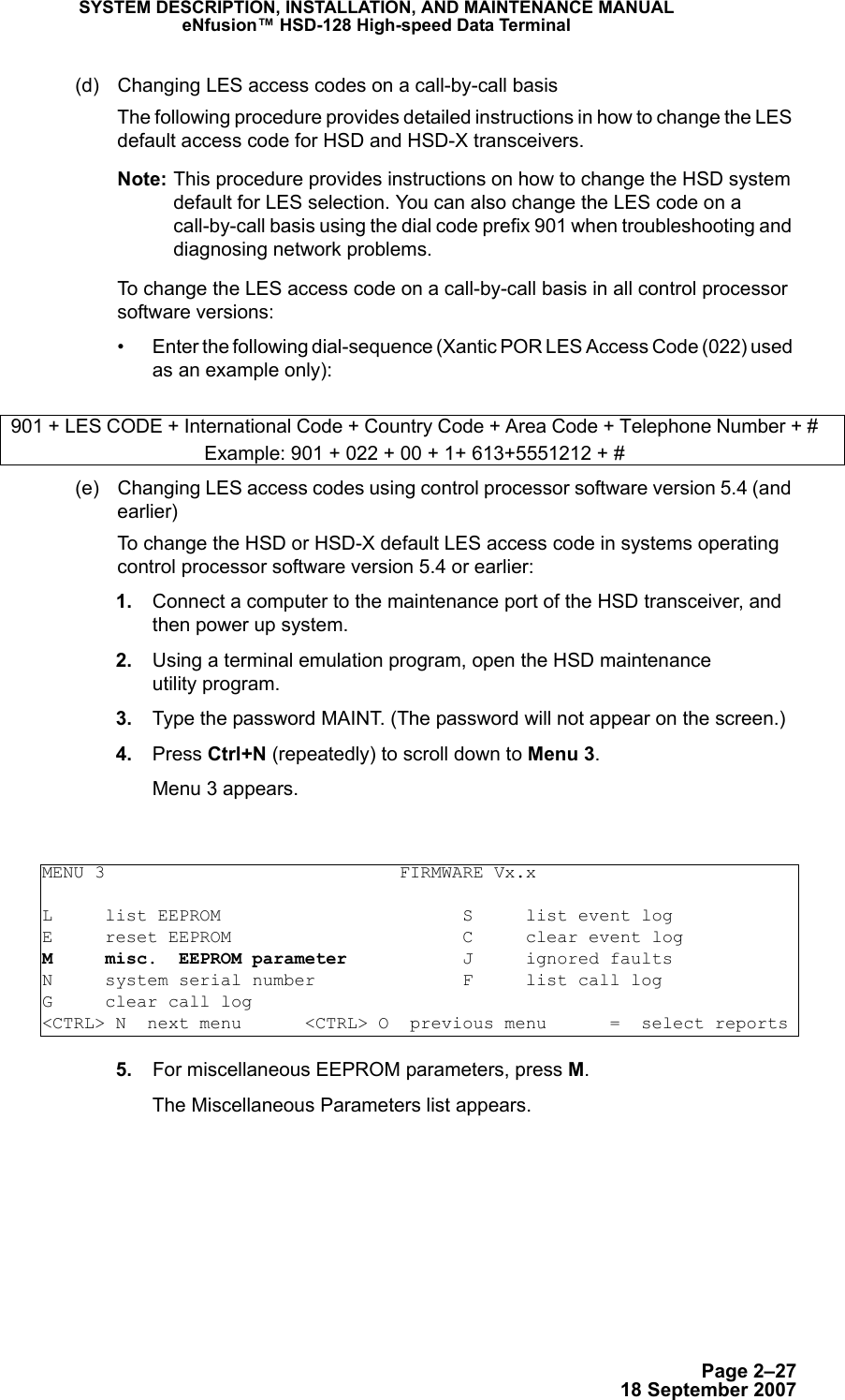
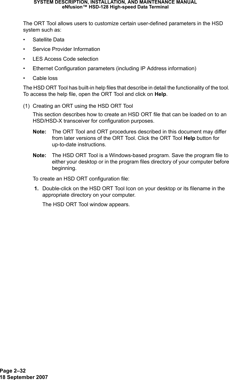
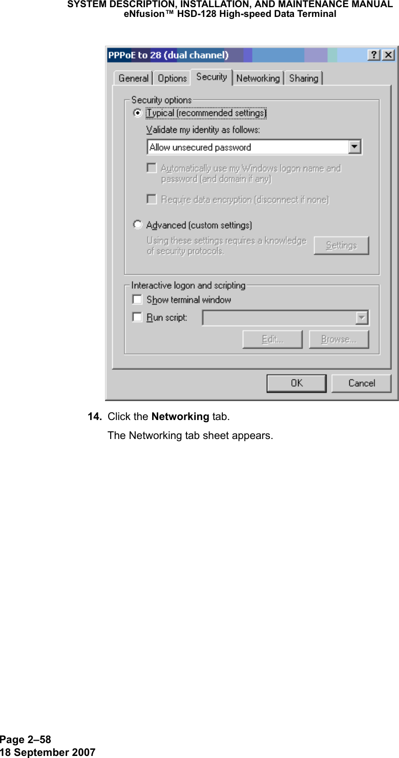
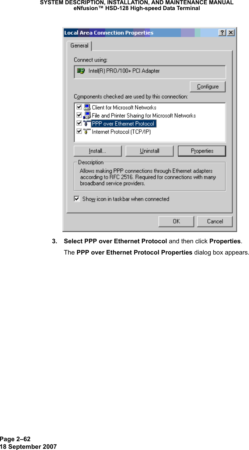
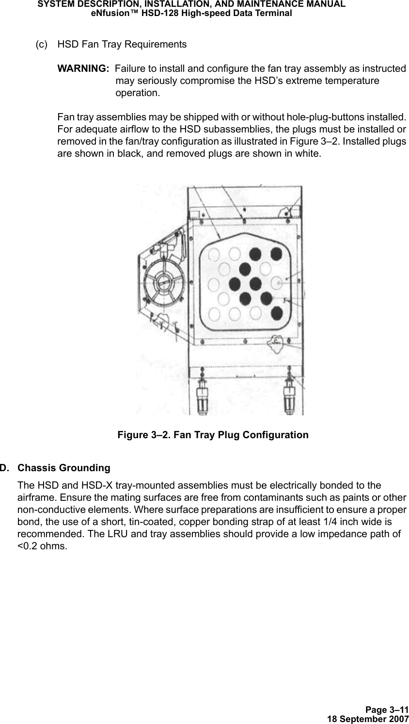
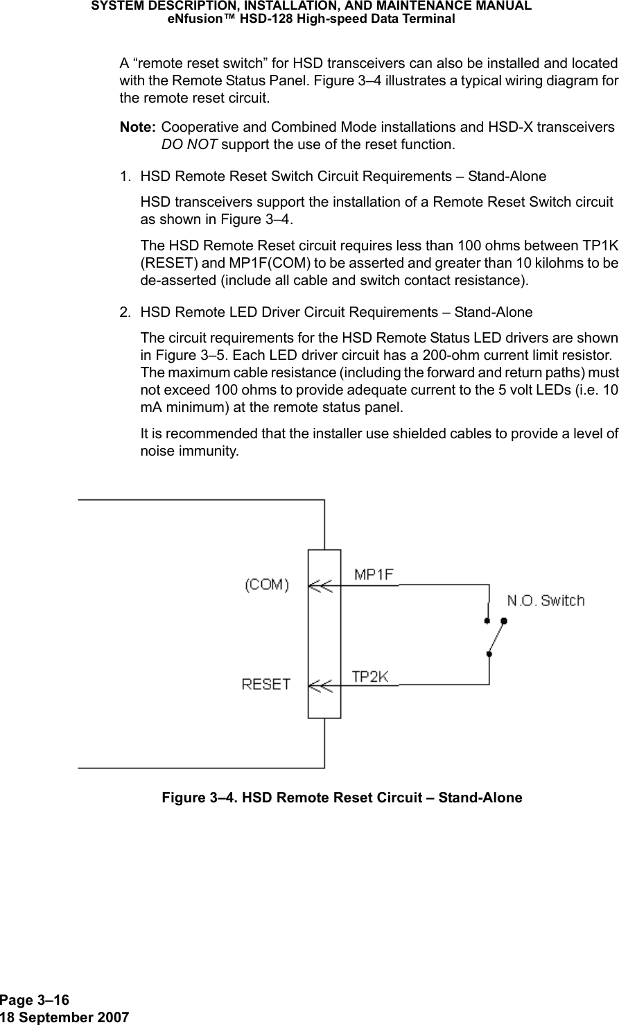
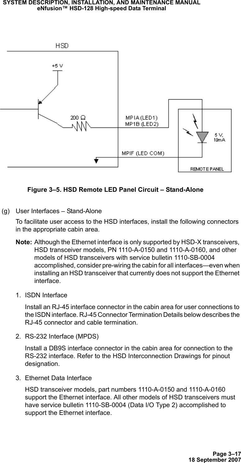
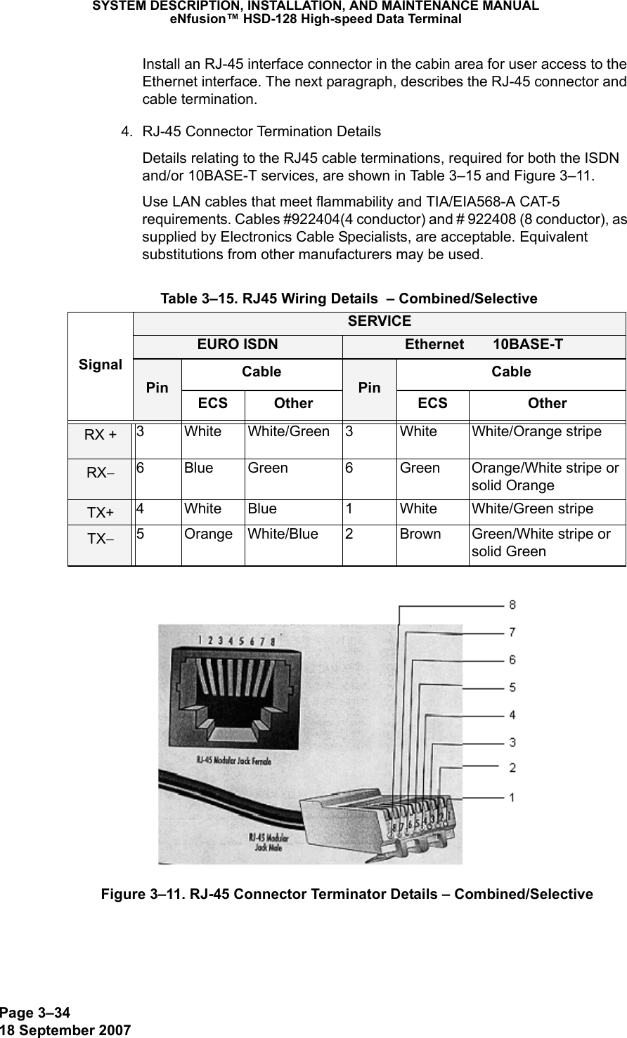
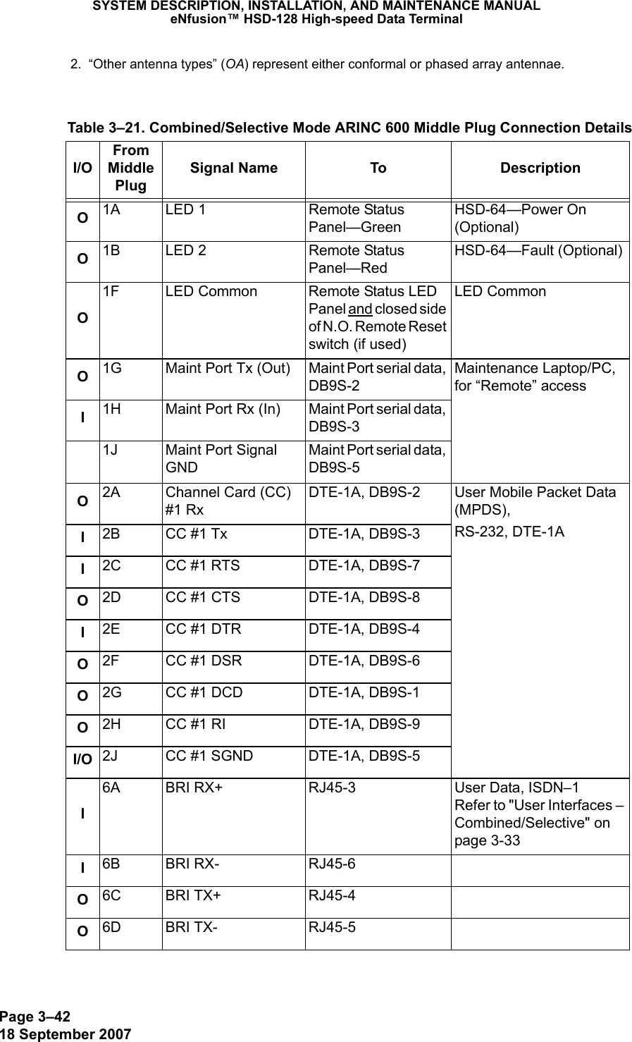
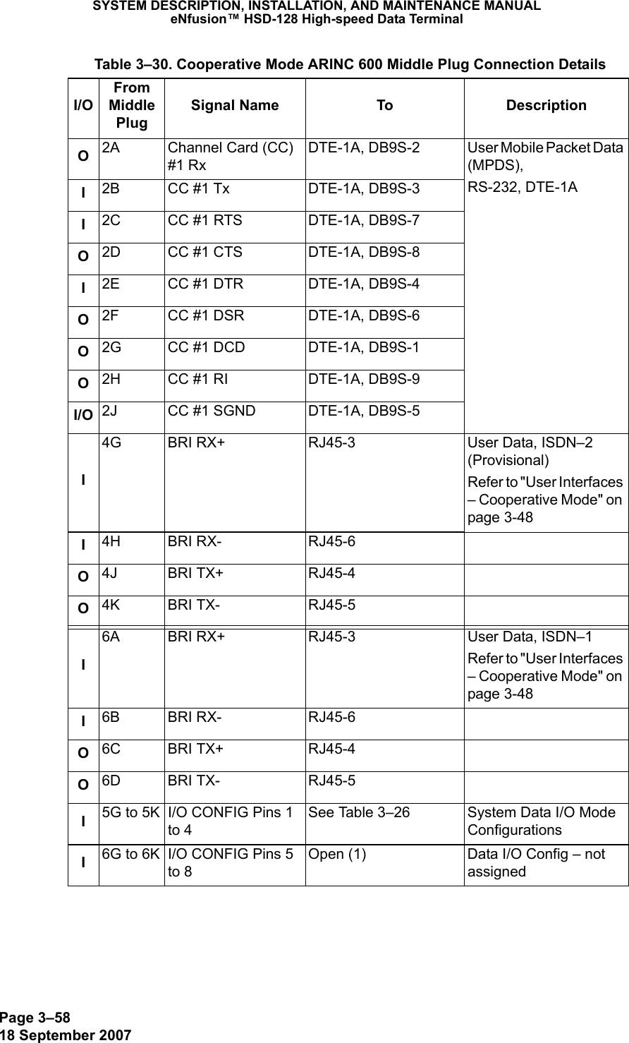
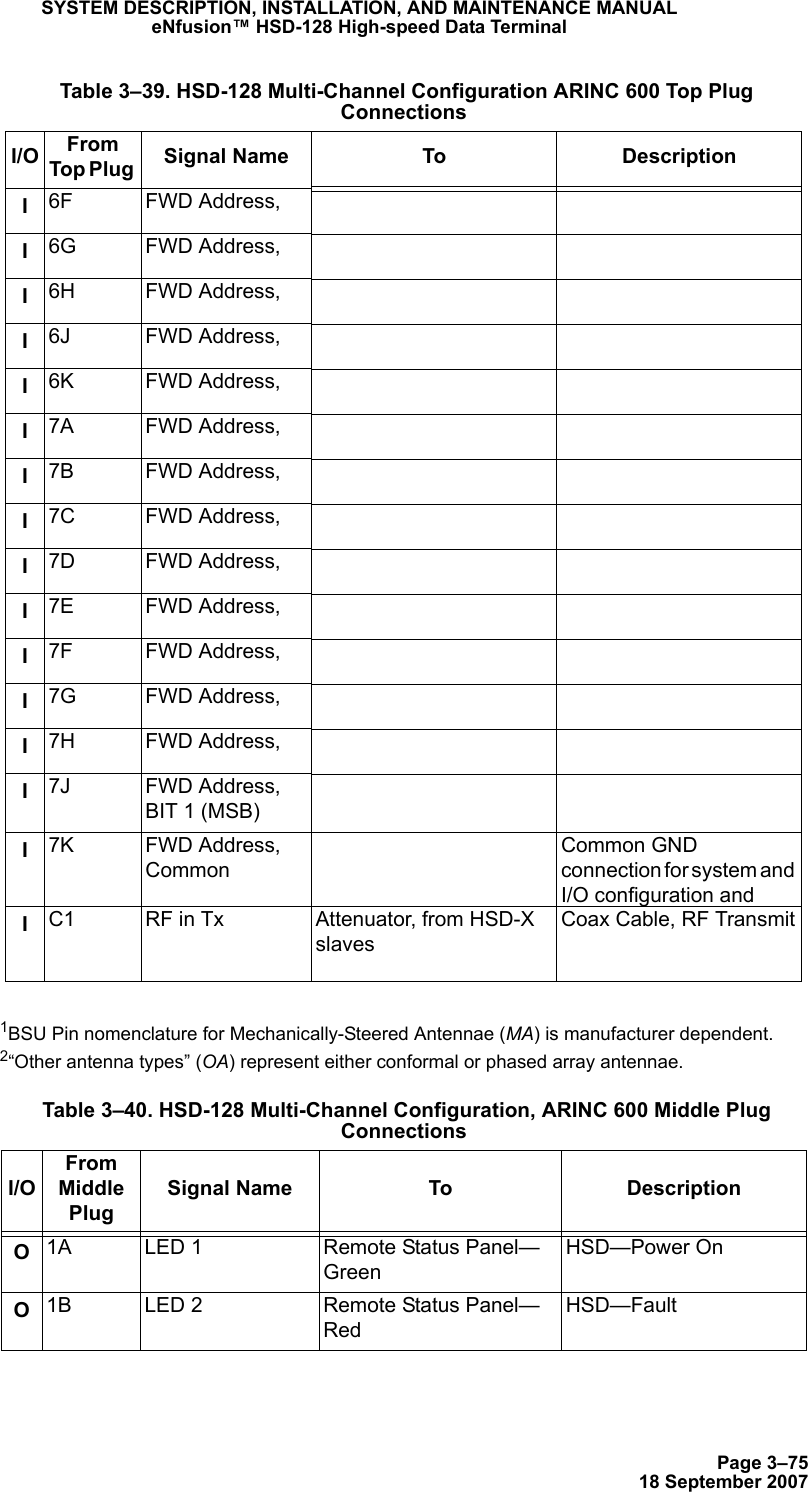
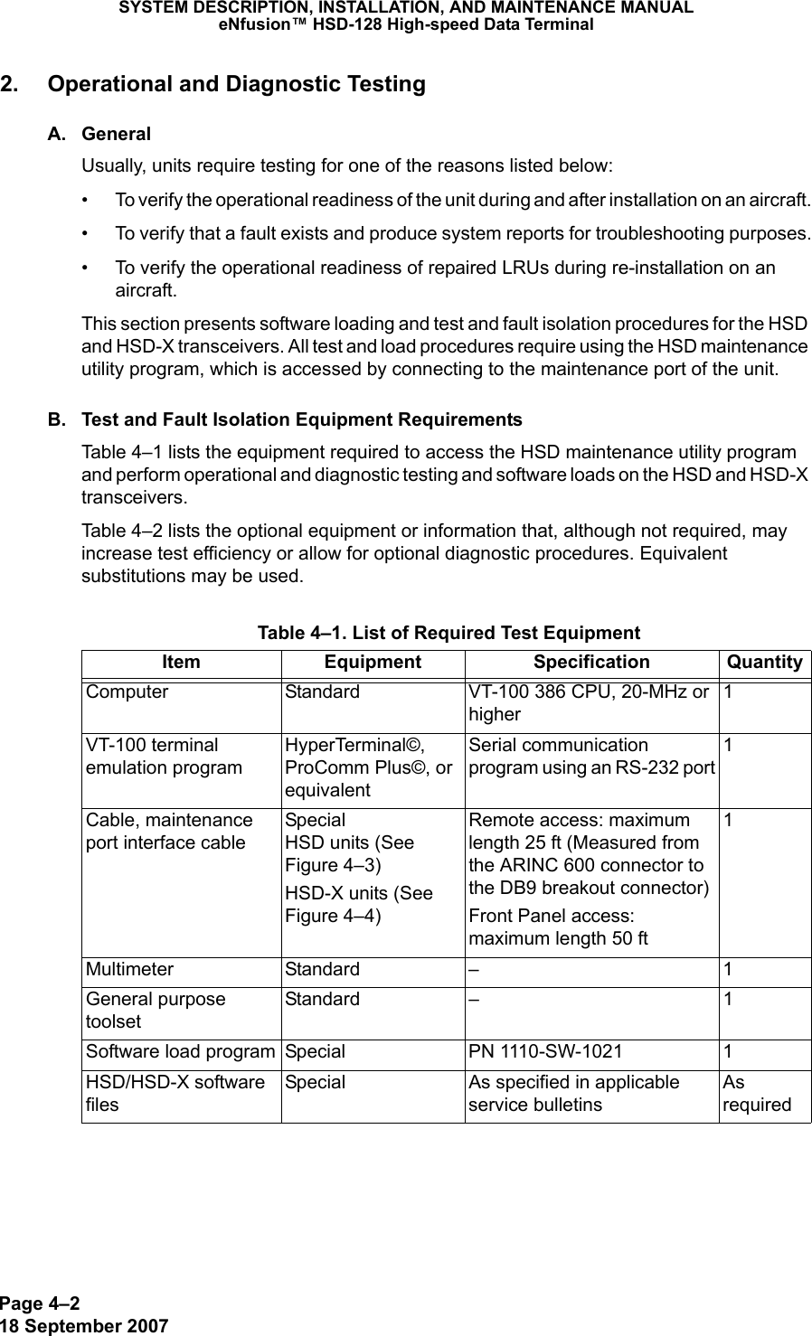
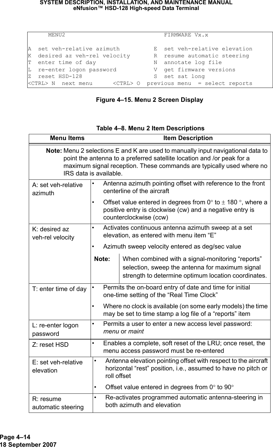
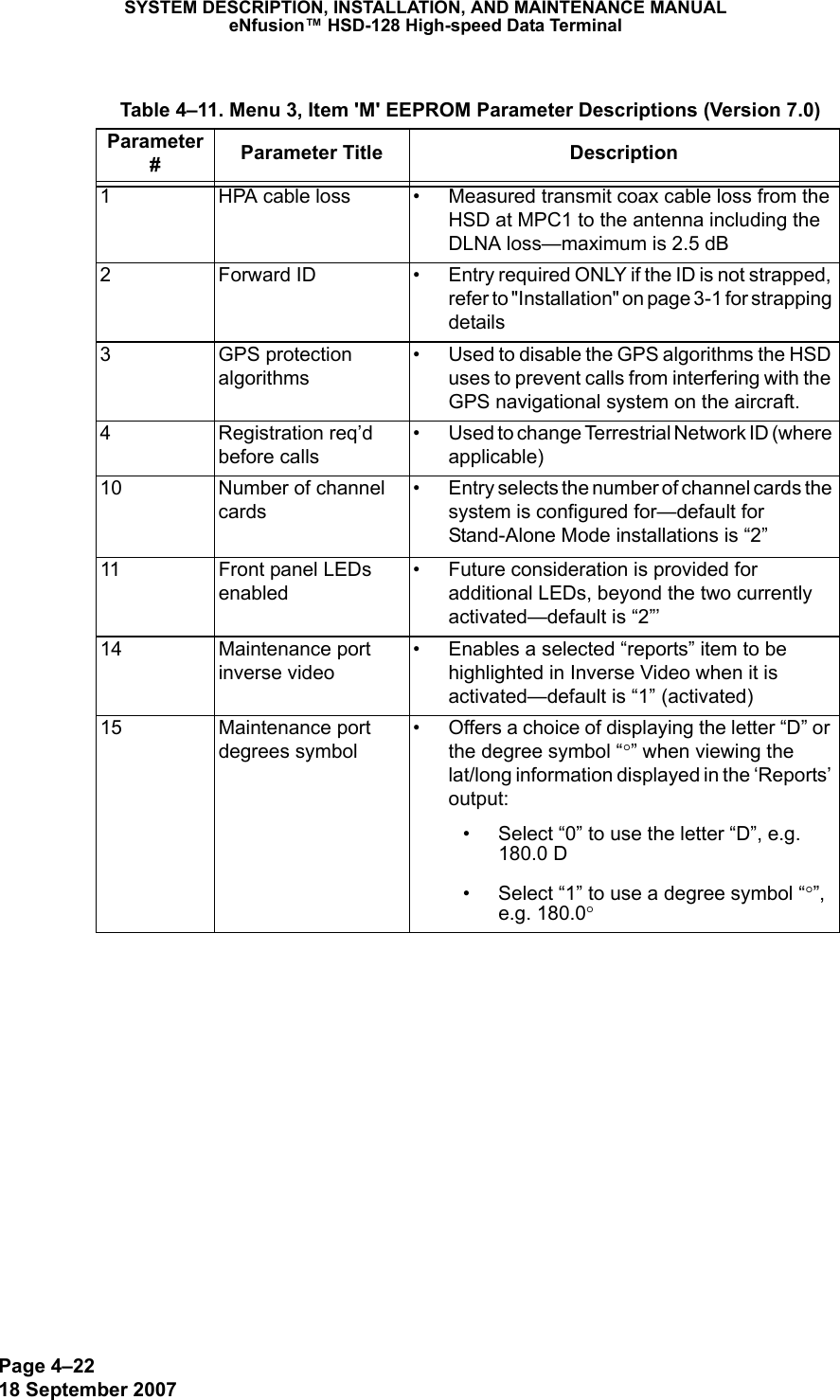
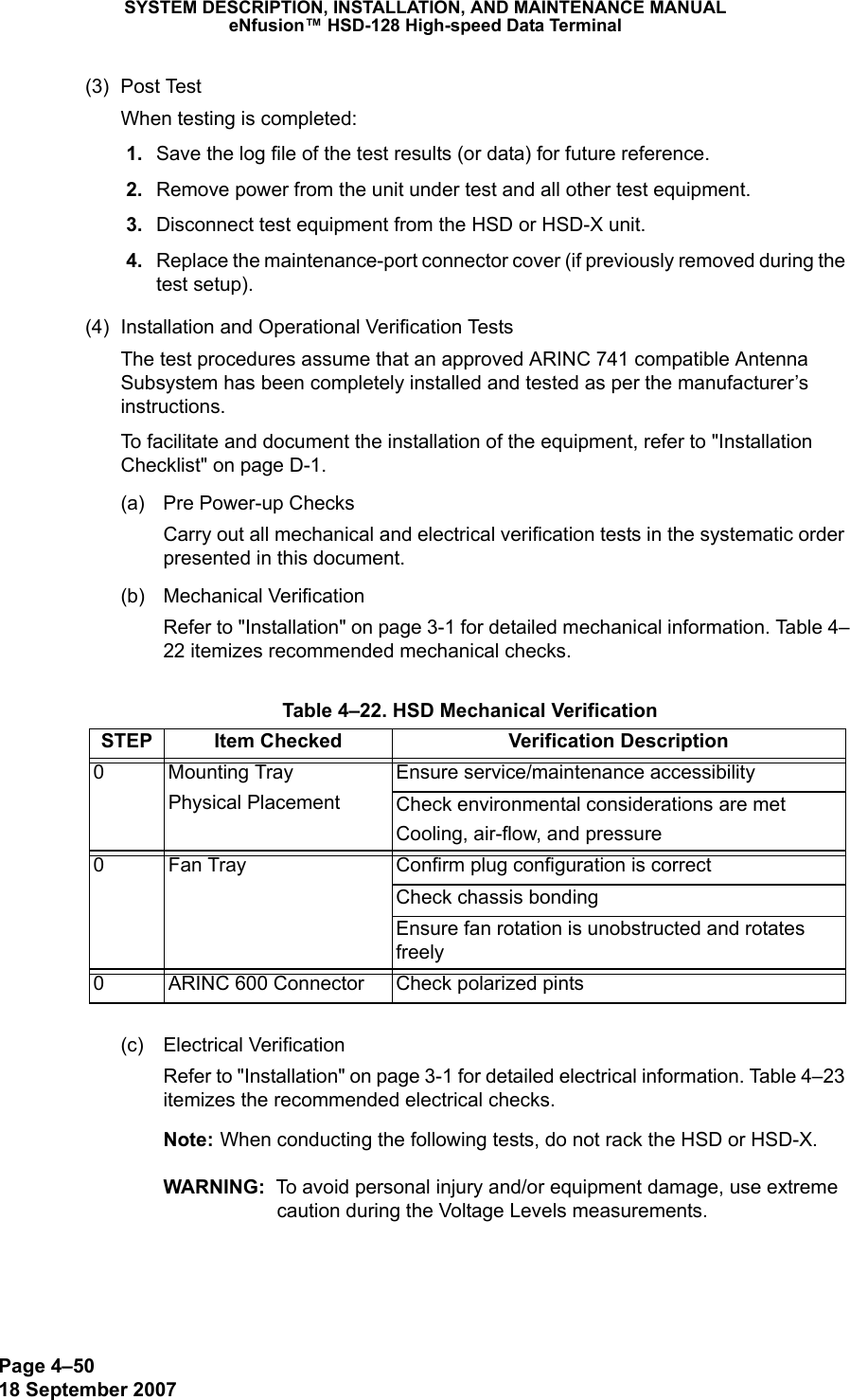
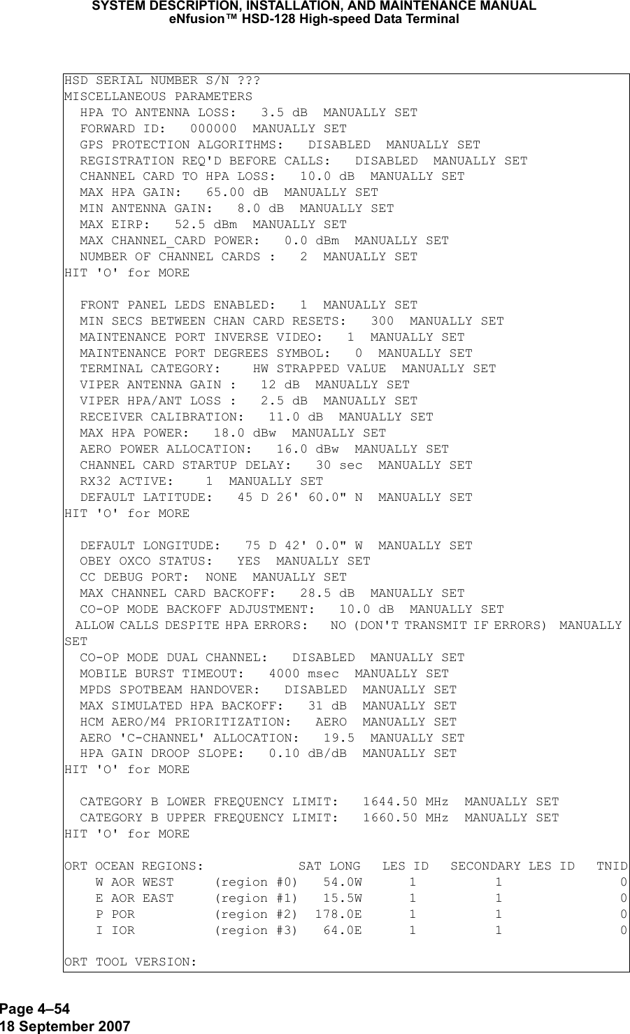
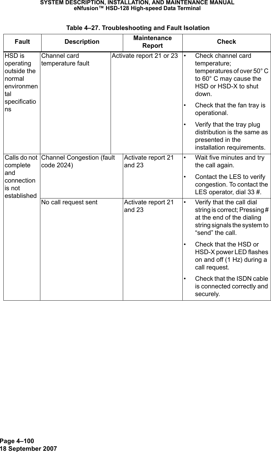
![Page 2–3118 September 2007SYSTEM DESCRIPTION, INSTALLATION, AND MAINTENANCE MANUALeNfusion™ HSD-128 High-speed Data Terminal• Press the reset or remote reset button on all HSD and HSD-X units installed in the system. (Not supported in Cooperative or Combined Mode systems.)When the “reset” or “restart” is completed, the configuration values and parameters are activated. Note: In Multi-Channel configurations, the application prompts the user to select the specific units to reset as shown in the example screen below. • Press Y (for yes) to reset the HSD-X.• Press Y (for yes) to reset the HSD.The configuration values and parameters are now activated. (1) Verifying ConfigurationsThis section describes how to verify or refer to the HSD system configuration parameters. To view the HSD ORT system configuration: 1. In Menu 3, press O.The List ORT appears. 2. Press O to scroll through the listing. To view the new system configurations select “List EEPROM” from Menu 3 1. In Menu 3, press L. 2. The List EEPROM appears. Press L to scroll through the listing. G. Configuring System Parameters using the HSD Owner Requirement ToolHSD transceivers operating version 7.0 (or later) control processor software and HSD-X transceivers operating control processor software 6.0, (or later) both support system configuration using the HSD ORT Tool (PN 1110-SW-1047). The HSD Owner Requirements Table (ORT) Tool application is available from EMS Technologies. Contact EMS SATCOM Product Support for more information.The ORT Tool is a Windows-based program that is used to create and change system configuration disks or files for the HSD system. The configuration data files, created using the ORT Tool, are either loaded into the HSD and HSD-X transceivers via the RS-232 maintenance port interface using an HSD load program or loaded using the self-extracting option of the HSD ORT application. MENU 2 FIRMWARE Vx.xA set veh-relative azimuth E set veh-relative elevationK desired az veh-rel velocity R resume automatic steeringT enter time of day N annotate log fileL re-enter logon password V get firmware versionsZ reset HSD-128 S set satellite longitude<CTRL> N next menu <CTRL> O previous menu = select reportsTERMINAL: HSD-X NETWORK MODE HSD-X (y/n) [n] ? HSD (y/n) [n] ?](https://usermanual.wiki/EMS-Technologies-Canada/HSD-X/User-Guide-1275806-Page-107.png)
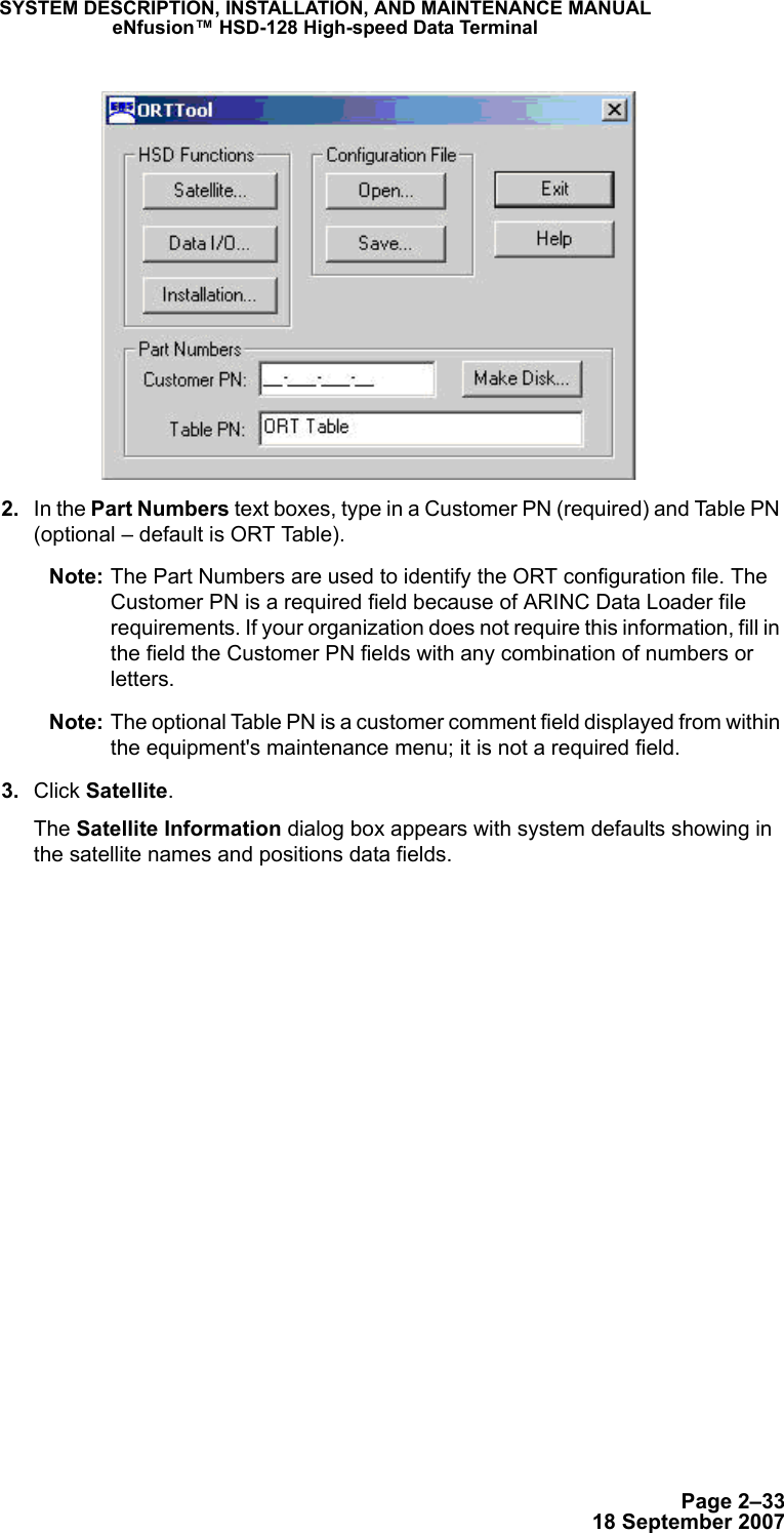
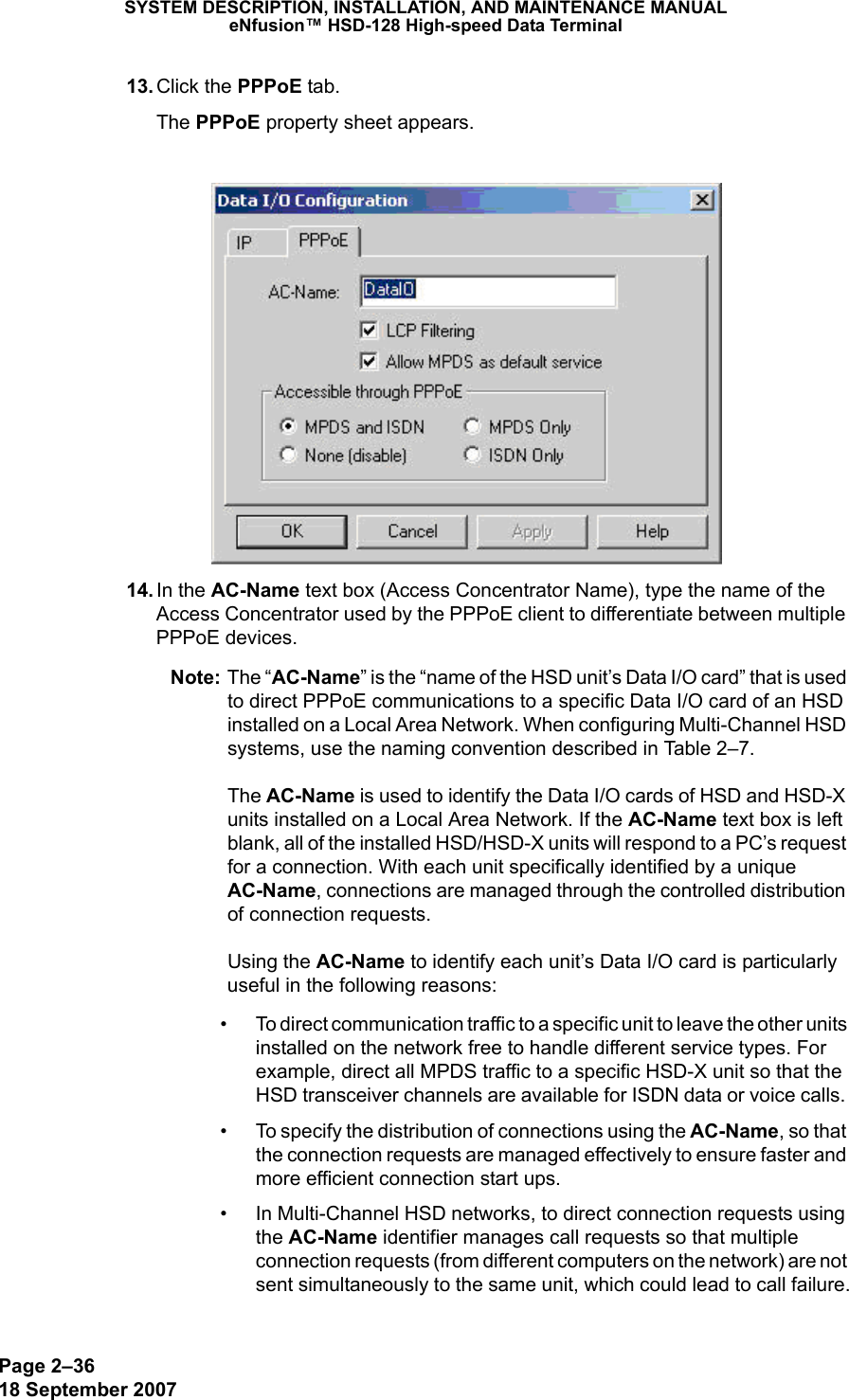
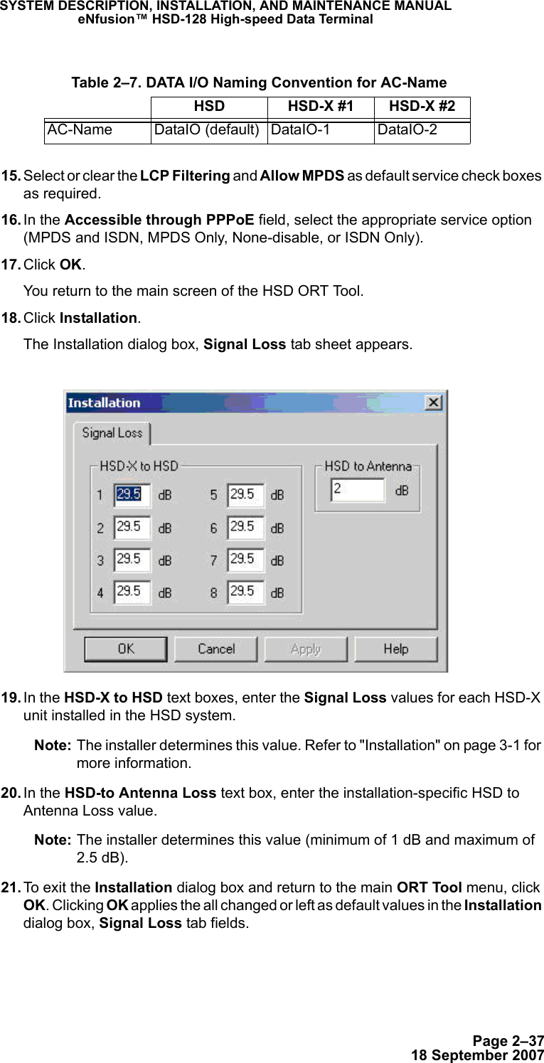
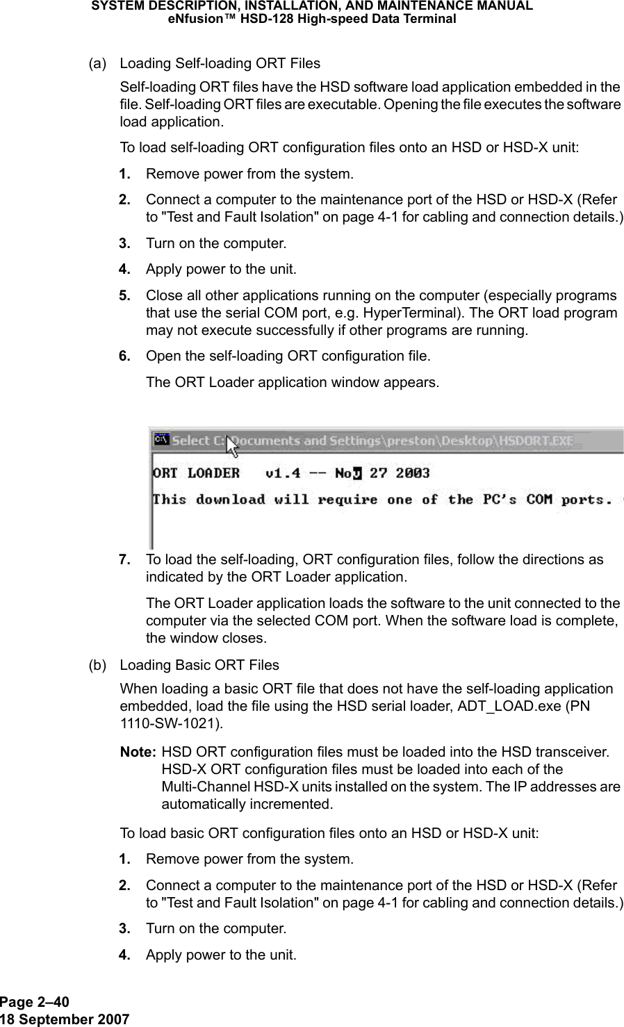
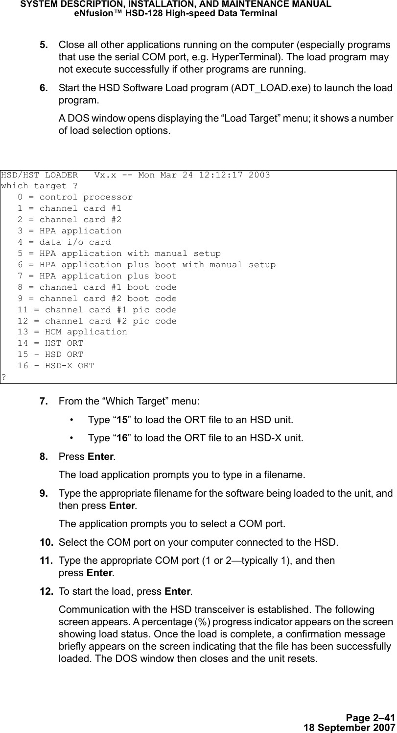
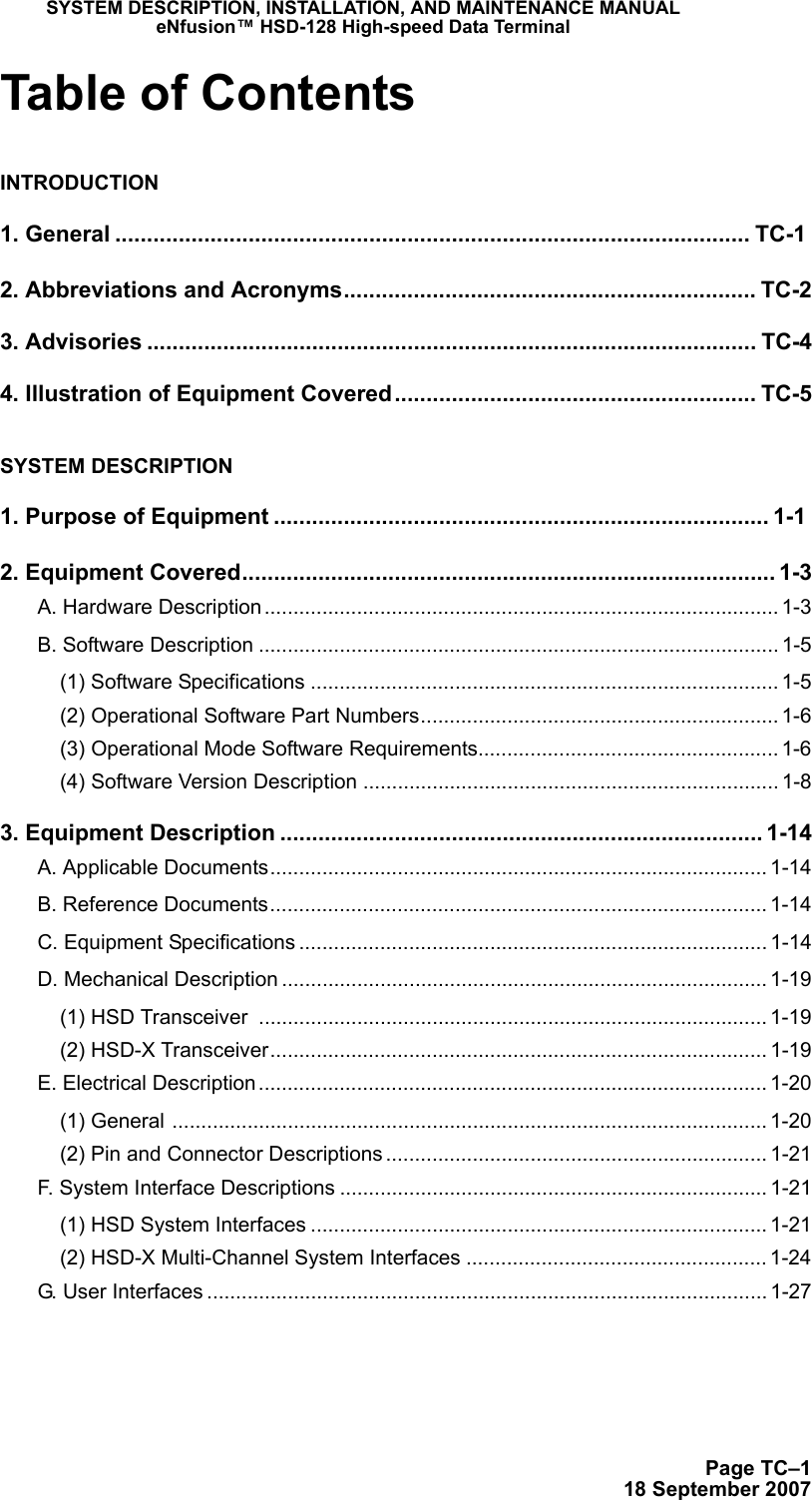
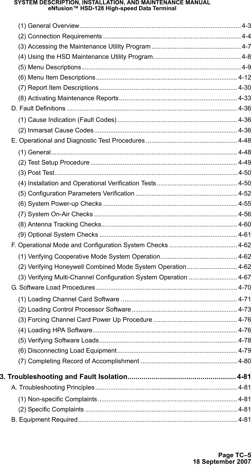
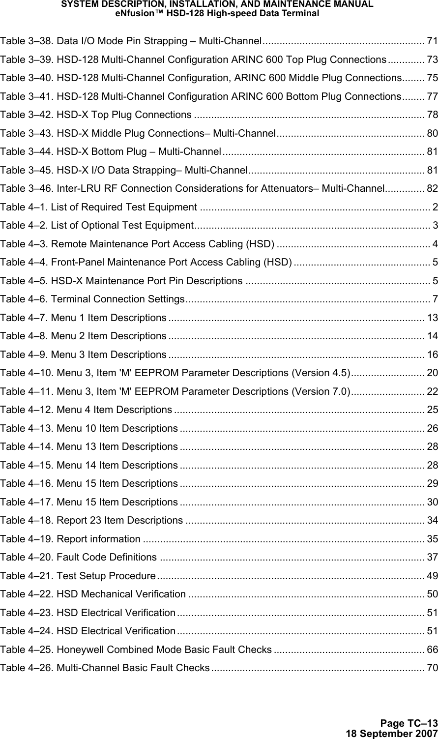
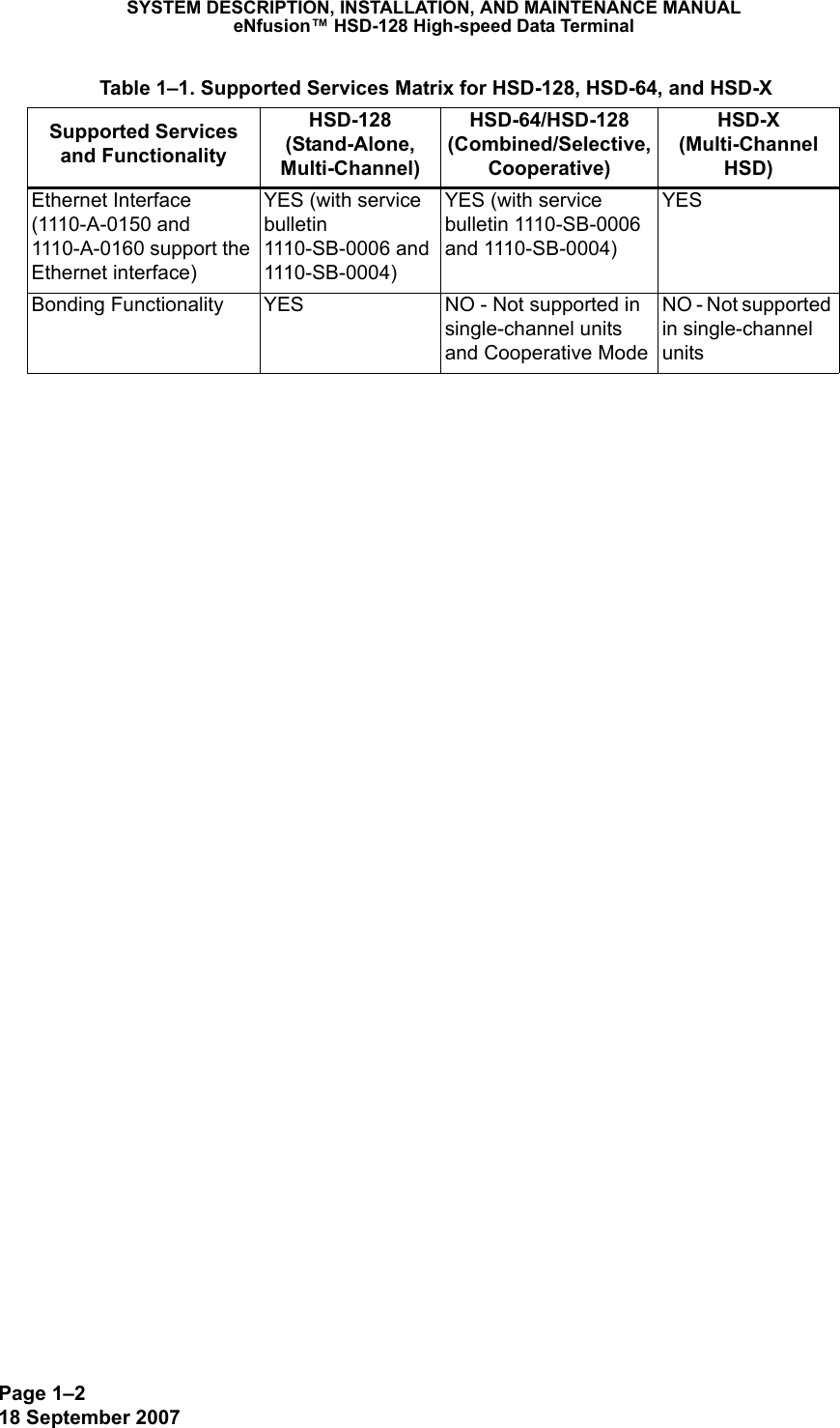
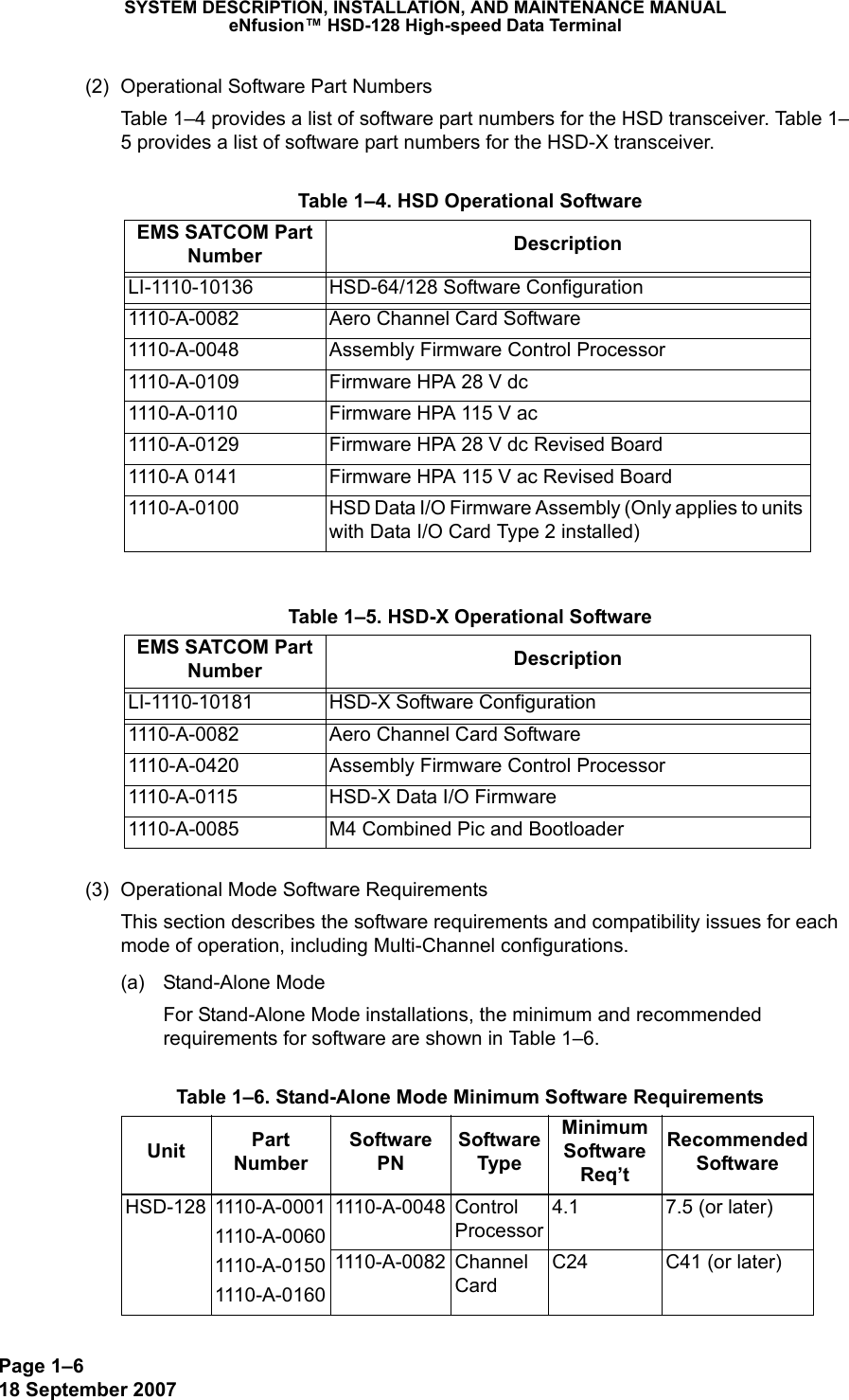
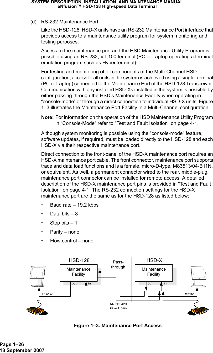
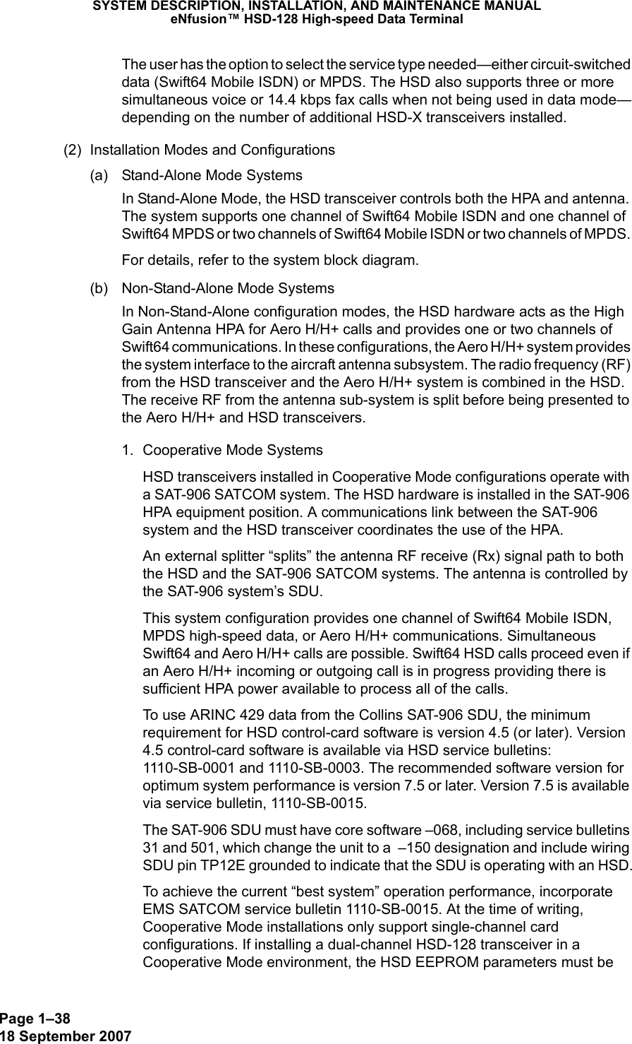
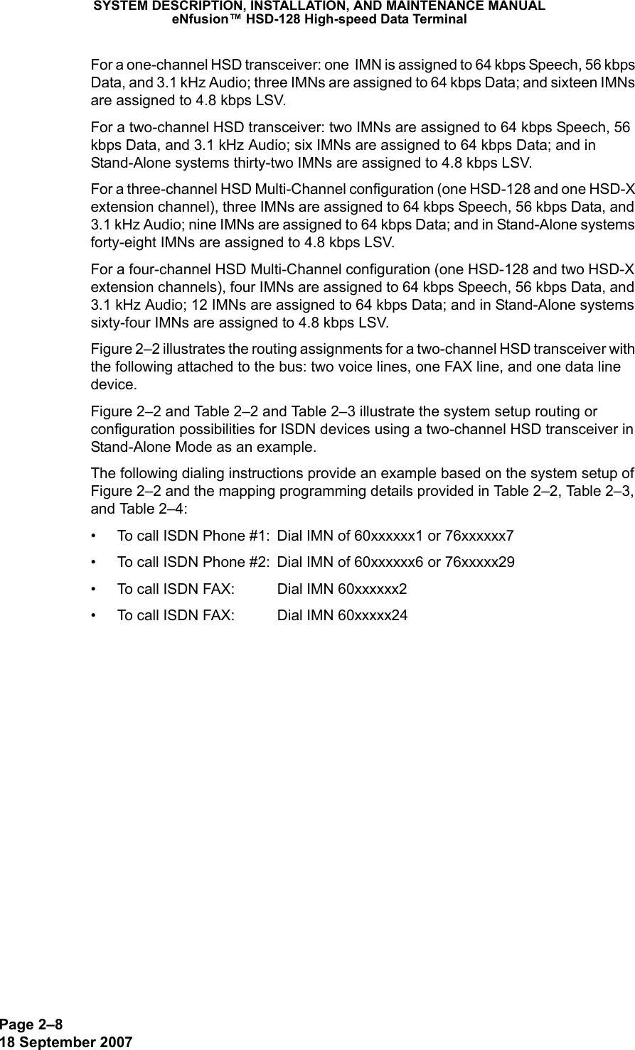
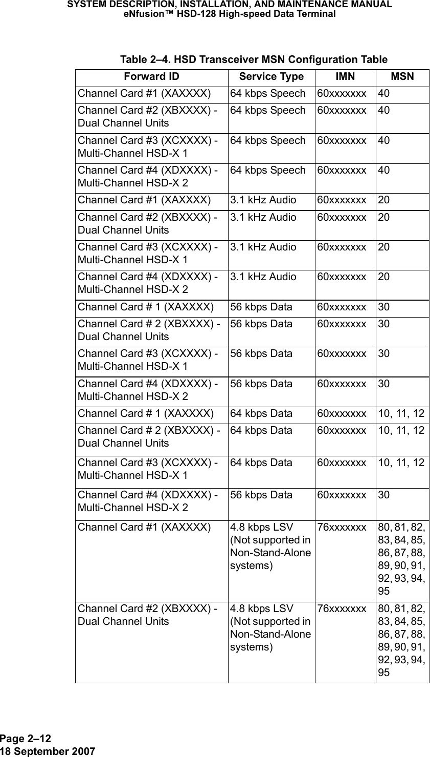
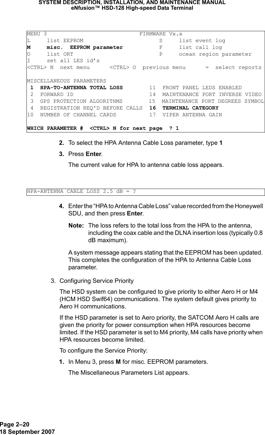
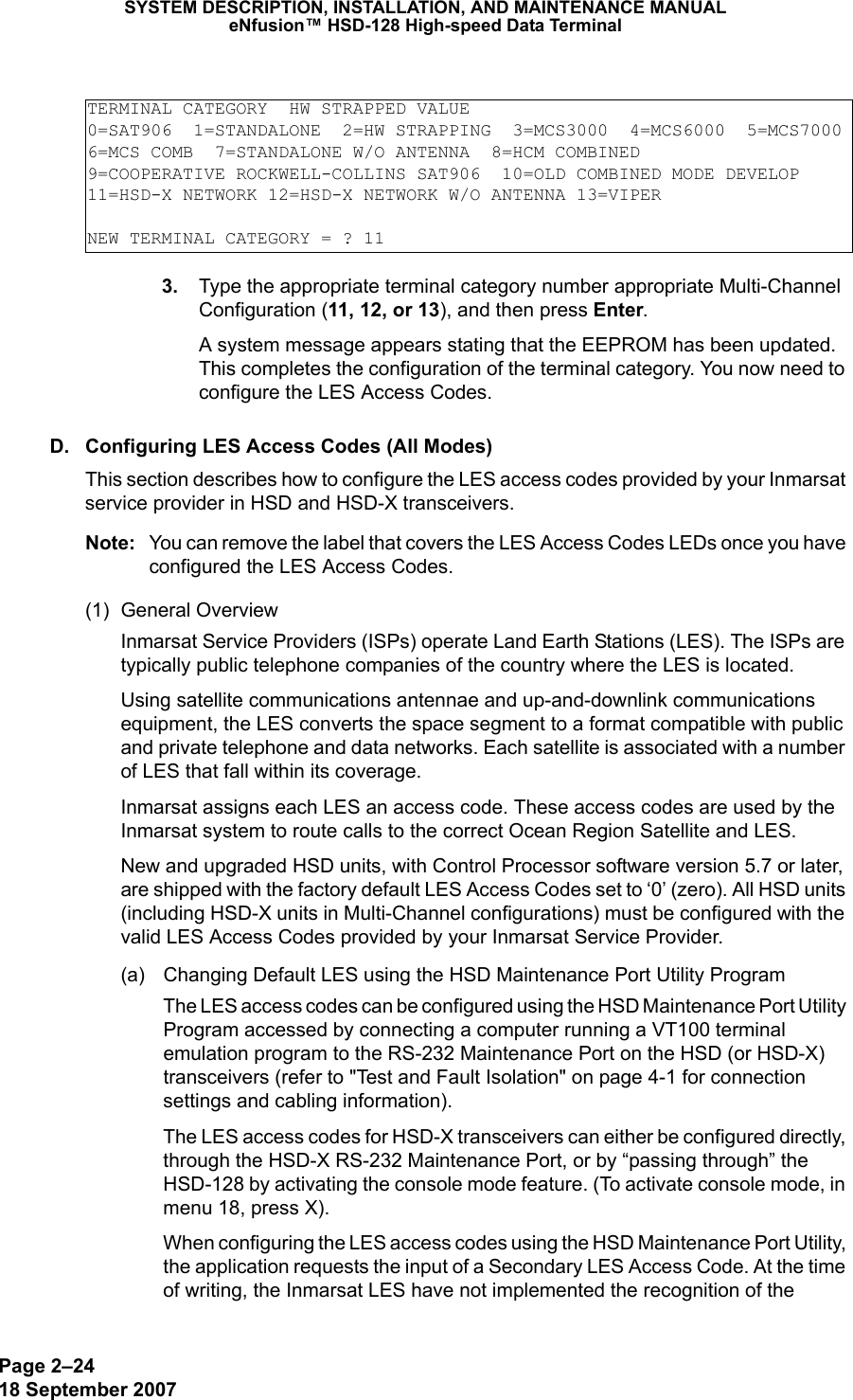
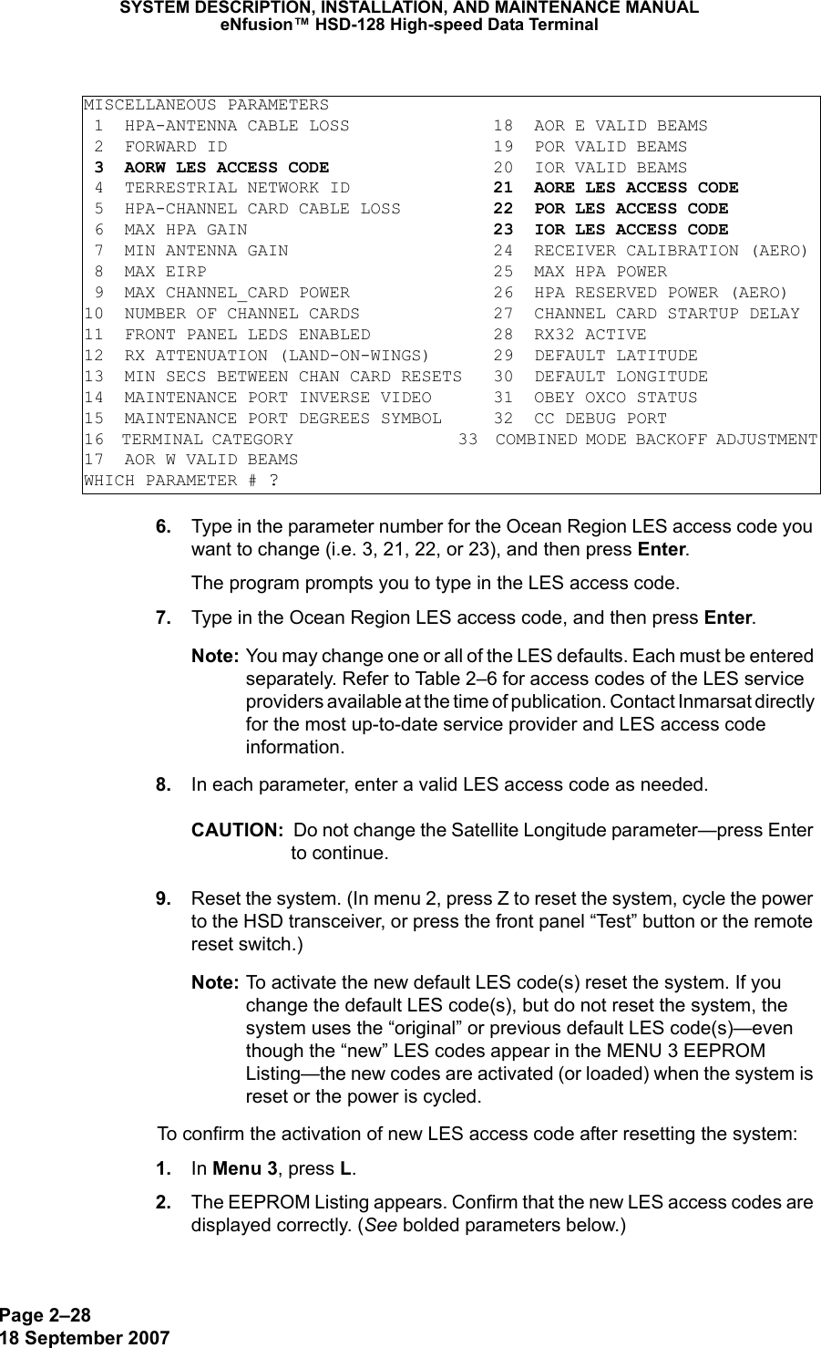
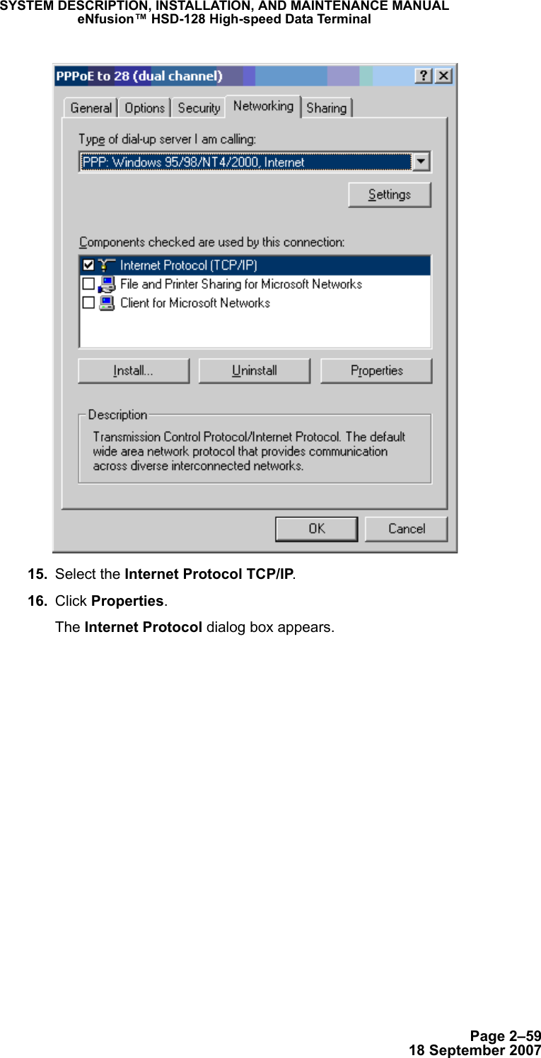
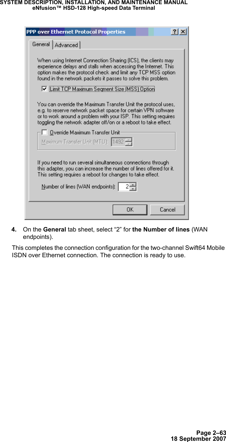
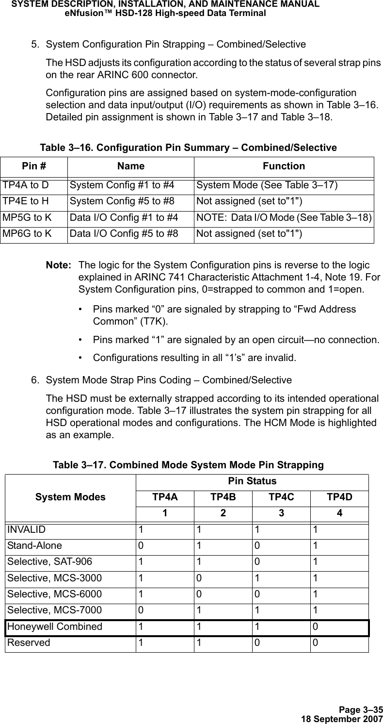
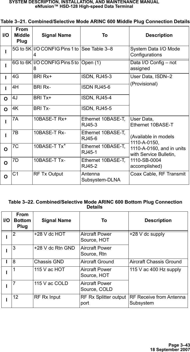
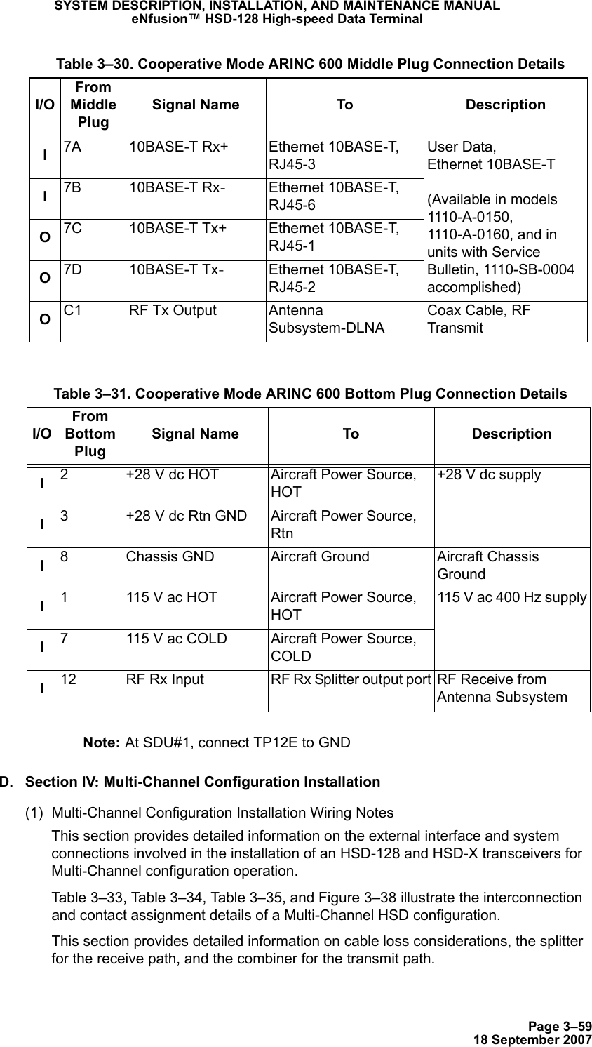
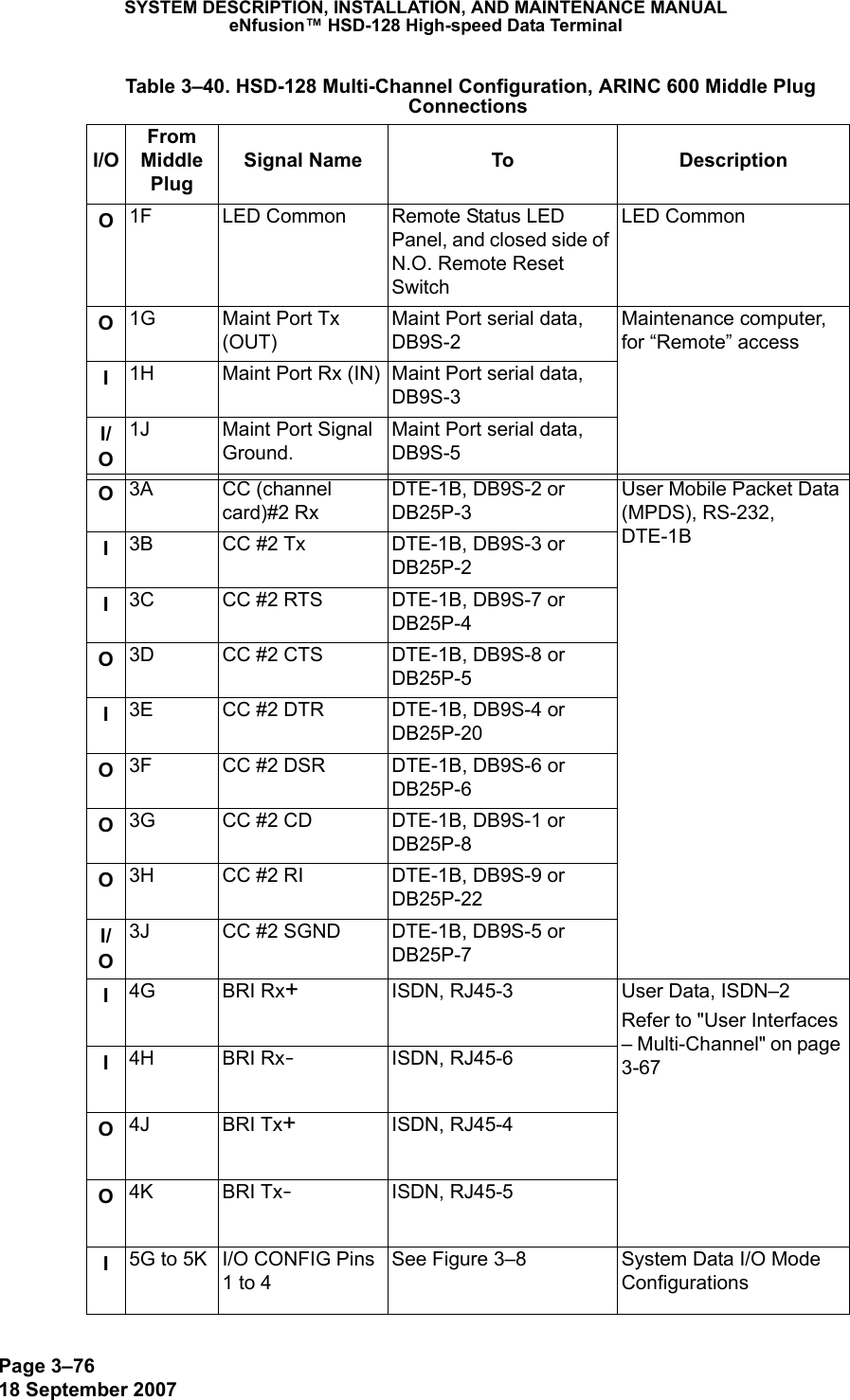
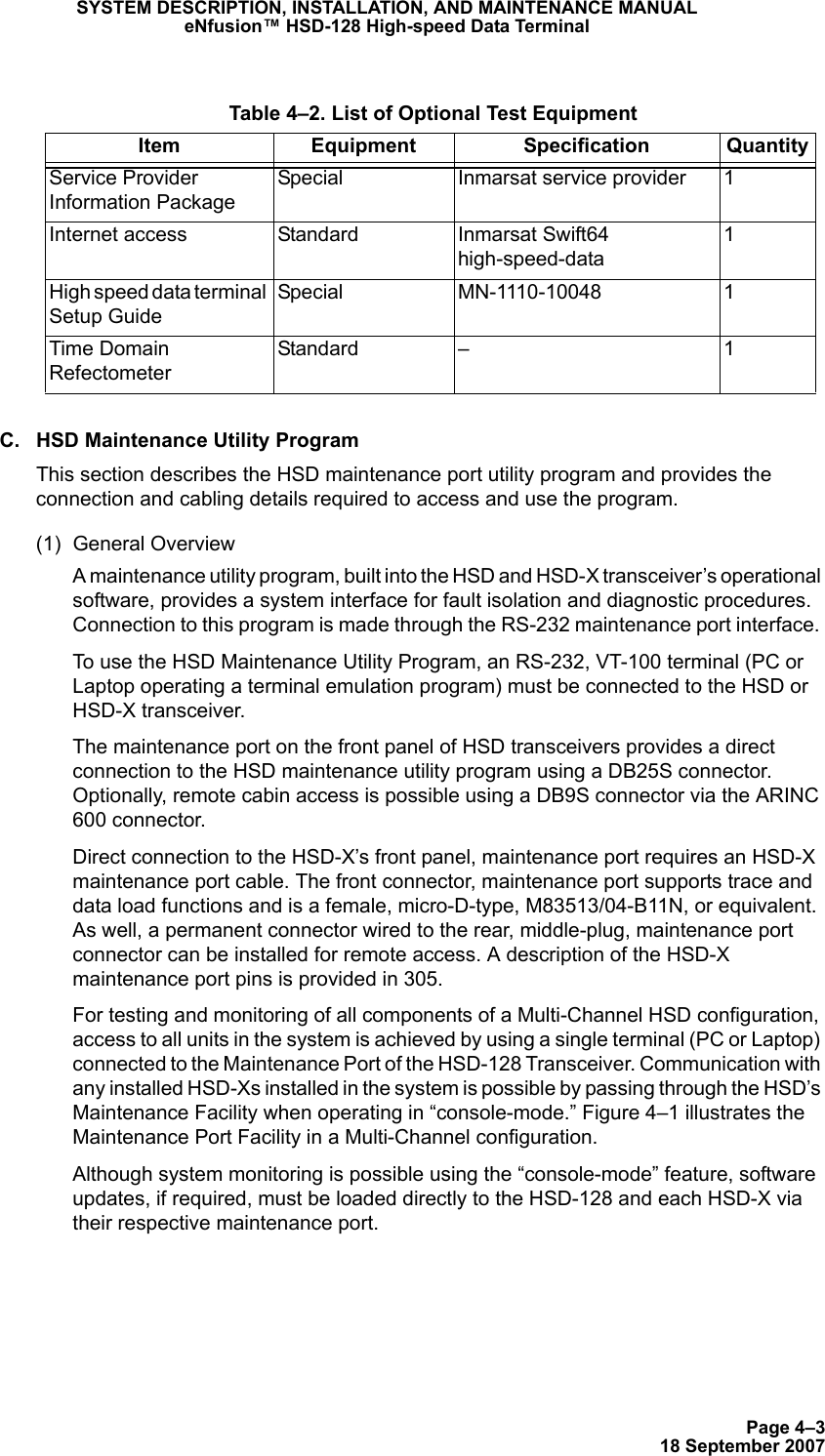
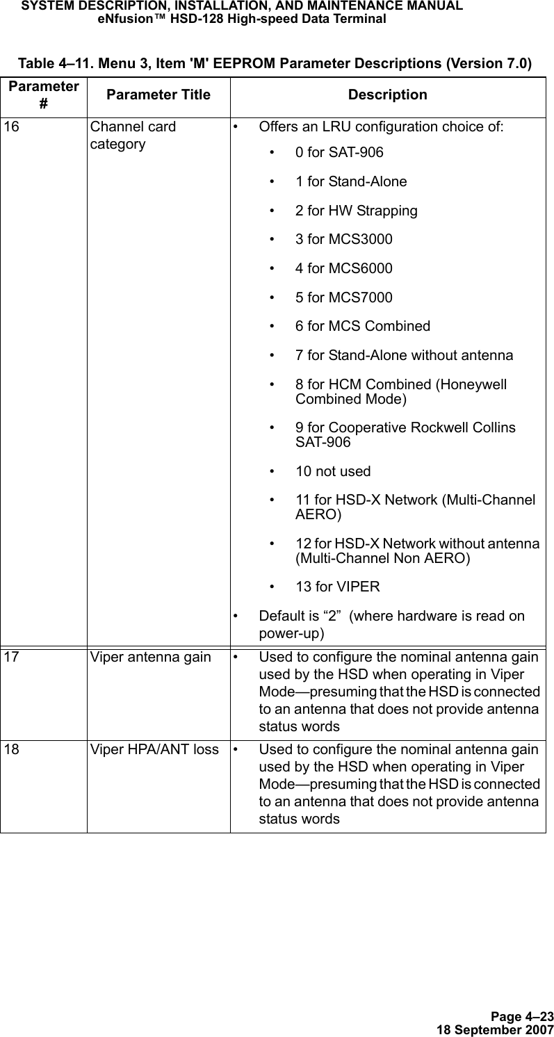
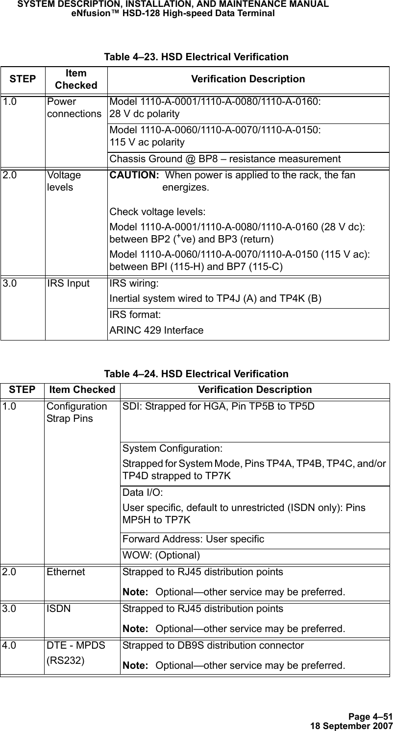
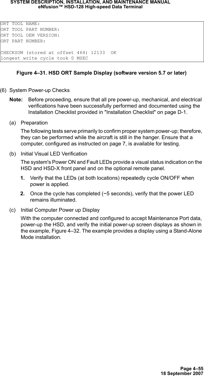
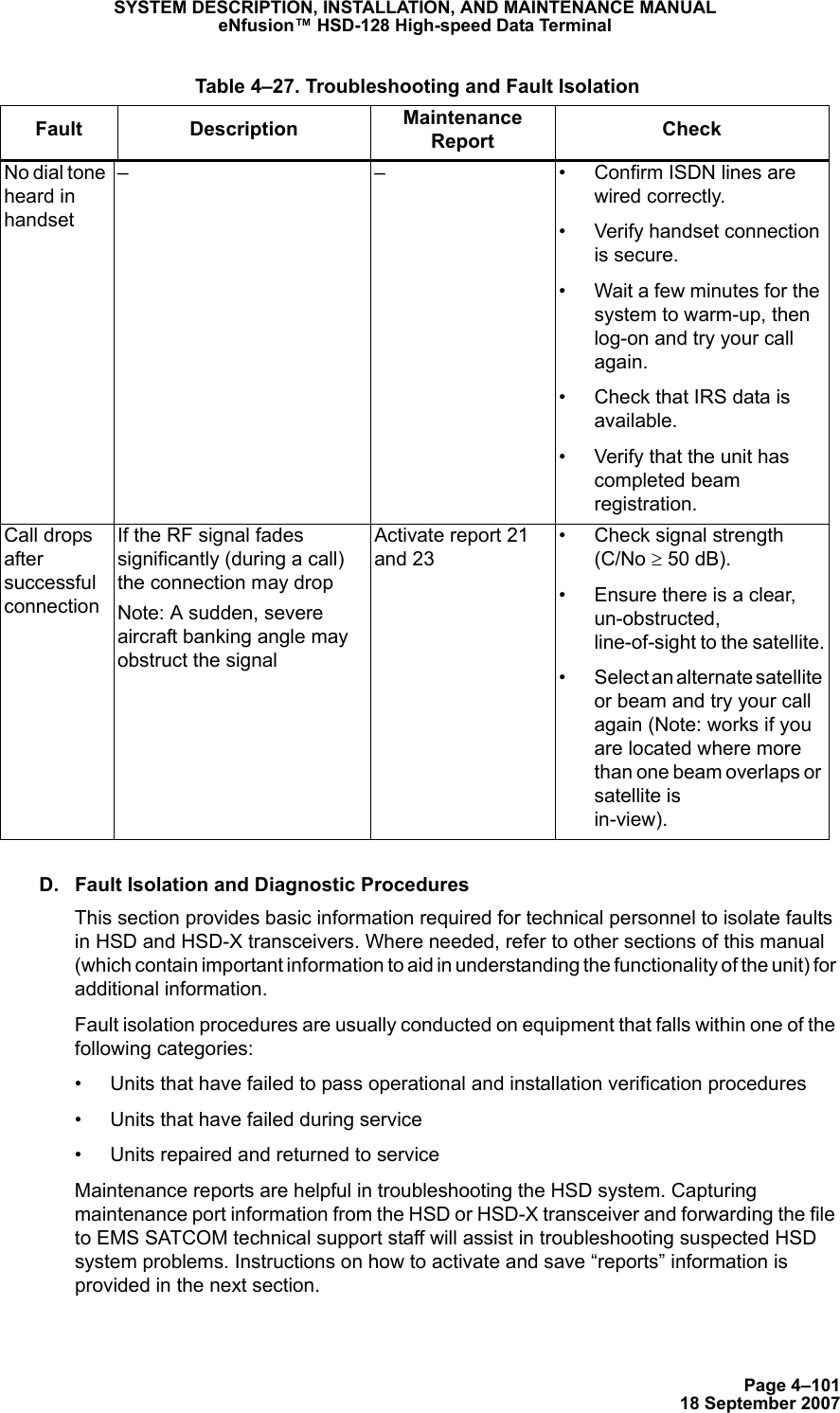
![Page 2–4218 September 2007SYSTEM DESCRIPTION, INSTALLATION, AND MAINTENANCE MANUALeNfusion™ HSD-128 High-speed Data TerminalHSD/HST LOADER Vx.x – [Date]which target ? 0 = control processor 1 = channel card #1 2 = channel card #2 3 = HPA application 4 = data i/o card 5 = HPA application with manual setup 6 = HPA application plus boot with manual setup 7 = HPA application plus boot 8 = channel card #1 boot code 9 = channel card #2 boot code 11 = channel card #1 pic code 12 = channel card #2 pic code 13 = HCM application 14 = HST ORT 15 = HSD ORT 16 = HSD-X ORT? File name which contains the firmware image? This download will require one of the PC's COM ports. (1, 2, etc) [1] ? Connect COM1 of this PC to the maintenance port of the data terminal.Hit <ESC> to abort, or <ENTER> to proceedEstablishing communication to the data terminal -- DO NOT CYCLE THE POWER!!Hit ESC to abort.DATA TERMINAL APPARENTLY READY TO ACCEPT PROGRAMswitching to 57.6 kbaudloading c:\ort\hsd.ort 67% 100%DATA TRANSFER COMPLETE -- 0 SECONDSdio state 1DATA TRANSMITTED: 1506 BYTES CHECKSUM = 13D9FHSD/HST LOADER Vx.x – [Date]](https://usermanual.wiki/EMS-Technologies-Canada/HSD-X/User-Guide-1275806-Page-118.png)

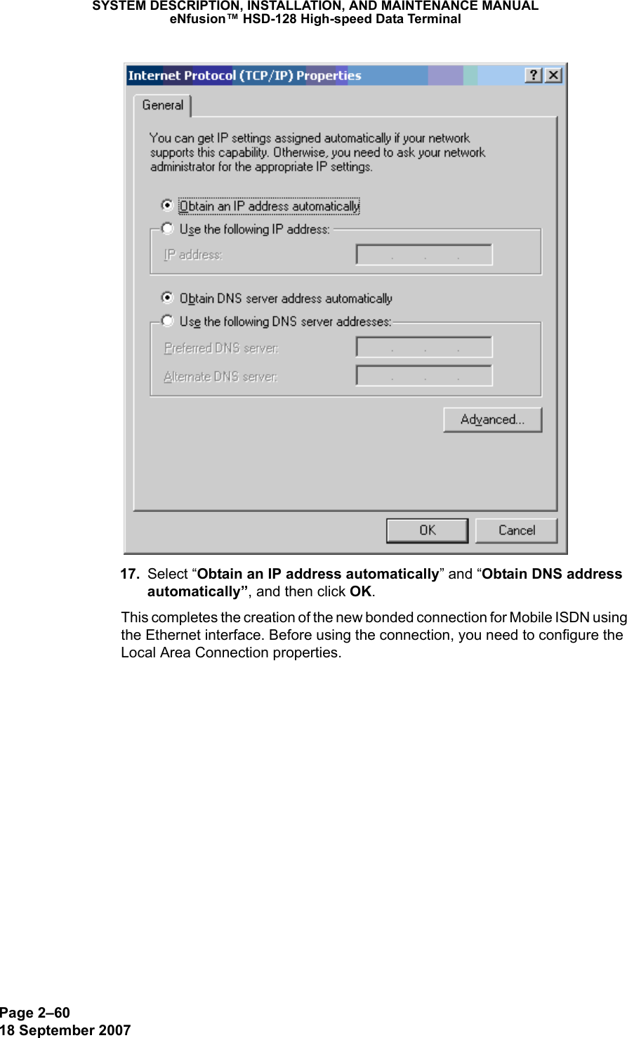
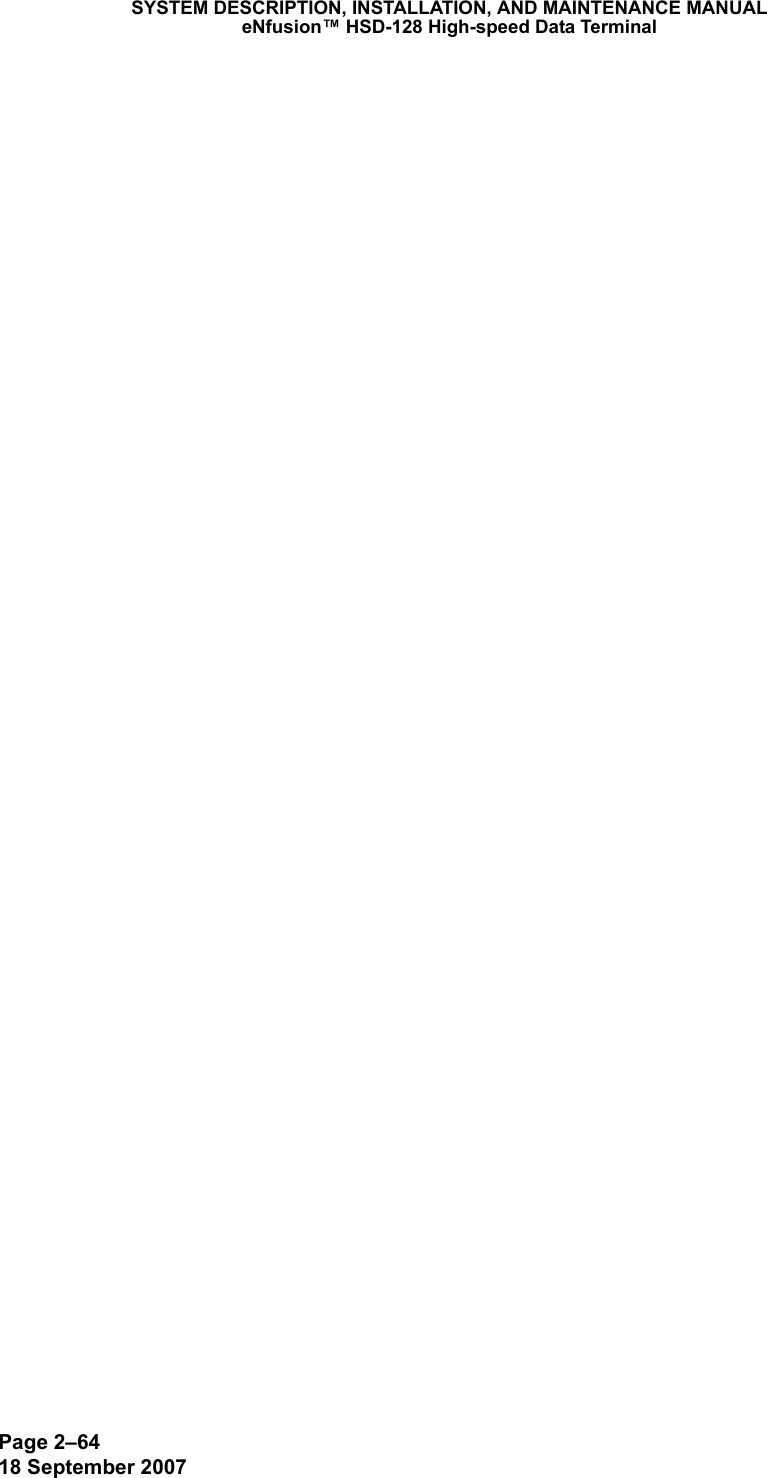

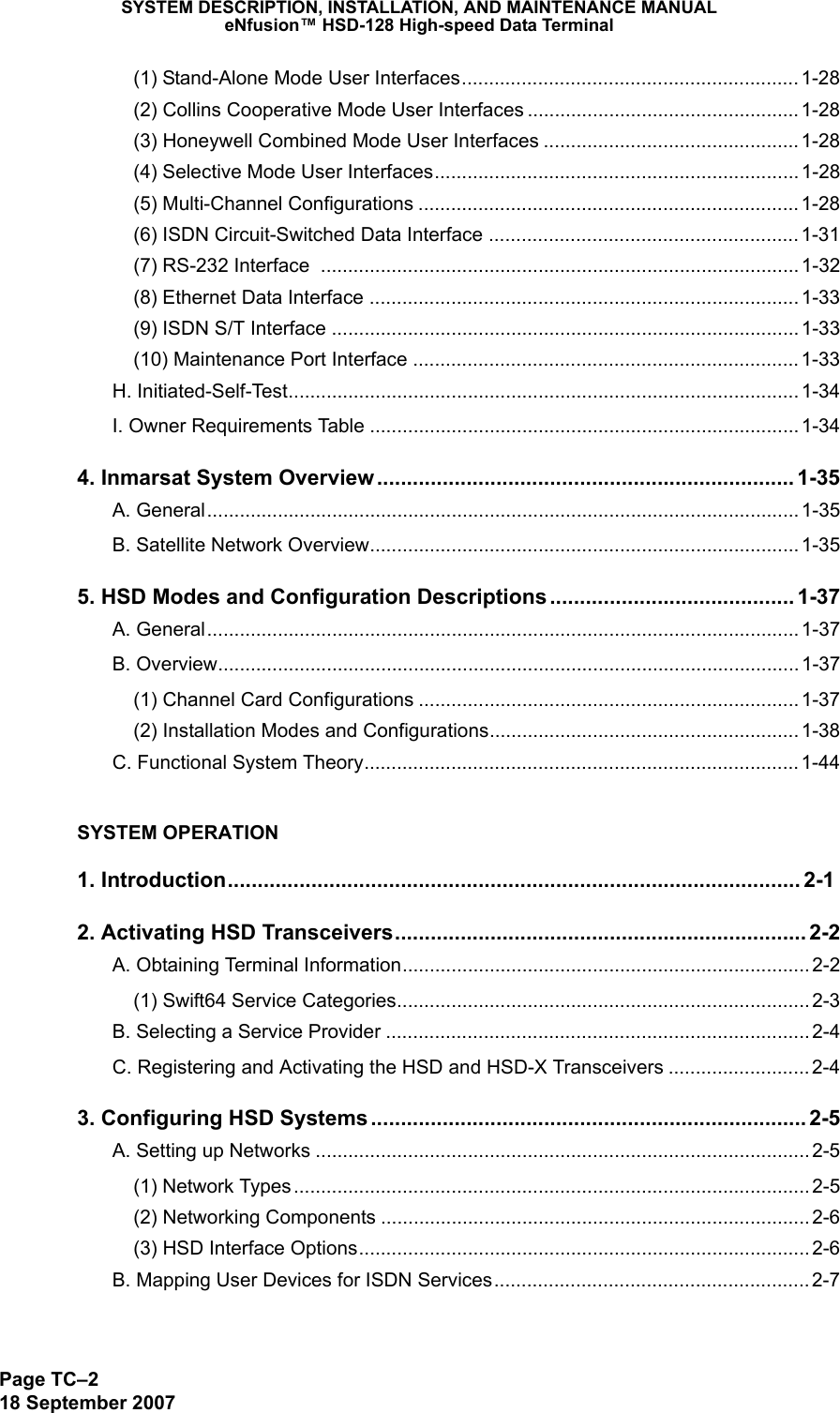
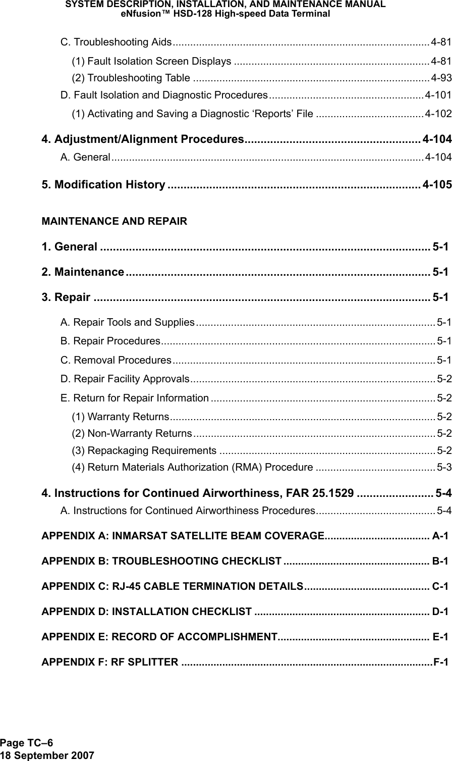
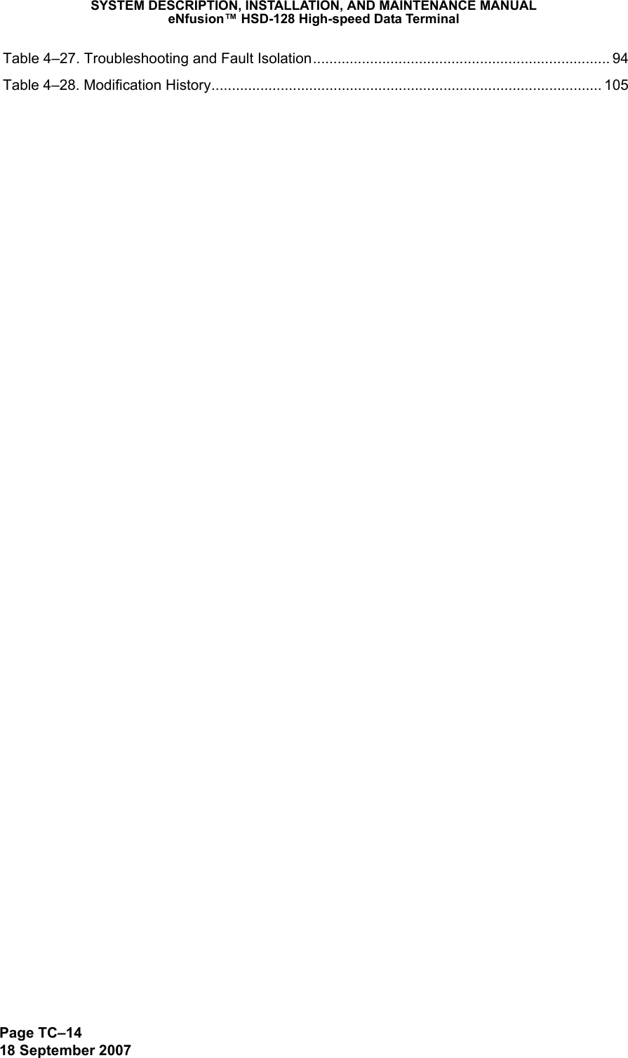
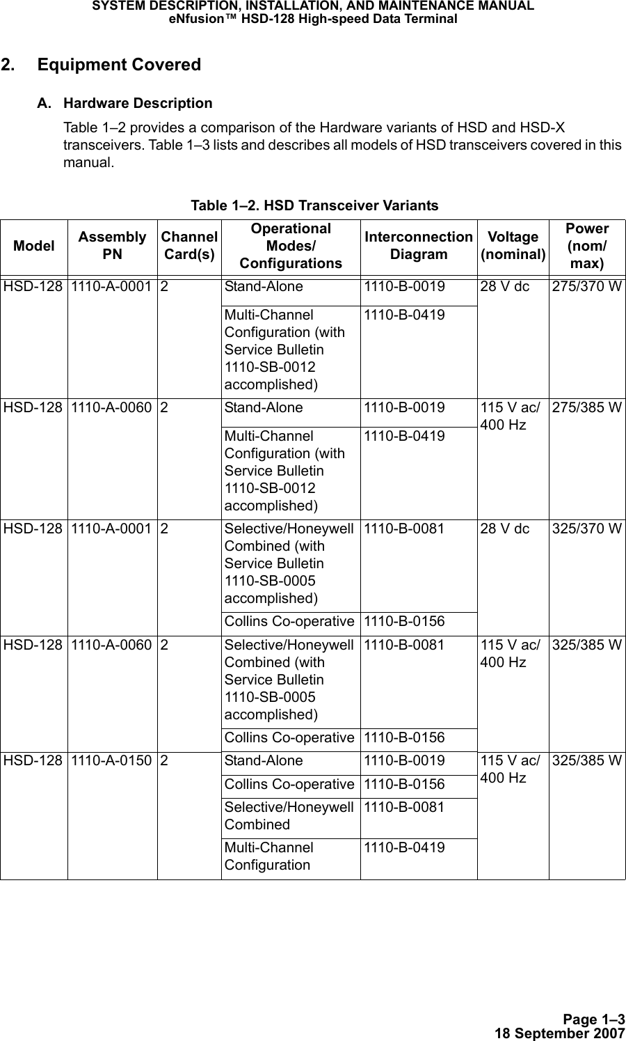
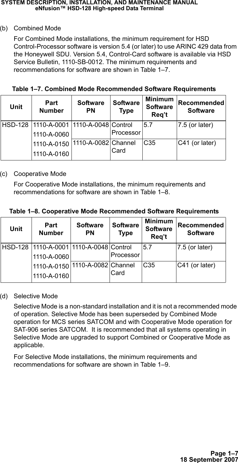
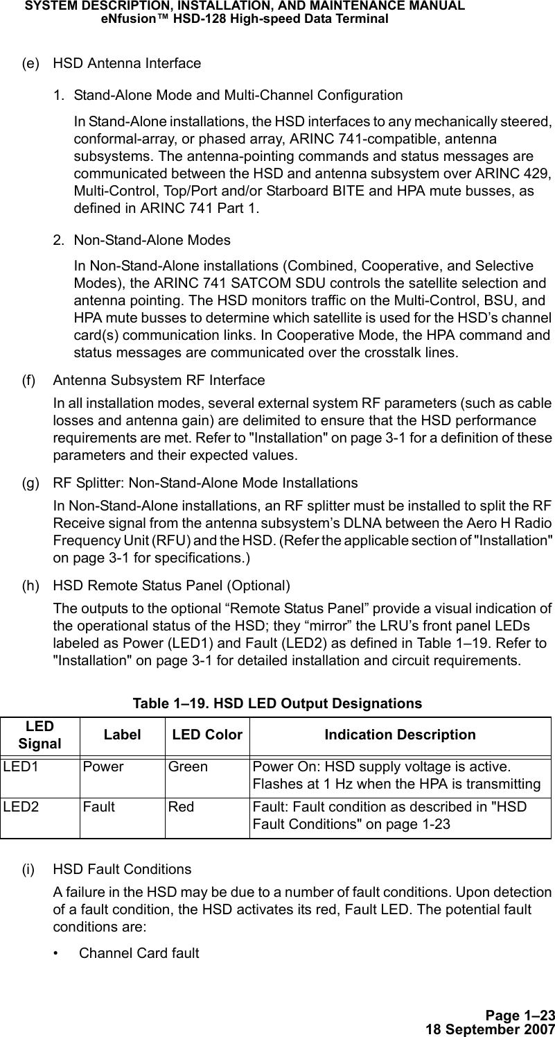
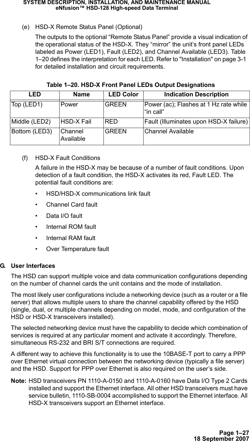
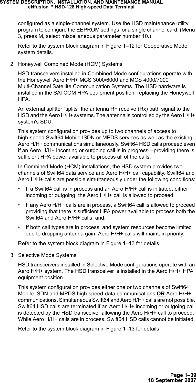
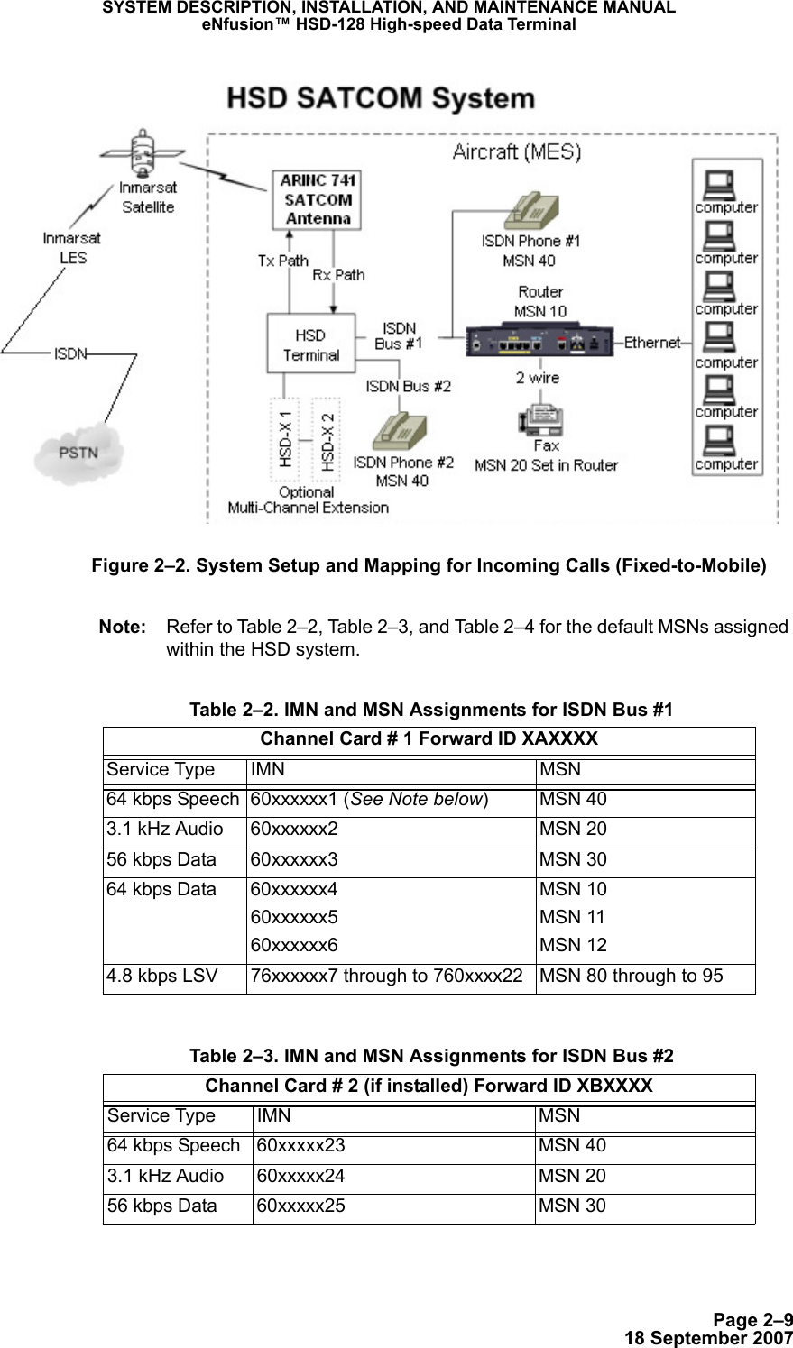
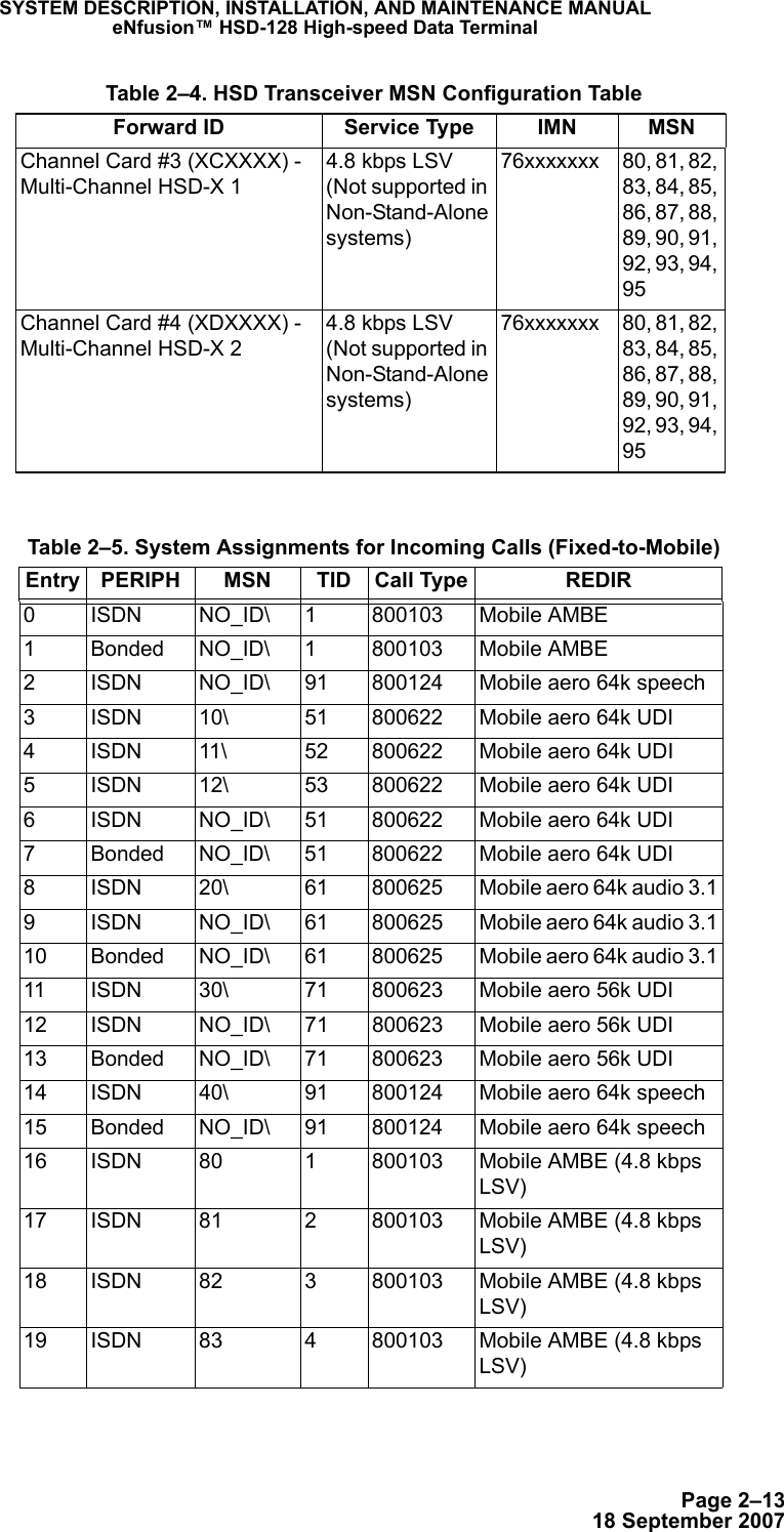
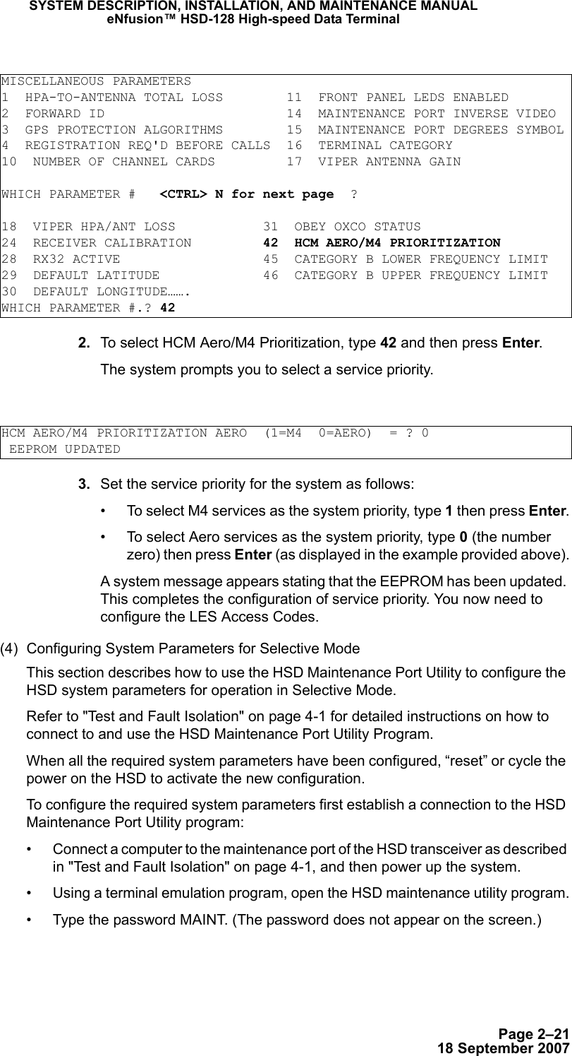
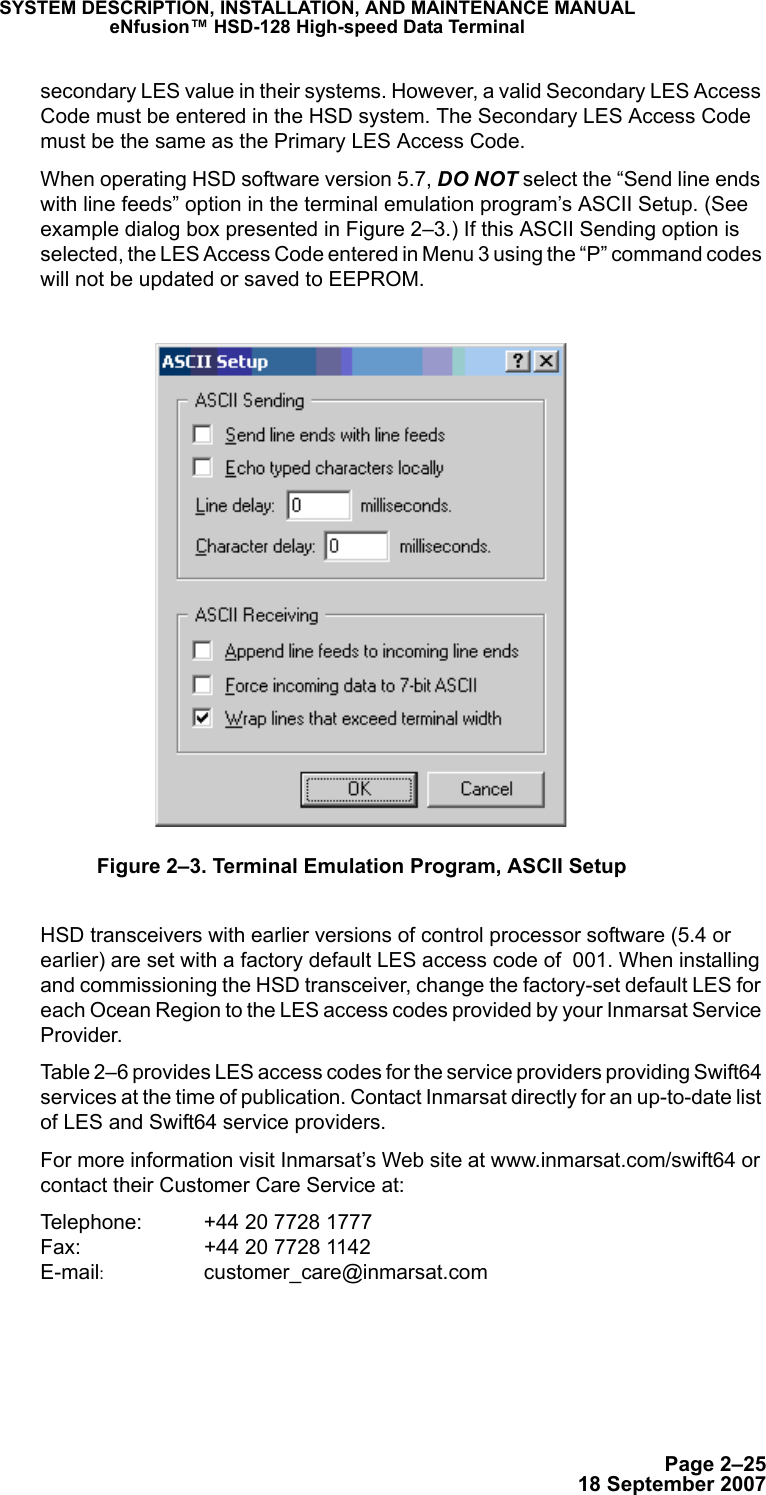
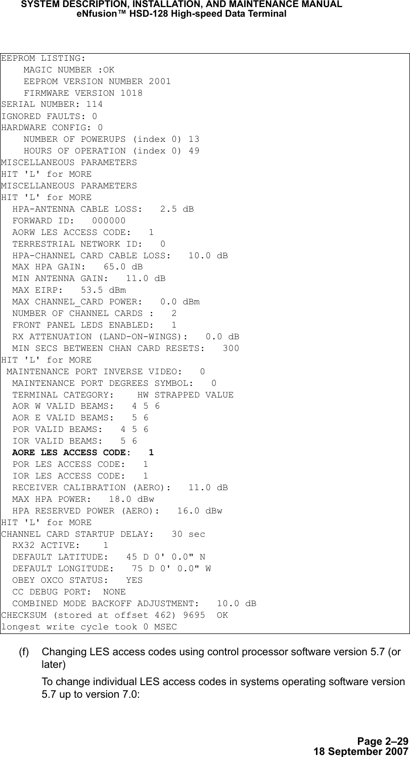
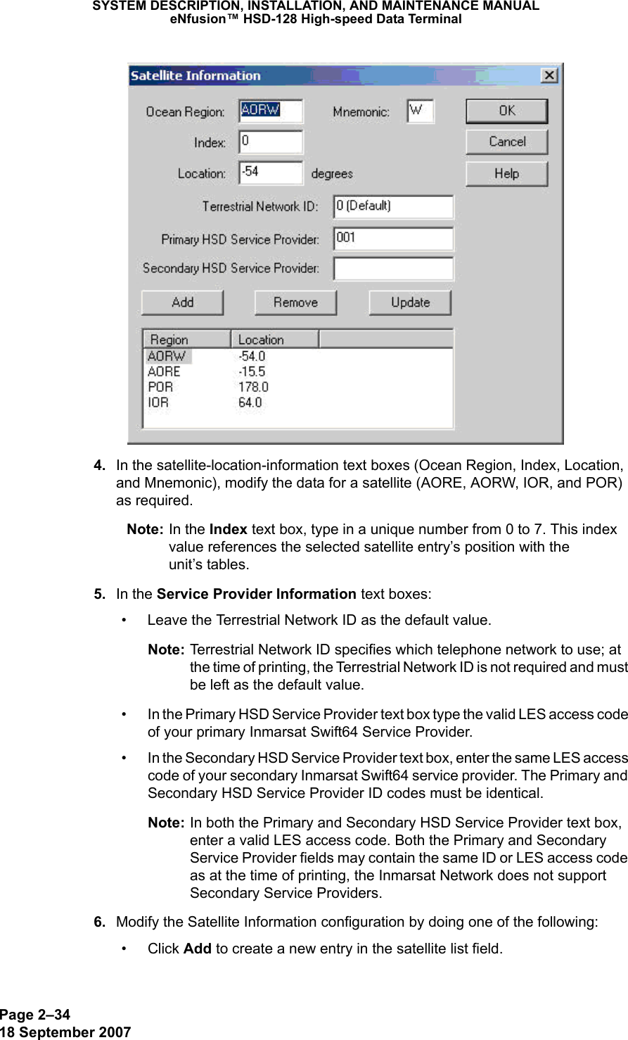
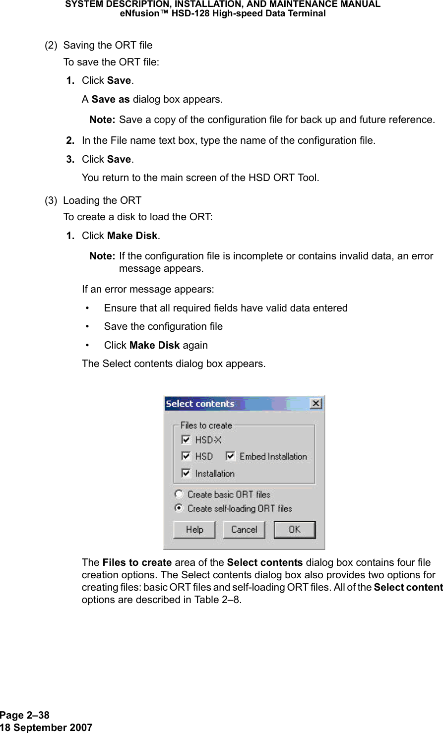
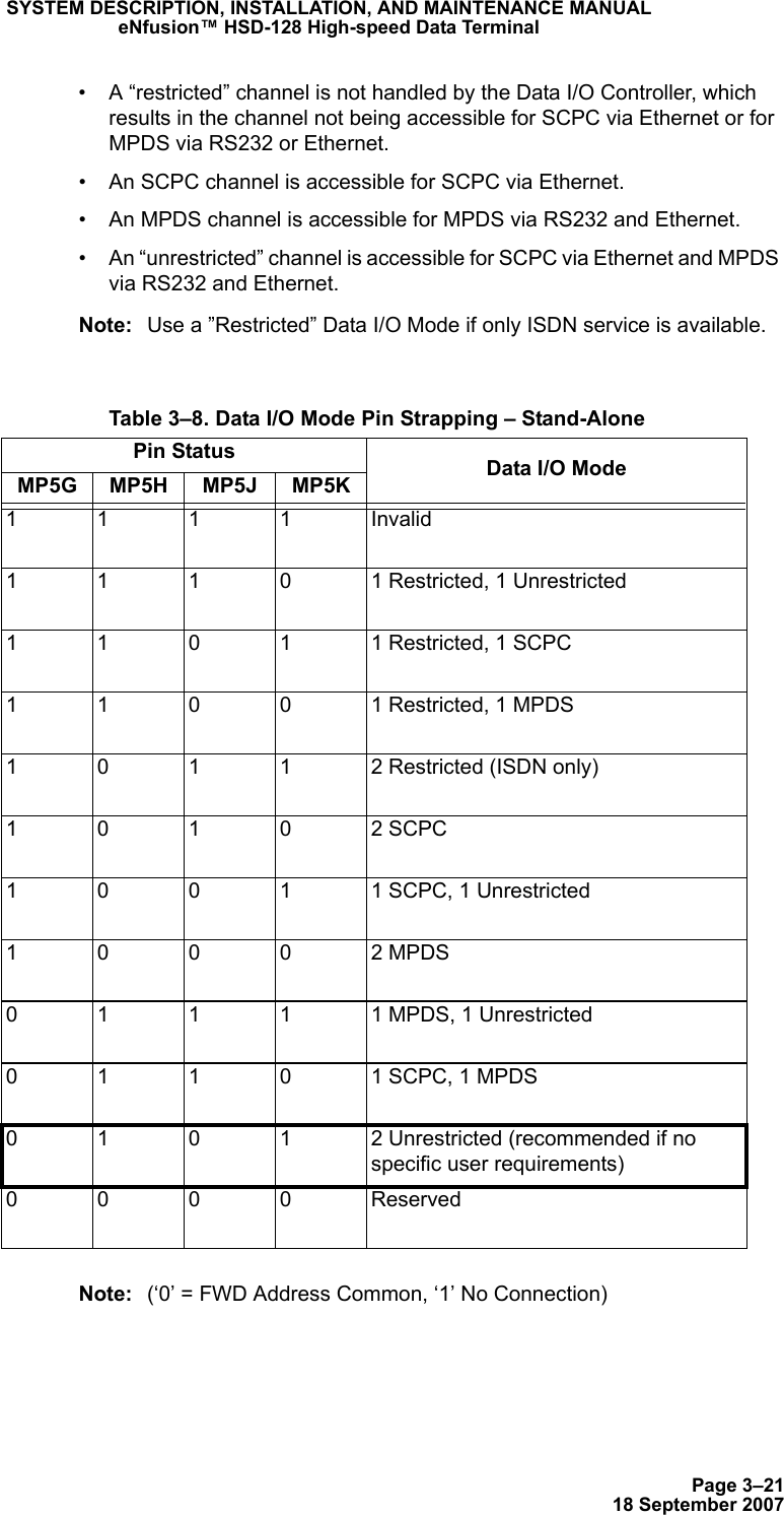
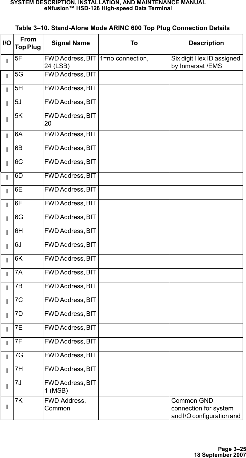
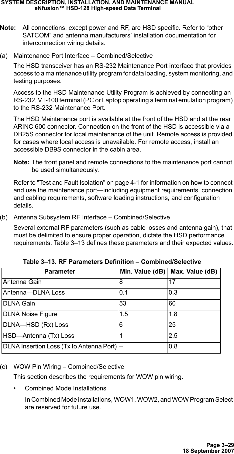
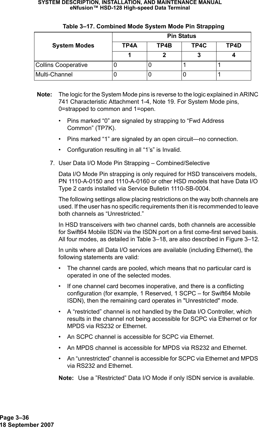
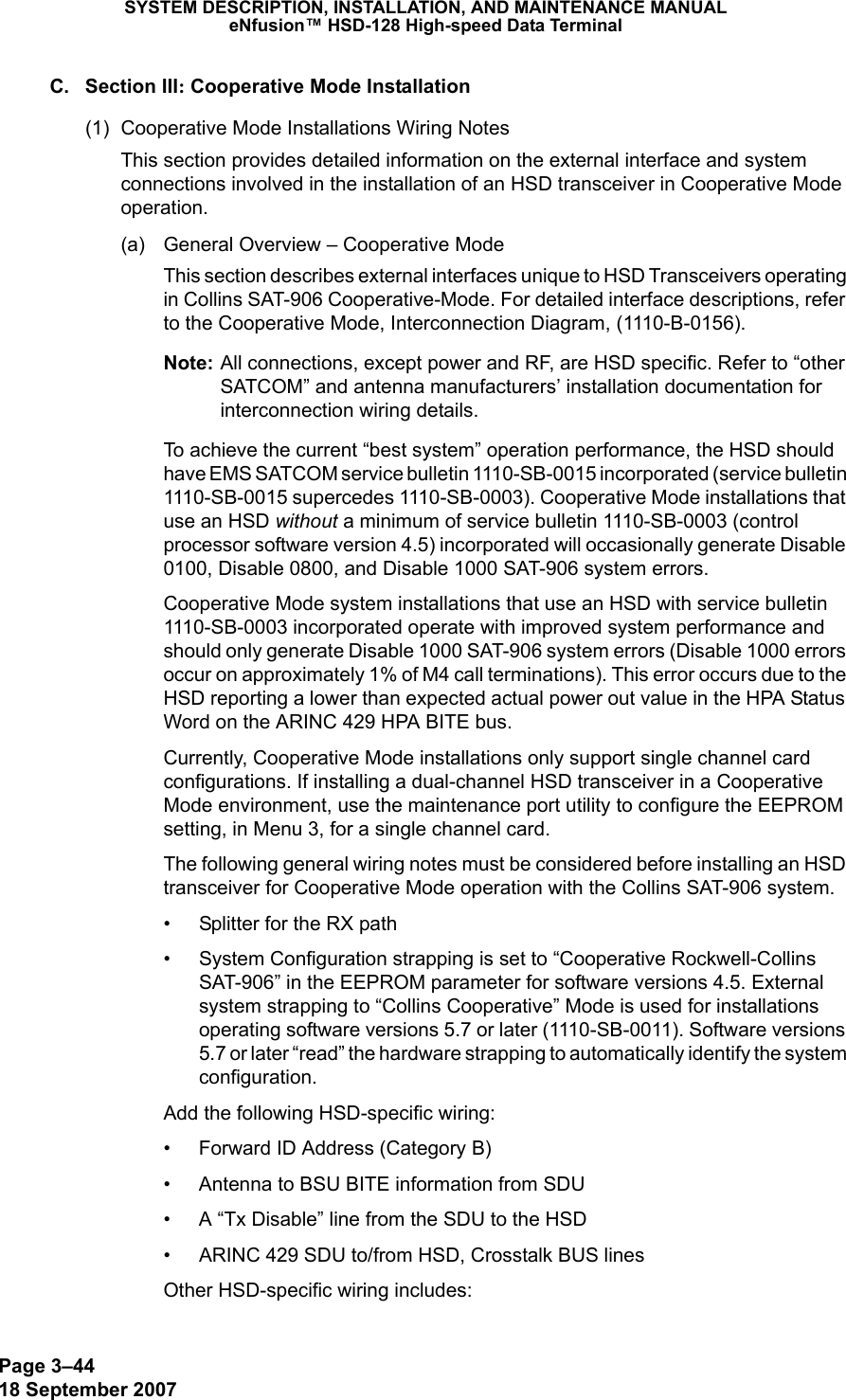
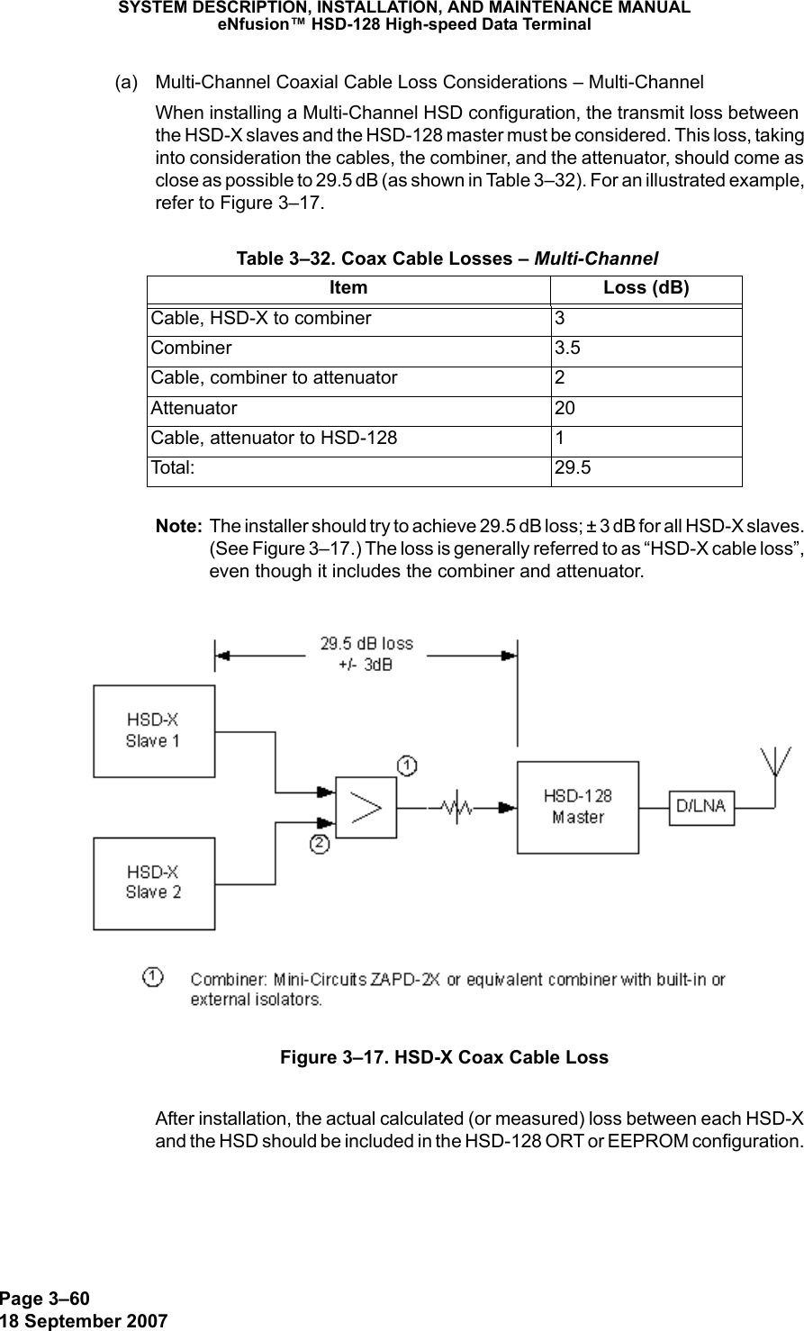
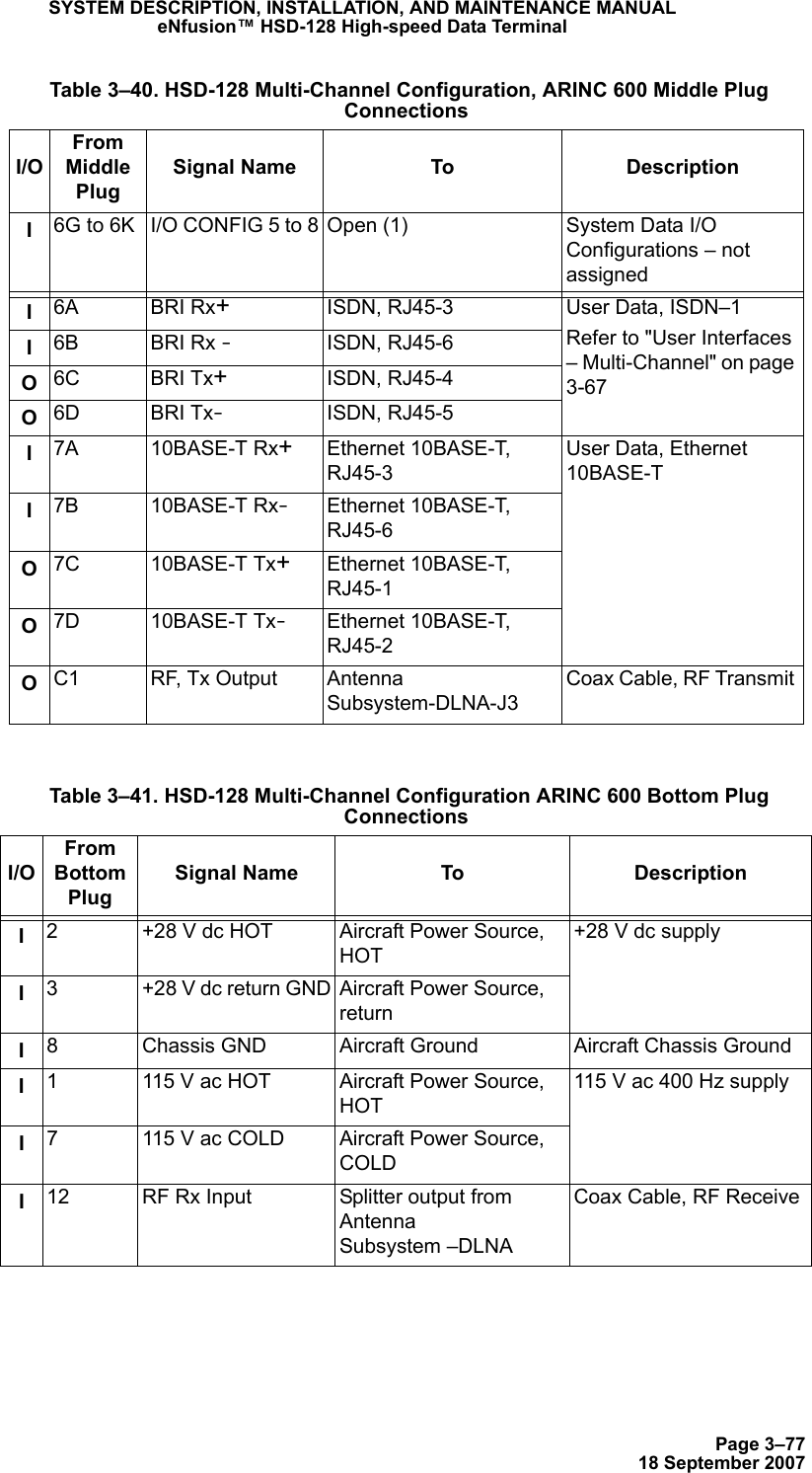
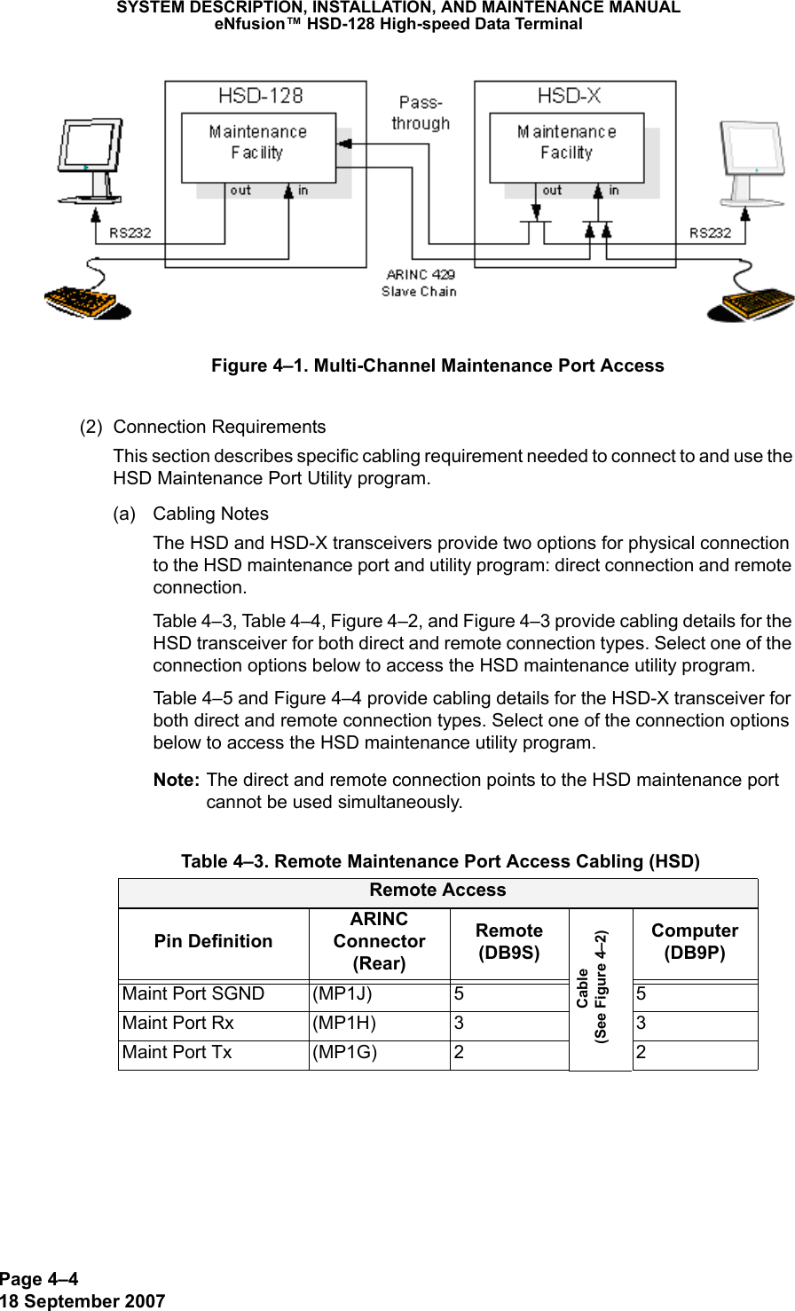
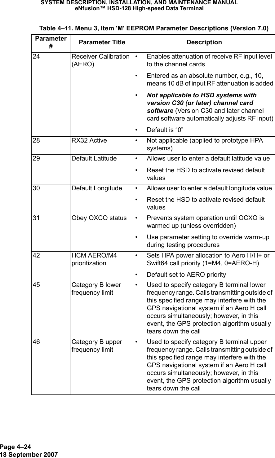
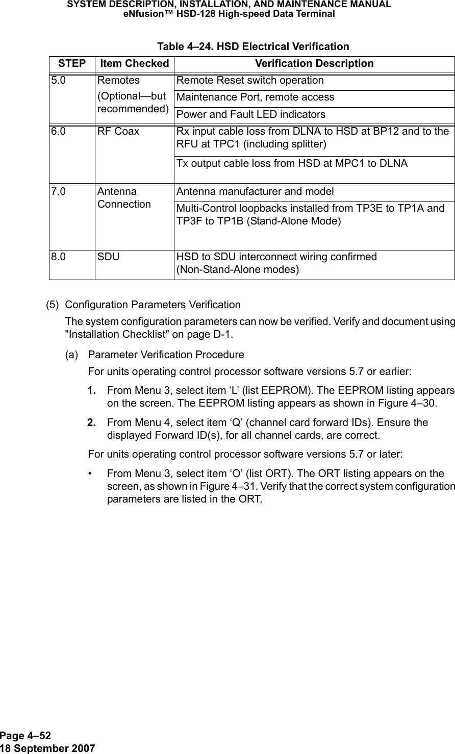
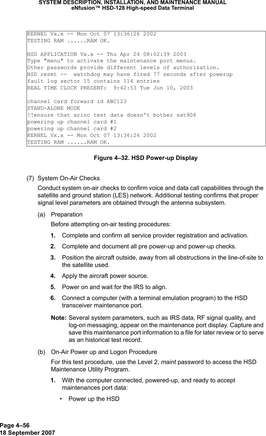
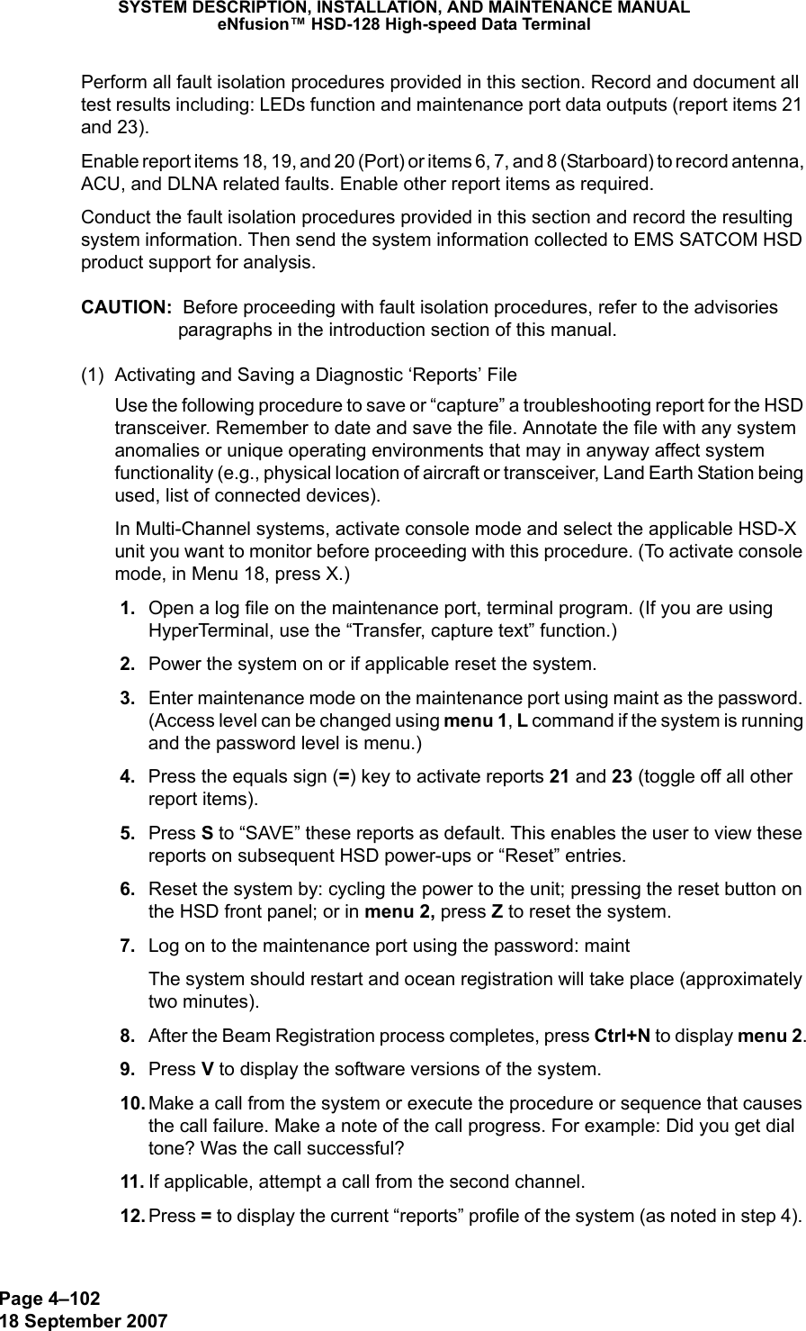
![Page 3–1318 September 2007SYSTEM DESCRIPTION, INSTALLATION, AND MAINTENANCE MANUALeNfusion™ HSD-128 High-speed Data TerminalAccess to the HSD Maintenance Utility Program is achieved by connecting an RS-232, VT-100 terminal (PC or Laptop operating a terminal emulation program) to the RS-232 Maintenance Port. The HSD Maintenance port is available at the front of the HSD and at the rear ARINC 600 connector. Connection on the front of the HSD is accessible via a DB25S connector for local maintenance of the unit. Remote access is provided for cases where local access is unavailable. For remote access, install an accessible DB9S connector in the cabin area.Note: The front panel and remote connections to the maintenance port cannot be used simultaneously.Refer to "Test and Fault Isolation" on page 4-1 for information on how to connect and use the maintenance port—including, equipment requirements, connection and cabling requirements, software loading instructions, and configuration details.(c) Antenna Subsystem RF Interface – Stand-AloneSeveral external RF parameters (such as cable losses and antenna gain), that must be delimited to ensure proper operation, dictate the HSD performance requirements. Table 3–3 defines these parameters and their expected values.(d) WOW Pin Wiring – Stand-AloneThese Weight-On-Wheel (WOW) discretes are wired only if equivalent information is not strapped as being available to the SDU on an ARINC 429 input [for example, IRS or the Centralized Fault Display System (CFDS)].WOW wiring, for the HSD, is optional for system operation as the HSD already receives speed information for Doppler correction. However, if WOW wiring is not wired, normal maintenance must be disabled when speed or Doppler readings are greater than zero.The WOW1 and WOW2 pins are either left open circuit or they are connected to the airframe DC ground. The WOW Program Select (PGM) pin is either left open circuit or is connected to the Forward Address Common. The three ground states, defined for any pin are:• OPN: Open circuit Table 3–3. RF Parameters DefinitionParameter Min. Value (dB) Max. Value (dB)Antenna Gain 8 17Antenna—DLNA Loss 0.1 0.3DLNA Gain 53 60DLNA Noise Figure 1.5 1.8DLNA—HSD (Rx) Loss 6 25HSD—Antenna (Tx) Loss 1 2.5DLNA Insertion Loss (Tx to Antenna Port)–0.8](https://usermanual.wiki/EMS-Technologies-Canada/HSD-X/User-Guide-1275806-Page-153.png)
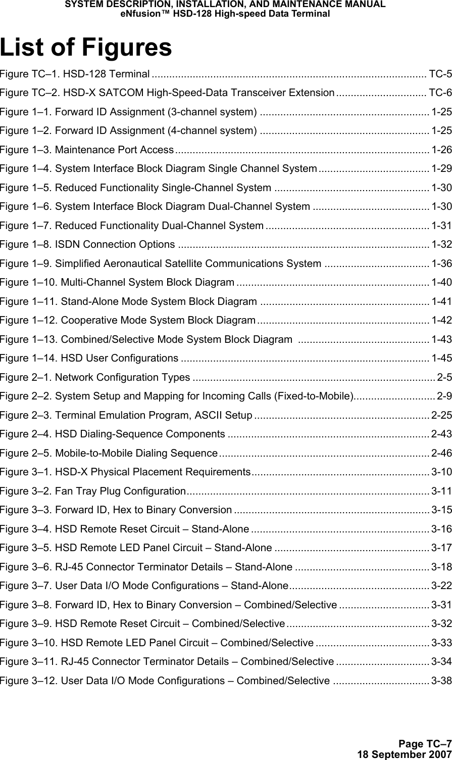
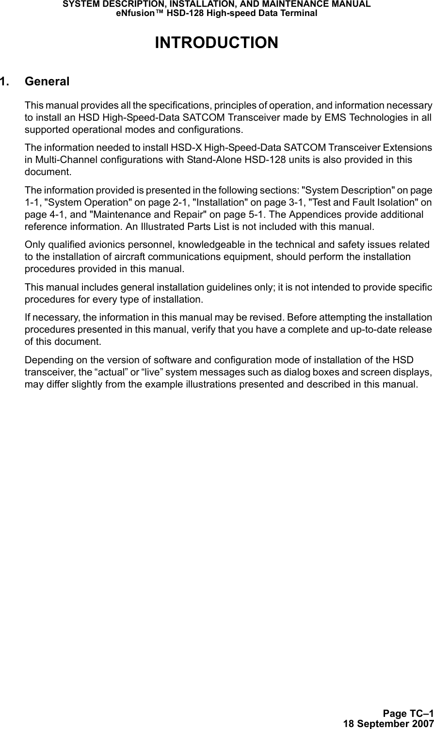
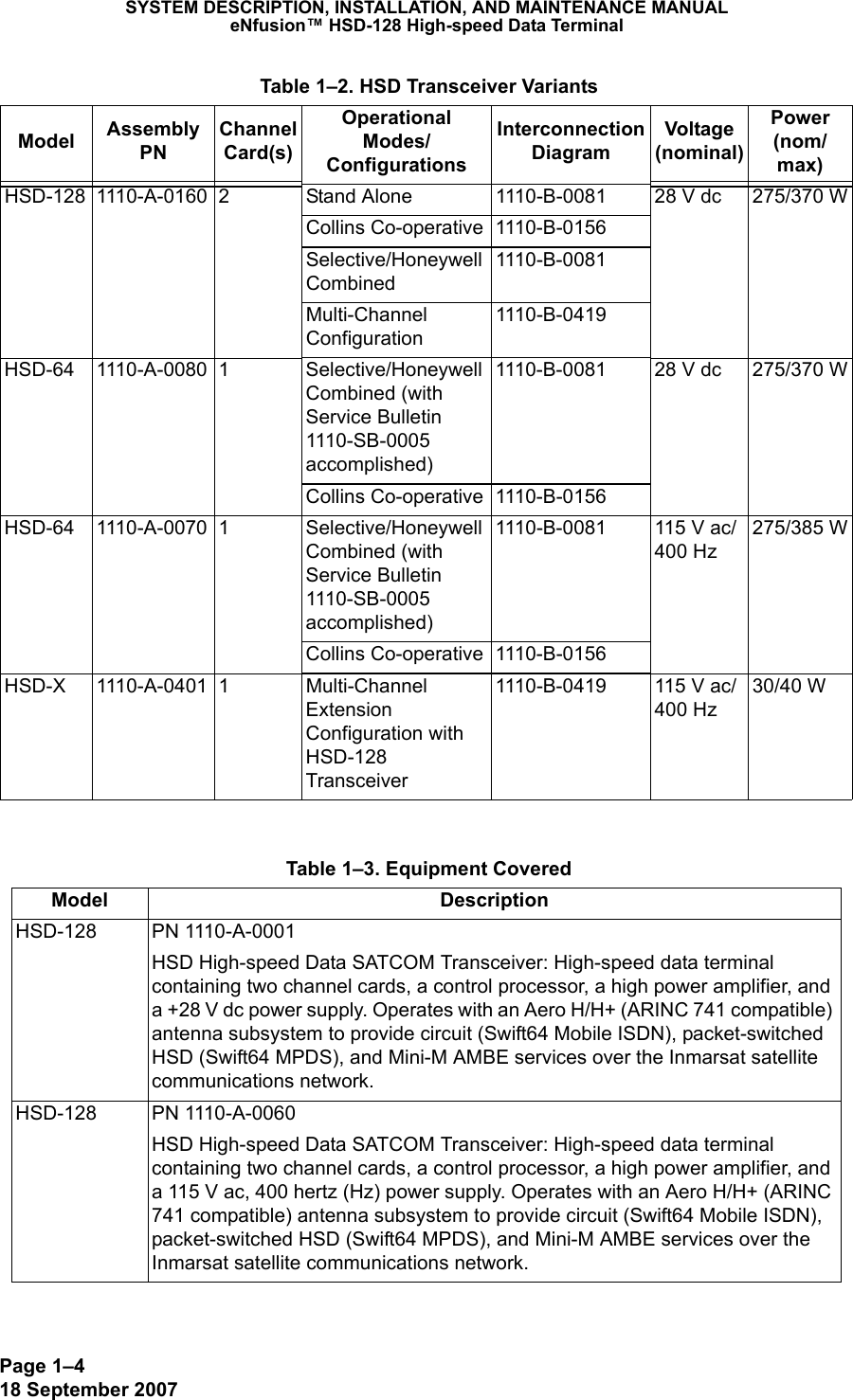
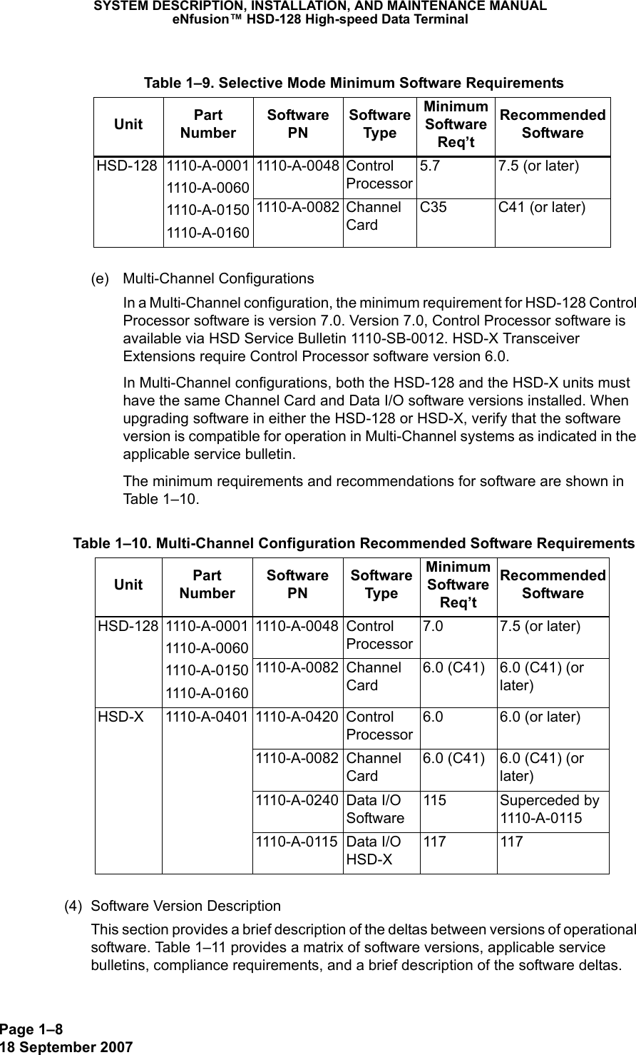
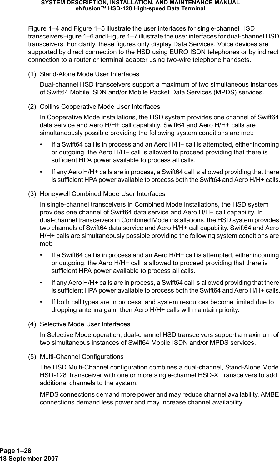
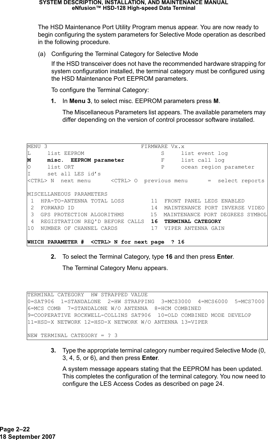
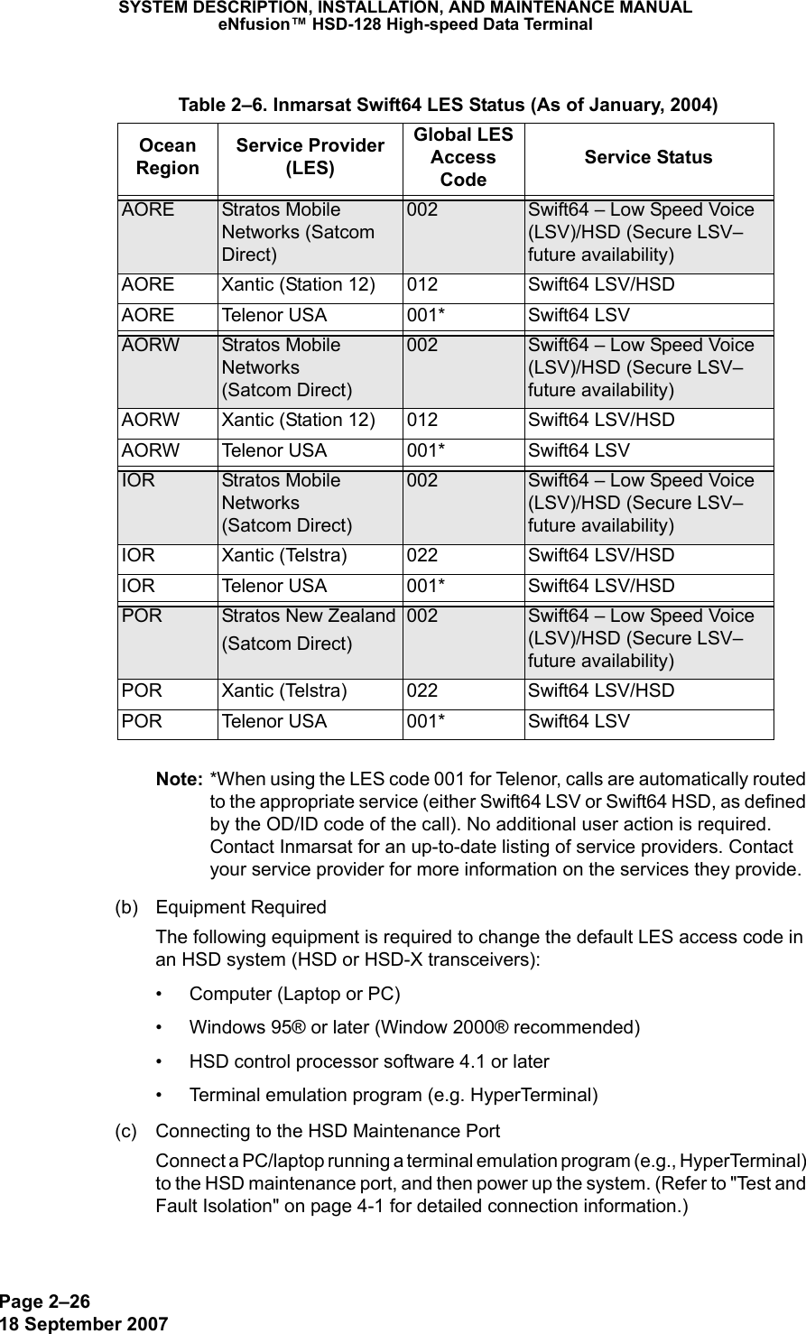
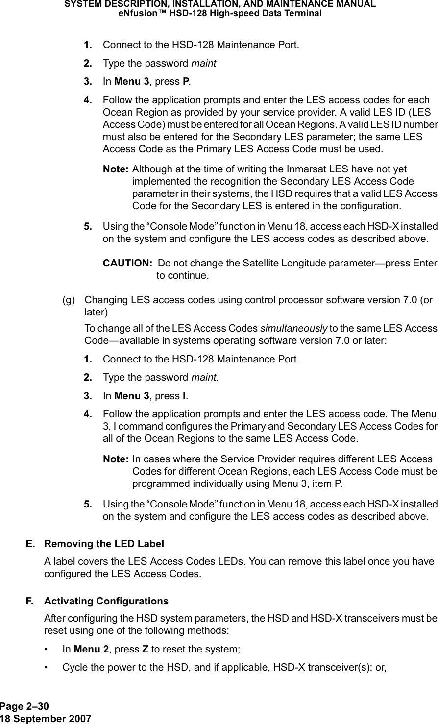
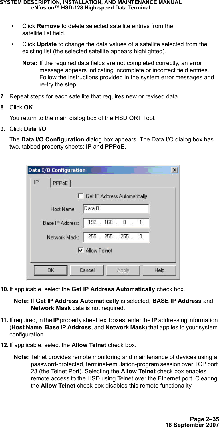
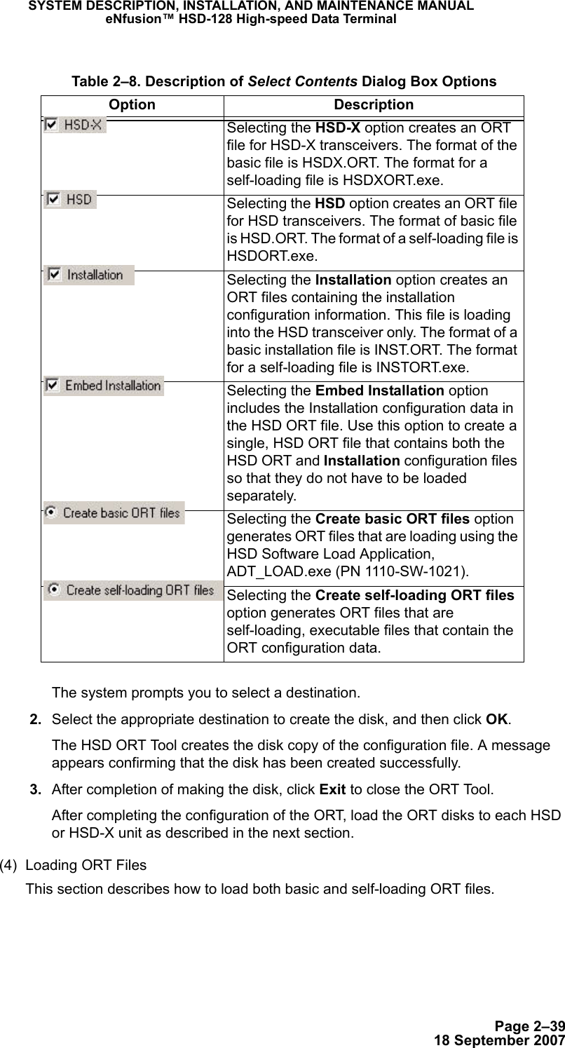
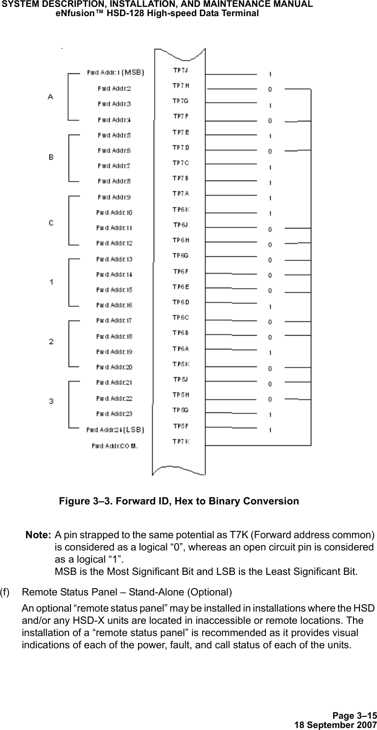
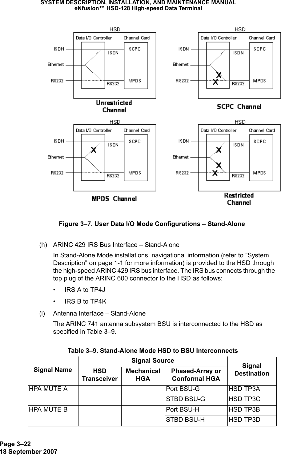
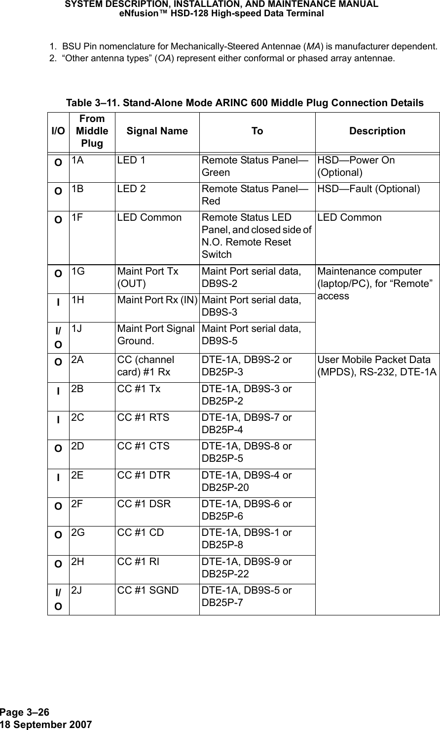
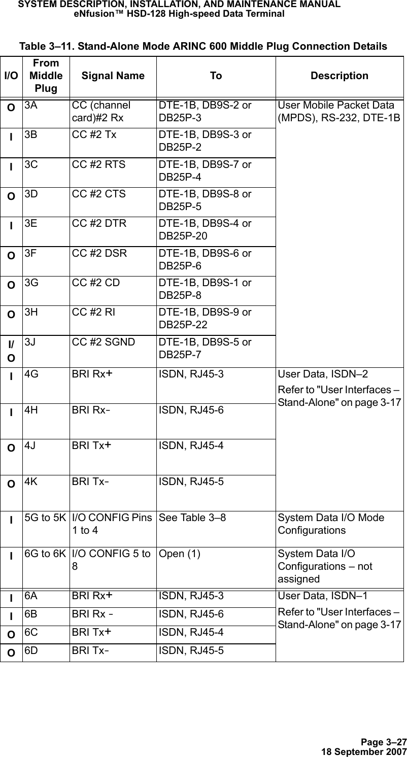
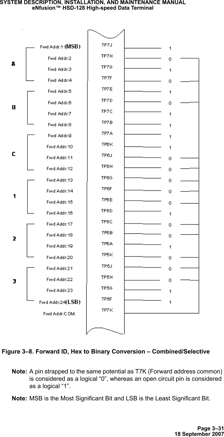
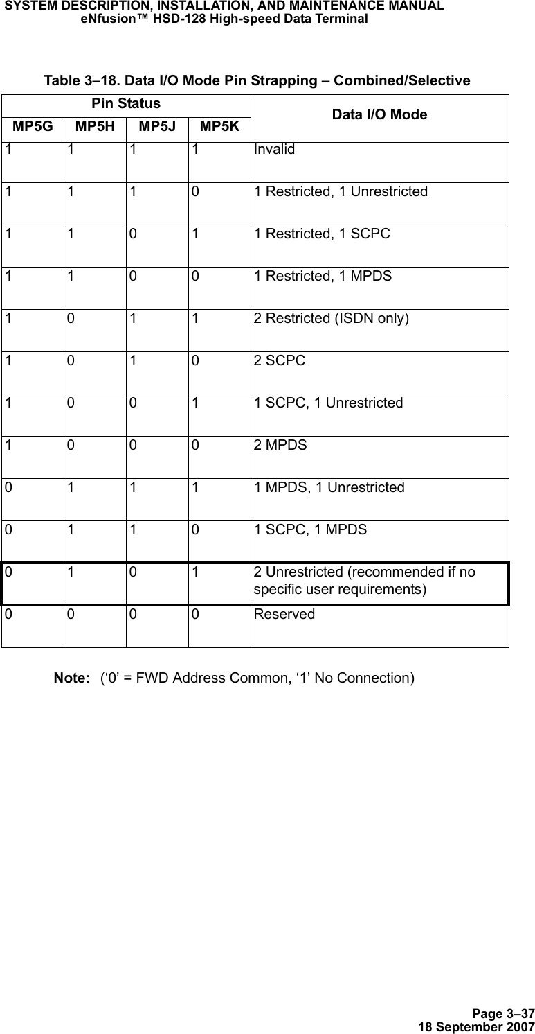
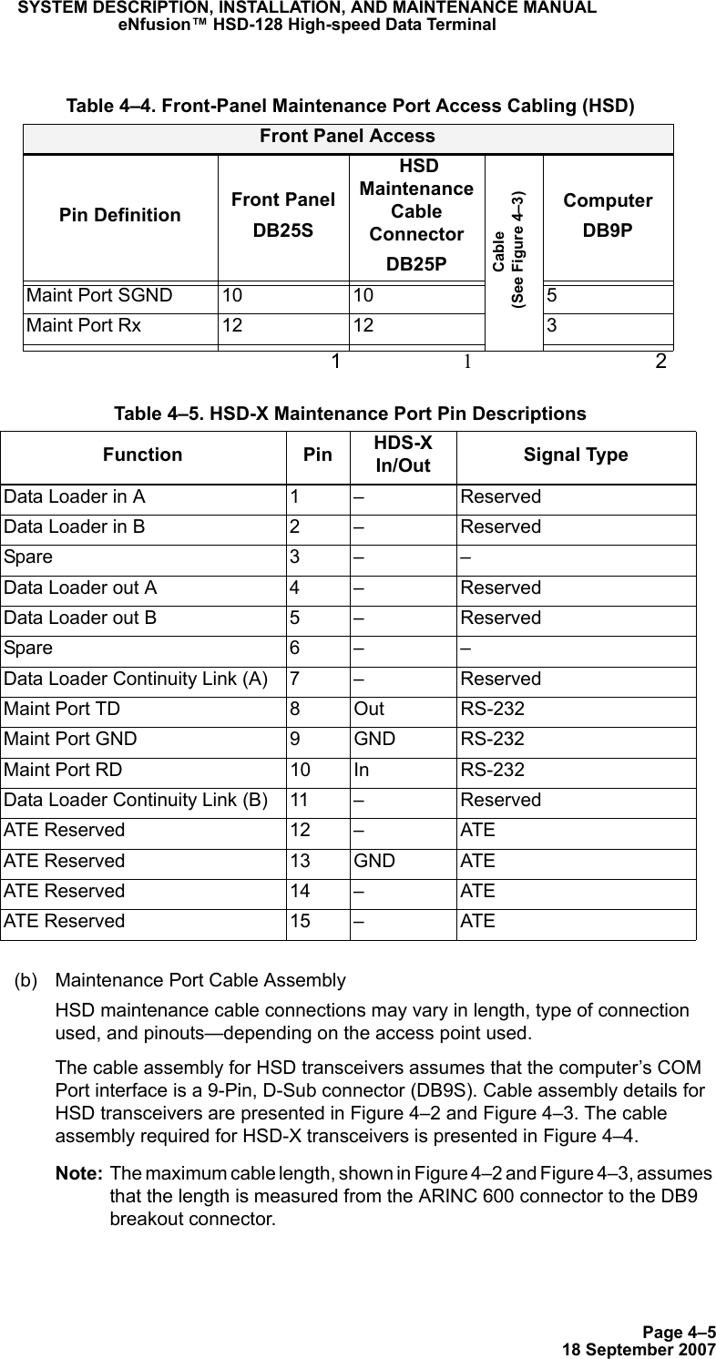
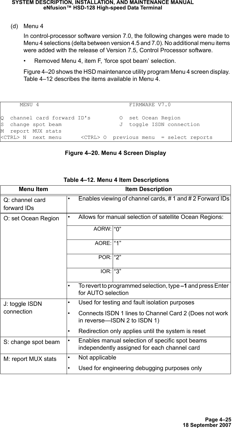
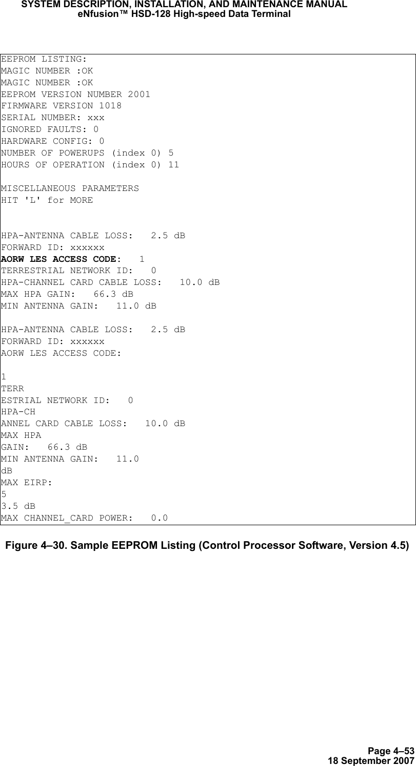
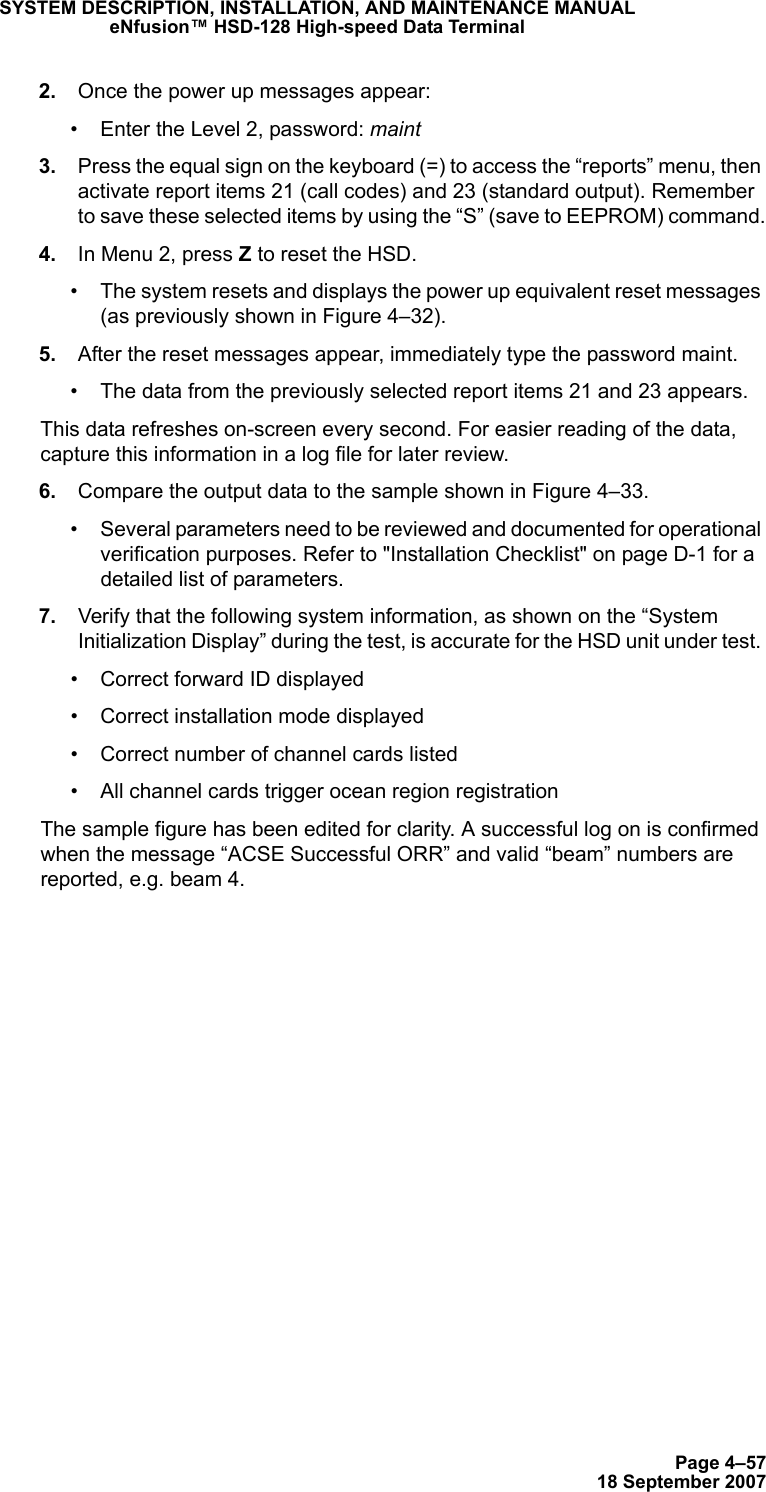
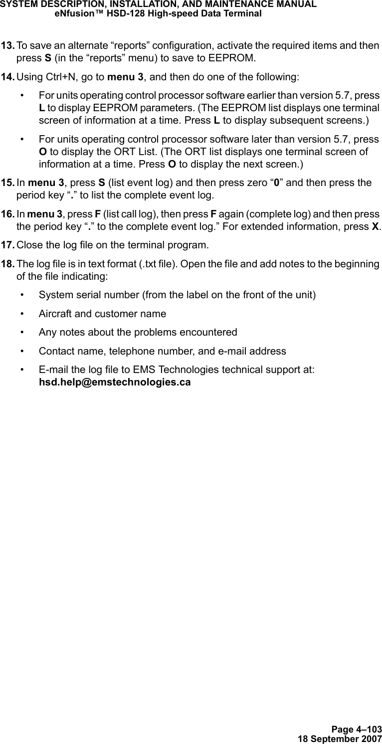
![Page 3–1418 September 2007SYSTEM DESCRIPTION, INSTALLATION, AND MAINTENANCE MANUALeNfusion™ HSD-128 High-speed Data Terminal• AFG: Airframe DC Ground• FAC: Fwd Address Common (TP7K)Resolve any conflict between WOW1 and WOW2 by assuming the aircraft is “in-air.” The interpretation of the state of the WOW1 and WOW2 pins is defined by the state of the WOW program select pin. Refer to Table 3–4 for details.1. Stand-Alone Mode InstallationsLabeled as WOW1, WOW2, and WOW Program Select, these discretes are wired only if equivalent information is not strapped as being available to the SDU on an ARINC 429 input [for example, IRS or the Centralized Fault Display System (CFDS)].WOW wiring is optional for system operation in Stand-Alone Mode installations as the HSD already receives speed information for Doppler correction. However, if WOW wiring is not wired, normal maintenance must be disabled when speed or Doppler readings are greater than zero.(e) Forward and Return Address IDs – Stand-AloneFigure 3–3 provides an example of a Forward ID address. The Forward ID is a Hex number (example: $ABC123) that must be converted into a binary number for strapping. Table 3–4. WOW Pin Wiring TablePin Name and LocationWOW1 WOW2 PGM Aircraft StatusTP3G TP3H TP3JAFG AFG FAC In-airOPN AFG FAC Not valid – Default in-airAFG OPN FAC Not valid – Default in-airOPN OPN FAC On-groundAFG AFG OPN On-groundOPN AFG OPN Not valid – Default in-airAFG OPN OPN Not valid – Default in-airOPN OPN OPN In-air](https://usermanual.wiki/EMS-Technologies-Canada/HSD-X/User-Guide-1275806-Page-154.png)
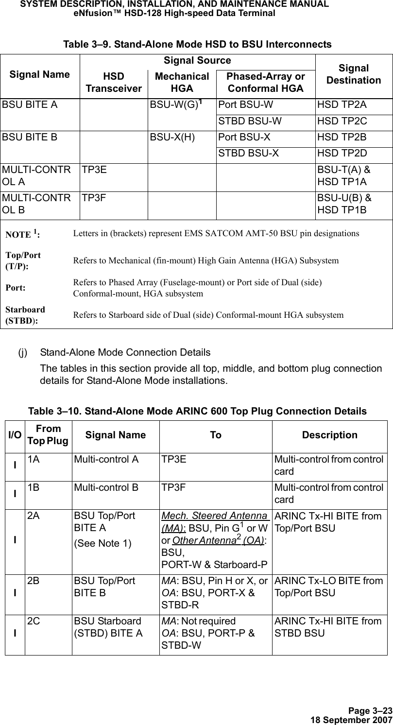
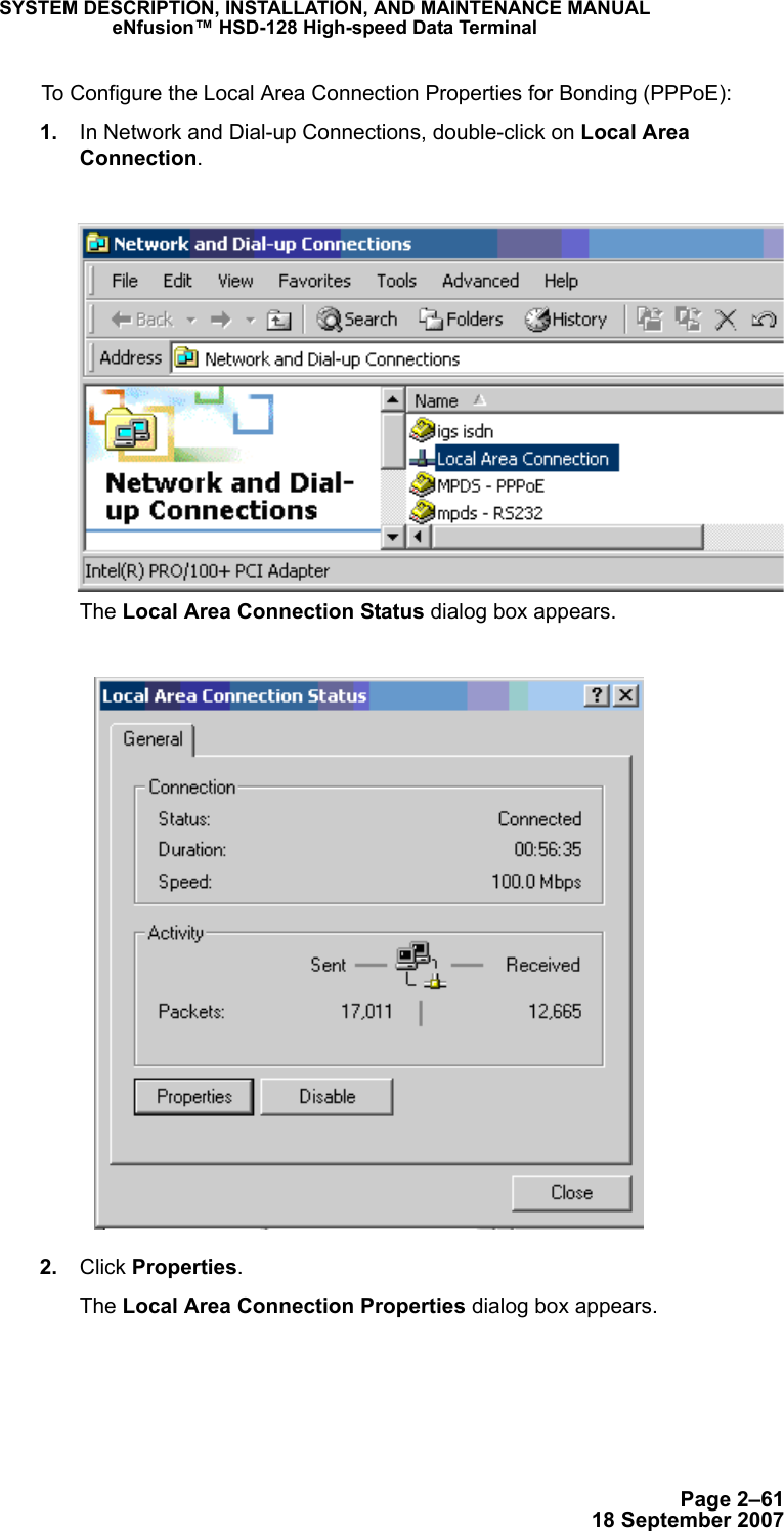
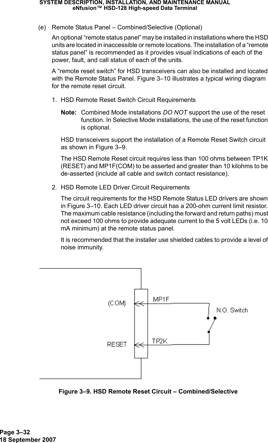
![Page 3–3018 September 2007SYSTEM DESCRIPTION, INSTALLATION, AND MAINTENANCE MANUALeNfusion™ HSD-128 High-speed Data Terminal• Selective Mode InstallationsLabeled as WOW1, WOW2, and WOW Program Select, these discretes are wired only if equivalent information is not strapped as being available to the SDU on an ARINC 429 input [for example, IRS or the Centralized Fault Display System (CFDS)].WOW wiring is optional for system operation in Selective Mode installations as the HSD already receives speed information for Doppler correction. However, if WOW wiring is not wired, normal maintenance must be disabled when speed or Doppler readings are greater than zero.(d) Forward and Return Address IDs – Combined/SelectiveFigure 3–8 provides an example of a Forward ID address. The Forward ID is a Hex number (example: $ABC123) that must be converted into a binary number for strapping. Table 3–14. WOW Pin Wiring Table – Combined/SelectivePin Name and LocationWOW1 WOW2 PGM Aircraft StatusTP3G TP3H TP3JAFG AFG FAC In-airOPN AFG FAC Not valid – Default in-airAFG OPN FAC Not valid – Default in-airOPN OPN FAC On-groundAFG AFG OPN On-groundOPN AFG OPN Not valid – Default in-airAFG OPN OPN Not valid – Default in-airOPN OPN OPN In-air](https://usermanual.wiki/EMS-Technologies-Canada/HSD-X/User-Guide-1275806-Page-170.png)
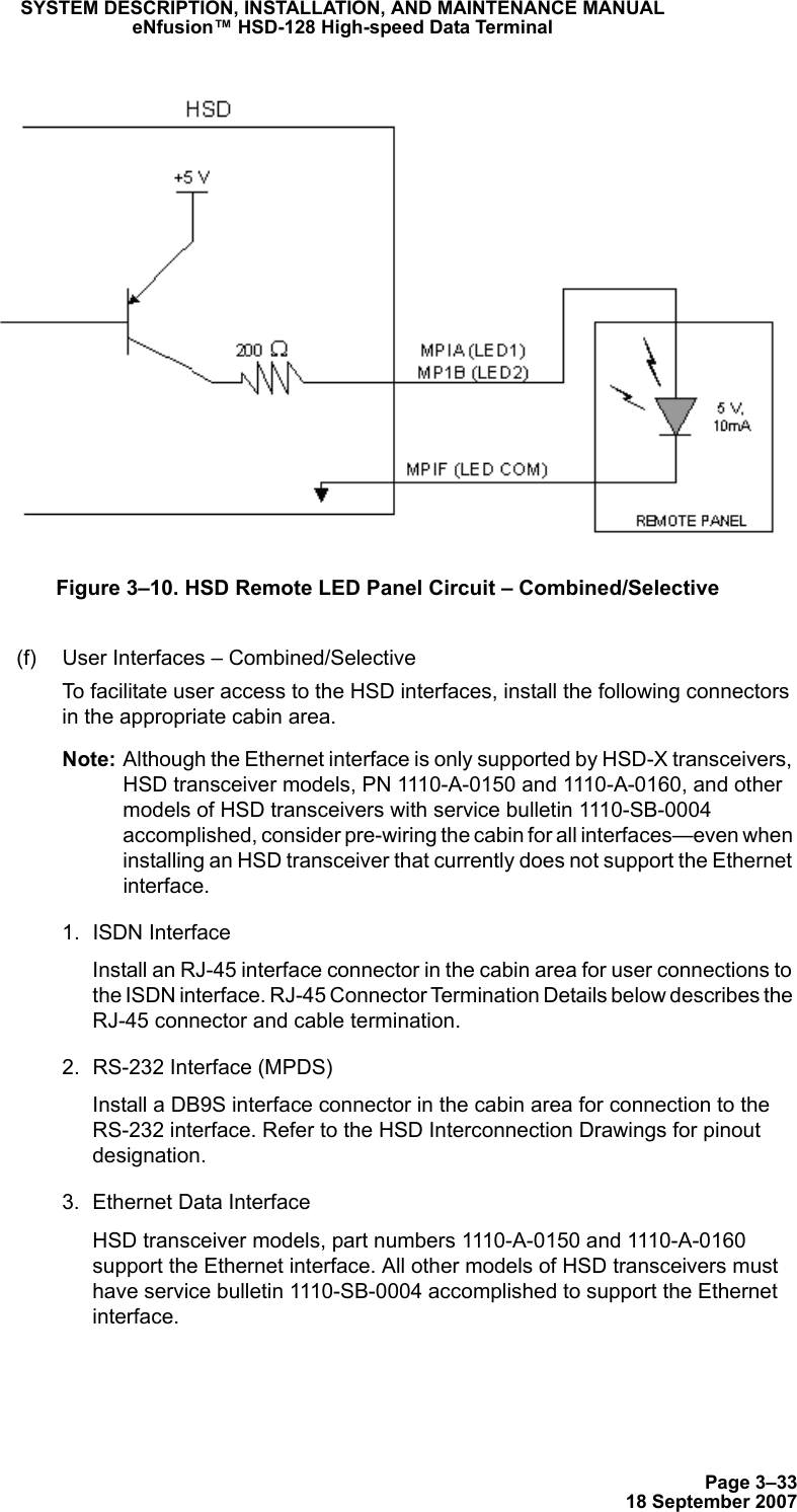
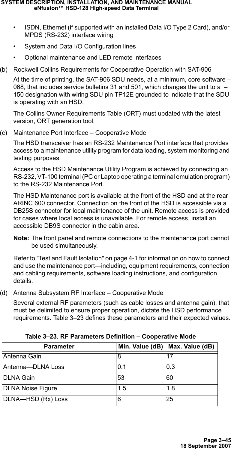
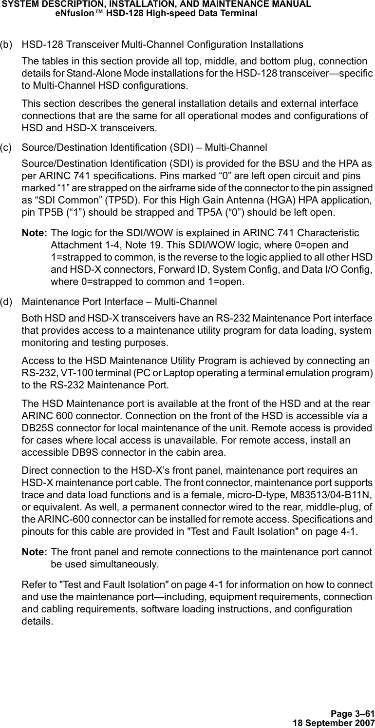
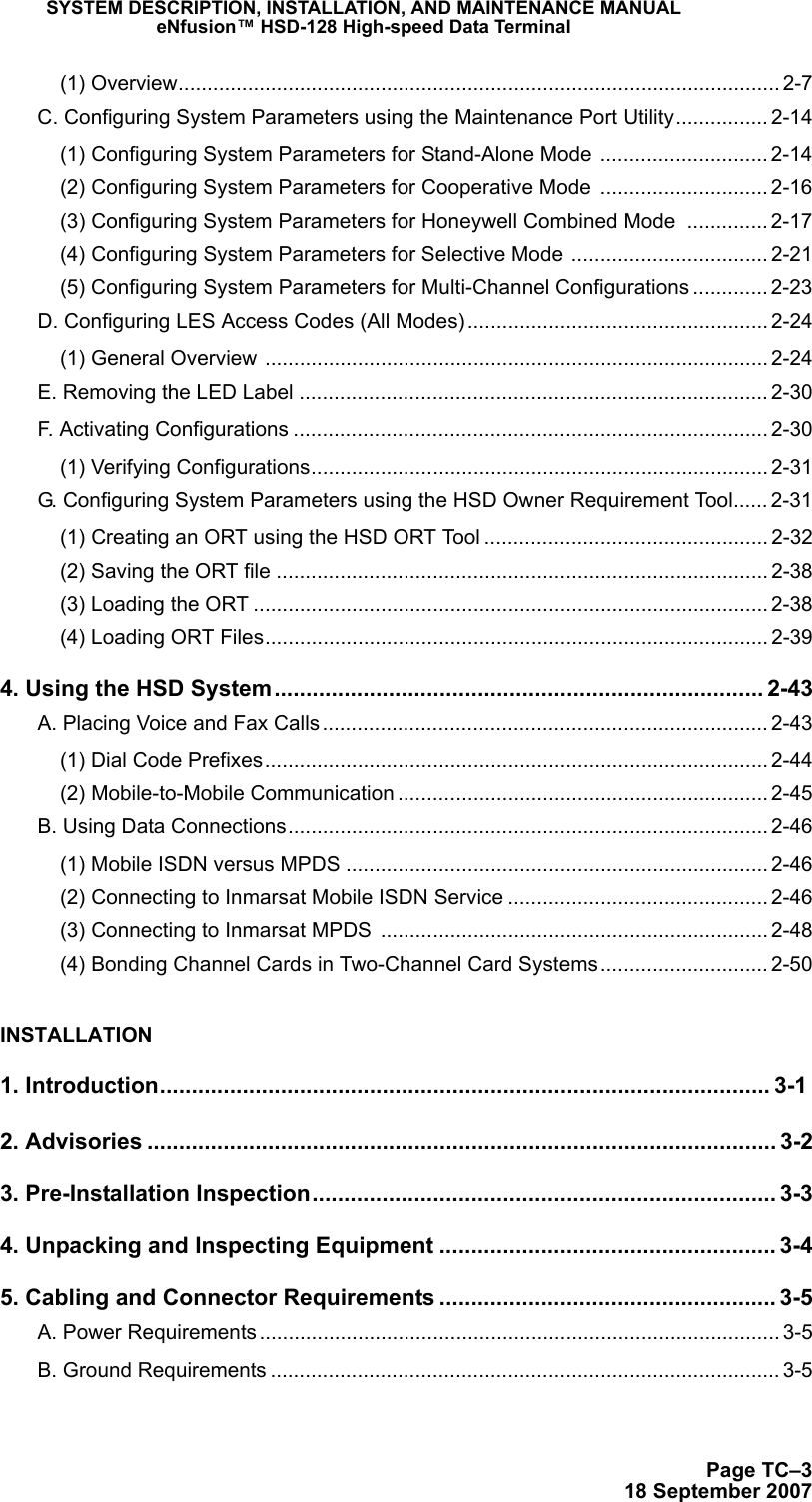
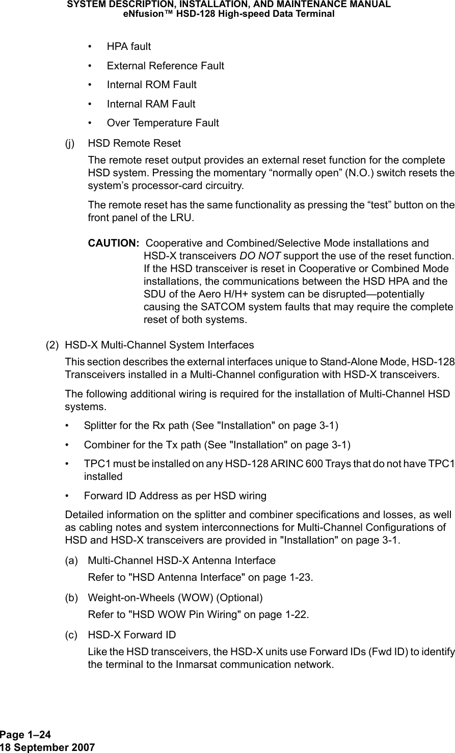
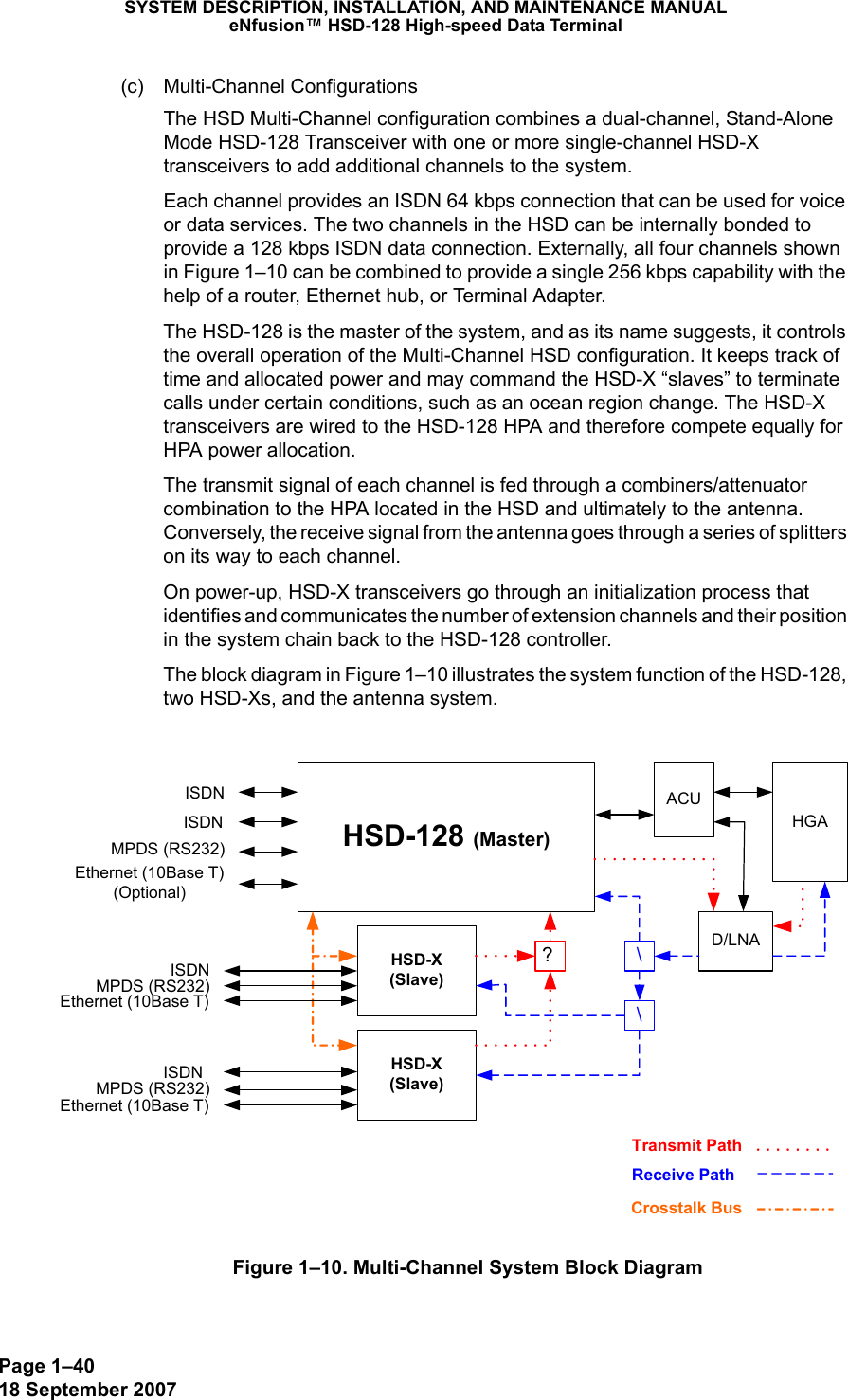
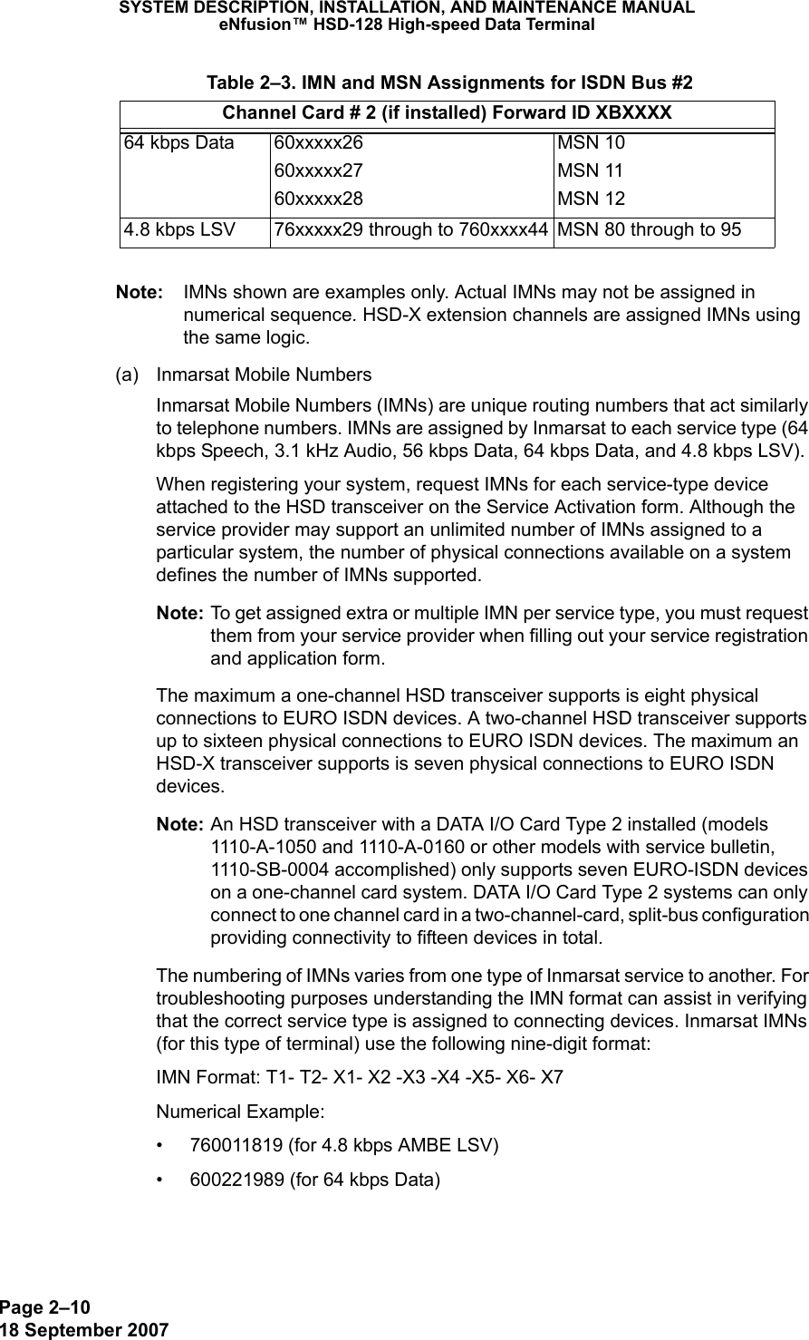
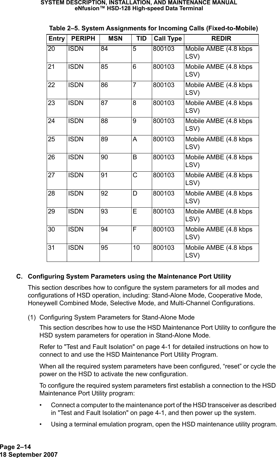
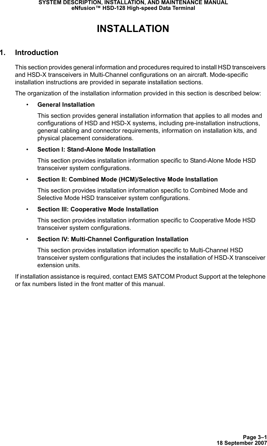
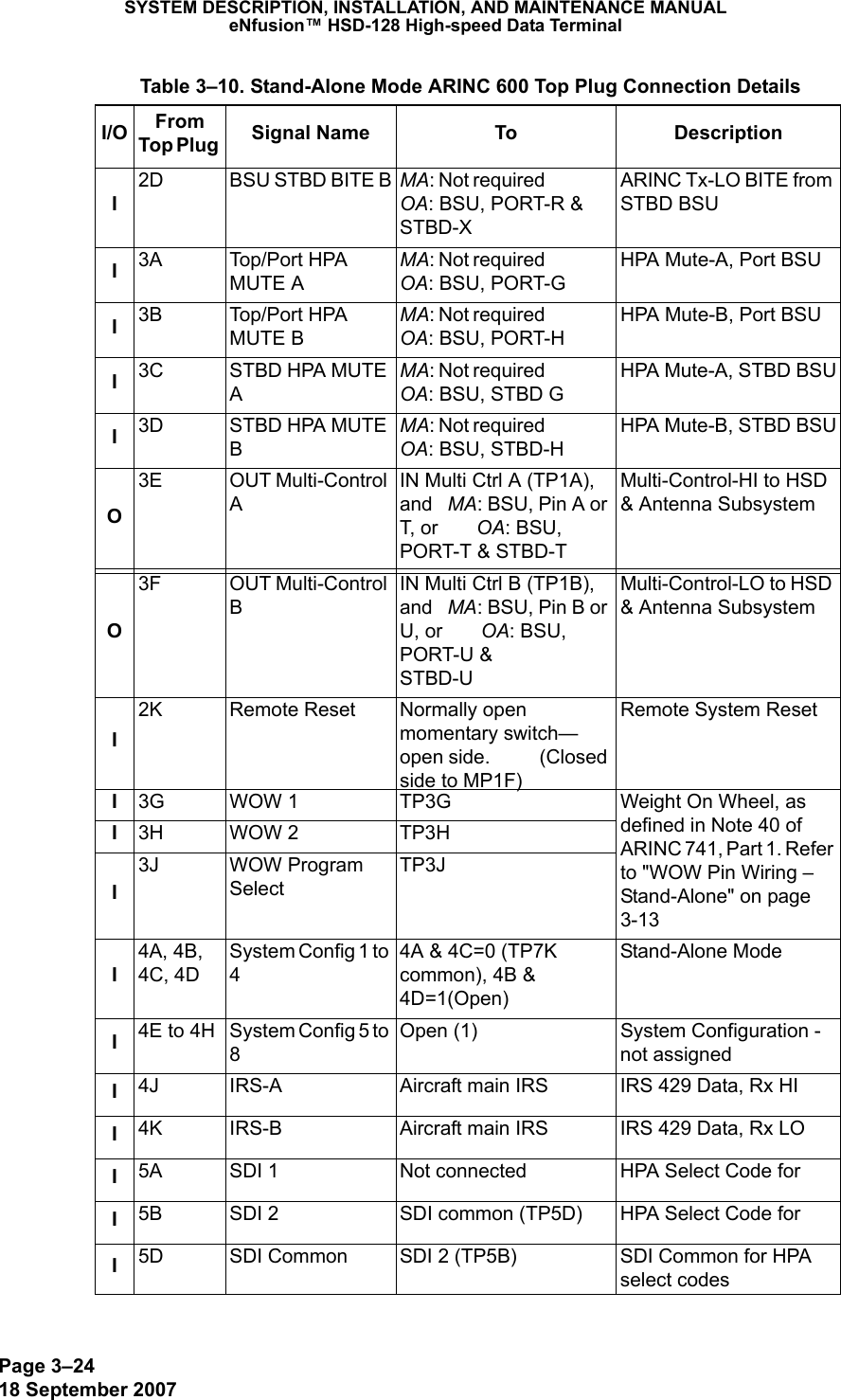
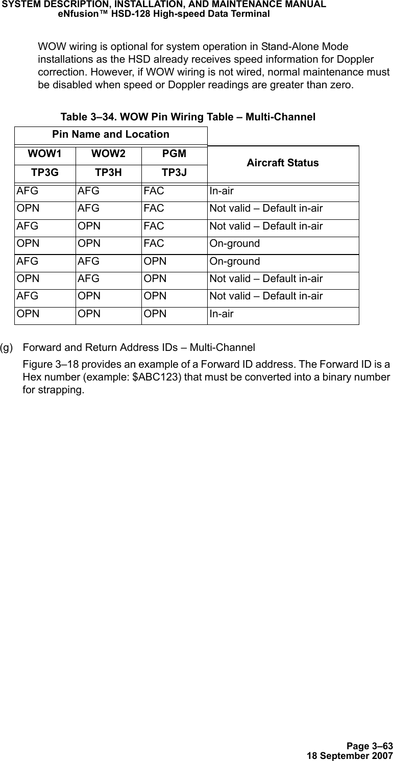
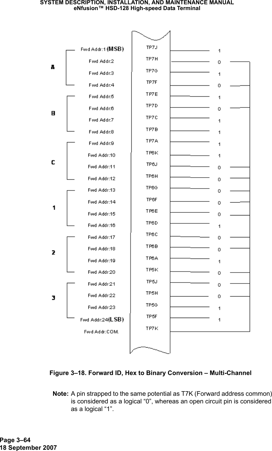
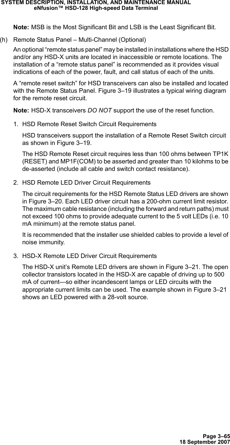
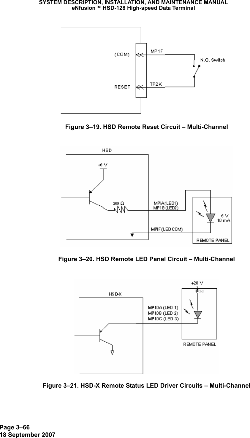
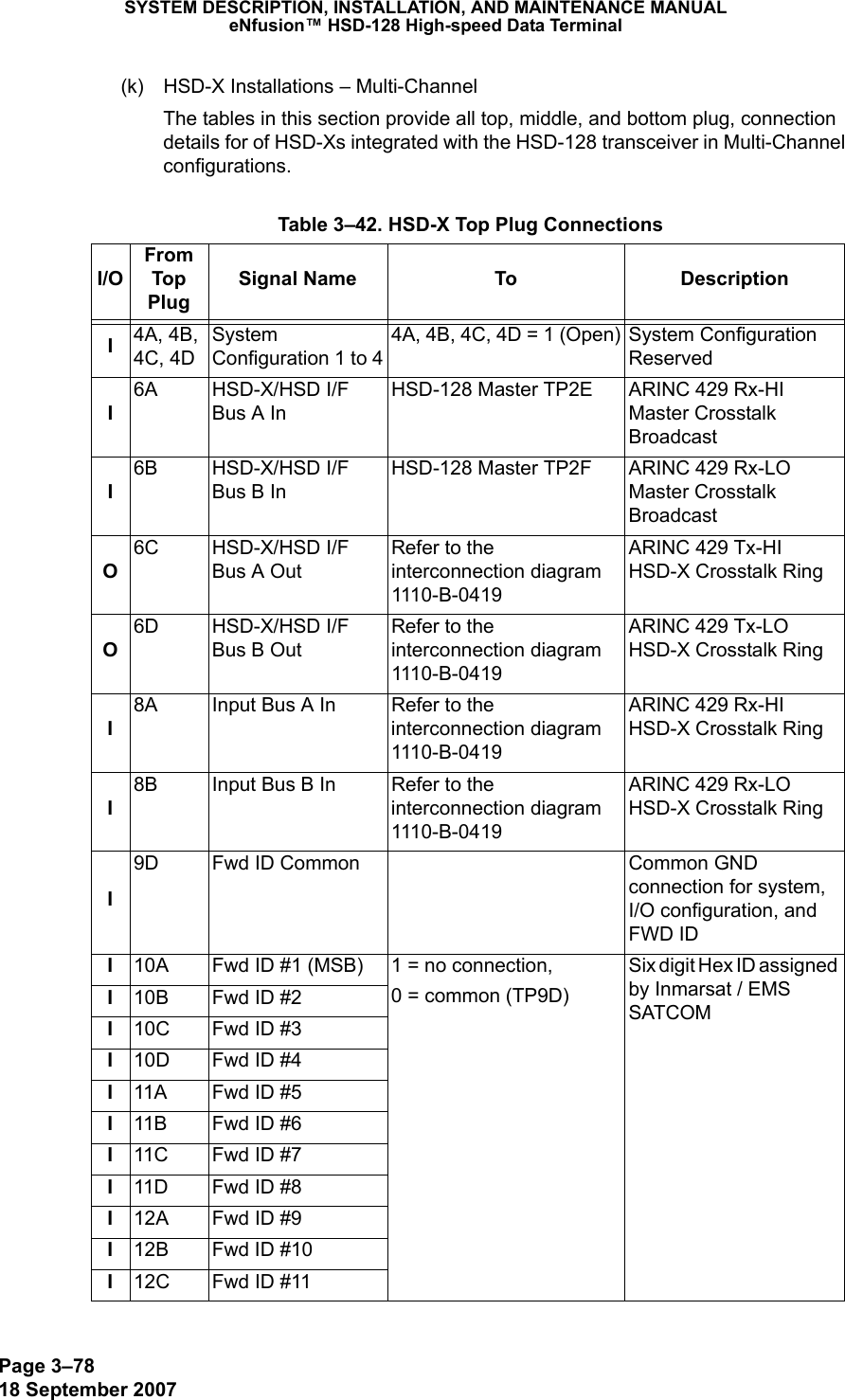
![Page 3–6218 September 2007SYSTEM DESCRIPTION, INSTALLATION, AND MAINTENANCE MANUALeNfusion™ HSD-128 High-speed Data Terminal(e) Antenna Subsystem RF Interface – Multi-ChannelSeveral external RF parameters (such as cable losses and antenna gain), that must be delimited to ensure proper operation, dictate the HSD performance requirements. Table 3–33 defines these parameters and their expected values.(f) WOW Pin Wiring – Multi-ChannelThese Weight-On-Wheel (WOW) discretes are wired only if equivalent information is not strapped as being available to the SDU on an ARINC 429 input [for example, IRS or the Centralized Fault Display System (CFDS)].WOW wiring, for the HSD, is optional for system operation as the HSD already receives speed information for Doppler correction. However, if WOW wiring is not wired, normal maintenance must be disabled when speed or Doppler readings are greater than zero.The WOW1 and WOW2 pins are either left open circuit or they are connected to the airframe DC ground. The WOW Program Select (PGM) pin is either left open circuit or is connected to the Forward Address Common. The three ground states, defined for any pin are:• OPN: Open circuit• AFG: Airframe DC Ground• FAC: Fwd Address Common (TP7K)Resolve any conflict between WOW1 and WOW2 by assuming the aircraft is “in-air.” The interpretation of the state of the WOW1 and WOW2 pins is defined by the state of the WOW program select pin. Refer to Table 3–34 for details.1. Multi-Channel ConfigurationsLabeled as WOW1, WOW2, and WOW Program Select, these discretes are wired only if equivalent information is not strapped as being available to the SDU on an ARINC 429 input [for example, IRS or the Centralized Fault Display System (CFDS)]. Table 3–33. RF Parameters Definition – Multi-ChannelParameter Min. Value (dB) Max. Value (dB)Antenna Gain 8 17Antenna—DLNA Loss 0.1 0.3DLNA Gain 53 60DLNA Noise Figure 1.5 1.8DLNA—HSD-128 (BP12), including cables and splitter (Rx) Total Loss019DLNA—HSD-X (BP5), including cables and splitter (Rx) Total Loss524HSD-128—Antenna (Tx) Loss 1 2.5DLNA Insertion Loss (Tx to Antenna Port)–0.8](https://usermanual.wiki/EMS-Technologies-Canada/HSD-X/User-Guide-1275806-Page-202.png)

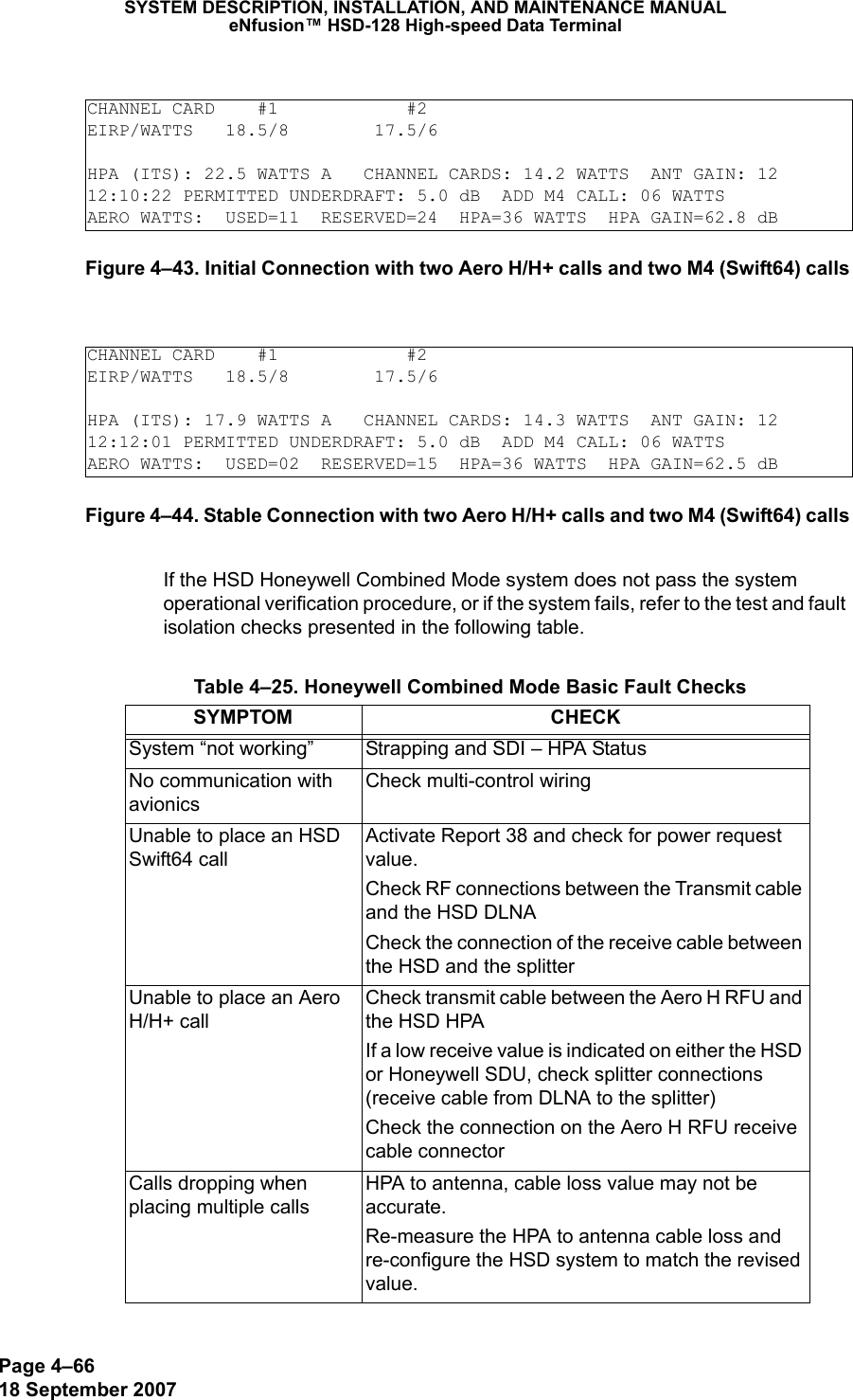
![Page 4–7318 September 2007SYSTEM DESCRIPTION, INSTALLATION, AND MAINTENANCE MANUALeNfusion™ HSD-128 High-speed Data TerminalThis completes the first load of the Channel Card software selected in step 10. 14. For HSD transceivers with two channel cards, repeat all required software loads to both channel cards. 15. Repeat steps 7 through 13 for all other required software loads of Channel Card Software files as specified in the applicable software service bulletin. 16. When all Channel Card Software is loaded, reset or cycle the power on the HSD transceiver. 17. If no other software loads are required, proceed to "Verifying Software Loads" on page 4-78. 18. In the event that the load fails, restart the load from the beginning of the Loading Channel Card Software procedure. If after two attempts the load still does not complete successfully, assume that the software disks or files may have been corrupted or the software is incompatible with the hardware configuration. Contact EMS SATCOM product support for assistance. (2) Loading Control Processor Software CAUTION: When loading software to the units in installation environments that include an SDU, disable the SDU (Power off or remove the sdu from the arinc tray) before beginning the software load procedure.HSD/HST LOADER Vx.x -- Mon Mar 24 12:12:17 2003which target ? 0 = control processor 1 = channel card #1 2 = channel card #2 3 = HPA application 4 = data i/o card 5 = HPA application with manual setup 6 = HPA application plus boot with manual setup 7 = HPA application plus boot 8 = channel card #1 boot code 9 = channel card #2 boot code 11 = channel card #1 pic code 12 = channel card #2 pic code 13 = HCM application 14 = HST ORT 15 = HSD ORT 16 = HSD-X ORT?1 File name, which contains the firmware image? applxx.hexThis download will require one of the PC's COM ports. (1, 2, etc) [1] ?1Connect COM1 of this PC to the maintenance port of the data terminal.Hit <ESC> to abort, or <Enter> to proceedEstablishing communication to the data terminal -- DO NOT CYCLE THE POWER !!Hit ESC to abort.DATA TERMINAL APPARENTLY READY TO ACCEPT PROGRAMswitching to 57.6 kbaudloading applxx.hex1% 5% 10%](https://usermanual.wiki/EMS-Technologies-Canada/HSD-X/User-Guide-1275806-Page-311.png)
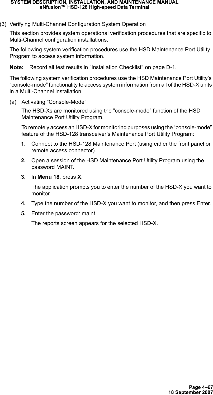
![Page 4–7518 September 2007SYSTEM DESCRIPTION, INSTALLATION, AND MAINTENANCE MANUALeNfusion™ HSD-128 High-speed Data Terminal 10. Type the appropriate COM port (1 or 2—typically 1), and then press Enter. 11. To proceed with the load, press Enter.Note: If you press Esc, the application aborts the software load. Only press Esc if you want to discontinue the software load procedure.Communication with the HSD or HSD-X transceiver is established. The following screen appears. As shown in the example screen, a percentage (%) progress indicator appears on the screen showing load status. Once the load is complete, a confirmation message briefly appears on the screen indicating that the file has been successfully loaded. The DOS window then closes and the HSD resets.This completes the load of the Control Processor software selected in step 9. 12. When software load is finished, reset or cycle the power on the HSD of HSD-X transceiver. 13. If no other software loads are required, proceed to Verifying the Software Load. 14. In the event that the load fails, restart the load from the beginning of the Loading Control Processor Software Procedure. If after two attempts the load still does not complete successfully, assume that the software disks may have been corrupted or the software is incompatible with the hardware configuration. Contact EMS SATCOM product support for assistance.HSD/HST LOADER V3.0 -- Mon Mar 24 12:12:17 2003which target ? 0 = control processor 1 = channel card #1 2 = channel card #2 3 = HPA application 4 = data i/o card 5 = HPA application with manual setup 6 = HPA application plus boot with manual setup 7 = HPA application plus boot 8 = channel card #1 boot code 9 = channel card #2 boot code 11 = channel card #1 pic code 12 = channel card #2 pic code 13 = HCM application 14 = HST ORT 15 = HSD ORT 16 = HSD-X ORT?) 0File name, which contains the firmware image? Adt70.binThis download will require one of the PC's COM ports. (1, 2, etc) [1] ?1Connect COM1 of this PC to the maintenance port of the data terminal.Hit <ESC> to abort, or <ENTER> to proceedEstablishing communication to the data terminal -- DO NOT CYCLE THE POWER !!Hit ESC to abort.DATA TERMINAL APPARENTLY READY TO ACCEPT PROGRAMswitching to 57.6 kbaudloading adt70.bin1% 5% 10%](https://usermanual.wiki/EMS-Technologies-Canada/HSD-X/User-Guide-1275806-Page-313.png)
![Page 5–418 September 2007SYSTEM DESCRIPTION, INSTALLATION, AND MAINTENANCE MANUALeNfusion™ HSD-128 High-speed Data Terminal4. Instructions for Continued Airworthiness, FAR 25.1529This section presents the special instructions and maintenance requirements for continued airworthiness of the HSD High-Speed Data Transceiver. Installation of the HSD on an aircraft by supplemental type certificate (STC) or Form 337 obligates the aircraft operator to include the maintenance information supplied by this manual in the operator’s Aircraft Maintenance manual and the operator’s Aircraft Scheduled Maintenance Program. A. Instructions for Continued Airworthiness ProceduresThe following paragraphs describe all maintenance requirements and instructions for continued airworthiness of the HSD or HSD-X transceiver. a. This manual contains maintenance information for the HSD and HSD-X units (including system description, system operation, removal, installation, test and fault isolation, and maintenance and repair). b. Add the LRU part numbers and other necessary part numbers contained in this manual to the aircraft operator’s appropriate, aircraft illustrated parts catalog (IPC). c. Add all wiring diagram information contained in this manual to the aircraft operator’s appropriate aircraft Wiring Diagram Manuals. d. HSD and HSD-X transceivers are considered on-condition units. No additional or routine maintenance is required. e. If an HSD or HSD-X transceiver is inoperative, remove the unit, secure cables and wiring, collar applicable switches and circuit breakers, and placard them as “inoperative.” Before flight, revise the equipment list and weight and balance data as applicable and record the removal of the unit in the log book [refer to section 91.213 of the FAR or the aircraft’s minimum equipment list (MEL)]. f. HSD and HSD-X transceivers are not field-repairable. All units must be returned to the EMS SATCOM factory or authorized repair centers for repair. Instructions for the removal of the unit for repair are provided in this section. g. Repaired units must be re-installed on the aircraft in accordance with the instructions provided in this manual. The operation of all repaired units must be verified using the operational verification tests and procedures provided in this manual before being approved for return to service. All special tools required to test the unit for approval for return to service are listed and described in "Test and Fault Isolation" on page 4-1. Approval for return to service must be entered in the logbook as required by section 43.9 of the FAR. h. The following scheduled maintenance tasks must be added to the aircraft operator’s appropriate aircraft maintenance program:• Recommended periodic scheduled servicing tasks: None required.• Recommended periodic inspections: None required.• Recommended periodic scheduled preventative maintenance tests (tests to determine system condition and/or latent failures): None required.](https://usermanual.wiki/EMS-Technologies-Canada/HSD-X/User-Guide-1275806-Page-348.png)