Elbit Systems Land and C4I Tadiran
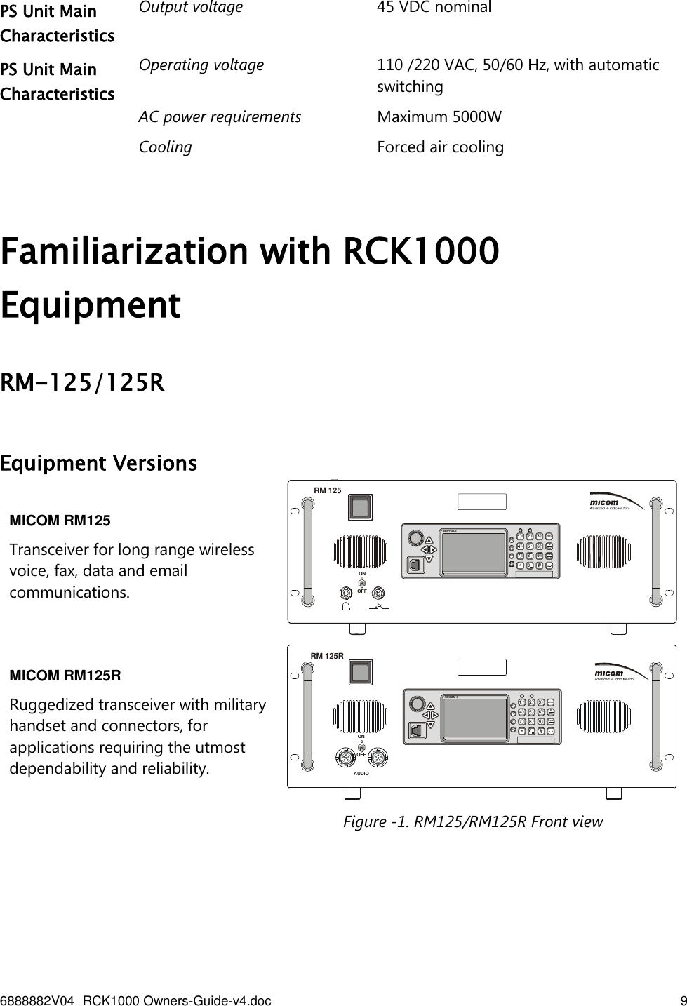
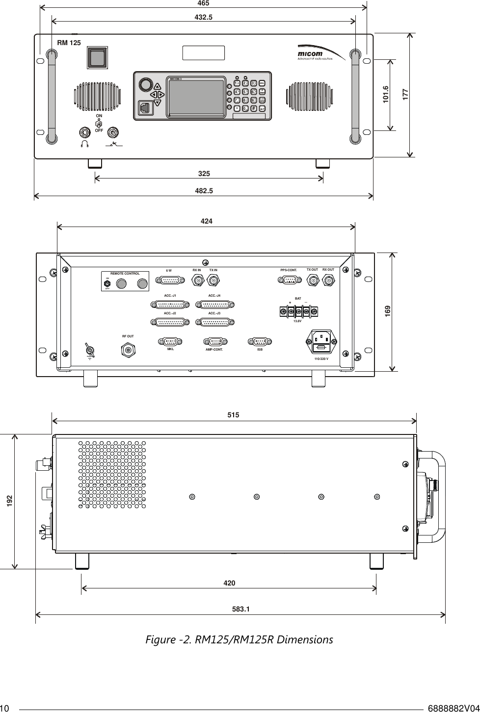
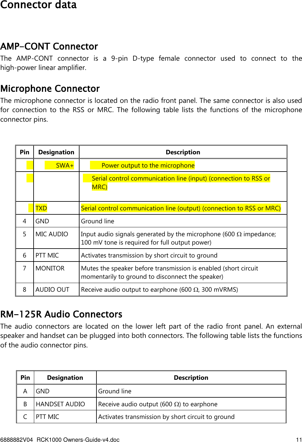
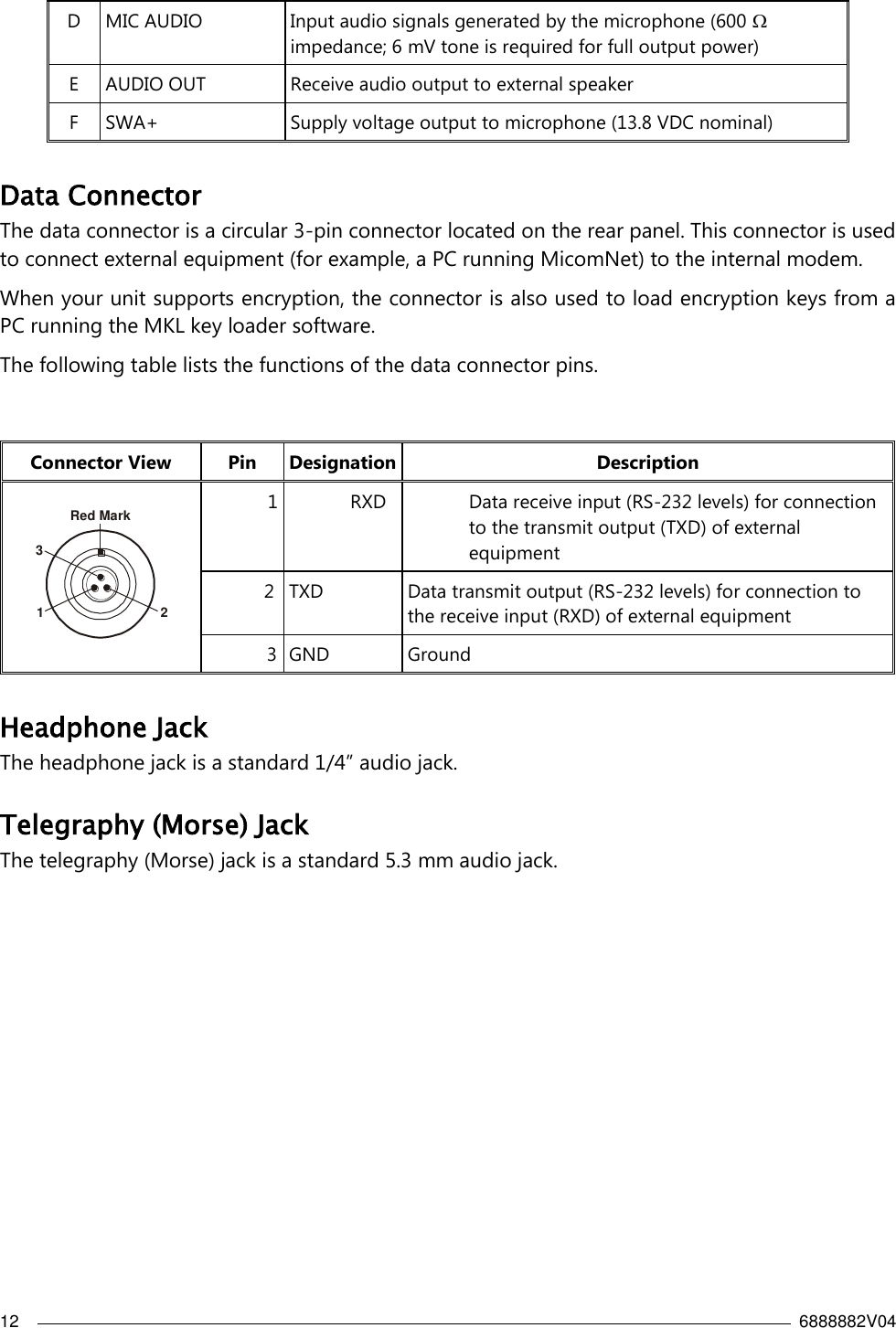
 MICOM-RM1KW Licensed Non-Broadcast Station Transmitter - RCK-1000 User Manual RM1200

Elbit Systems Land and C4I - Tadiran Ltd. Licensed Non-Broadcast Station Transmitter - RCK-1000 RM1200

User Manual

6888882V04 RCK1000 Owners-Guide-v4.doc    1   RCK1000 1kW Power System  Owner’s Guide  Table of Contents Introduction .................................................................................................................................................. 3 1KW System Description .......................................................................................................................... 3 Functional Description .............................................................................................................................. 4 RM-125/125R radio .............................................................................................................................. 4 1KW Amplifier ........................................................................................................................................ 5 PS Unit ....................................................................................................................................................... 6 RCK1000 Main Technical Characteristics ........................................................................................... 7 Familiarization with RCK1000 Equipment ........................................................................................... 9 RM-125/125R ......................................................................................................................................... 9 Equipment Versions ................................................................................................................... 9 Connector data ............................................................................................................................ 11 AMP-CONT Connector.............................................................................................................. 11 Microphone Connector............................................................................................................. 11 RM-125R Audio Connectors ................................................................................................... 11 Data Connector ............................................................................................................................ 12 Headphone Jack .......................................................................................................................... 12 Telegraphy (Morse) Jack ........................................................................................................... 12 Display Functions ........................................................................................................................ 13 Display Organization ................................................................................................................. 13 Mode and Function Indications ............................................................................................. 14 RF Level Indications .................................................................................................................... 14 1KW Power amplifier ........................................................................................................................ 15 1KW PA Front panel ................................................................................................................... 15 1KW PA LCD Functions ............................................................................................................. 16 1KW PA Rear Panel ..................................................................................................................... 19 Power supply unit .............................................................................................................................. 20
2    6888882V04  PS Front Panel .............................................................................................................................. 20 PS Rear Panel ................................................................................................................................ 21 RCK1000 Equipment Installation .................................................................................................. 23 Safety ............................................................................................................................................... 23 Installation Planning Guidelines ............................................................................................ 24 Grounding ...................................................................................................................................... 24 Power Requirements .................................................................................................................. 24 Cooling ............................................................................................................................................ 24 Installation Data ........................................................................................................................... 24 Antenna System ........................................................................................................................... 25 Antenna Feed System ....................................................................................................................... 25 Preparations for Installation .................................................................................................... 26 Installation Procedure ............................................................................................................... 27 RCK1000 Operation ............................................................................................................................. 29 General ................................................................................................................................................... 29 Preparations for Operation ............................................................................................................ 29 Calibration Procedure....................................................................................................................... 29 Equipment Turn-On .......................................................................................................................... 30 Operating Instructions ..................................................................................................................... 32 Equipment Turn-Off .......................................................................................................................... 32
6888882V04 RCK1000 Owners-Guide-v4.doc    3   Introduction This  manual  covers  the  installation  and  operation  of  the  MICOM  RCK1000  1KW  system.  The MICOM RM125 or RM125R, part of the MICOM-3 line of HF-SSB radio sets, is used as exciter and controller to for the 1KW amplifier . The amplifier is powered by a separate power supply unit .  The complete 1KW transceiver system is installed in a 19” rack.    1KW System Description The RCK1000, expands the MICOM-3 product line by offering higher transmit power (up to 1KW, PEP and average), and thus longer reach and improved communications under bad propagation conditions and/or strong interference.  The RCK1000 consists  of three units  placed in   rack mounting:  RM-125/RM-125R transceiver ,     1KW RF  linear power amplifier and    an AC-powered PS  unit. The equipment is  well suited  for base station applications, and can be directly connected to a wide range of broadband or tuned antennas, including whip, dipole, traveling wave, delta, and semi-delta antennas. The 1KW amplifier is optimized for operation in conjunction with the RM125 or RM125R radio set  as  exciter  and  controller,  using  a  dedicated  communication  interface  and  a  flexible handshaking protocol (interface cable kit, option G156, for connecting the 1KW amplifier to the RM125/RM125R).  The  RM125/RM125R  controls  the  1KW  amplifier  operation,  enables  the operator to select the nominal transmit power, and the 1KW amplifier provides ALC feedback to adjust the RM125/RM125R drive power to the optimum level.   Caution Before putting a new RCK1000 into operation, it is necessary to calibrate the  system  to  obtain  the  correct  transmit  power  (this  calibration  must also  be  performed after  either  the  exciter,  or  the  amplifier  is  replaced). Calibration  instructions  for  the  recommended  exciter,  RM125/RM125R, appear in the Publication 2072-09538-00, “Radio Service Software (RSS), User’s Guide” for RSS version V3.0 or higher.  Protection circuits monitor the various operating conditions, and prevent damage to the  1KW system by taking appropriate action, in accordance with the detected problem. The RCK1000 has several status indicators, and a front-panel LCD that enables the operator to monitor the operation of the subunits: active frequency ,  actual forward and reflected power (or VSWR),  report problems such as the activation of protection circuits or technical malfunctions.  A serial RS-232 asynchronous interface can be used for maintenance and calibration, using any data communication terminal , and the micom radio programming application. The 1KW amplifier is active only in the transmit mode: when not powered, in the receive mode, and  also  after  the  protection  circuits  are  activated,  the  1KW  amplifier  switches  to  the  bypass mode, and directly connects the radio set to the antenna system.
4    6888882V04  Functional Description RM-125/125R radio  RM-125/125R radio functions as an exciter in the RCK1000 system.   The RM125/RM125R radio  set  includes a  standard MICOM-3 transceiver, with a 110/220 VAC, 50/60 Hz power supply contained in a compact chassis, suitable for installation in a 19” rack or desktop. Internal cooling fans allow for continuous-duty data transmission and operation over a wide temperature range. The radio set features four accessories connectors located on the rear panel to facilitate the connection of optional accessories. The AC input voltage range (110/220VAC, 50/60Hz) is automatically switched allowing operation in the United States of America as well as in other countries. As a backup, the RM125/RM125R can also operate on 13.8 VDC power from an external lead-gel or lead-acid battery, which can be automatically charged by the internal AC power supply. When an external battery is connected, the RM125/RM125R can continue operating on battery power during an AC mains failure. This feature allow the RCK1000 system to continue working  in lower  transmit power, with the 1kw amplifier automatically bypassed , in case of power fail.  Features :   Automatic  Link  Establishment  per  FED-1045  &  MIL-STD-188-141B  standards  (JITC certified).  Full  interoperability  with  other  manufacturers'  radios  complying  with  the  same  ALE standards.  ISB (Independent Side Band) option (option G191).  Remote control option (options G420, G422).  A  built-in  voice  quality  system  utilizes  proprietary  algorithms  to  filter  out  background noises, giving users exceptional communication clarity.  Selectable bandwidth allows fine tuning for optimal voice and data communications.  Voice-activated digital squelch.  New  control  head  features  a  large  LCD,  full-dot  matrix  digital  display  and  an  enhanced keypad for programming and set-up.  Multiple language display available.  Transceiver can be controlled using PC and programming application.  Remote  control  configuration,  allows  the  transceiver  to  be  operated  from  a  remote location.  The  optional  2-wire  remote  control  head  (option  G420)  provides  control  at  a distance of up to 5 km; the G422 6-wire option enables remote control over leased lines, optical fibers or microwave links, and thus the control range is virtually unlimited.
6888882V04 RCK1000 Owners-Guide-v4.doc    5   1KW Amplifier  The 1KW amplifier consists of the following main functions:  Linear  RF  power  amplifier  covering  the  HF  band.  The  RF  amplifier  consists  of  4 independent amplification modules, whose outputs are combined to obtain the required RF output power. The RF drive signal, applied to the RF IN connector, is amplified to the appropriate level, as selected on the RM125/RM125R.  Harmonic filter.  This  is  a  low-pass  filter  whose  purpose  is  to  attenuate  harmonics  and other undesired signals at frequencies above the actual operating frequency, before the amplified output signal is applied to the RF OUT connector. The filter has 8 sub-bands: the filter that fits the operating frequency is automatically inserted in the transmit path. The required frequency information is received from the RM125/RM125R; in addition, the 1KW amplifier measures the actual frequency of the RF drive signal as part of its tuning process (if the frequency cannot be measured, the highest band is selected).  Bypass  circuits.  These  circuits  automatically  bypass  the  1KW  amplifier  and  establish  a direct path between the RF IN and RF OUT connectors when power is not available, or a critical malfunction is detected.  Control  circuits.  These  circuits  control  1KW  amplifier  operation,  interface  with  the exciter/controller unit (RM125/RM125R), and  take action to protect the amplifier when necessary.  Cooling  subsystem,  includes  internal  fans  that  enable  operation  over  a  wide  range  of temperatures.  Overdrive Protection The  input  power  is  automatically  adjusted  by  an  automatic  level  control  to  achieve optimal operating conditions for the amplifier. However, if the input drive power exceeds about 80W the protection circuits prevent damage to the 1KW amplifier by bypassing it.  High VSWR Protection  To  obtain  maximum  forward  power,  the  amplifier  should  be  connected  to  a  low  VSWR antenna system.  In case of excessive VSWR, for example, because of mismatch or damage to antenna system and/or feed cables, the ALC circuits prevent damage by reducing the transmit power to safe values.  However, in case of excessive mismatch (for example, short or open circuit), the protection circuits  switch  the  1KW  amplifier  to  the  bypass  mode:  in  this  case,  the  transceiver  is directly connected to the antenna.   Overheating Protection Special circuits protect the 1KW amplifier against overheating. If the temperature is too high to enable full-power operation, the output power is automatically halved, until the temperature  returns  to  normal.  However,  if  the  temperature  exceeds  the  maximum allowed  limit  and  damage  may  be  caused,  the  protection  circuits  are  activated  and bypass the amplifier.
6    6888882V04   Imbalance Protection When a fault, power failure or other type of failure prevents normal operation of one or more of its internal amplification modules, the 1KW amplifier is automatically bypassed. PS Unit  The  PS  unit  is  a  custom  design  that  includes  6  JWS-600-48  standard  power  supply  modules manufactured  by  Lambda  Inc.  (see  manufacturer’s  manual  for  complete  information  on  these modules),  contained  in  a  compact  chassis  suitable  for  installation  in  19”  racks.  The  individual modules  automatically share  the  load,  without  any  special  alignments.  The  assembled  PS  unit has been assigned a custom-design manufacturer number (YM-02-670B).  The PS unit operates on 110/220  VAC, 50/60  Hz. The AC  input voltage range is  automatically switched between 110 and 220 VAC,  and  therefore the  equipment  can be used in the United States  of  America  as  well  as  in  other  countries.  Internal  cooling  fans  enable  operation  over  a wide range  of  temperatures. The  PS  unit includes  two  independent power supply  subsystems, each providing +45V to two of the four amplification modules in the 1KW amplifier. Protection circuits monitor each output, and provide indications on front panel indicators in case the output voltages  deviate  by  more  than  25%  from  the  nominal  value;  if  an  output  voltage  increases beyond the maximum limit, the corresponding power supply subsystem is turned off, to prevent damage to the 1KW amplifier.
6888882V04 RCK1000 Owners-Guide-v4.doc    7   RCK1000 Main Technical Characteristics  General Number of channels 200   Transmission frequency range Emission modes 1.6 to 30 MHz  J3E, H3E, R3E ,J2A, J2B, H2A, H2B, R2A, R2B  Transmit power (PEP and average) User-selectable levels  Max:   1000W  High:   800W  Medium:   500W  Low:   300W  Reception frequency range 100  kHz to 30 MHz   Sensitivity (SINAD) 0.5 uV for 10 dB SINAD  Audio bandwidth 350 to 2700 Hz  Data bandwidth 300 to 3300 Hz  Frequency stability 0.6 ppm (0.1 ppm optional)  Frequency resolution 10 Hz  Number of accessories connectors 4   Operating Modes  Transmit mode (PTT controlled)  Bypass mode (input connector connected to output connector with 1KW amplifier not powered, in the receive mode, or after protection is activated)   Tuning (automatic detection of transmit signal frequency)
8    6888882V04   Control and maintenance interfaces  Serial RS-232 asynchronous maintenance ports               drive power  40W nominal, maximum 80W   Pilot tone for operating frequency detection: 5W   Nominal input and output impedance 50    Intermodulation products  Less than -25 dB below each tone  Non-harmonic products Less than -60 dB  Harmonics  Carrier suppression(SSB-J3E)   Carrier level (AME-H3E) Less than -50 dB -50 dB/PEP 0 to -6 dB/PEP   Load mismatch  Full transmit power for VSWR up to 1.3:1  Reduced transmit power for higher VSWR  Full protection against short/open circuit  Overheating protection  Reduced transmit power for high temperature  Bypass in case of excessive temperature  Power requirements   Maximum 2000W in SSB mode  Maximum 3500W in CW mode  Cooling  Forced air cooling Dimensions Height 102 cm  Width 53.2 cm  Depth 60 cm  Weight 80 kg
6888882V04 RCK1000 Owners-Guide-v4.doc    9   PS Unit Main Characteristics Output voltage  45 VDC nominal PS Unit Main Characteristics  Operating voltage 110 /220 VAC, 50/60 Hz, with automatic  switching  AC power requirements  Maximum 5000W Cooling Forced air cooling    Familiarization with RCK1000 Equipment  RM-125/125R  Equipment Versions MICOM RM125  Transceiver for long range wireless voice, fax, data and email communications. RM 125ONOFFMICOM-3 1?@/PRS7*QJ MK NL O5 6TUV8 9ADB EC F2 30#YWZXMENUEscPGPSALARMF1F2F3F4GHI4 MICOM RM125R Ruggedized transceiver with military handset and connectors, for applications requiring the utmost dependability and reliability. RM 125RMICOM-3 1?@/PRS7*QJMKNLO5 6TUV8 9A DBEC F2 30#YWZXMENUEscPGPSALARMF1F2F3F4GHI4ONOFFAUDIO               Figure -1. RM125/RM125R Front view
10    6888882V04  RM 125ONOFFMICOM-3 1?@/PRS7*QJ MKNL O5 6TUV8 9ADB ECF2 30#YWZXMENUEscPGPSALARMF1F2F3F4GHI4432.5465101.6177325482.5515420583.1192424169TX OUT RX OUTACC.-J1 ACC.-J4ACC.-J2 ACC.-J3PPS-CONT.MKL AMP-CONT. ISBRF OUTREMOTE CONTROLONOFFBAT+_13.8V110/220 VTX INRX IN6 W Figure -2. RM125/RM125R Dimensions
6888882V04 RCK1000 Owners-Guide-v4.doc    11   Connector data   AMP-CONT Connector The  AMP-CONT  connector  is  a  9-pin  D-type  female  connector  used  to  connect  to  the high-power linear amplifier.  Microphone Connector The microphone connector is located on the radio front panel. The same connector is also used for  connection  to  the  RSS  or  MRC.  The  following  table  lists  the  functions  of  the  microphone connector pins.  Pin Designation Description  1  SWA+   Power output to the microphone  2  RXD  Serial control communication line (input) (connection to RSS or MRC)  3 TXD Serial control communication line (output) (connection to RSS or MRC) 4 GND Ground line 5 MIC AUDIO Input audio signals generated by the microphone (600  impedance; 100 mV tone is required for full output power) 6 PTT MIC Activates transmission by short circuit to ground 7 MONITOR Mutes the speaker before transmission is enabled (short circuit momentarily to ground to disconnect the speaker) 8 AUDIO OUT Receive audio output to earphone (600 , 300 mVRMS)  RM-125R Audio Connectors The  audio  connectors are  located  on  the  lower  left  part  of  the  radio  front  panel.  An  external speaker and handset can be plugged into both connectors. The following table lists the functions of the audio connector pins.  Pin Designation Description A GND Ground line B HANDSET AUDIO Receive audio output (600 ) to earphone C PTT MIC Activates transmission by short circuit to ground
12    6888882V04  D MIC AUDIO Input audio signals generated by the microphone (600  impedance; 6 mV tone is required for full output power) E AUDIO OUT Receive audio output to external speaker F SWA+ Supply voltage output to microphone (13.8 VDC nominal)  Data Connector  The data connector is a circular 3-pin connector located on the rear panel. This connector is used to connect external equipment (for example, a PC running MicomNet) to the internal modem.  When your unit supports encryption, the connector is also used to load encryption keys from a PC running the MKL key loader software.  The following table lists the functions of the data connector pins.  Connector View Pin Designation Description Red Mark132  1  RXD  Data receive input (RS-232 levels) for connection to the transmit output (TXD) of external equipment  2 TXD Data transmit output (RS-232 levels) for connection to the receive input (RXD) of external equipment   3 GND Ground   Headphone Jack The headphone jack is a standard 1/4” audio jack. Telegraphy (Morse) Jack The telegraphy (Morse) jack is a standard 5.3 mm audio jack.
6888882V04 RCK1000 Owners-Guide-v4.doc    13   Display Functions  Display Organization  The following table lists the Display indications No.  Designation  Description 1 Mode indicator Indicates the current working mode (e.g., channel, frequency, ALE, etc.) or the action being performed (e.g., programming, testing, etc.) 2 Work area Displays information on the current working mode, the main operating parameters, the active options, status, etc. 3 Transmit level indicator  In the transmit mode, displays the relative transmit power 4 Receive level indicator  In the receive mode, displays the relative received signal strength 5 Tx bar Appears when the radio is transmitting 6 More options Icon The presence of this icon indicates that more options can be displayed in the options area. When this icon appears, press the MORE key to see menu options 7 Options display area Displays a list of options you can select, by pressing the corresponding key, in the current working mode
14    6888882V04  Mode and Function Indications  The following indications may appear in the work area of the LCD display. Indication Meaning USB Using upper sideband for transmission and reception  LSB Using lower sideband for transmission and reception  ISB-U Independent sideband (ISB) mode (option) is enabled, and the main sideband is USB  ISB-L Independent sideband (ISB) mode (option) is enabled, and the main sideband is LSB  SQ Squelch is active: the speaker is turned on only when the radio identifies speech, to prevent reception noise from being heard. For Micom-3R, the squelch function also effects the handset MON When using ALE, indicates that the speaker is normally off, and is automatically turned on when the link is established. For Micom-3R, the monitor function also effect the handset AGC Non-standard AGC mode (AGC off, or fast AGC) has been selected BW Non-standard bandwidth has been selected that is, any bandwidth except 2.7 kHz (the bandwidth appears next to the BW indicator, for example, 3.3 (3.3 kHz) in the screen shown above) NB Noise blanker is active CLAR Clarifier is active (you selected a frequency deviating from the nominal channel frequency) NF Notch filter is active  RF Level Indications Indication  Meaning  Strong received signal  Weak received signal Received RF signal strength indication, displayed when the radio is in the receive mode. The height provides a relative indication, which may fluctuate as a result of fading, etc.  – Full transmit power – Relative transmit power  – Low transmit power  – Reflected power Transmit bar, appears when the radio is switched to the transmit mode (for example, when the PTT is pressed). Its length indicates the maximum radio transmit power in the selected mode (MAX, HIGH, MED or LO). The triangle height indicates the instantaneous relative transmit output power, and therefore it fluctuates as a result of modulation.  The relative reflected power is indicated by the base line: its length indicates the fraction of power reflected because of antenna VSWR (the length should be small relative to the total height of the transmit bar, which is proportional to the forward power)
6888882V04 RCK1000 Owners-Guide-v4.doc    15   1KW Power amplifier  1KW PA Front panel   Figure  identifies the items located on the front panel of the 1KW amplifier, and the following table explains their functions. RM-1200 FAULT BYPASS 1000HF  SSB - AMPLIFIERTXDISPLAY MODE6 51 24 3 Figure 3. 1KW PA Front Panel The following table lists the 1KW PA Front Panel Items: Item Description Function 1 Display  LCD display. See the following section for displayed information   2 DISPLAY MODE push-button Selects the type of information presented on the display  3 BYPASS indicator  Lights when the 1KW amplifier is in the bypass mode . The 1KW amplifier is bypassed when the radio is in the receive mode. It is also bypassed when it is not powered, or a fault or abnormal condition prevents its normal operation 4 TX indicator  Lights when the 1KW amplifier is switched to the transmit mode 5 FAULT indicator  Lights when a fault in the 1KW amplifier does not allow normal operation. In this case, the  amplifier remains in the bypass mode until the fault is corrected. Flashes when an operational problem, for example, high temperature or excessive VSWR, activates the protection circuits and causes the amplifier to reduce its output power or temporarily switch to the bypass mode 6 Air intake vents Intake vents for cooling air, with removable covers that provide access to the dust filters
16    6888882V04  1KW PA LCD Functions  The LCD is used to display information on the operational conditions of the 1KW amplifier, and status  information.  The  LCD  comprises  2  rows,  and  therefore  it  is  necessary  to  split  the information on four different display pages of 2 rows each.  The first row of each page always presents two items:  The current mode indicator, RX or TX  The operating frequency, in MHz, as detected during the tuning process. The frequency is measured with a resolution of 10 kHz,  and therefore, if you need to know  the exact transmit frequency, always use the RM125/RM125R frequency display.  The information displayed in the second row changes with the specific page. To select a page, press  the  DISPLAY  MODE  push-button  display  as  required  (scrolling  is  cyclical).  The  selected page remains on display, until you select another page. The  information  presented  on  each  page  is  explained  in  the  following  table.  The  pages  are presented in the order they appear when scrolling by means of the DISPLAY MODE push-button.  The following table lists the 1KW PA LCD Functions   No. Typical Page  Function 1  Normal receive screen.  When transmitting (TX), the second row displays the  forward (FWD) power in watts, followed by the VSWR. 2  Alternative screen: when transmitting, displays the forward (FWD) and reflected (REV) power in watts. 3  Status screen (shown for receive – RX – mode). Displays the total number of faults and warnings detected in the unit. If either number is not 0, the FAULT indicator indicates the condition with the highest severity:  If the condition with the highest severity is a warning (FAULTS is 0, WARNING is not 0), the FAULT indicator flashes  If the condition with the highest severity is a fault (FAULTS is not 0), the FAULT indicator lights steadily 4  Fault (F) or warning (W) screen: displays the fault and /or warning detected in the unit.   Frequency  appears  only  after  successful  tuning:  before  tuning, and also  in  case the  tuning  fails,  no frequency is  displayed.  For example:  The forward and reflected power (or VSWR) values are automatically updated; fault and warning information is refreshed only after scrolling again to the same page.
6888882V04 RCK1000 Owners-Guide-v4.doc    17   Note The  displayed  value  may  fluctuate,  according  to  the  actual  power  measured  at  the instant the display has been updated. As a result, in all the transmit modes except CW (which  has  a  constant  modulation  envelope),  the  displayed  value  depends  on  the instantaneous  modulation  signal,  and  therefore  may  be  lower  than  the  selected nominal transmit power.  Protection  circuits are  reset  after  the  PTT  is  released,  but  may  be activated  again  if  condition persists.
18    6888882V04  The following table lists the 1kW PA Fault and Warning Messages   Type Message Meaning Corrective Actions Fault AMP#1  AMP#2 AMP#3 AMP#4 The corresponding amplifier module does not operate, for example, because its supply line fuse is blown, or a fault in the module itself. 1KW amplifier is in the bypass mode and cannot transmit Service is required RF IN OVERLOAD Excessive drive power supplied to the RF IN input.  1KW amplifier is in the bypass mode and will not transmit until the condition is corrected When using the amplifier with a driver other than RM125/RM125R, check the maximum transmit power of the driver unit. When using the RM125/RM125R, first check for proper connection of the control cable between the RM125/RM125R AMP-CONT connector and the 1KW amplifier EXCITER CONTROL connector. If problem persists, service is required (adjustment of operating conditions using the MONITOR program) PWR OUT LATCH Technical problem related to the harmonic filter.  1KW amplifier is in the bypass mode and cannot transmit Service is required TEMP OVERHEAT Excessive internal temperature. 1KW amplifier is in the bypass mode and cannot transmit until it cools Wait for the amplifier to cool. Check that the air intake vents and exhaust vents are free. If condition recurs, power down the amplifier and clean the dust filters (the filters are reached after removing the intake covers, which are fastened by four screws each) Warning PWR OUT REDUCED Internal temperature is too high.  1KW amplifier transmits at reduced (half) power as long as problem persists See TEMP OVERHEAT HIGH VSWR Excessive reflected power.  1KW amplifier is in the bypass mode and will not transmit until the condition is corrected Check the antenna feed cable, starting from the RF OUT connector, and up to the antenna. Also check that no damage is evident to the cables and to the antenna itself
6888882V04 RCK1000 Owners-Guide-v4.doc    19   The following table lists the 1KW PA Fault and Warning Messages (Cont.) Type Message Meaning Corrective Actions Warning (Cont.) INVALID FREQ 1KW amplifier could not determine the operating frequency. The frequency is measured by automatically causing the RM125/RM125R to transmit a low level (about 5W) pilot tone for a few seconds after each frequency change, and also whenever the ENT key of the RM125/RM125R is pressed Check the cable connections between the RM125/RM125R and the 1KW amplifier. Repeat the frequency measurement process by pressing the ENT key of the RM125/RM125R and monitor the RM125/RM125R display: it should switch to the transmit mode for a few seconds, and its transmit display should include at least two bars 1KW PA Rear Panel Figure   identifies the  items located  on  the rear  panel  of the  1KW amplifier, and  the following table explains their functions. 67542 31EXCITER CONTROL  MONITORRF OutRF In+48VDC  Figure 4. 1KW PA Rear Panel Item Description Function 1 RF IN Connector  N-type connector for RF connection to the RM125/RM125R:   In the receive or bypass mode, serves as output for receive signals  In the transmit mode, serves as input for RF drive signals 2 +48VDC connector   7-pin circular connector for connection to DC power source 3 Grounding screw Connection of ground to the 1KW amplifier
20    6888882V04  The following table lists the 1KW PA Rear Panel Items (Cont.) Item Description Function 4 MONITOR connector  9-pin D-type female connector for connection to maintenance monitor (ASCII terminal or PC with terminal emulation program)  5 EXCITER CONTROL Connector  25-pin D-type female connector, contains the control interface that enables  the RM125/RM125R to control the 1KW amplifier 6 Exhaust Vents  Cooling air exhaust vents 7 RF OUT Connector  N-type connector for RF connection to antenna system:  In the receive or bypass mode, serves as input for receive signals  In the transmit mode, serves as output for amplified RF signals  Power supply unit   PS Front Panel  Figure   identifies the  items  located  on  the  front panel  of the  PS  unit,  and  the following table explains their functions. OUT 1 OUT 2OK NG OK NGAC ONONOFF1 2 3 54 6 Figure 5. PS Front Panel
6888882V04 RCK1000 Owners-Guide-v4.doc    21   The following table lists the. PS Front Panel Items  Item Description Function 1 ON/OFF switch  Turns the PS on 2 AC ON indicator    Lights when the PS unit is powered 3 OUT 1 OK indicator  Lights when the power supply subsystem 1 operates normally  4 OUT 1 NG indicator  Lights when the output voltage provided by power supply subsystem 1 is not within 25% of its normal value. To protect the 1KW amplifier, the output voltage is automatically turned off in case it exceeds the maximum value. To attempt returning to normal operation, turn the PS off and then back on: if problem recurs, the PS unit must be serviced  5 OUT 2 OK indicator  Same as Item 3 for power supply subsystem 2  6 OUT 2 NG indicator  Same as Item 4 for power supply subsystem 2  PS Rear Panel Figure   identifies the  items  located  on  the  front panel  of the  PS  unit,  and  the following table explains their functions. OUT 1+V +V-V -V45V 45VOUT 2GNDAC INPUT110-230VAC/ 47~63HzLNGDC OUTPUT1 2 3 4 Figure 6. PS Rear Panel
22    6888882V04  The following table lists the PS Rear Panel Items  Item Description Function 1 OUT 1  +V, -V terminals Output voltage terminals of power supply subsystem 1 2 OUT 2  +V, -V terminals Output voltage terminals of power supply subsystem 2 3 AC INPUT strip Terminal strip, covered by a protective cover, for connection to AC power source:  L – line (phase) terminal  N – neutral terminal  G – ground terminal 4 Grounding screw Connection of ground to the 1KW amplifier
6888882V04 RCK1000 Owners-Guide-v4.doc    23   RCK1000 Equipment Installation Safety  Warning During installation work, strictly observe the applicable safety precautions and local regulations. Do not work on the antenna system during lightning storms.   Warning Proper grounding is essential for your safety, and for good communication performance.  Do not touch the antenna and the RF connectors while the 1KW amplifier and/or the exciter (RM125/RM125R or equivalent) operates. During transmission, high RF voltages appear at the RF connectors, the antenna cables, and on the antenna itself. These voltages may cause severe injury or death on contact. Make sure the antenna is not located near high-voltage lines. All personnel must be familiar with the applicable safety requirements before attempting to install or operate the 1KW amplifier and/or the exciter (RM125/RM125R or equivalent).  Severe injury or death could result from failure to comply with the safety practices.  Warning High AC voltage, capable of causing death or injury on contact, is present on the AC INPUT terminal strip at the rear panel of the PS unit when the unit is connected to a power source.    Caution The RCK1000 units are a two-person lift. Make sure that help is available during the installation activities.  Caution Before putting a new RCK1000 into operation, it is necessary to calibrate the  system  to  obtain  the  correct  transmit  power  (this  calibration  must also  be  performed  after  either  the  exciter,  or  the  1KW  amplifier,  is replaced).  Calibration  instructions  for  the  recommended  exciter, RM125/RM125R, appear in the Publication 2072-09538-00, “Radio Service Software (RSS), User’s Guide” for RSS version V3.0 or higher.
24    6888882V04  Installation Planning Guidelines  This  section  provides  the  additional  information  necessary  for  planning the  installation  of  the RCK1000 system . Grounding Failure to provide proper grounding to each system unit (RM125/RM125R, 1KW PA and PS unit, and to the optional PPS) and to the rack in which these units are installed will degrade system operation  and  cause  RF  voltage  to  be  present  on  the  equipment  chassis.  A  possible  serious hazard to personnel could result, as well as equipment malfunction.  Wide  copper  straps,  as  short  as  possible,  must  be  used  for  grounding.  These  straps  must  be clamped  or  bonded  to  a  common  grounding  point  within  the  rack,  which  is  connected  to  a reliable, low-resistance grounding system.   Power Requirements The RCK1000 PS unit requires AC power at a nominal voltage of 110 or 220 VAC, 50/60 Hz. The PS unit will automatically select the appropriate voltage range. The maximum AC power consumption during high-power transmission is up to 5 kW. In  addition  to  the  circuit  breaker  or  fuse  protecting the  supply  line  to  the  RM125/RM125R, a suitably rated circuit breaker or fuse must be used to protect the supply line of the PS unit, and enable disconnection of its supply voltage during installation and maintenance. Cooling RCK1000  units  are  cooled  by  internal  fans.  Air  is  taken  in  through  the  front  panel  vents,  and discharged toward the rear. Therefore, make sure that sufficient free space is available around the equipment to enable free air flow. Do not stack equipment units: leave at least 1U free above and below each unit installed in the rack. Installation Data The RM125/RM125R, the optional Pre-Selector/Post-Selector (PPS) , the 1kW PA and the power supply , are intended for installation in the provided 19” rack. The interface cable kit for MICOM 1KW linear amplifier, option G156, is also intended for installation in the same rack. Each equipment unit has front-mounted brackets for attachment. To provide convenient access during  maintenance,  each  equipment  unit  is  installed  on  slides  capable  of  supporting  the equipment weight. The rack itself must be securely fastened to the floor, before starting the installation activities. Sufficient  front  and  rear  clearance  is  required  to  permit  convenient  access  to  front  and  rear
6888882V04 RCK1000 Owners-Guide-v4.doc    25   panels,  as  well  as  for  removal  and  installation  of  equipment  units,  connection  of  cables,  and maintenance.  Antenna System Antenna systems are  selected in  accordance  with  the  specific communication  requirements of each  customer:  many  HF  antenna  types  are  available,  each  providing  different  radiation characteristics  to  meet  different  communication  requirements.  Therefore,  the  selection  and installation  of  an  antenna  system  is  customer’s  responsibility.  If  necessary,  contact  the manufacturer or your local representative for additional information. The antenna system must provide a matched termination at the operating frequency, and must be capable of handling the maximum power output of the system.  Antenna Feed System  The antenna feed  system comprises any cables, panels and  matrices, and any accessories that carry HF signals between the RCK1000 and the antenna itself.  The high output power of the RCK1000 requires particular attention to the power rating of the antenna  system,  and  to  the  use  of  a  high-quality,  low-loss  feed  cable.  Appropriate  safety measures must be taken to prevent people from touching the antenna, or even getting close to it. All the antenna feed system components, and in particular the feed cable, must have low loss and  be  capable of  carrying  the  maximum  power  output  of  the  RCK1000. Remember that  any power loss along the cable is signal loss! To protect yourself and the radio equipment against lightning strokes and accidental contact of antenna and/or feed cable with high voltage lines, a properly grounded coaxial protector must be installed at the point of entry of the feed cable into the building or communication shelter. The recommended protector type is IS-B50LN-C0 by PolyPhaser Corp. (also available from the manufacturer as Cat. No. 2072-09128-00).
26    6888882V04  Preparations for Installation Before  starting  the  installation  of  an  RCK1000,  review  the  installation  plan  and  make  the following checks: 1. Check that the rack is securely fastened to the floor. 2. Check  the  mounting  surfaces,  and  the  rack  mounting  holes.  Thoroughly  clean  the mounting surface and remove all paint, grease and dirt from the holes to provide a better grounding connection. 3. Check availability of AC power, and grounding arrangements. 4. Check  antenna  installation,  in  accordance  with  the  antenna  installation  and  operation manual. 5. Check the cable runs between the 1KW amplifier and the prescribed antenna, including the coaxial protector. Make sure that the cables are securely fastened, and do not show signs of external damage. 6. Make sure  that you have the  cable  sets  needed for  the  installation, which includes  the amplifier  cable  set,  and cables  for  connecting to  the  exciter  unit  (for  example,  use  the cables in option G156 for connecting to the RM125/RM125R).
6888882V04 RCK1000 Owners-Guide-v4.doc    27   Installation Procedure  Note All the information appearing in this section is presented for the Micom 1KW amplifier set and the RM125/RM125R as exciter.  For  more  data  on  RM125/RM125R,  refer  to  the  “RM125/RM125R  Owner’s Guide”, Publication 6888882V02.    Refer to Figure  for a typical RCK1000 interconnection diagram . 1. Identify the installation position of each equipment unit in the rack. 2. Install each equipment unit in the prescribed installation position, fastening it by means of screws to the rack rails or to the drawer front. 3. Connect grounding straps from each grounding screw (located on the rear panels of the various units), to the prescribed cabinet’s grounding bar. 4. Set all the power switches on all the equipment front panels to OFF (down position).   Caution The 1KW PA unit does not have a power switch, and therefore it will start operating as soon as the RM125/RM125R is turned on, provided that the PS unit is already turned on.  5. Connect the RM125/RM125R unit as explained in its Owner’s Guide, to AC or the relevant DC power connections.  6. Connect the coax from the RM125/RM125R RF OUT connector to the RF IN connector of the 1KW amplifier. 7. Connect the control cable between the RM125/RM125R AMP-CONT connector and the 1KW amplifier EXCITER CONTROL connector. 8. Connect the antenna feed cable to the RF OUT connector of the 1KW amplifier.  9. Connect the DC power cable between the 1KW amplifier +48VDC connector and the four DC OUTPUT terminals of the PS unit. Pay attention to correct connection of the two pairs of leads to the DC OUTPUT terminals, with respect to polarity and OUT pair. 10. Connect the three leads of the PS unit AC power cable to the AC INPUT terminal strip, in accordance with the functions of each lead. After making the connections, make sure that the protective cover of the terminal strip is properly installed. 11. Connect the other end of the AC power cable of the PS unit to the prescribed outlet on the power distribution box of the cabinet.
28    6888882V04  ONREMOTE CONTROLACC-J4ACC-J313.8VAC110/220VRF OUTTo Antenna (via Coaxial Protector)To ACSourceControlCableDC PowerCableRM1200 (PA)RM125 (Exciter)PS UnitOFFBAT+-PPS-CONT   TX OUT  RX OUTTX IN RX INACC-J2ACC-J1MONITORRF OutRF In+48VDC OUT 1+V +V-V -V45V 45VOUT 2GNDAC INPUT110-230VAC/ 47~63HzLNGAMP-CONTEXCITER CONTROL DC OUTPUTLineNeutralGroundAC Power Cableto AC Source Figure 7. Typical RCK1000 System Connections
6888882V04 RCK1000 Owners-Guide-v4.doc    29   RCK1000 Operation General The  following  instructions  present  operating  procedures  of  the  system.    More  information  is detailed  in  the  “RM125/RM125R  Owner’s  Guide”,  Publication  6888882V02,  “Owner’s  Guide, MICOM-3F/3T/3R  HF-SSB  Transceivers”,  Publication  6886867J01,  and  the applicable  MICOM-3 Supplements that cover optional features. Preparations for Operation 1. Set the REMOTE CONTROL switch on the rear panel of the RM125/RM125R to the OFF (down) position. 2. For the RM125R, set the internal speaker switch to ON (up). Calibration Procedure The  manufacturer  calibrates  new  1KW  amplifier  systems,  to  ensure  that  the  RM125/RM125R transmit  level  matches  the  1KW  amplifier  requirements  at  each  of  the  four  system  transmit power levels (LOW, MED, HIGH, and MAX). However, after replacing the 1KW amplifier or the RM125/RM125R serving as its exciter, it is necessary to calibrate again the system. Calibration  instructions  for  a  1KW  amplifier  used  in  conjunction  with  the  RM125/RM125R  are given in “Chapter 12: Technician Mode” of Publication 2072-09538-00, “Radio Service Software (RSS) V3.0, User’s Guide” (previously Publication 68P02953C05-O).  The  calibration  procedure  is  described  in  Section  12.2:  “Power  Calibration”  of  the  RSS  User’s Guide. Before carrying out the  procedure,  make sure  to select the  1KW  amplifier power word option on the window that is opened by selecting Technician>Calibration. The calibration must be performed for each transmit level. The nominal transmit levels are as follows:  LOW: nominal transmit power of 300W.  MED: nominal transmit power of 500W.  HIGH: nominal transmit power of 800W.  MAX: nominal transmit power of 1000W. Exceeding  the  maximum  rated  power  of  the  1KW  amplifier  (1000  W)  may  damage  the equipment, and therefore it is highly recommended to adjust the MAX transmit power to 900W (that is, 0.5 dB below the rated maximum). This is a precaution that takes into consideration the accuracy of the equipment used to measure the output power.
30    6888882V04  Note If  no  equipment  capable  of  measuring  the  1KW  amplifier  transmit  power  is available, it is possible to use the 1KW amplifier own display to determine the transmit power. Do not use  this method, unless it  is  absolutely impossible to obtain appropriate test equipment.  Equipment Turn-On 1. Apply power to the RM125/RM125R by setting its AC power switch to ON (up). 2. Set the AC power switch on the PS unit to ON, and monitor its indications. The expected indications, as  well  as  what  to  do  if  a problem is  detected, are  described in  the  below table. 3. Turn the RM125/RM125R ON/OFF switch and volume control clockwise and adjust for a comfortable listening level. 4. The  1KW  amplifier  is  also  turned  on.  Monitor  its  power-up  indications.  The  expected indications, as  well  as  what  to  do  if  a problem is  detected, are  described  in  the  below table. 5. Select  the  prescribed  channel  and  operating  mode  of  the  RM125/RM125R.  Make  sure that the RM125/RM125R is programmed to use the 1KW amplifier (you should see AMP on the PROG>RAD>OPTS>ACC menu). Power-up Indications   Unit Expected Indication  What to do if not … PS Unit AC ON indicator lights Check that AC power is available, and that the PS unit is properly connected to the AC distribution panel OUT 1 and OUT 2 indicators light. NG 1 and NG2 indicators off The PS unit requires service.  Turn the PS unit off: do not attempt to continue using the 1KW amplifier until the problem is corrected. You can still transmit and receive using the RM125/RM125R (maximum transmit power – 125W) by selecting NONE on the PROG>RAD>OPTS>ACC menu.
6888882V04 RCK1000 Owners-Guide-v4.doc    31   1KW PA  All the front panel indicators flash together a few times as the unit performs its power-up initialization sequence, and then turn off If the FAULT indicator lights, a fault has been detected in the 1KW amplifier (you may read the problem by means of its from panel LCD). Service the 1KW amplifier. However, you can still transmit and receive using the RM125/RM125R by selecting NONE on the PROG>RAD>OPTS>ACC menu. If the BYPASS indicator lights while in the transmit mode, make sure to select AMP on the RM125/RM125R  PROG>RAD>OPTS>ACC menu. The 1KW amplifier tunes to the RM125/RM125R operating frequency. After successful tuning, its front panel LCD displays the selected frequency  Check for proper connection of the RF and control cables between the RM125/RM125R (or other exciter unit you are using), and the 1KW amplifier.  If tuning fails even after turning the equipment off and on again in the proper turn-on sequence described above, you are still able to transmit and receive using the RM125/RM125R by permanently bypassing the 1KW amplifier. For the RM125/RM125R, you bypass the 1KW amplifier by selecting NONE on the PROG>RAD>OPTS>ACC menu RM-125 The display turns on and shows SELF TEST for a few seconds.   If the display is too dim, adjust its brightness using  MENU > MORE > DIM > LEVEL. However, this change is temporary: the dimming level returns to the default setting (1) after 10 seconds. Each key pressing will extend the time-out interval by 10 seconds. If automatic dimming is enabled (DIM is YES), the display may turn off after a few seconds of inactivity. To cancel this feature, use MENU > MORE > PROG > RAD > PRMT > MORE > MORE > DIM to select NO for DIM.  If the self-test procedure is successfully completed, the radio automatically resumes operation in the last used mode (CHAN, FREQ, ALE, or SCAN). If a problem is detected during self-test, the display shows ERR and a code number, followed by a concise description of the error (if the description does not fit in one row, its parts alternate in the display). If the detected problem does not prevent using the radio, press EXIT to cancel the display and continue
32    6888882V04  Operating Instructions  You are now ready to start using the radio set. For the additional operating procedures, you may use the information appearing in the “RM125/RM125R Owner’s Guide”, Publication 6888882V02, and in the “Owner’s Guide, MICOM-3F/3T/3R HF-SSB Transceivers”, Publication 6886867J01. 1. During reception, you will see the receive indications (RX and the operating frequency) on the 1KW amplifier LCD. Note The  tune  indications  will  appear  whenever  you  change  the  operating frequency, and also whenever the ENT key of the RM125/RM125R is pressed. If the frequency cannot be identified, you will see an INVALID FREQ message, and it is not possible to transmit using the 1KW amplifier (the 1KW amplifier is bypassed).  2. When you press the PTT to start a transmission, the TX indicator of the RM-125 and on the  1KW amplifier lights, and you will see the transmit indications (TX and the operating frequency) on the LCD. The second row of the 1KW LCD displays the transmit power, and the VSWR.  Note During  normal  transmission,  the  TX  indicator  lights,  and  the  BYPASS  and FAULT indicators are off.  If the BYPASS and FAULT indicators light, the 1KW amplifier switched to the bypass mode because it either overheated to dangerous levels, or the antenna VSWR  is  too  high,  or because it  could not identify  the  operating frequency. You can read the information displayed by the LCD to get additional details. In this case: 1. If the operating frequency has not been identified, repeat the frequency measurement process by  pressing  the  ENT  key  of  the  RM125/RM125R and monitor the amplifier LCD display: it should switch to the transmit mode for a few seconds, and its transmit display should include at least two bars. 2. Check that the amplifier cooling fans operate normally, and that nothing blocks the air intake and exhaust vents.  3. Check  the  antenna  system  and  the  feed  cable  for  accidental disconnection or damage.  4. If problem persists after turning the equipment off and then on again in the proper sequence, service is needed. If  the  FAULT  indicator  flashes  but  the  BYPASS  indicator  is  off,  the  1KW amplifier halved its transmit power because it overheated. In this case, take the steps described in Item 2 above. Equipment Turn-Off 1. Turn  the  RM125/RM125R  off:  turn  the  front  panel  ON/OFF  switch  and  volume  control
6888882V04 RCK1000 Owners-Guide-v4.doc    33   fully counterclockwise, beyond the detent position. Now set its AC power switch to OFF. Note At this stage, the 1KW amplifier is also turned off.  2. Turn the PS unit off by setting its ON/OFF switch to OFF.

Navigation menu