Elcam Medical ACAL 13EAUPAWRLSYST Wireless Blood Pressure Transducer User Manual Wireless Transmitter Receiver
Elcam Medical ACAL Wireless Blood Pressure Transducer Wireless Transmitter Receiver
UserManual.wiki
>
Elcam Medical ACAL
>
13EAUPAWRLSYST User Manual
User Manual
Navigation menu
Upload a User Manual
Namespaces
Wiki Guide
HTML
PDF
Info
Views
User Manual
Discussion / Help
Navigation


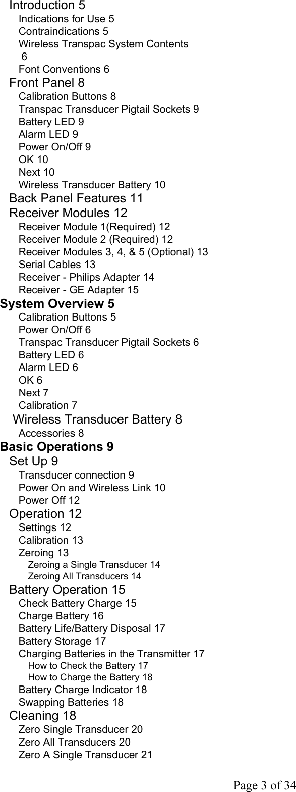
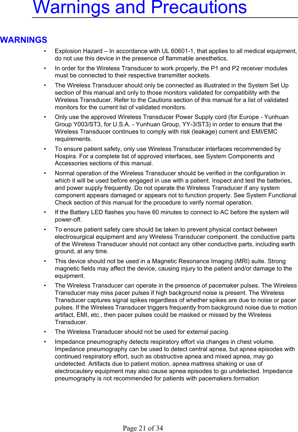
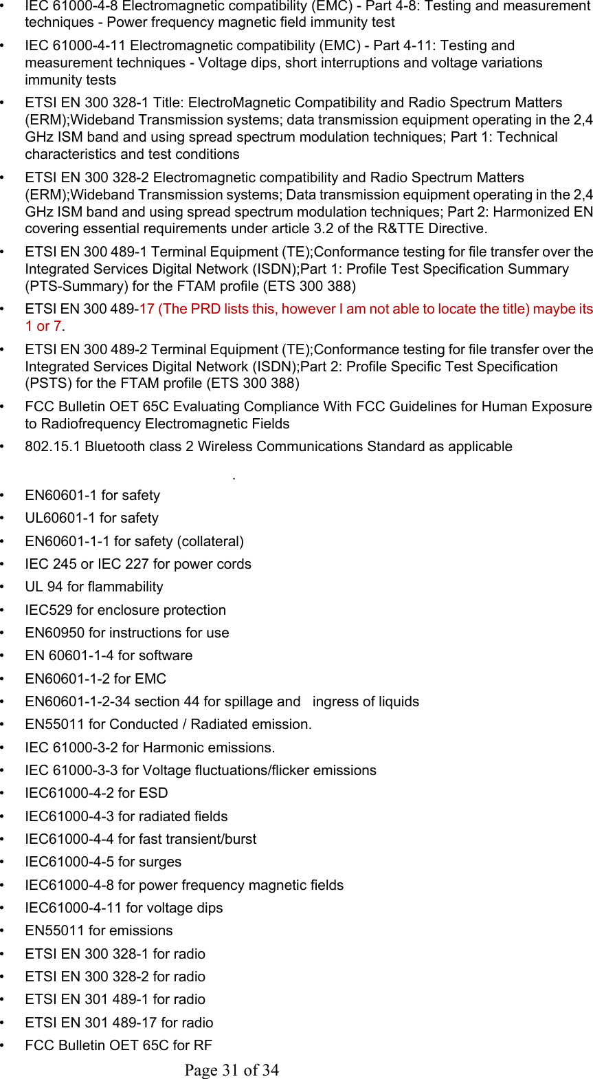
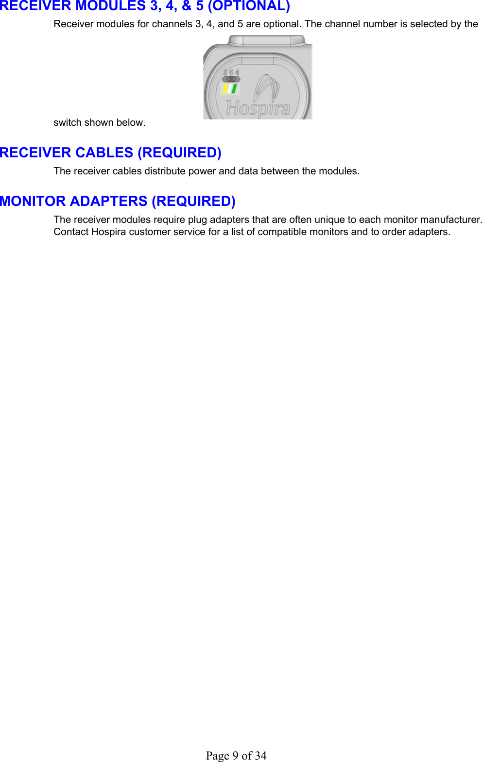
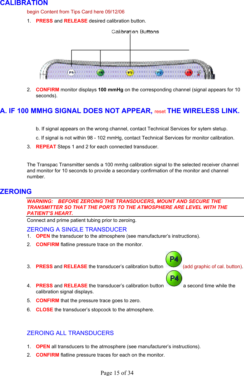
![• • • • • • • • Transmitter Front Panel The front panel features include the following user interface: Calibration Buttons Pressure Transducer Pigtail Sockets Battery LED Alarm LED Power On/Off Button OK Button Next Button Pressure Transducer Mounting Positions CALIBRATION BUTTONS The calibration buttons send a 100 mmHg pressure signal to the selected channel for 10 seconds. The calibration button zeroes the channel if it is pressed while the calibration signal is displayed. Tr anspac T r ansducer Pigtail SocketsCalibration Buttons (P1-P5)PowerOn/Of fAlarm LEDOK ButtonNext ButtonBattery LEDTr anspacMountingPositions Figure 1.1 PRESSURE TRANSDUCER PIGTAIL SOCKETS The pressure transducer pigtail sockets are color coded to aid in blood pressure channel traceability from the patient monitor to the patient. Inserting a pressure transducer plug into a socket triggers power-on. BATTERY LEDS The battery indicator has 3 LEDs to indicate battery charge (full, medium, low). See [insert cross reference to go to the Battery LED table in chapter on Troubleshooting] When not connected to AC, the system powers-off after 60 minutes if the battery discharges to a predefined safe low voltage. When the transmitter is connected to AC, the LEDs flash to indicate that the battery is charging.](https://usermanual.wiki/Elcam-Medical-ACAL/13EAUPAWRLSYST/User-Guide-757780-Page-6.png)
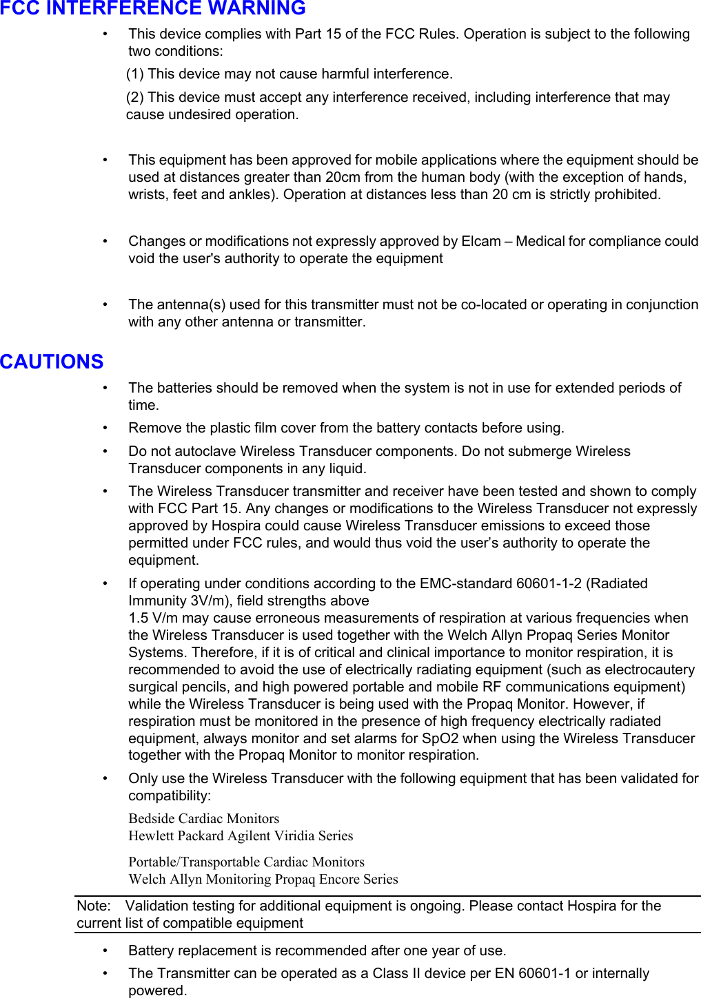
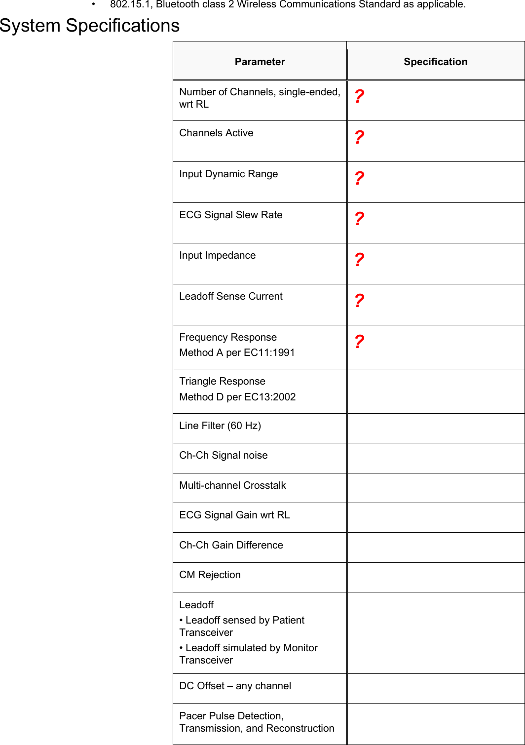
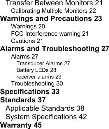
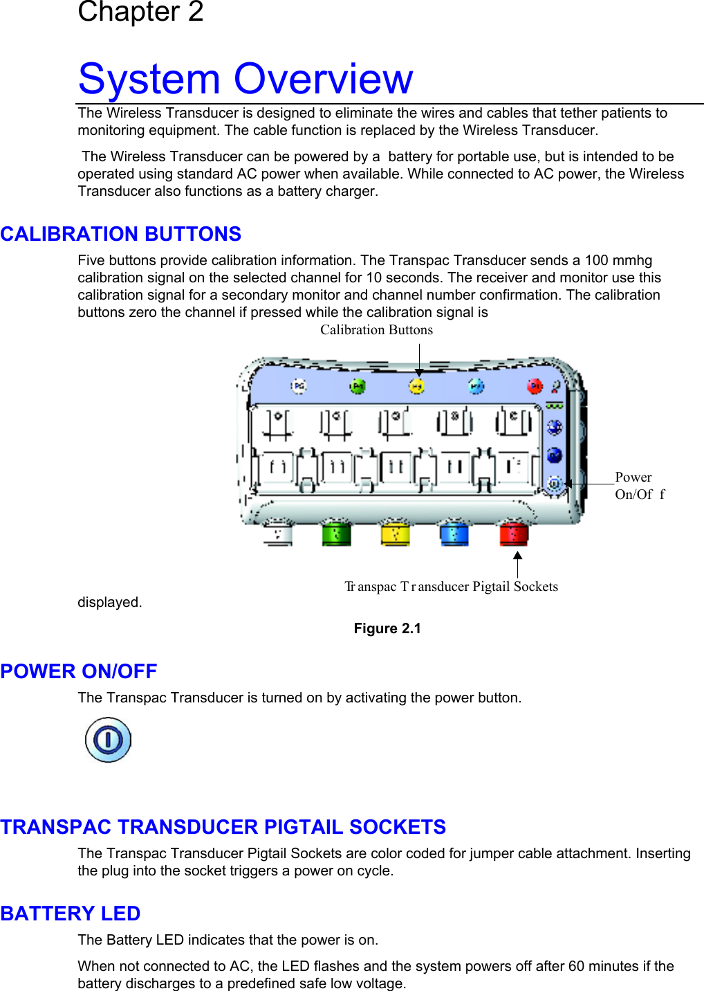
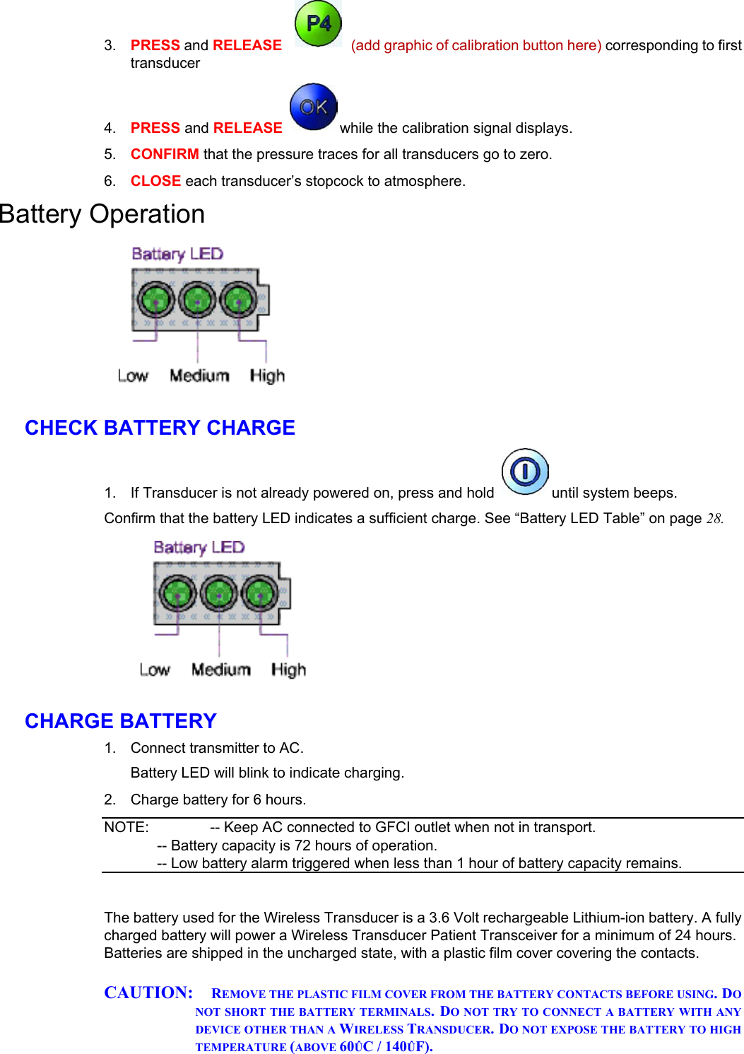
![Page 7 of 34 ALARM LED The Alarm LED flashes to indicate and alarm state. See [insert cross reference to go to the Alarm LED table in chapter on Troubleshooting] POWER ON/OFF The transmitter is switched ON or OFF by pressing the power button. OK The OK button is used during the wireless linking process.. A Wireless System for DPT equipped monitor will display a triangular “linking” waveform prior to the formation of a wireless link to a Wireless System for DPT transmitter. Press the OK button to immediately confirm the link. The OK button is also used during ZERO ALL. When a calibration signal is displayed, press the OK button to zero all channels. See Zeroing on page 13 for more information. NEXT The NEXT button cancels a wireless linking process if pressed while the “linking” signal is displayed on a monitor. The wireless linking process is then initiated with the next available monitor. If the NEXT button is pressed while the transmitter is already linked, the link is broken and a wireless linking process is initiated with the next available monitor. BATTERY The Li-ion battery is accessed via the back panel. A built-in battery charger automatically charges the battery whenever the transmitter is connected to AC power. Battery replacement should only be done by a trained technician. Contact Hospira customer support for replacement batteries. Back Panel](https://usermanual.wiki/Elcam-Medical-ACAL/13EAUPAWRLSYST/User-Guide-757780-Page-7.png)
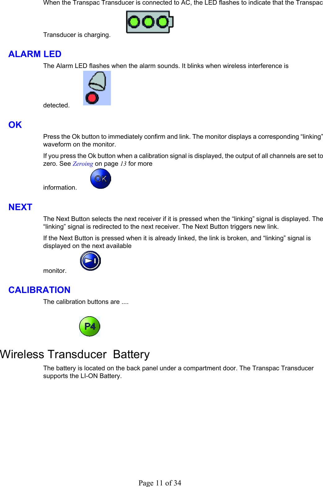

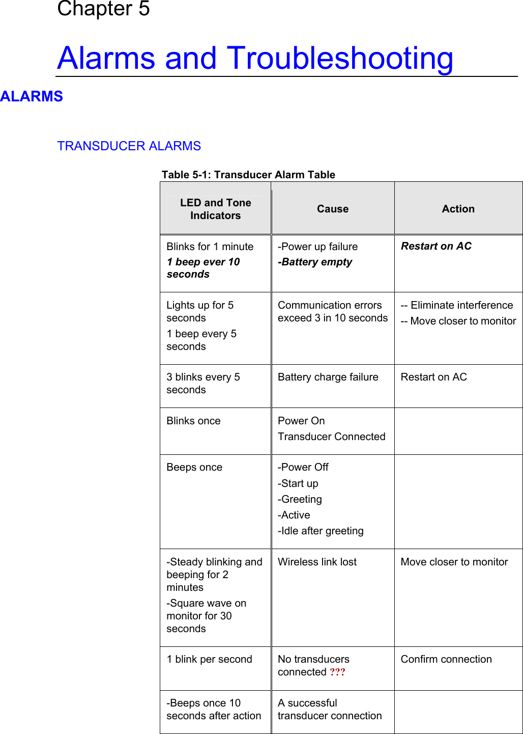
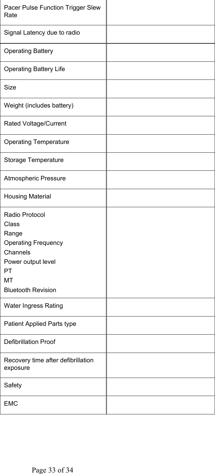
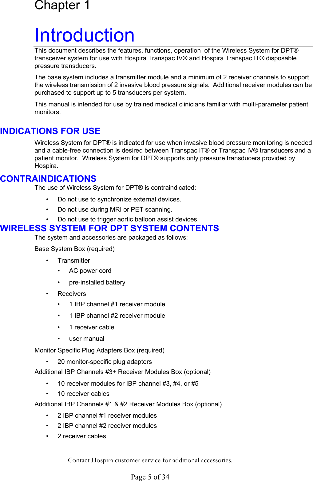
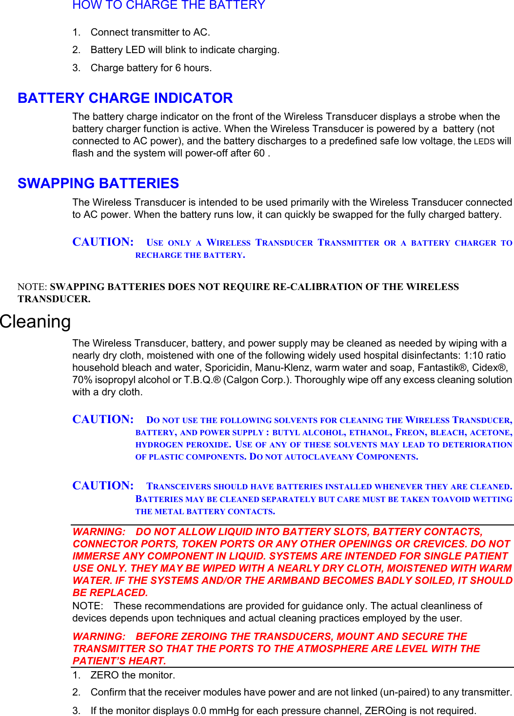
![Wireless Transpac System Operations Manual 430-11431-100 (09/06) Chapter 3 Basic Operations This chapter contains instructions and information about the basic operations of the transmitter/receiver device. Set Up Below are instructions on how to set up the transmitter, transducers, and receiver modules. TRANSDUCER CONNECTION WARNING: ONLY USE TRANSDUCERS PROVIDED BY HOSPIRA. USE OF OTHER TRANSDUCERS MAY DAMAGE THE TRANSMITTER AND VOIDS THE WARRANTY. NOTE: Transducer connection will trigger power on. 1. 2. SLIDE transducer into mounting rack. PLUG pigtail cable into socket under transducer. POWER ON AND WIRELESS LINK For normal operation, always keep transmitter connected to AC power. CONFIRM AC is connected (use GFCI outlet). 1. 2. If not already on, PRESS and HOLD power button [add graphic here] until system beeps. CONFIRM that the power status is OK 3. Figure 3.1Once the transmitter autotmatically links to the strongest receiver signal: a. CONFIRM triangle waveform is displayed on desired monitor. See below. b. PRESS “OK” Page 13 of 34](https://usermanual.wiki/Elcam-Medical-ACAL/13EAUPAWRLSYST/User-Guide-757780-Page-13.png)
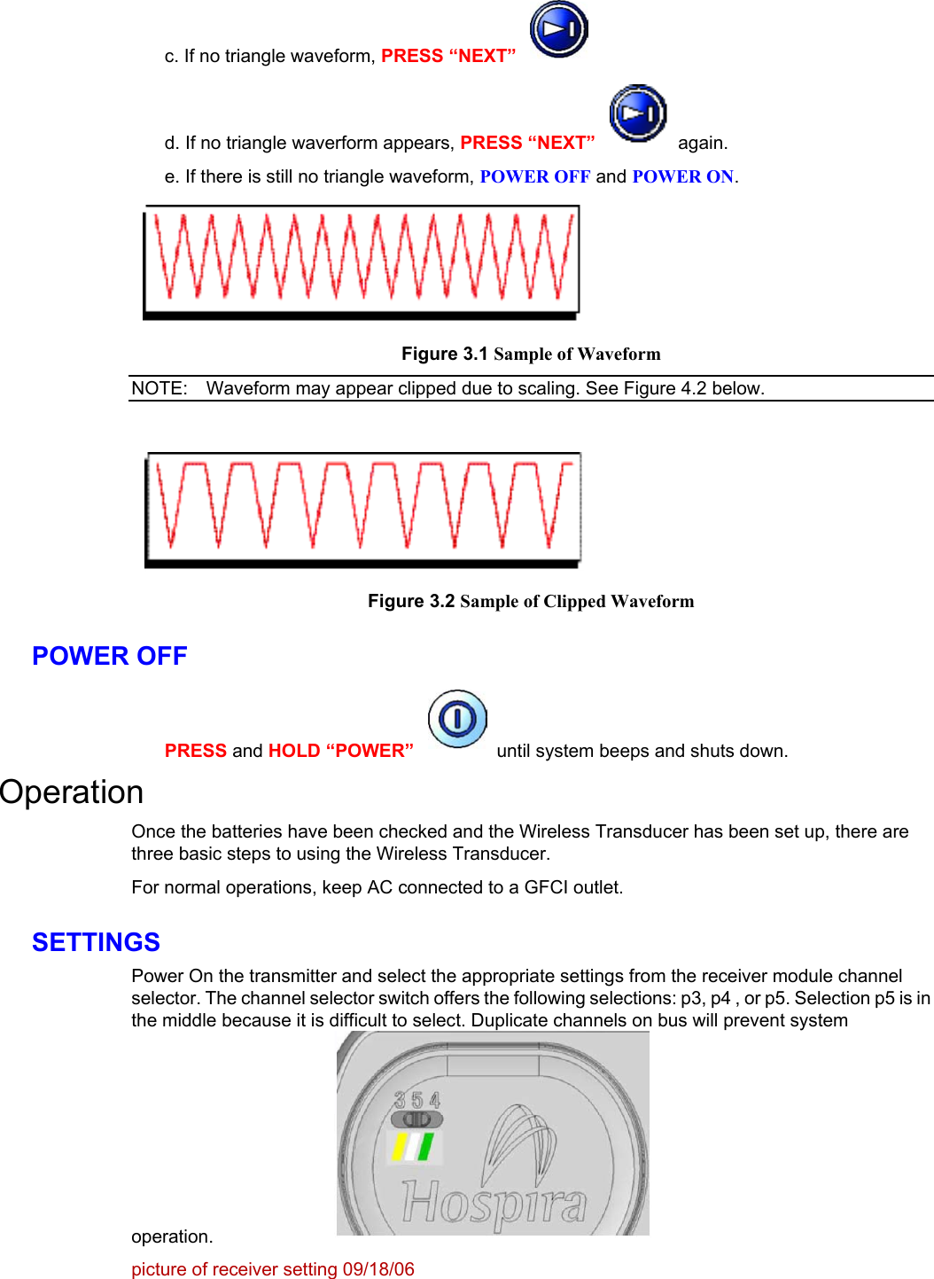

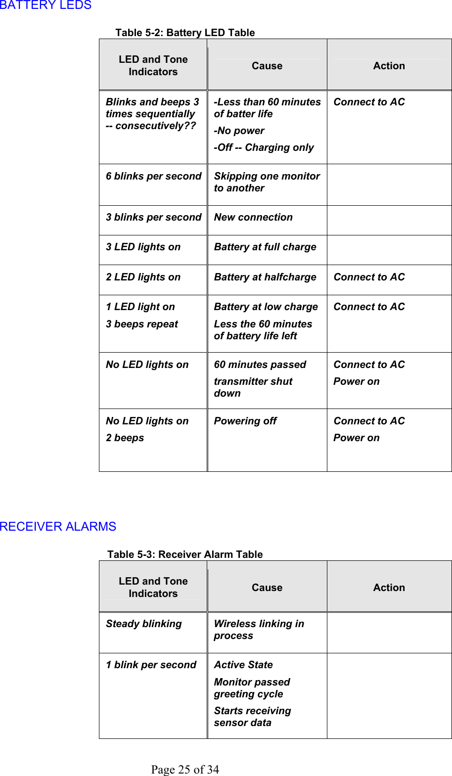
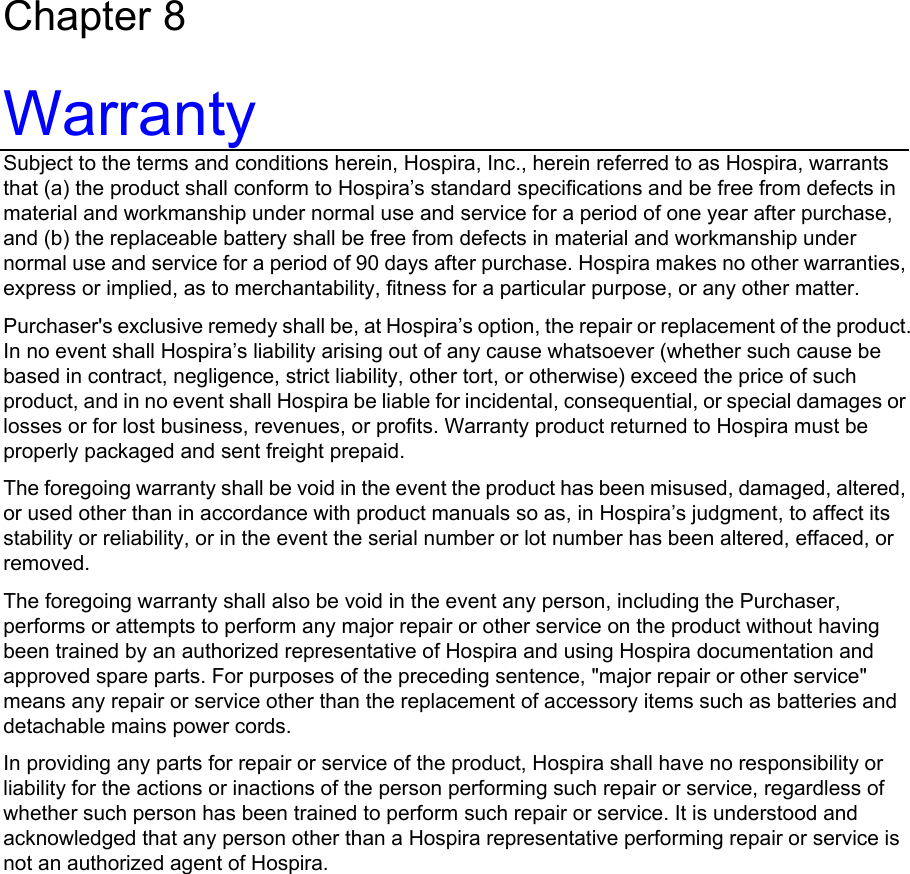
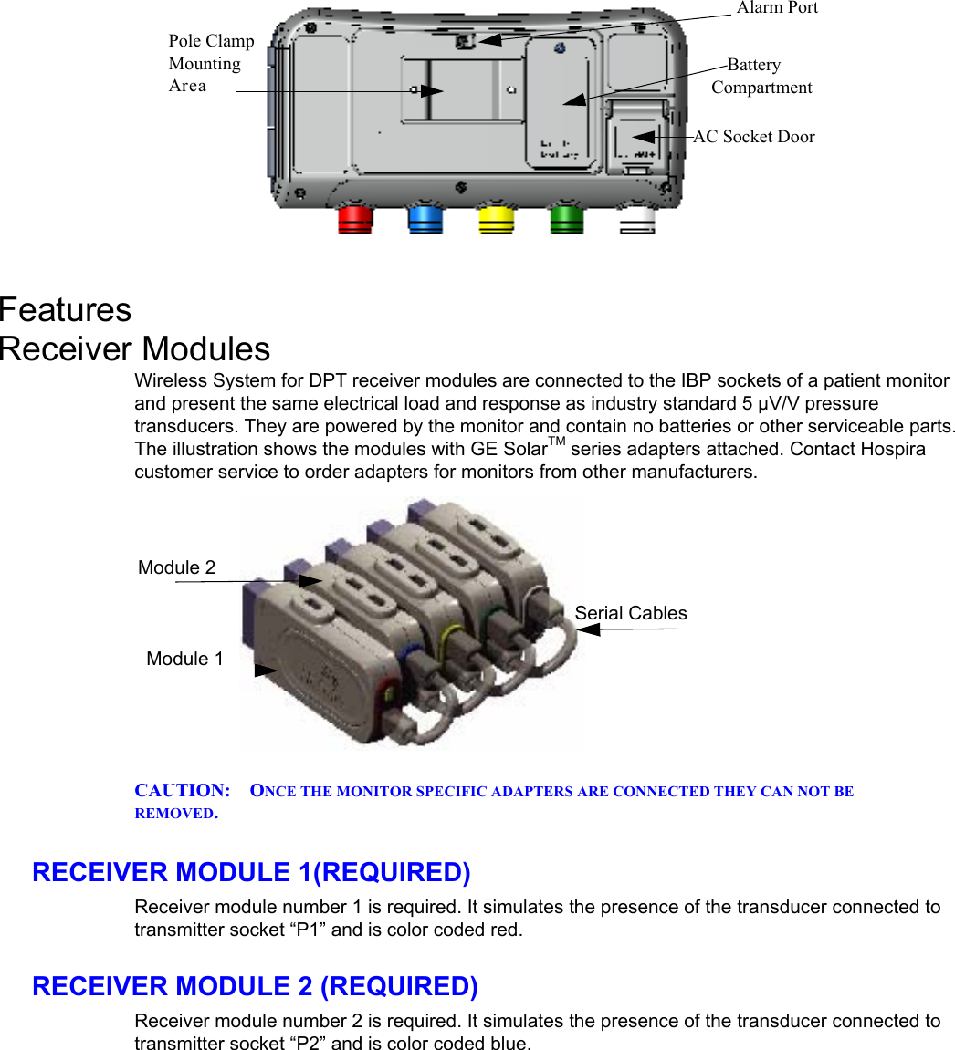
![Page 19 of 34 4. 5. 1. 2. 1. . 2. 3. 4. 5. 6. 7. 8. 1. 2. 3. 4. 5. 6. 7. 8. If the monitor does not display 0.0 mmHg for each pressure channel, ZERO each channel per the monitor manufacturer's instructions (GE example attached). If the monitor does not display 0.0 mmHg for each pressure channel after ZEROing, contact your technical services department. ZERO SINGLE TRANSDUCER Open transducer to atmosphere (see manufacturer’s instructions). Confirm flatline ZERO ALL TRANSDUCERS BEFORE LINKING TO A RECEIVER, CONFIRM THAT THE MONITOR IS ZEROED AS DESCRIBED ZEROING Confirm that the transmitter is linked to the desired receiver modules. Prepare all transducers for ZEROing per your established procedures (GE example attached). If the monitor displays 0.0 mmHg for all pressure channels, ZEROing is not required. To ZERO all channels, press OK. ["LAP" WILL BE USED FOR THE CURRENT PROTOTYPE] The pressure traces will go to 0.0 mmHg. NOTE: The ZERO request will be ignored if the any measured pressure is beyond +/- 150 mmHg or is not stable (within +/- 1 mmHg). Confirm that the monitor displays 0.0 mmHg for all pressure channels. If the monitor does not display 0.0 mmHg for all pressure channels, contact your technical services department. ZERO A SINGLE TRANSDUCER Before linking to a receiver, confirm that the monitor is ZEROed as described above. Confirm that the transmitter is linked to the desired receiver modules. Prepare the transducer for ZEROing per your established procedures (GE example attached). If the monitor displays 0.0 mmHg for the pressure channel, ZEROing is not required. To ZERO a single channel, press that channel's calibration button. While the 100 mmHg calibration signal is displayed on the monitor, press that calibration button again. The pressure trace will go to 0.0 mmHg. NOTE: The ZERO request will be ignored if the measured pressure is beyond +/- 150 mmHg or is not stable (within +/- 1 mmHg). Confirm that the monitor displays 0.0 mmHg. If the monitor does not display 0.0 mmHg for the ZEROed channel, contact your technical services department. GE Specs For Zero Balance Range +/- 150 Mmhg Accuracy +/- 1 mmHg Drift +/- 1 mmHg / 24 hrs 8.](https://usermanual.wiki/Elcam-Medical-ACAL/13EAUPAWRLSYST/User-Guide-757780-Page-19.png)
![1. 2. NOTE: 1. Transfer Between Monitors [10/04/06 aa. title means transferring from one monitor to another? suggested title: changing monitors or switching monitors] To redirect a wireless link from one patient monitor do the following: Press and release the Next Button. Follow the procedure for linking (power-on cycle) THIS PROCEDURES REQUIRES A SECOND PATIENT MONITOR CONFIGURED WITH HOSPIRA ERECEIVER MODULES. SEE SETTING UP RECEIVER MODULES CALIBRATING MULTIPLE MONITORS Calibrate one monitor at a time. This section goes in the setup portion. Wireless Transpac System Operations Manual 430-11431-100 (09/06)](https://usermanual.wiki/Elcam-Medical-ACAL/13EAUPAWRLSYST/User-Guide-757780-Page-20.png)